EP2620569B1 - Entsperrungssystem für eine fahrzeugtür - Google Patents
Entsperrungssystem für eine fahrzeugtür Download PDFInfo
- Publication number
- EP2620569B1 EP2620569B1 EP12199724.1A EP12199724A EP2620569B1 EP 2620569 B1 EP2620569 B1 EP 2620569B1 EP 12199724 A EP12199724 A EP 12199724A EP 2620569 B1 EP2620569 B1 EP 2620569B1
- Authority
- EP
- European Patent Office
- Prior art keywords
- latch
- door
- releasing
- latch device
- vehicle
- Prior art date
- Legal status (The legal status is an assumption and is not a legal conclusion. Google has not performed a legal analysis and makes no representation as to the accuracy of the status listed.)
- Not-in-force
Links
Images
Classifications
-
- E—FIXED CONSTRUCTIONS
- E05—LOCKS; KEYS; WINDOW OR DOOR FITTINGS; SAFES
- E05B—LOCKS; ACCESSORIES THEREFOR; HANDCUFFS
- E05B81/00—Power-actuated vehicle locks
- E05B81/54—Electrical circuits
- E05B81/90—Manual override in case of power failure
-
- E—FIXED CONSTRUCTIONS
- E05—LOCKS; KEYS; WINDOW OR DOOR FITTINGS; SAFES
- E05B—LOCKS; ACCESSORIES THEREFOR; HANDCUFFS
- E05B85/00—Details of vehicle locks not provided for in groups E05B77/00 - E05B83/00
- E05B85/10—Handles
-
- E—FIXED CONSTRUCTIONS
- E05—LOCKS; KEYS; WINDOW OR DOOR FITTINGS; SAFES
- E05B—LOCKS; ACCESSORIES THEREFOR; HANDCUFFS
- E05B77/00—Vehicle locks characterised by special functions or purposes
- E05B77/34—Protection against weather or dirt, e.g. against water ingress
-
- E—FIXED CONSTRUCTIONS
- E05—LOCKS; KEYS; WINDOW OR DOOR FITTINGS; SAFES
- E05B—LOCKS; ACCESSORIES THEREFOR; HANDCUFFS
- E05B81/00—Power-actuated vehicle locks
- E05B81/02—Power-actuated vehicle locks characterised by the type of actuators used
- E05B81/04—Electrical
- E05B81/06—Electrical using rotary motors
-
- E—FIXED CONSTRUCTIONS
- E05—LOCKS; KEYS; WINDOW OR DOOR FITTINGS; SAFES
- E05B—LOCKS; ACCESSORIES THEREFOR; HANDCUFFS
- E05B81/00—Power-actuated vehicle locks
- E05B81/54—Electrical circuits
- E05B81/64—Monitoring or sensing, e.g. by using switches or sensors
- E05B81/76—Detection of handle operation; Detection of a user approaching a handle; Electrical switching actions performed by door handles
- E05B81/78—Detection of handle operation; Detection of a user approaching a handle; Electrical switching actions performed by door handles as part of a hands-free locking or unlocking operation
Definitions
- the present invention relates to a latch releasing system for a vehicle door, comprising: an outer handle and a latch device having an electric actuator capable of exerting a power to release a latched state of the door having an outer surface, which in use is provided with the outer handle for opening and closing operations, the latch device being provided to the door in such a manner as to be capable of actuating the electric actuator in accordance with a predetermined operation by a vehicle user and latch releasing in accordance with a mechanical input of a latch-releasing operation force; and an emergency operation member having an operation section capable of being operated by the vehicle user from outside of a vehicle, the emergency operation member being provided to the door in such a manner as to be capable of exerting the latch-releasing operation force to the latch device.
- a latch releasing system for a vehicle door comprising an outer handle, a locking mechanism, an electric actuator, and an emergency operation member having an operation section capable of being operated by a vehicle user from outside of a vehicle, the emergency operation member being provided to the door in such a manner as to be capable of exerting a latch-releasing operation force to the locking mechanism, the operation section of the emergency operation member being provided at an outer surface of the door adjacent to the outer handle while having an outer surface continuously flush with an outer surface of the outer handle.
- the following latch releasing system for a vehicle door has been already known from Japanese Patent No. 4598668 , in which a latch is released by actuating an electric actuator of a latch device through a predetermined operation of a door switch or the like provided to a vehicle.
- the latch releasing system for a vehicle door includes an emergency operation member, which is provided in the door and can be operated from the outside of the vehicle.
- the emergency operation member is to mechanically input a latch-releasing operation force to the latch device in a case where electrical latch releasing of the latch device is impossible due to a dead battery or the like.
- Japanese Patent No. 4598668 discloses that the door is provided with an outer handle capable of being operated with a hand inserted into a recessed section provided on a vehicle body side, and that the emergency operation member is provided in such a manner as to be hidden from the outside by the outer handle.
- the emergency operation member When the emergency operation member is operated, a hand has to be deeply inserted into the outer handle for the operation. It is thus hard to say that the emergency operation member has a good operability.
- the emergency operation member is provided at the outer surface side of the door to increase the operability. Nevertheless, the structure in which the emergency operation member is simply provided at the outer surface side of the door may deteriorate the vehicle appearance.
- a cover member or the like is needed to prevent a mischief operation. Hence, the number of components is increased.
- An object of the present invention is to provide a latch releasing system for a vehicle door, which allows an emergency operation member to be provided at an outer surface side of a door to increase the operability, and which eliminates the need for a cover member covering the emergency operation member.
- a latch releasing system for a vehicle door comprising: an outer handle and a latch device having an electric actuator capable of exerting a power to release a latched state of the door having an outer surface, which in use is provided with the outer handle for opening and closing operations, the latch device being provided to the door in such a manner as to be capable of actuating the electric actuator in accordance with a predetermined operation by a vehicle user and latch releasing in accordance with a mechanical input of a latch-releasing operation force; and an emergency operation member having an operation section capable of being operated by the vehicle user from outside of a vehicle, the emergency operation member being provided to the door in such a manner as to be capable of exerting the latch-releasing operation force to the latch device, characterized in that the latch releasing system comprises a cylinder lock configured to be operated by a mechanical key to put the latch device in an unlocked state, so that in use after such unlocking of the latch device the emergency operation member can be manually operated by the vehicle user to exert the latch-releasing operation
- an electric motor 20 of an embodiment corresponds to the electric actuator of the present invention
- a front side door D of the embodiment corresponds to the door of the present invention.
- the operation section of the emergency operation member is provided at the outer surface side of the door, the operability of the emergency operation member can be increased.
- the operation section is disposed adjacent to the outer handle and has the outer surface continuously flush with the outer surface of the outer handle. Accordingly, it is possible to make such an appearance as if the outer handle and the operation section are integrated. This not only prevents a deterioration of the vehicle appearance, but also prevents an outsider from easily recognizing the operation section of the emergency operation member. Thus, there is no need for providing a cover member to prevent a mischief operation, and an increase in the number of components can be avoided.
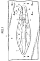
- an outer handle 7 made of a synthetic resin is attached to an outer surface of an outer panel 6 of a door, for example, a front side door D of the passenger vehicle.
- the outer handle 7 is for a vehicle user to grip in opening and closing the front side door D, and includes: a grip portion 7a extending long in a front-rear direction of the vehicle; a front supporting portion 7b continuously provided to a front end of the grip portion 7a; and a rear supporting portion 7c continuously provided to a rear end of the grip portion 7a.
- the rear supporting portion 7c includes: a thick portion 7ca forming a front half of the rear supporting portion 7c and having an outer surface continuously flush with an outer surface of the grip portion 7a; and a thin portion 7cb forming a rear half of the rear supporting portion 7c in such a manner as to have a height different from that of the thick portion 7ca.
- a sealing member 8 is interposed between the front supporting portion 7b of the outer handle 7 and the outer surface of the outer panel 6.
- a bolt 10 is screwed into a nut 9 molded and bonded to an inner surface of a front portion of the front supporting portion 7b, and is inserted through the outer panel 6 and the sealing member 8. By tightening the bolt 10, the front supporting portion 7b of the outer handle 7 is fixed to the outer panel 6.
- a base member 11 is fixed to a portion of the outer panel 6 corresponding to the rear supporting portion 7c of the outer handle 7.
- the base member 11 has: a plate-shaped base plate portion 11a abutting against the outer surface of the outer panel 6 from the outer side; and a bracket portion 11b provided integrally and continuously to the base plate portion 11a and penetrating an opening 12 provided in the outer panel 6 in such a manner as to extend inwardly into the outer panel 6.
- the base plate portion 11a is formed in such a manner as to project rearward of not only a portion disposed between the rear supporting portion 7c of the outer handle 7 and the outer panel 6 but also a rear end of the rear supporting portion 7c.
- the bracket portion 11b is integrally and continuously provided to the base plate portion 11a. Meanwhile, a nut 14 is molded and bonded to the thin portion 7cb of the rear supporting portion 7c. From the inside of the outer panel 6, a bolt 15 is inserted through the outer panel 6, the base plate portion 11a, and a sealing member 13 abutting against the entire outer surface of the base plate portion 11a. By screwing and tightening the bolt 15 into the nut 14, the rear supporting portion 7c of the outer handle 7 and the base member 11 are fixed to the outer panel 6 with the sealing member 13 sandwiched between the rear supporting portion 7c and the base plate portion 11a.
- a recessed insertion section 16 for inserting a hand to grip the grip portion 7a is formed. Further, a touch sensor 17 is additionally provided to the grip portion 7a to verify that the vehicle user has gripped the outer handle 7 to open the front side door D.
- a latch device 18 having an electric motor 20, which is an electric actuator, is provided to the front side door D.
- the latch device 18 is capable of switching a latched state where the front side door D in a closed state is engaged with and held to the vehicle body side and an unlatched state where an opening operation on the front side door D is possible.
- the latch device 18 is capable of switching an unlocked state enabling latch releasing of the front side door D and a locked state disabling the latch releasing of the front side door D.
- the latch device 18 is capable of actuating the electric motor 20 in the unlocked state and latch releasing in accordance with a mechanical input of a latch-releasing operation force.
- the electric motor 20 actuates to release the latched state of the latch device 18 through a predetermined operation of a legitimate vehicle user.
- the touch sensor 17 verifies that the vehicle user grips the outer handle 7 to open the front side door D
- an ID signal is wirelessly transferred between the vehicle and a portable device possessed by the vehicle user.
- the latch device 18 switches from the locked state to an unlocked state. Then, the electric motor 20 is actuated, and the latch device 18 releases the latched state.
- a cylinder body 22 of a cylinder lock 21 is fixed to a front portion of the base plate portion 11a of the base member 11.
- the cylinder lock 21 is configured to switch the latch device 18 from a locked state to an unlocked state.
- the cylinder body 22 of the cylinder lock 21 is housed in a housing hole 25 provided in the thick portion 7ca of the rear supporting portion 7c of the outer handle 7.
- a key hole 24 of the cylinder lock 21 is disposed at an outer-end opening of the housing hole 25.
- a rotor 23 of the cylinder lock 21 penetrates the outer panel 6, extends inwardly of the outer panel 6, and is connected to the latch device 18 with a connecting rod 26.
- the latch device 18 becomes an unlocked state by operating the cylinder lock 21 with a mechanical key.
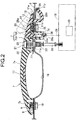
- an emergency operation member 28 capable of inputting a mechanical latch-releasing operation force to the latch device 18 is provided to the front side door D.
- the emergency operation member 28 integrally has: an operation section 28a provided adjacent to a rear portion of the outer handle 7 and at an outer surface side of the front side door D and capable of being operated from the outside of the front side door D; a supporting arm portion 28b extending from a rear portion of the operation section 28a to the inside of the front side door D and penetrating the sealing member 13, the base plate portion 11a of the base member 11, and the outer panel 6; and a connecting arm portion 28c extending from a front portion of the operation section 28a to the inside of the front side door D and penetrating the sealing member 13, the base plate portion 11a of the base member 11, and the outer panel 6.
- the operation section 28a is formed in such a manner as to cover the thin portion 7cb of the rear supporting portion 7c of the outer handle 7 from the outside, be provided adjacent to a rear portion of the thick portion 7ca, and project rearward from a rear end of the thin portion 7cb.
- the operation section 28a is provided at the outer surface side of the front side door D and has an outer surface continuously flush with the outer surface of the thick portion 7ca of the outer handle 7.
- the supporting arm portion 28b of the emergency operation member 28 is supported rotatably around a pin 29 by the bracket portion 11b of the base member 11.
- the emergency operation member 28 is rotatable between a position represented by a solid line in FIG. 2 and a position represented by a dashed line in FIG. 2 .
- recessed sections 30, 30 for facilitating the operation with a hand gripping the operation portion 28a may be formed in opposite side surfaces of the operation section 28a of the emergency operation member 28.
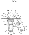
- a front portion of the thin portion 7cb of the rear supporting portion 7c of the outer handle 7 is integrally provided with a guide tubular portion 7d extending to the inside of the front side door D and penetrating the sealing member 13, the base plate portion 11a of the base member 11, and the outer panel 6.
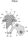
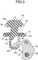
- the connecting arm portion 28c of the operation member 28 is inserted into the guide tubular portion 7d in such a manner as to move in the guide tubular portion 7d between a position shown in FIG. 4 and a position shown in FIG. 5 in accordance with a rotation of the operation member 28 around an axis of the pivot 29.
- An annular sealing member 31 surrounding the connecting arm portion 28c is mounted on the front portion of the thin portion 7cb of the rear supporting portion 7c of the outer handle 7.
- the sealing member 31 is elastically in contact with the operation section 28a when the connecting arm portion 28c is at the position shown in FIG. 4 .
- the guide tubular portion 7d is integrally and continuously provided with a lever supporting portion 7e.
- the lever supporting portion 7e supports a lever 33 rotatably around a pivot 32 extending in the front-rear direction of the vehicle and perpendicularly to a rotation axis of the emergency operation member 28, that is, a central axis of the pin 29.
- an opening 34 is provided, which opens the connecting arm portion 28c in an up-down direction.
- One end portion 33a of the lever 33 penetrates a slit 35 provided in the guide tubular portion 7d and is inserted into the opening 34.
- One side wall at the opening 34 on the tip end side of the connecting arm portion 28c forms an abutting surface 36.
- the one end portion 33a of the lever 33 abuts against the abutting surface 36.
- a torsion spring 37 is provided between the lever supporting portion 7e and the lever 33 to bias and rotate the lever 33 to a side where the one end portion 33a of the lever 33 is pushed against the abutting surface 36.
- the torsion spring 37 exerts a spring force to bias and rotate the operation section 28a of the operation member 28 toward a position shown in FIG. 4 .
- a joint member 38 is mounted on the other end portion of the lever 33. To the joint member 38, one end portion of a transmission rod 39 (see FIG. 2 ) is connected. The transmission rod 39 mechanically transmits a latch-releasing operation force to the latch device 18.
- the operation section 28a is disposed adjacent to the outer handle 7 and has the outer surface continuously flush with the outer surface of the outer handle 7. Accordingly, it is possible to make such an appearance as if the outer handle 7 and the operation section 28a are integrated. This not only prevents a deterioration of the vehicle appearance, but also prevents an outsider from easily recognizing the operation section 28a of the emergency operation member 28. Thus, there is no need for providing a cover member to prevent a mischief operation, and an increase in the number of components can be avoided.
Claims (1)
- Entsperrungssystem für eine Fahrzeugtür (D), umfassend:einen äußeren Griff (7) und eine Sperrvorrichtung (18), die einen elektrischen Aktuator (20) aufweist, der imstande ist, eine Kraft auszuüben, um einen Sperrzustand der Tür (D), die eine äußere Fläche aufweist, zu entsperren, die bei Verwendung mit dem äußeren Griff (7) für Öffnungs- und Schließbetätigungen bereitgestellt ist, wobei die Sperrvorrichtung (18) so an der Tür (D) bereitgestellt ist, dass sie imstande ist, den elektrischen Aktuator (20) in Übereinstimmung mit einer vorbestimmten Betätigung durch einen Fahrzeugnutzer und eine Entsperrung in Übereinstimmung mit einem mechanischen Eingang einer Entsperrungsbetätigungskraft auszulösen; undein Notbetätigungselement (28), das einen Betätigungsabschnitt (28a) aufweist, der imstande ist, durch den Fahrzeugnutzer von außerhalb eines Fahrzeugs betätigt zu werden, wobei das Notbetätigungselement (28) so an der Tür (D) bereitgestellt ist, dass es imstande ist, die Entsperrungsbetätigungskraft auf die Sperrvorrichtung (18) auszuüben,dadurch gekennzeichnet, dassdas Entsperrungssystem ein Zylinderschloss (21) umfasst, das konfiguriert ist, um durch einen mechanischen Schlüssel betätigt zu werden, um die Sperrvorrichtung (18) in einen entriegelten Zustand zu bringen, sodass bei Verwendung nach einem solchen Entriegeln der Sperrvorrichtung das Notbetätigungselement (28) manuell durch den Fahrzeugnutzer betätigt werden kann, um die Entsperrungsbetätigungskraft auf die Sperrvorrichtung (18) auszuüben, und dadurch, dassder Betätigungsabschnitt (28a) des Notbetätigungselements (28) an einer äußeren Flächenseite der Tür (D), die zum äußeren Griff (7) benachbart ist, bereitgestellt ist, während er eine äußere Fläche aufweist, die durchgehend mit einer äußeren Fläche des äußeren Griffs (7) bündig ist.
Applications Claiming Priority (1)
| Application Number | Priority Date | Filing Date | Title |
|---|---|---|---|
| JP2012012385A JP5543987B2 (ja) | 2012-01-24 | 2012-01-24 | 車両用ドアのラッチ解除装置 |
Publications (3)
| Publication Number | Publication Date |
|---|---|
| EP2620569A2 EP2620569A2 (de) | 2013-07-31 |
| EP2620569A3 EP2620569A3 (de) | 2016-10-12 |
| EP2620569B1 true EP2620569B1 (de) | 2019-02-20 |
Family
ID=47678532
Family Applications (1)
| Application Number | Title | Priority Date | Filing Date |
|---|---|---|---|
| EP12199724.1A Not-in-force EP2620569B1 (de) | 2012-01-24 | 2012-12-28 | Entsperrungssystem für eine fahrzeugtür |
Country Status (3)
| Country | Link |
|---|---|
| EP (1) | EP2620569B1 (de) |
| JP (1) | JP5543987B2 (de) |
| CN (1) | CN103216161B (de) |
Families Citing this family (10)
| Publication number | Priority date | Publication date | Assignee | Title |
|---|---|---|---|---|
| JP6180080B2 (ja) * | 2012-05-17 | 2017-08-16 | 株式会社アルファ | 車両のハンドル装置 |
| US20150059424A1 (en) * | 2013-09-04 | 2015-03-05 | Kiekert Aktiengesellschaft | Motor vehicle door |
| EP3141680B1 (de) * | 2015-09-09 | 2018-01-31 | U-Shin Italia S.p.A. | Elektronischer handgriff für eine fahrzeugtür |
| DE102017101415A1 (de) * | 2017-01-25 | 2018-07-26 | Daimler Ag | Türgriffanordnung für eine Fahrzeugtür |
| DE102017124568A1 (de) * | 2017-10-20 | 2019-04-25 | Dr. Ing. H.C. F. Porsche Aktiengesellschaft | Türaußengriffanordnung für ein Kraftfahrzeug |
| DE102017124518A1 (de) * | 2017-10-20 | 2019-04-25 | Kiekert Ag | Kraftfahrzeugtürschloss |
| DE102018107504A1 (de) * | 2018-03-28 | 2019-10-02 | Huf Hülsbeck & Fürst Gmbh & Co. Kg | Griffvorrichtung |
| KR102474382B1 (ko) * | 2018-06-25 | 2022-12-05 | 현대자동차 주식회사 | 차량용 도어 아웃사이드 핸들 |
| JP7194133B2 (ja) * | 2020-02-27 | 2022-12-21 | 株式会社ホンダロック | 車両のリッド開閉装置 |
| JP7375704B2 (ja) | 2020-08-05 | 2023-11-08 | トヨタ自動車株式会社 | 車両側部構造 |
Family Cites Families (9)
| Publication number | Priority date | Publication date | Assignee | Title |
|---|---|---|---|---|
| DE10121046A1 (de) * | 2001-04-28 | 2002-11-07 | Huf Huelsbeck & Fuerst Gmbh | Außenbetätigung für Fahrzeugschlösser von Türen, Klappen oder dgl. |
| JP4720395B2 (ja) * | 2005-09-20 | 2011-07-13 | アイシン精機株式会社 | 車両用ドアハンドル装置 |
| JP4598668B2 (ja) | 2005-12-19 | 2010-12-15 | 株式会社アルファ | 車両用ドアロック装置 |
| DE102008000190A1 (de) * | 2008-01-30 | 2009-08-06 | Huf Hülsbeck & Fürst Gmbh & Co. Kg | Türgriffanordnung mit verdecktem Schließzylinder |
| US8269615B2 (en) * | 2008-05-16 | 2012-09-18 | Aisin Seiki Kabushiki Kaisha | Door handle and locking system |
| JP2010024802A (ja) * | 2008-07-24 | 2010-02-04 | Aisin Seiki Co Ltd | 車両用ドアハンドル及び車両用ドアハンドル装置 |
| DE102008055993A1 (de) * | 2008-11-05 | 2010-05-06 | Kiekert Ag | Mechanisches Betätigungselement zum Betätigen eines Schließmechanismus einer Fahrzeugtür oder Fahrzeugklappe |
| JP2010216176A (ja) * | 2009-03-18 | 2010-09-30 | Aisin Seiki Co Ltd | 車両用ドアハンドル装置 |
| JP4909394B2 (ja) * | 2009-10-05 | 2012-04-04 | 三井金属アクト株式会社 | ドアラッチ装置 |
-
2012
- 2012-01-24 JP JP2012012385A patent/JP5543987B2/ja active Active
- 2012-12-28 EP EP12199724.1A patent/EP2620569B1/de not_active Not-in-force
-
2013
- 2013-01-23 CN CN201310023768.6A patent/CN103216161B/zh active Active
Non-Patent Citations (1)
| Title |
|---|
| None * |
Also Published As
| Publication number | Publication date |
|---|---|
| CN103216161A (zh) | 2013-07-24 |
| EP2620569A3 (de) | 2016-10-12 |
| CN103216161B (zh) | 2016-08-03 |
| JP5543987B2 (ja) | 2014-07-09 |
| EP2620569A2 (de) | 2013-07-31 |
| JP2013151799A (ja) | 2013-08-08 |
Similar Documents
| Publication | Publication Date | Title |
|---|---|---|
| EP2620569B1 (de) | Entsperrungssystem für eine fahrzeugtür | |
| CN107075887B (zh) | 表面平齐的舒适把手 | |
| US8904835B2 (en) | Door handle assembly for a vehicle | |
| EP3147436B1 (de) | Aussengriffvorrichtung für ein fahrzeug | |
| US8959964B2 (en) | Outer handle device for vehicle door | |
| US11174663B2 (en) | Exterior door handle arrangement for a motor vehicle | |
| CN109072642B (zh) | 用于打开机动车上的车门或舱盖的打开设备 | |
| US20090236863A1 (en) | Electric door latch apparatus | |
| CN109154169B (zh) | 用于车辆的活动部件的把手单元 | |
| US20090212577A1 (en) | Vehicle door lock device | |
| US9564701B2 (en) | Plug connector | |
| US20210332620A1 (en) | Door handle assembly for a vehicle door | |
| EP3303743A1 (de) | Türschlossbetätiger mit verschiedenen arten der türschlossoperation | |
| CN113272511B (zh) | 具有移出式门把手的车门 | |
| US20210363793A1 (en) | Door handle assembly for a vehicle door | |
| US20210363794A1 (en) | Door handle assembly for a vehicle door | |
| CN111356815A (zh) | 具有操作模块的机动车门把手装置 | |
| EP2615228B1 (de) | Entriegelungssystem für Fahrzeugtür | |
| EP2080857A3 (de) | Türaußengriffanordnung für Fahrzeuge | |
| JP2012087552A (ja) | ドアロック装置 | |
| CN114080484A (zh) | 机动车门锁 | |
| EP2312097B1 (de) | Verriegelungsvorrichtung mit doppelverriegelung für fahrzeugstüre | |
| CN112900994B (zh) | 用于机动车的门扇把手 | |
| CN112302437A (zh) | 用于车辆的电动门锁 | |
| JP3183438U (ja) | 自動車用窓ガラス割り装置 |
Legal Events
| Date | Code | Title | Description |
|---|---|---|---|
| PUAI | Public reference made under article 153(3) epc to a published international application that has entered the european phase |
Free format text: ORIGINAL CODE: 0009012 |
|
| 17P | Request for examination filed |
Effective date: 20121228 |
|
| AK | Designated contracting states |
Kind code of ref document: A2 Designated state(s): AL AT BE BG CH CY CZ DE DK EE ES FI FR GB GR HR HU IE IS IT LI LT LU LV MC MK MT NL NO PL PT RO RS SE SI SK SM TR |
|
| AX | Request for extension of the european patent |
Extension state: BA ME |
|
| PUAL | Search report despatched |
Free format text: ORIGINAL CODE: 0009013 |
|
| AK | Designated contracting states |
Kind code of ref document: A3 Designated state(s): AL AT BE BG CH CY CZ DE DK EE ES FI FR GB GR HR HU IE IS IT LI LT LU LV MC MK MT NL NO PL PT RO RS SE SI SK SM TR |
|
| AX | Request for extension of the european patent |
Extension state: BA ME |
|
| RIC1 | Information provided on ipc code assigned before grant |
Ipc: E05B 65/12 00000000ALI20160905BHEP Ipc: E05B 47/00 20060101ALI20160905BHEP Ipc: E05B 7/00 20060101AFI20160905BHEP |
|
| RBV | Designated contracting states (corrected) |
Designated state(s): AL AT BE BG CH CY CZ DE DK EE ES FI FR GB GR HR HU IE IS IT LI LT LU LV MC MK MT NL NO PL PT RO RS SE SI SK SM TR |
|
| REG | Reference to a national code |
Ref country code: DE Ref legal event code: R079 Ref document number: 602012056785 Country of ref document: DE Free format text: PREVIOUS MAIN CLASS: E05B0007000000 Ipc: E05B0081900000 |
|
| RIC1 | Information provided on ipc code assigned before grant |
Ipc: E05B 77/34 20140101ALN20180712BHEP Ipc: E05B 81/78 20140101ALN20180712BHEP Ipc: E05B 81/90 20140101AFI20180712BHEP Ipc: E05B 85/10 20140101ALI20180712BHEP Ipc: E05B 81/06 20140101ALN20180712BHEP |
|
| GRAP | Despatch of communication of intention to grant a patent |
Free format text: ORIGINAL CODE: EPIDOSNIGR1 |
|
| STAA | Information on the status of an ep patent application or granted ep patent |
Free format text: STATUS: GRANT OF PATENT IS INTENDED |
|
| INTG | Intention to grant announced |
Effective date: 20180822 |
|
| GRAS | Grant fee paid |
Free format text: ORIGINAL CODE: EPIDOSNIGR3 |
|
| GRAA | (expected) grant |
Free format text: ORIGINAL CODE: 0009210 |
|
| STAA | Information on the status of an ep patent application or granted ep patent |
Free format text: STATUS: THE PATENT HAS BEEN GRANTED |
|
| AK | Designated contracting states |
Kind code of ref document: B1 Designated state(s): AL AT BE BG CH CY CZ DE DK EE ES FI FR GB GR HR HU IE IS IT LI LT LU LV MC MK MT NL NO PL PT RO RS SE SI SK SM TR |
|
| REG | Reference to a national code |
Ref country code: GB Ref legal event code: FG4D |
|
| REG | Reference to a national code |
Ref country code: CH Ref legal event code: EP |
|
| REG | Reference to a national code |
Ref country code: DE Ref legal event code: R096 Ref document number: 602012056785 Country of ref document: DE |
|
| REG | Reference to a national code |
Ref country code: AT Ref legal event code: REF Ref document number: 1098388 Country of ref document: AT Kind code of ref document: T Effective date: 20190315 |
|
| REG | Reference to a national code |
Ref country code: IE Ref legal event code: FG4D |
|
| REG | Reference to a national code |
Ref country code: NL Ref legal event code: MP Effective date: 20190220 |
|
| REG | Reference to a national code |
Ref country code: LT Ref legal event code: MG4D |
|
| PG25 | Lapsed in a contracting state [announced via postgrant information from national office to epo] |
Ref country code: NL Free format text: LAPSE BECAUSE OF FAILURE TO SUBMIT A TRANSLATION OF THE DESCRIPTION OR TO PAY THE FEE WITHIN THE PRESCRIBED TIME-LIMIT Effective date: 20190220 Ref country code: FI Free format text: LAPSE BECAUSE OF FAILURE TO SUBMIT A TRANSLATION OF THE DESCRIPTION OR TO PAY THE FEE WITHIN THE PRESCRIBED TIME-LIMIT Effective date: 20190220 Ref country code: LT Free format text: LAPSE BECAUSE OF FAILURE TO SUBMIT A TRANSLATION OF THE DESCRIPTION OR TO PAY THE FEE WITHIN THE PRESCRIBED TIME-LIMIT Effective date: 20190220 Ref country code: NO Free format text: LAPSE BECAUSE OF FAILURE TO SUBMIT A TRANSLATION OF THE DESCRIPTION OR TO PAY THE FEE WITHIN THE PRESCRIBED TIME-LIMIT Effective date: 20190520 Ref country code: SE Free format text: LAPSE BECAUSE OF FAILURE TO SUBMIT A TRANSLATION OF THE DESCRIPTION OR TO PAY THE FEE WITHIN THE PRESCRIBED TIME-LIMIT Effective date: 20190220 Ref country code: PT Free format text: LAPSE BECAUSE OF FAILURE TO SUBMIT A TRANSLATION OF THE DESCRIPTION OR TO PAY THE FEE WITHIN THE PRESCRIBED TIME-LIMIT Effective date: 20190620 |
|
| PG25 | Lapsed in a contracting state [announced via postgrant information from national office to epo] |
Ref country code: BG Free format text: LAPSE BECAUSE OF FAILURE TO SUBMIT A TRANSLATION OF THE DESCRIPTION OR TO PAY THE FEE WITHIN THE PRESCRIBED TIME-LIMIT Effective date: 20190520 Ref country code: GR Free format text: LAPSE BECAUSE OF FAILURE TO SUBMIT A TRANSLATION OF THE DESCRIPTION OR TO PAY THE FEE WITHIN THE PRESCRIBED TIME-LIMIT Effective date: 20190521 Ref country code: HR Free format text: LAPSE BECAUSE OF FAILURE TO SUBMIT A TRANSLATION OF THE DESCRIPTION OR TO PAY THE FEE WITHIN THE PRESCRIBED TIME-LIMIT Effective date: 20190220 Ref country code: RS Free format text: LAPSE BECAUSE OF FAILURE TO SUBMIT A TRANSLATION OF THE DESCRIPTION OR TO PAY THE FEE WITHIN THE PRESCRIBED TIME-LIMIT Effective date: 20190220 Ref country code: LV Free format text: LAPSE BECAUSE OF FAILURE TO SUBMIT A TRANSLATION OF THE DESCRIPTION OR TO PAY THE FEE WITHIN THE PRESCRIBED TIME-LIMIT Effective date: 20190220 Ref country code: IS Free format text: LAPSE BECAUSE OF FAILURE TO SUBMIT A TRANSLATION OF THE DESCRIPTION OR TO PAY THE FEE WITHIN THE PRESCRIBED TIME-LIMIT Effective date: 20190620 |
|
| REG | Reference to a national code |
Ref country code: AT Ref legal event code: MK05 Ref document number: 1098388 Country of ref document: AT Kind code of ref document: T Effective date: 20190220 |
|
| PG25 | Lapsed in a contracting state [announced via postgrant information from national office to epo] |
Ref country code: RO Free format text: LAPSE BECAUSE OF FAILURE TO SUBMIT A TRANSLATION OF THE DESCRIPTION OR TO PAY THE FEE WITHIN THE PRESCRIBED TIME-LIMIT Effective date: 20190220 Ref country code: IT Free format text: LAPSE BECAUSE OF FAILURE TO SUBMIT A TRANSLATION OF THE DESCRIPTION OR TO PAY THE FEE WITHIN THE PRESCRIBED TIME-LIMIT Effective date: 20190220 Ref country code: CZ Free format text: LAPSE BECAUSE OF FAILURE TO SUBMIT A TRANSLATION OF THE DESCRIPTION OR TO PAY THE FEE WITHIN THE PRESCRIBED TIME-LIMIT Effective date: 20190220 Ref country code: SK Free format text: LAPSE BECAUSE OF FAILURE TO SUBMIT A TRANSLATION OF THE DESCRIPTION OR TO PAY THE FEE WITHIN THE PRESCRIBED TIME-LIMIT Effective date: 20190220 Ref country code: ES Free format text: LAPSE BECAUSE OF FAILURE TO SUBMIT A TRANSLATION OF THE DESCRIPTION OR TO PAY THE FEE WITHIN THE PRESCRIBED TIME-LIMIT Effective date: 20190220 Ref country code: AL Free format text: LAPSE BECAUSE OF FAILURE TO SUBMIT A TRANSLATION OF THE DESCRIPTION OR TO PAY THE FEE WITHIN THE PRESCRIBED TIME-LIMIT Effective date: 20190220 Ref country code: EE Free format text: LAPSE BECAUSE OF FAILURE TO SUBMIT A TRANSLATION OF THE DESCRIPTION OR TO PAY THE FEE WITHIN THE PRESCRIBED TIME-LIMIT Effective date: 20190220 Ref country code: DK Free format text: LAPSE BECAUSE OF FAILURE TO SUBMIT A TRANSLATION OF THE DESCRIPTION OR TO PAY THE FEE WITHIN THE PRESCRIBED TIME-LIMIT Effective date: 20190220 |
|
| REG | Reference to a national code |
Ref country code: DE Ref legal event code: R097 Ref document number: 602012056785 Country of ref document: DE |
|
| PG25 | Lapsed in a contracting state [announced via postgrant information from national office to epo] |
Ref country code: SM Free format text: LAPSE BECAUSE OF FAILURE TO SUBMIT A TRANSLATION OF THE DESCRIPTION OR TO PAY THE FEE WITHIN THE PRESCRIBED TIME-LIMIT Effective date: 20190220 Ref country code: PL Free format text: LAPSE BECAUSE OF FAILURE TO SUBMIT A TRANSLATION OF THE DESCRIPTION OR TO PAY THE FEE WITHIN THE PRESCRIBED TIME-LIMIT Effective date: 20190220 |
|
| PLBE | No opposition filed within time limit |
Free format text: ORIGINAL CODE: 0009261 |
|
| STAA | Information on the status of an ep patent application or granted ep patent |
Free format text: STATUS: NO OPPOSITION FILED WITHIN TIME LIMIT |
|
| PG25 | Lapsed in a contracting state [announced via postgrant information from national office to epo] |
Ref country code: AT Free format text: LAPSE BECAUSE OF FAILURE TO SUBMIT A TRANSLATION OF THE DESCRIPTION OR TO PAY THE FEE WITHIN THE PRESCRIBED TIME-LIMIT Effective date: 20190220 |
|
| 26N | No opposition filed |
Effective date: 20191121 |
|
| PG25 | Lapsed in a contracting state [announced via postgrant information from national office to epo] |
Ref country code: SI Free format text: LAPSE BECAUSE OF FAILURE TO SUBMIT A TRANSLATION OF THE DESCRIPTION OR TO PAY THE FEE WITHIN THE PRESCRIBED TIME-LIMIT Effective date: 20190220 |
|
| PG25 | Lapsed in a contracting state [announced via postgrant information from national office to epo] |
Ref country code: TR Free format text: LAPSE BECAUSE OF FAILURE TO SUBMIT A TRANSLATION OF THE DESCRIPTION OR TO PAY THE FEE WITHIN THE PRESCRIBED TIME-LIMIT Effective date: 20190220 |
|
| REG | Reference to a national code |
Ref country code: CH Ref legal event code: PL |
|
| REG | Reference to a national code |
Ref country code: BE Ref legal event code: MM Effective date: 20191231 |
|
| PG25 | Lapsed in a contracting state [announced via postgrant information from national office to epo] |
Ref country code: MC Free format text: LAPSE BECAUSE OF FAILURE TO SUBMIT A TRANSLATION OF THE DESCRIPTION OR TO PAY THE FEE WITHIN THE PRESCRIBED TIME-LIMIT Effective date: 20190220 |
|
| GBPC | Gb: european patent ceased through non-payment of renewal fee |
Effective date: 20191228 |
|
| PG25 | Lapsed in a contracting state [announced via postgrant information from national office to epo] |
Ref country code: IE Free format text: LAPSE BECAUSE OF NON-PAYMENT OF DUE FEES Effective date: 20191228 Ref country code: GB Free format text: LAPSE BECAUSE OF NON-PAYMENT OF DUE FEES Effective date: 20191228 Ref country code: FR Free format text: LAPSE BECAUSE OF NON-PAYMENT OF DUE FEES Effective date: 20191231 Ref country code: LU Free format text: LAPSE BECAUSE OF NON-PAYMENT OF DUE FEES Effective date: 20191228 |
|
| PG25 | Lapsed in a contracting state [announced via postgrant information from national office to epo] |
Ref country code: CH Free format text: LAPSE BECAUSE OF NON-PAYMENT OF DUE FEES Effective date: 20191231 Ref country code: LI Free format text: LAPSE BECAUSE OF NON-PAYMENT OF DUE FEES Effective date: 20191231 Ref country code: BE Free format text: LAPSE BECAUSE OF NON-PAYMENT OF DUE FEES Effective date: 20191231 |
|
| PG25 | Lapsed in a contracting state [announced via postgrant information from national office to epo] |
Ref country code: CY Free format text: LAPSE BECAUSE OF FAILURE TO SUBMIT A TRANSLATION OF THE DESCRIPTION OR TO PAY THE FEE WITHIN THE PRESCRIBED TIME-LIMIT Effective date: 20190220 |
|
| PG25 | Lapsed in a contracting state [announced via postgrant information from national office to epo] |
Ref country code: MT Free format text: LAPSE BECAUSE OF FAILURE TO SUBMIT A TRANSLATION OF THE DESCRIPTION OR TO PAY THE FEE WITHIN THE PRESCRIBED TIME-LIMIT Effective date: 20190220 Ref country code: HU Free format text: LAPSE BECAUSE OF FAILURE TO SUBMIT A TRANSLATION OF THE DESCRIPTION OR TO PAY THE FEE WITHIN THE PRESCRIBED TIME-LIMIT; INVALID AB INITIO Effective date: 20121228 |
|
| PGFP | Annual fee paid to national office [announced via postgrant information from national office to epo] |
Ref country code: DE Payment date: 20211102 Year of fee payment: 10 |
|
| PG25 | Lapsed in a contracting state [announced via postgrant information from national office to epo] |
Ref country code: MK Free format text: LAPSE BECAUSE OF FAILURE TO SUBMIT A TRANSLATION OF THE DESCRIPTION OR TO PAY THE FEE WITHIN THE PRESCRIBED TIME-LIMIT Effective date: 20190220 |
|
| REG | Reference to a national code |
Ref country code: DE Ref legal event code: R119 Ref document number: 602012056785 Country of ref document: DE |
|
| PG25 | Lapsed in a contracting state [announced via postgrant information from national office to epo] |
Ref country code: DE Free format text: LAPSE BECAUSE OF NON-PAYMENT OF DUE FEES Effective date: 20230701 |