EP2620569B1 - Latch releasing system for vehicle door - Google Patents
Latch releasing system for vehicle door Download PDFInfo
- Publication number
- EP2620569B1 EP2620569B1 EP12199724.1A EP12199724A EP2620569B1 EP 2620569 B1 EP2620569 B1 EP 2620569B1 EP 12199724 A EP12199724 A EP 12199724A EP 2620569 B1 EP2620569 B1 EP 2620569B1
- Authority
- EP
- European Patent Office
- Prior art keywords
- latch
- door
- releasing
- latch device
- vehicle
- Prior art date
- Legal status (The legal status is an assumption and is not a legal conclusion. Google has not performed a legal analysis and makes no representation as to the accuracy of the status listed.)
- Not-in-force
Links
Images
Classifications
-
- E—FIXED CONSTRUCTIONS
- E05—LOCKS; KEYS; WINDOW OR DOOR FITTINGS; SAFES
- E05B—LOCKS; ACCESSORIES THEREFOR; HANDCUFFS
- E05B81/00—Power-actuated vehicle locks
- E05B81/54—Electrical circuits
- E05B81/90—Manual override in case of power failure
-
- E—FIXED CONSTRUCTIONS
- E05—LOCKS; KEYS; WINDOW OR DOOR FITTINGS; SAFES
- E05B—LOCKS; ACCESSORIES THEREFOR; HANDCUFFS
- E05B85/00—Details of vehicle locks not provided for in groups E05B77/00 - E05B83/00
- E05B85/10—Handles
-
- E—FIXED CONSTRUCTIONS
- E05—LOCKS; KEYS; WINDOW OR DOOR FITTINGS; SAFES
- E05B—LOCKS; ACCESSORIES THEREFOR; HANDCUFFS
- E05B77/00—Vehicle locks characterised by special functions or purposes
- E05B77/34—Protection against weather or dirt, e.g. against water ingress
-
- E—FIXED CONSTRUCTIONS
- E05—LOCKS; KEYS; WINDOW OR DOOR FITTINGS; SAFES
- E05B—LOCKS; ACCESSORIES THEREFOR; HANDCUFFS
- E05B81/00—Power-actuated vehicle locks
- E05B81/02—Power-actuated vehicle locks characterised by the type of actuators used
- E05B81/04—Electrical
- E05B81/06—Electrical using rotary motors
-
- E—FIXED CONSTRUCTIONS
- E05—LOCKS; KEYS; WINDOW OR DOOR FITTINGS; SAFES
- E05B—LOCKS; ACCESSORIES THEREFOR; HANDCUFFS
- E05B81/00—Power-actuated vehicle locks
- E05B81/54—Electrical circuits
- E05B81/64—Monitoring or sensing, e.g. by using switches or sensors
- E05B81/76—Detection of handle operation; Detection of a user approaching a handle; Electrical switching actions performed by door handles
- E05B81/78—Detection of handle operation; Detection of a user approaching a handle; Electrical switching actions performed by door handles as part of a hands-free locking or unlocking operation
Description
- The present invention relates to a latch releasing system for a vehicle door, comprising: an outer handle and a latch device having an electric actuator capable of exerting a power to release a latched state of the door having an outer surface, which in use is provided with the outer handle for opening and closing operations, the latch device being provided to the door in such a manner as to be capable of actuating the electric actuator in accordance with a predetermined operation by a vehicle user and latch releasing in accordance with a mechanical input of a latch-releasing operation force; and an emergency operation member having an operation section capable of being operated by the vehicle user from outside of a vehicle, the emergency operation member being provided to the door in such a manner as to be capable of exerting the latch-releasing operation force to the latch device.
- It is known from
DE 10 2008 055993 to provide a latch releasing system for a vehicle door, comprising an outer handle, a locking mechanism, an electric actuator, and an emergency operation member having an operation section capable of being operated by a vehicle user from outside of a vehicle, the emergency operation member being provided to the door in such a manner as to be capable of exerting a latch-releasing operation force to the locking mechanism, the operation section of the emergency operation member being provided at an outer surface of the door adjacent to the outer handle while having an outer surface continuously flush with an outer surface of the outer handle. - The following latch releasing system for a vehicle door has been already known from Japanese Patent No.
4598668 - Japanese Patent No.
4598668 - The present invention has been made in view of such a circumstance. An object of the present invention is to provide a latch releasing system for a vehicle door, which allows an emergency operation member to be provided at an outer surface side of a door to increase the operability, and which eliminates the need for a cover member covering the emergency operation member.
- According to the present invention, there is provided a latch releasing system for a vehicle door, comprising: an outer handle and a latch device having an electric actuator capable of exerting a power to release a latched state of the door having an outer surface, which in use is provided with the outer handle for opening and closing operations, the latch device being provided to the door in such a manner as to be capable of actuating the electric actuator in accordance with a predetermined operation by a vehicle user and latch releasing in accordance with a mechanical input of a latch-releasing operation force; and an emergency operation member having an operation section capable of being operated by the vehicle user from outside of a vehicle, the emergency operation member being provided to the door in such a manner as to be capable of exerting the latch-releasing operation force to the latch device, characterized in that the latch releasing system comprises a cylinder lock configured to be operated by a mechanical key to put the latch device in an unlocked state, so that in use after such unlocking of the latch device the emergency operation member can be manually operated by the vehicle user to exert the latch-releasing operation force to the latch device, and in that the operation section of the emergency operation member is provided at an outer surface side of the door adjacent to the outer handle while having an outer surface continuously flush with an outer surface of the outer handle.
- Here, an
electric motor 20 of an embodiment corresponds to the electric actuator of the present invention; and a front side door D of the embodiment corresponds to the door of the present invention. - According to the above configuration of the present invention, since the operation section of the emergency operation member is provided at the outer surface side of the door, the operability of the emergency operation member can be increased. Moreover, the operation section is disposed adjacent to the outer handle and has the outer surface continuously flush with the outer surface of the outer handle. Accordingly, it is possible to make such an appearance as if the outer handle and the operation section are integrated. This not only prevents a deterioration of the vehicle appearance, but also prevents an outsider from easily recognizing the operation section of the emergency operation member. Thus, there is no need for providing a cover member to prevent a mischief operation, and an increase in the number of components can be avoided.
-
- [
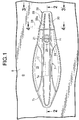
FIG. 1 ] It is a side view of an essential part of a passenger vehicle. - [
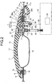
FIG. 2 ] It is a sectional view taken along a line 2-2 inFIG. 1 . - [
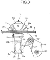
FIG. 3 ] It is a sectional view taken along a line 3-3 inFIG. 1 . - [
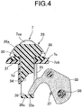
FIG. 4 ] It is a sectional view taken along a line 4-4 inFIG. 1 . - [
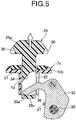
FIG. 5 ] It is a sectional view corresponding toFIG. 4 in a state where an emergency operation member is operated. - Hereinafter, an embodiment of the present invention will be described with reference to
FIGS. 1 to 5 attached hereto. At first, inFIGS. 1 and2 , anouter handle 7 made of a synthetic resin is attached to an outer surface of anouter panel 6 of a door, for example, a front side door D of the passenger vehicle. Theouter handle 7 is for a vehicle user to grip in opening and closing the front side door D, and includes: agrip portion 7a extending long in a front-rear direction of the vehicle; a front supportingportion 7b continuously provided to a front end of thegrip portion 7a; and a rear supportingportion 7c continuously provided to a rear end of thegrip portion 7a. Furthermore, the rear supportingportion 7c includes: a thick portion 7ca forming a front half of the rear supportingportion 7c and having an outer surface continuously flush with an outer surface of thegrip portion 7a; and a thin portion 7cb forming a rear half of the rear supportingportion 7c in such a manner as to have a height different from that of the thick portion 7ca. - A sealing member 8 is interposed between the
front supporting portion 7b of theouter handle 7 and the outer surface of theouter panel 6. Abolt 10 is screwed into anut 9 molded and bonded to an inner surface of a front portion of thefront supporting portion 7b, and is inserted through theouter panel 6 and the sealing member 8. By tightening thebolt 10, thefront supporting portion 7b of theouter handle 7 is fixed to theouter panel 6. - Moreover, a
base member 11 is fixed to a portion of theouter panel 6 corresponding to the rear supportingportion 7c of theouter handle 7. Thebase member 11 has: a plate-shapedbase plate portion 11a abutting against the outer surface of theouter panel 6 from the outer side; and abracket portion 11b provided integrally and continuously to thebase plate portion 11a and penetrating anopening 12 provided in theouter panel 6 in such a manner as to extend inwardly into theouter panel 6. Thebase plate portion 11a is formed in such a manner as to project rearward of not only a portion disposed between the rear supportingportion 7c of theouter handle 7 and theouter panel 6 but also a rear end of the rear supportingportion 7c. At the portion projecting rearward of the rear end of the rear supportingportion 7c, thebracket portion 11b is integrally and continuously provided to thebase plate portion 11a. Meanwhile, anut 14 is molded and bonded to the thin portion 7cb of the rear supportingportion 7c. From the inside of theouter panel 6, abolt 15 is inserted through theouter panel 6, thebase plate portion 11a, and a sealingmember 13 abutting against the entire outer surface of thebase plate portion 11a. By screwing and tightening thebolt 15 into thenut 14, the rear supportingportion 7c of theouter handle 7 and thebase member 11 are fixed to theouter panel 6 with the sealingmember 13 sandwiched between the rear supportingportion 7c and thebase plate portion 11a. - At a portion of the outer surface of the
outer panel 6 corresponding to thegrip portion 7a of theouter handle 7, arecessed insertion section 16 for inserting a hand to grip thegrip portion 7a is formed. Further, atouch sensor 17 is additionally provided to thegrip portion 7a to verify that the vehicle user has gripped theouter handle 7 to open the front side door D. - Furthermore, a
latch device 18 having anelectric motor 20, which is an electric actuator, is provided to the front side door D. Thelatch device 18 is capable of switching a latched state where the front side door D in a closed state is engaged with and held to the vehicle body side and an unlatched state where an opening operation on the front side door D is possible. Thelatch device 18 is capable of switching an unlocked state enabling latch releasing of the front side door D and a locked state disabling the latch releasing of the front side door D. Moreover, thelatch device 18 is capable of actuating theelectric motor 20 in the unlocked state and latch releasing in accordance with a mechanical input of a latch-releasing operation force. - While the closed front side door D is in a latched state, the
electric motor 20 actuates to release the latched state of thelatch device 18 through a predetermined operation of a legitimate vehicle user. In this embodiment, once thetouch sensor 17 verifies that the vehicle user grips theouter handle 7 to open the front side door D, an ID signal is wirelessly transferred between the vehicle and a portable device possessed by the vehicle user. When the legitimate vehicle user is verified with the ID signal, thelatch device 18 switches from the locked state to an unlocked state. Then, theelectric motor 20 is actuated, and thelatch device 18 releases the latched state. - Meanwhile, to prepare for a case where electrical latch releasing by the
latch device 18 is impossible due to a dead battery or the like, acylinder body 22 of acylinder lock 21 is fixed to a front portion of thebase plate portion 11a of thebase member 11. Thecylinder lock 21 is configured to switch thelatch device 18 from a locked state to an unlocked state. Thecylinder body 22 of thecylinder lock 21 is housed in ahousing hole 25 provided in the thick portion 7ca of the rear supportingportion 7c of theouter handle 7. Akey hole 24 of thecylinder lock 21 is disposed at an outer-end opening of thehousing hole 25. Moreover, arotor 23 of thecylinder lock 21 penetrates theouter panel 6, extends inwardly of theouter panel 6, and is connected to thelatch device 18 with aconnecting rod 26. - The
latch device 18 becomes an unlocked state by operating thecylinder lock 21 with a mechanical key. For a subsequent manual operation, anemergency operation member 28 capable of inputting a mechanical latch-releasing operation force to thelatch device 18 is provided to the front side door D. - The
emergency operation member 28 integrally has: anoperation section 28a provided adjacent to a rear portion of theouter handle 7 and at an outer surface side of the front side door D and capable of being operated from the outside of the front side door D; a supportingarm portion 28b extending from a rear portion of theoperation section 28a to the inside of the front side door D and penetrating the sealingmember 13, thebase plate portion 11a of thebase member 11, and theouter panel 6; and a connectingarm portion 28c extending from a front portion of theoperation section 28a to the inside of the front side door D and penetrating the sealingmember 13, thebase plate portion 11a of thebase member 11, and theouter panel 6. - The
operation section 28a is formed in such a manner as to cover the thin portion 7cb of the rear supportingportion 7c of theouter handle 7 from the outside, be provided adjacent to a rear portion of the thick portion 7ca, and project rearward from a rear end of the thin portion 7cb. Theoperation section 28a is provided at the outer surface side of the front side door D and has an outer surface continuously flush with the outer surface of the thick portion 7ca of theouter handle 7. - Referring to
FIG. 3 together, the supportingarm portion 28b of theemergency operation member 28 is supported rotatably around apin 29 by thebracket portion 11b of thebase member 11. Theemergency operation member 28 is rotatable between a position represented by a solid line inFIG. 2 and a position represented by a dashed line inFIG. 2 . Moreover, recessedsections operation portion 28a may be formed in opposite side surfaces of theoperation section 28a of theemergency operation member 28. - Referring to
FIG. 4 together, a front portion of the thin portion 7cb of the rear supportingportion 7c of theouter handle 7 is integrally provided with a guidetubular portion 7d extending to the inside of the front side door D and penetrating the sealingmember 13, thebase plate portion 11a of thebase member 11, and theouter panel 6. The connectingarm portion 28c of theoperation member 28 is inserted into the guidetubular portion 7d in such a manner as to move in the guidetubular portion 7d between a position shown inFIG. 4 and a position shown inFIG. 5 in accordance with a rotation of theoperation member 28 around an axis of thepivot 29. - An
annular sealing member 31 surrounding the connectingarm portion 28c is mounted on the front portion of the thin portion 7cb of the rear supportingportion 7c of theouter handle 7. The sealingmember 31 is elastically in contact with theoperation section 28a when the connectingarm portion 28c is at the position shown inFIG. 4 . - The guide
tubular portion 7d is integrally and continuously provided with alever supporting portion 7e. Thelever supporting portion 7e supports alever 33 rotatably around apivot 32 extending in the front-rear direction of the vehicle and perpendicularly to a rotation axis of theemergency operation member 28, that is, a central axis of thepin 29. - Meanwhile, on a tip end side of the connecting
arm portion 28c, anopening 34 is provided, which opens the connectingarm portion 28c in an up-down direction. Oneend portion 33a of thelever 33 penetrates aslit 35 provided in the guidetubular portion 7d and is inserted into theopening 34. One side wall at theopening 34 on the tip end side of the connectingarm portion 28c forms an abuttingsurface 36. The oneend portion 33a of thelever 33 abuts against the abuttingsurface 36. - In addition, a
torsion spring 37 is provided between thelever supporting portion 7e and thelever 33 to bias and rotate thelever 33 to a side where the oneend portion 33a of thelever 33 is pushed against the abuttingsurface 36. Thetorsion spring 37 exerts a spring force to bias and rotate theoperation section 28a of theoperation member 28 toward a position shown inFIG. 4 . - A
joint member 38 is mounted on the other end portion of thelever 33. To thejoint member 38, one end portion of a transmission rod 39 (seeFIG. 2 ) is connected. Thetransmission rod 39 mechanically transmits a latch-releasing operation force to thelatch device 18. - Next, operations of this embodiment will be described. Since the
operation section 28a of theemergency operation member 28 is provided at the outer surface side of the front side door D, the operability of theemergency operation member 28 can be increased. - Moreover, the
operation section 28a is disposed adjacent to theouter handle 7 and has the outer surface continuously flush with the outer surface of theouter handle 7. Accordingly, it is possible to make such an appearance as if theouter handle 7 and theoperation section 28a are integrated. This not only prevents a deterioration of the vehicle appearance, but also prevents an outsider from easily recognizing theoperation section 28a of theemergency operation member 28. Thus, there is no need for providing a cover member to prevent a mischief operation, and an increase in the number of components can be avoided. - An embodiment of the present invention is explained above, but the present invention is not limited to the above-mentioned embodiment and may be modified in a variety of ways as long as the modifications do not depart from the present invention described in claim.
-
- 7
- Outer handle
- 18
- Latch Device
- 20
- Electric motor, which is an electric actuator
- 28
- Emergency operation member
- 28a
- Operation section
- D
- Front side door, which is a door
Claims (1)
- A latch releasing system for a vehicle door (D), comprising:an outer handle (7) and a latch device (18) having an electric actuator (20) capable of exerting a power to release a latched state of the door (D) having an outer surface, which in use is provided with the outer handle (7) for opening and closing operations, the latch device (18) being provided to the door (D) in such a manner as to be capable of actuating the electric actuator (20) in accordance with a predetermined operation by a vehicle user and latch releasing in accordance with a mechanical input of a latch-releasing operation force; andan emergency operation member (28) having an operation section (28a) capable of being operated by the vehicle user from outside of a vehicle, the emergency operation member (28) being provided to the door (D) in such a manner as to be capable of exerting the latch-releasing operation force to the latch device (18),characterized in thatthe latch releasing system comprises a cylinder lock (21) configured to be operated by a mechanical key to put the latch device (18) in an unlocked state, so that in use after such unlocking of the latch device the emergency operation member (28) can be manually operated by the vehicle user to exert the latch-releasing operation force to the latch device (18), and in thatthe operation section (28a) of the emergency operation member (28) is provided at an outer surface side of the door (D) adjacent to the outer handle (7) while having an outer surface continuously flush with an outer surface of the outer handle (7).
Applications Claiming Priority (1)
| Application Number | Priority Date | Filing Date | Title |
|---|---|---|---|
| JP2012012385A JP5543987B2 (en) | 2012-01-24 | 2012-01-24 | Unlatch device for vehicle door |
Publications (3)
| Publication Number | Publication Date |
|---|---|
| EP2620569A2 EP2620569A2 (en) | 2013-07-31 |
| EP2620569A3 EP2620569A3 (en) | 2016-10-12 |
| EP2620569B1 true EP2620569B1 (en) | 2019-02-20 |
Family
ID=47678532
Family Applications (1)
| Application Number | Title | Priority Date | Filing Date |
|---|---|---|---|
| EP12199724.1A Not-in-force EP2620569B1 (en) | 2012-01-24 | 2012-12-28 | Latch releasing system for vehicle door |
Country Status (3)
| Country | Link |
|---|---|
| EP (1) | EP2620569B1 (en) |
| JP (1) | JP5543987B2 (en) |
| CN (1) | CN103216161B (en) |
Families Citing this family (9)
| Publication number | Priority date | Publication date | Assignee | Title |
|---|---|---|---|---|
| JP6180080B2 (en) * | 2012-05-17 | 2017-08-16 | 株式会社アルファ | Vehicle handle device |
| US20150059424A1 (en) * | 2013-09-04 | 2015-03-05 | Kiekert Aktiengesellschaft | Motor vehicle door |
| EP3141680B1 (en) | 2015-09-09 | 2018-01-31 | U-Shin Italia S.p.A. | Electronic handle for a vehicle door |
| DE102017101415A1 (en) * | 2017-01-25 | 2018-07-26 | Daimler Ag | Door handle assembly for a vehicle door |
| DE102017124518A1 (en) * | 2017-10-20 | 2019-04-25 | Kiekert Ag | Motor vehicle door lock |
| DE102018107504A1 (en) * | 2018-03-28 | 2019-10-02 | Huf Hülsbeck & Fürst Gmbh & Co. Kg | handle device |
| KR102474382B1 (en) * | 2018-06-25 | 2022-12-05 | 현대자동차 주식회사 | Door outside handle for vehicles |
| JP7194133B2 (en) * | 2020-02-27 | 2022-12-21 | 株式会社ホンダロック | vehicle lid opener |
| JP7375704B2 (en) | 2020-08-05 | 2023-11-08 | トヨタ自動車株式会社 | Vehicle side structure |
Family Cites Families (9)
| Publication number | Priority date | Publication date | Assignee | Title |
|---|---|---|---|---|
| DE10121046A1 (en) * | 2001-04-28 | 2002-11-07 | Huf Huelsbeck & Fuerst Gmbh | External actuation for vehicle locks on doors, flaps or the like. |
| JP4720395B2 (en) * | 2005-09-20 | 2011-07-13 | アイシン精機株式会社 | Vehicle door handle device |
| JP4598668B2 (en) | 2005-12-19 | 2010-12-15 | 株式会社アルファ | Vehicle door lock device |
| DE102008000190A1 (en) * | 2008-01-30 | 2009-08-06 | Huf Hülsbeck & Fürst Gmbh & Co. Kg | Door handle arrangement for motor vehicle, has handles which are formed in such manner that handles form cover for lock cylinder in resting position |
| US8269615B2 (en) * | 2008-05-16 | 2012-09-18 | Aisin Seiki Kabushiki Kaisha | Door handle and locking system |
| JP2010024802A (en) * | 2008-07-24 | 2010-02-04 | Aisin Seiki Co Ltd | Door handle for car and door handle device for car |
| DE102008055993A1 (en) * | 2008-11-05 | 2010-05-06 | Kiekert Ag | Mechanical actuating element for actuating locking mechanism of vehicle door or vehicle flap, is dimensioned, designed and arranged to produce force within range of releasing strength by intended operation |
| JP2010216176A (en) * | 2009-03-18 | 2010-09-30 | Aisin Seiki Co Ltd | Door handle device for vehicle |
| JP4909394B2 (en) * | 2009-10-05 | 2012-04-04 | 三井金属アクト株式会社 | Door latch device |
-
2012
- 2012-01-24 JP JP2012012385A patent/JP5543987B2/en active Active
- 2012-12-28 EP EP12199724.1A patent/EP2620569B1/en not_active Not-in-force
-
2013
- 2013-01-23 CN CN201310023768.6A patent/CN103216161B/en active Active
Non-Patent Citations (1)
| Title |
|---|
| None * |
Also Published As
| Publication number | Publication date |
|---|---|
| EP2620569A3 (en) | 2016-10-12 |
| CN103216161A (en) | 2013-07-24 |
| JP2013151799A (en) | 2013-08-08 |
| EP2620569A2 (en) | 2013-07-31 |
| JP5543987B2 (en) | 2014-07-09 |
| CN103216161B (en) | 2016-08-03 |
Similar Documents
| Publication | Publication Date | Title |
|---|---|---|
| EP2620569B1 (en) | Latch releasing system for vehicle door | |
| CN107075887B (en) | Comfortable handle with flush surface | |
| US8904835B2 (en) | Door handle assembly for a vehicle | |
| EP3147436B1 (en) | Outside handle device for vehicle | |
| US8959964B2 (en) | Outer handle device for vehicle door | |
| US11174663B2 (en) | Exterior door handle arrangement for a motor vehicle | |
| US20090236863A1 (en) | Electric door latch apparatus | |
| CN109072642B (en) | Opening device for opening a door or hatch on a motor vehicle | |
| CN109154169B (en) | Handle unit for a movable part of a vehicle | |
| US20090212577A1 (en) | Vehicle door lock device | |
| US9564701B2 (en) | Plug connector | |
| WO2016200743A1 (en) | Door lock operator having different types of door lock operation | |
| CN113272511B (en) | Vehicle door with a removal-type door handle | |
| US20210363793A1 (en) | Door handle assembly for a vehicle door | |
| US20210363794A1 (en) | Door handle assembly for a vehicle door | |
| EP2615228B1 (en) | Latch releasing system for vehicle door | |
| EP2080857A3 (en) | External door grip assembly for vehicles | |
| JP2012087552A (en) | Door lock device | |
| CN114080484A (en) | Motor vehicle door lock | |
| CN111356815A (en) | Motor vehicle door handle device with operating module | |
| EP2312097B1 (en) | Double-lock type vehicle door lock device | |
| CN112900994B (en) | Door leaf handle for a motor vehicle | |
| CN112302437A (en) | Electric door lock for vehicle | |
| JP3183438U (en) | Automotive window glass splitting device | |
| US20060152028A1 (en) | Vehicle door having a lockable compartment |
Legal Events
| Date | Code | Title | Description |
|---|---|---|---|
| PUAI | Public reference made under article 153(3) epc to a published international application that has entered the european phase |
Free format text: ORIGINAL CODE: 0009012 |
|
| 17P | Request for examination filed |
Effective date: 20121228 |
|
| AK | Designated contracting states |
Kind code of ref document: A2 Designated state(s): AL AT BE BG CH CY CZ DE DK EE ES FI FR GB GR HR HU IE IS IT LI LT LU LV MC MK MT NL NO PL PT RO RS SE SI SK SM TR |
|
| AX | Request for extension of the european patent |
Extension state: BA ME |
|
| PUAL | Search report despatched |
Free format text: ORIGINAL CODE: 0009013 |
|
| AK | Designated contracting states |
Kind code of ref document: A3 Designated state(s): AL AT BE BG CH CY CZ DE DK EE ES FI FR GB GR HR HU IE IS IT LI LT LU LV MC MK MT NL NO PL PT RO RS SE SI SK SM TR |
|
| AX | Request for extension of the european patent |
Extension state: BA ME |
|
| RIC1 | Information provided on ipc code assigned before grant |
Ipc: E05B 65/12 00000000ALI20160905BHEP Ipc: E05B 47/00 20060101ALI20160905BHEP Ipc: E05B 7/00 20060101AFI20160905BHEP |
|
| RBV | Designated contracting states (corrected) |
Designated state(s): AL AT BE BG CH CY CZ DE DK EE ES FI FR GB GR HR HU IE IS IT LI LT LU LV MC MK MT NL NO PL PT RO RS SE SI SK SM TR |
|
| REG | Reference to a national code |
Ref country code: DE Ref legal event code: R079 Ref document number: 602012056785 Country of ref document: DE Free format text: PREVIOUS MAIN CLASS: E05B0007000000 Ipc: E05B0081900000 |
|
| RIC1 | Information provided on ipc code assigned before grant |
Ipc: E05B 77/34 20140101ALN20180712BHEP Ipc: E05B 81/78 20140101ALN20180712BHEP Ipc: E05B 81/90 20140101AFI20180712BHEP Ipc: E05B 85/10 20140101ALI20180712BHEP Ipc: E05B 81/06 20140101ALN20180712BHEP |
|
| GRAP | Despatch of communication of intention to grant a patent |
Free format text: ORIGINAL CODE: EPIDOSNIGR1 |
|
| STAA | Information on the status of an ep patent application or granted ep patent |
Free format text: STATUS: GRANT OF PATENT IS INTENDED |
|
| INTG | Intention to grant announced |
Effective date: 20180822 |
|
| GRAS | Grant fee paid |
Free format text: ORIGINAL CODE: EPIDOSNIGR3 |
|
| GRAA | (expected) grant |
Free format text: ORIGINAL CODE: 0009210 |
|
| STAA | Information on the status of an ep patent application or granted ep patent |
Free format text: STATUS: THE PATENT HAS BEEN GRANTED |
|
| AK | Designated contracting states |
Kind code of ref document: B1 Designated state(s): AL AT BE BG CH CY CZ DE DK EE ES FI FR GB GR HR HU IE IS IT LI LT LU LV MC MK MT NL NO PL PT RO RS SE SI SK SM TR |
|
| REG | Reference to a national code |
Ref country code: GB Ref legal event code: FG4D |
|
| REG | Reference to a national code |
Ref country code: CH Ref legal event code: EP |
|
| REG | Reference to a national code |
Ref country code: DE Ref legal event code: R096 Ref document number: 602012056785 Country of ref document: DE |
|
| REG | Reference to a national code |
Ref country code: AT Ref legal event code: REF Ref document number: 1098388 Country of ref document: AT Kind code of ref document: T Effective date: 20190315 |
|
| REG | Reference to a national code |
Ref country code: IE Ref legal event code: FG4D |
|
| REG | Reference to a national code |
Ref country code: NL Ref legal event code: MP Effective date: 20190220 |
|
| REG | Reference to a national code |
Ref country code: LT Ref legal event code: MG4D |
|
| PG25 | Lapsed in a contracting state [announced via postgrant information from national office to epo] |
Ref country code: NL Free format text: LAPSE BECAUSE OF FAILURE TO SUBMIT A TRANSLATION OF THE DESCRIPTION OR TO PAY THE FEE WITHIN THE PRESCRIBED TIME-LIMIT Effective date: 20190220 Ref country code: FI Free format text: LAPSE BECAUSE OF FAILURE TO SUBMIT A TRANSLATION OF THE DESCRIPTION OR TO PAY THE FEE WITHIN THE PRESCRIBED TIME-LIMIT Effective date: 20190220 Ref country code: LT Free format text: LAPSE BECAUSE OF FAILURE TO SUBMIT A TRANSLATION OF THE DESCRIPTION OR TO PAY THE FEE WITHIN THE PRESCRIBED TIME-LIMIT Effective date: 20190220 Ref country code: NO Free format text: LAPSE BECAUSE OF FAILURE TO SUBMIT A TRANSLATION OF THE DESCRIPTION OR TO PAY THE FEE WITHIN THE PRESCRIBED TIME-LIMIT Effective date: 20190520 Ref country code: SE Free format text: LAPSE BECAUSE OF FAILURE TO SUBMIT A TRANSLATION OF THE DESCRIPTION OR TO PAY THE FEE WITHIN THE PRESCRIBED TIME-LIMIT Effective date: 20190220 Ref country code: PT Free format text: LAPSE BECAUSE OF FAILURE TO SUBMIT A TRANSLATION OF THE DESCRIPTION OR TO PAY THE FEE WITHIN THE PRESCRIBED TIME-LIMIT Effective date: 20190620 |
|
| PG25 | Lapsed in a contracting state [announced via postgrant information from national office to epo] |
Ref country code: BG Free format text: LAPSE BECAUSE OF FAILURE TO SUBMIT A TRANSLATION OF THE DESCRIPTION OR TO PAY THE FEE WITHIN THE PRESCRIBED TIME-LIMIT Effective date: 20190520 Ref country code: GR Free format text: LAPSE BECAUSE OF FAILURE TO SUBMIT A TRANSLATION OF THE DESCRIPTION OR TO PAY THE FEE WITHIN THE PRESCRIBED TIME-LIMIT Effective date: 20190521 Ref country code: HR Free format text: LAPSE BECAUSE OF FAILURE TO SUBMIT A TRANSLATION OF THE DESCRIPTION OR TO PAY THE FEE WITHIN THE PRESCRIBED TIME-LIMIT Effective date: 20190220 Ref country code: RS Free format text: LAPSE BECAUSE OF FAILURE TO SUBMIT A TRANSLATION OF THE DESCRIPTION OR TO PAY THE FEE WITHIN THE PRESCRIBED TIME-LIMIT Effective date: 20190220 Ref country code: LV Free format text: LAPSE BECAUSE OF FAILURE TO SUBMIT A TRANSLATION OF THE DESCRIPTION OR TO PAY THE FEE WITHIN THE PRESCRIBED TIME-LIMIT Effective date: 20190220 Ref country code: IS Free format text: LAPSE BECAUSE OF FAILURE TO SUBMIT A TRANSLATION OF THE DESCRIPTION OR TO PAY THE FEE WITHIN THE PRESCRIBED TIME-LIMIT Effective date: 20190620 |
|
| REG | Reference to a national code |
Ref country code: AT Ref legal event code: MK05 Ref document number: 1098388 Country of ref document: AT Kind code of ref document: T Effective date: 20190220 |
|
| PG25 | Lapsed in a contracting state [announced via postgrant information from national office to epo] |
Ref country code: RO Free format text: LAPSE BECAUSE OF FAILURE TO SUBMIT A TRANSLATION OF THE DESCRIPTION OR TO PAY THE FEE WITHIN THE PRESCRIBED TIME-LIMIT Effective date: 20190220 Ref country code: IT Free format text: LAPSE BECAUSE OF FAILURE TO SUBMIT A TRANSLATION OF THE DESCRIPTION OR TO PAY THE FEE WITHIN THE PRESCRIBED TIME-LIMIT Effective date: 20190220 Ref country code: CZ Free format text: LAPSE BECAUSE OF FAILURE TO SUBMIT A TRANSLATION OF THE DESCRIPTION OR TO PAY THE FEE WITHIN THE PRESCRIBED TIME-LIMIT Effective date: 20190220 Ref country code: SK Free format text: LAPSE BECAUSE OF FAILURE TO SUBMIT A TRANSLATION OF THE DESCRIPTION OR TO PAY THE FEE WITHIN THE PRESCRIBED TIME-LIMIT Effective date: 20190220 Ref country code: ES Free format text: LAPSE BECAUSE OF FAILURE TO SUBMIT A TRANSLATION OF THE DESCRIPTION OR TO PAY THE FEE WITHIN THE PRESCRIBED TIME-LIMIT Effective date: 20190220 Ref country code: AL Free format text: LAPSE BECAUSE OF FAILURE TO SUBMIT A TRANSLATION OF THE DESCRIPTION OR TO PAY THE FEE WITHIN THE PRESCRIBED TIME-LIMIT Effective date: 20190220 Ref country code: EE Free format text: LAPSE BECAUSE OF FAILURE TO SUBMIT A TRANSLATION OF THE DESCRIPTION OR TO PAY THE FEE WITHIN THE PRESCRIBED TIME-LIMIT Effective date: 20190220 Ref country code: DK Free format text: LAPSE BECAUSE OF FAILURE TO SUBMIT A TRANSLATION OF THE DESCRIPTION OR TO PAY THE FEE WITHIN THE PRESCRIBED TIME-LIMIT Effective date: 20190220 |
|
| REG | Reference to a national code |
Ref country code: DE Ref legal event code: R097 Ref document number: 602012056785 Country of ref document: DE |
|
| PG25 | Lapsed in a contracting state [announced via postgrant information from national office to epo] |
Ref country code: SM Free format text: LAPSE BECAUSE OF FAILURE TO SUBMIT A TRANSLATION OF THE DESCRIPTION OR TO PAY THE FEE WITHIN THE PRESCRIBED TIME-LIMIT Effective date: 20190220 Ref country code: PL Free format text: LAPSE BECAUSE OF FAILURE TO SUBMIT A TRANSLATION OF THE DESCRIPTION OR TO PAY THE FEE WITHIN THE PRESCRIBED TIME-LIMIT Effective date: 20190220 |
|
| PLBE | No opposition filed within time limit |
Free format text: ORIGINAL CODE: 0009261 |
|
| STAA | Information on the status of an ep patent application or granted ep patent |
Free format text: STATUS: NO OPPOSITION FILED WITHIN TIME LIMIT |
|
| PG25 | Lapsed in a contracting state [announced via postgrant information from national office to epo] |
Ref country code: AT Free format text: LAPSE BECAUSE OF FAILURE TO SUBMIT A TRANSLATION OF THE DESCRIPTION OR TO PAY THE FEE WITHIN THE PRESCRIBED TIME-LIMIT Effective date: 20190220 |
|
| 26N | No opposition filed |
Effective date: 20191121 |
|
| PG25 | Lapsed in a contracting state [announced via postgrant information from national office to epo] |
Ref country code: SI Free format text: LAPSE BECAUSE OF FAILURE TO SUBMIT A TRANSLATION OF THE DESCRIPTION OR TO PAY THE FEE WITHIN THE PRESCRIBED TIME-LIMIT Effective date: 20190220 |
|
| PG25 | Lapsed in a contracting state [announced via postgrant information from national office to epo] |
Ref country code: TR Free format text: LAPSE BECAUSE OF FAILURE TO SUBMIT A TRANSLATION OF THE DESCRIPTION OR TO PAY THE FEE WITHIN THE PRESCRIBED TIME-LIMIT Effective date: 20190220 |
|
| REG | Reference to a national code |
Ref country code: CH Ref legal event code: PL |
|
| REG | Reference to a national code |
Ref country code: BE Ref legal event code: MM Effective date: 20191231 |
|
| PG25 | Lapsed in a contracting state [announced via postgrant information from national office to epo] |
Ref country code: MC Free format text: LAPSE BECAUSE OF FAILURE TO SUBMIT A TRANSLATION OF THE DESCRIPTION OR TO PAY THE FEE WITHIN THE PRESCRIBED TIME-LIMIT Effective date: 20190220 |
|
| GBPC | Gb: european patent ceased through non-payment of renewal fee |
Effective date: 20191228 |
|
| PG25 | Lapsed in a contracting state [announced via postgrant information from national office to epo] |
Ref country code: IE Free format text: LAPSE BECAUSE OF NON-PAYMENT OF DUE FEES Effective date: 20191228 Ref country code: GB Free format text: LAPSE BECAUSE OF NON-PAYMENT OF DUE FEES Effective date: 20191228 Ref country code: FR Free format text: LAPSE BECAUSE OF NON-PAYMENT OF DUE FEES Effective date: 20191231 Ref country code: LU Free format text: LAPSE BECAUSE OF NON-PAYMENT OF DUE FEES Effective date: 20191228 |
|
| PG25 | Lapsed in a contracting state [announced via postgrant information from national office to epo] |
Ref country code: CH Free format text: LAPSE BECAUSE OF NON-PAYMENT OF DUE FEES Effective date: 20191231 Ref country code: LI Free format text: LAPSE BECAUSE OF NON-PAYMENT OF DUE FEES Effective date: 20191231 Ref country code: BE Free format text: LAPSE BECAUSE OF NON-PAYMENT OF DUE FEES Effective date: 20191231 |
|
| PG25 | Lapsed in a contracting state [announced via postgrant information from national office to epo] |
Ref country code: CY Free format text: LAPSE BECAUSE OF FAILURE TO SUBMIT A TRANSLATION OF THE DESCRIPTION OR TO PAY THE FEE WITHIN THE PRESCRIBED TIME-LIMIT Effective date: 20190220 |
|
| PG25 | Lapsed in a contracting state [announced via postgrant information from national office to epo] |
Ref country code: MT Free format text: LAPSE BECAUSE OF FAILURE TO SUBMIT A TRANSLATION OF THE DESCRIPTION OR TO PAY THE FEE WITHIN THE PRESCRIBED TIME-LIMIT Effective date: 20190220 Ref country code: HU Free format text: LAPSE BECAUSE OF FAILURE TO SUBMIT A TRANSLATION OF THE DESCRIPTION OR TO PAY THE FEE WITHIN THE PRESCRIBED TIME-LIMIT; INVALID AB INITIO Effective date: 20121228 |
|
| PGFP | Annual fee paid to national office [announced via postgrant information from national office to epo] |
Ref country code: DE Payment date: 20211102 Year of fee payment: 10 |
|
| PG25 | Lapsed in a contracting state [announced via postgrant information from national office to epo] |
Ref country code: MK Free format text: LAPSE BECAUSE OF FAILURE TO SUBMIT A TRANSLATION OF THE DESCRIPTION OR TO PAY THE FEE WITHIN THE PRESCRIBED TIME-LIMIT Effective date: 20190220 |
|
| REG | Reference to a national code |
Ref country code: DE Ref legal event code: R119 Ref document number: 602012056785 Country of ref document: DE |
|
| PG25 | Lapsed in a contracting state [announced via postgrant information from national office to epo] |
Ref country code: DE Free format text: LAPSE BECAUSE OF NON-PAYMENT OF DUE FEES Effective date: 20230701 |