EP2619543B1 - Modulares kapillarbrücken-viskosimeter - Google Patents
Modulares kapillarbrücken-viskosimeter Download PDFInfo
- Publication number
- EP2619543B1 EP2619543B1 EP11774083.7A EP11774083A EP2619543B1 EP 2619543 B1 EP2619543 B1 EP 2619543B1 EP 11774083 A EP11774083 A EP 11774083A EP 2619543 B1 EP2619543 B1 EP 2619543B1
- Authority
- EP
- European Patent Office
- Prior art keywords
- removable
- connection
- differential pressure
- pressure detection
- bulkhead
- Prior art date
- Legal status (The legal status is an assumption and is not a legal conclusion. Google has not performed a legal analysis and makes no representation as to the accuracy of the status listed.)
- Active
Links
- 238000001514 detection method Methods 0.000 claims description 21
- 239000012530 fluid Substances 0.000 claims description 7
- 238000004128 high performance liquid chromatography Methods 0.000 claims description 2
- 238000010586 diagram Methods 0.000 description 8
- 238000009434 installation Methods 0.000 description 4
- 239000002904 solvent Substances 0.000 description 4
- 238000013461 design Methods 0.000 description 3
- 238000002474 experimental method Methods 0.000 description 3
- 238000005259 measurement Methods 0.000 description 3
- 238000004458 analytical method Methods 0.000 description 2
- 238000005227 gel permeation chromatography Methods 0.000 description 2
- 239000000463 material Substances 0.000 description 2
- 238000000034 method Methods 0.000 description 2
- 238000010276 construction Methods 0.000 description 1
- 230000003247 decreasing effect Effects 0.000 description 1
- 230000000694 effects Effects 0.000 description 1
- 238000010828 elution Methods 0.000 description 1
- 238000002955 isolation Methods 0.000 description 1
- 238000004811 liquid chromatography Methods 0.000 description 1
- 238000004519 manufacturing process Methods 0.000 description 1
- 238000012986 modification Methods 0.000 description 1
- 230000004048 modification Effects 0.000 description 1
- 238000009428 plumbing Methods 0.000 description 1
- 238000000926 separation method Methods 0.000 description 1
- 229910001220 stainless steel Inorganic materials 0.000 description 1
- 239000010935 stainless steel Substances 0.000 description 1
Images
Classifications
-
- G—PHYSICS
- G01—MEASURING; TESTING
- G01N—INVESTIGATING OR ANALYSING MATERIALS BY DETERMINING THEIR CHEMICAL OR PHYSICAL PROPERTIES
- G01N11/00—Investigating flow properties of materials, e.g. viscosity, plasticity; Analysing materials by determining flow properties
- G01N11/02—Investigating flow properties of materials, e.g. viscosity, plasticity; Analysing materials by determining flow properties by measuring flow of the material
- G01N11/04—Investigating flow properties of materials, e.g. viscosity, plasticity; Analysing materials by determining flow properties by measuring flow of the material through a restricted passage, e.g. tube, aperture
- G01N11/08—Investigating flow properties of materials, e.g. viscosity, plasticity; Analysing materials by determining flow properties by measuring flow of the material through a restricted passage, e.g. tube, aperture by measuring pressure required to produce a known flow
Definitions
- the invention relates, in one general aspect, to capillary viscometers, including capillary bridge viscometers with a modular design.
- multi-capillary viscometers can introduce some type of delay unit in order to make a differential measurement while a sample is being measured.
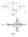
- An illustrative prior art four-capillary viscometer 10 includes four pieces of tubing or capillaries connected in a series-parallel configuration to form the hydraulic equivalent of a Wheatstone-Bridge in electronics. These tubing or capillaries in the arms of the bridge are often referred to as R1, R2, R3, and R4 because they are in effect hydraulic resistors.
- the delay unit 102 is placed in series with one of the capillaries and usually it consists of a column packed with or containing a material or solvent that will delay the sample from reaching a reference capillary while a measurement is taking place.
- This delay unit should generally provide for sufficient time or volume to accommodate the entire elution volume of the analytical GPC (Gel Permeation Chromatography) column set that is used for the separation analysis.
- GPC Gel Permeation Chromatography
- the capillary configuration is arranged such that the "bridge" is "balanced” meaning that the DP+ & DP- readings are approximately equal.
- the bridge When a delay volume is placed in series with one or more capillaries, the bridge can be balanced or rebalanced to make up for additional resistance introduced by the presence of the delay volume(s). This can be accomplished by adjusting the length(s) of one or more of the capillary tubing runs to get the bridge balance back to the manufacturing standard balance. Upon installation or during use, it may become necessary to adjust this delay volume according to the analytical column set required or analysis. One or more additional delay volumes of different sizes may therefore be shipped with the instrument or purchased to meet the specific need of the customer.
- the traditional method for balancing a viscometer bridge is to change the length of one or more of the capillary flow paths. This is accomplished by calculating the amount to subtract (or add) from a length of one or more of the capillaries. The bridge is then disassembled to make the change and reassembled by a skilled technician. This can be extremely inconvenient and may also require the instrument to be returned to the manufacturer for qualified servicing. It is also common for the balance to change due to the introduction of different solvents. These changes are typically ignored because of the inconvenience and because the length difference involved can be physically too small to allow an accurate adjustment to be accurately accomplished, and the result can be a decrease in instrument performance.
- a typical four way connector C makes connections with 1.59 mm (1/16") tubing 104.
- the tubing is pushed completely into a standard fitting 110 before a nut 106 and ferrule 108 are slid into place and tightened securely with a wrench.
- These can be over-tightened because of leaking or they may become stuck in the fitting, ruining the entire piece of tubing. Improper installation can also result in a space between one end of the tube and the fitting, creating a dead volume which can increase the band broadening of the detector.
- These connections are considered permanent, although special tools allow the nut and ferrule to be removed if the length needs to be shortened.
- US 3,302,448 discloses an apparatus for supervising the proportion of a magnetically active component in a fluid, comprising a fluid bridge having input and output connections and four conduit arms, a differential pressure sensor connected to output connections between the conduit arms for detecting a pressure difference across the sensor when the bridge is unbalanced, causing operation of a motor to open or close a fluid control device such that the bridge is balanced.
- a capillary bridge viscometer comprising: first, second, third and fourth bridge arm conduits (R1-R4), a bulkhead (122) having a supporting structure (134) supporting removable connection portions for each of a plurality of the arms in a bridge configuration and including an input port (Flow In), an output port (Flow Out), a first differential detection port (DP+) and a second differential detection port (DP-), a bridge module (124) having a supporting structure (136) supporting the bridge arm conduits (R1, R2, R3, R4) and supporting first and second further removable connection portions for each of the bridge arm conduits, wherein each of the further removable connection portions supported by the supporting structure (136) are positioned to mate with a corresponding one of the removable connection portions supported by the bulkhead supporting structure (134) concurrently to hydraulically connect the bridge arm conduits (R1-R4) in the bridge configuration; and a balance detector having hydraulic connections connected between the first and second differential detection ports (DP+, DP-) in the bridge module (124) when the removable connection
- the apparatus may further include an adjustable mechanical flow restrictor in a flow path in one of the bridge arm conduits, wherein the adjustable mechanical flow restrictor is operative to mechanically adjust a resistance to flow of a fluid while the fluid flows through the adjustable mechanical flow restrictor.
- the apparatus may further include an actuator coupled to the adjustable mechanical flow restrictor to adjust the flow rate through the adjustable mechanical flow restrictor.
- the bulkhead may include ports that are positioned to mate with corresponding connectors on the bridge, which supports the bridge conduits.
- the ports and connectors may define a set of removable connections between the bulkhead and the bridge.
- the bulkhead may be adapted to act as a pressure plate that provides even pressure on all conduits.
- the bridge supporting structure may be adapted to be removed and replaced with another bridge supporting structure.
- a kit of parts may be provided comprising a bulkhead supporting structure and a plurality of bridge supporting structures.
- the bulkhead supporting structure may define ports and conduits, which hydraulically connect them to standard fittings that connect to the bridge supporting structure to other parts of the viscometer.
- the bridge supporting structure may provide the support for the bridge arm conduits while all the remaining conduits and connections for forming the viscometer are provided by the bulkhead supporting structure.
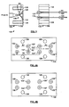
- an illustrative capillary bridge viscometer 120 includes a bulkhead 122 and a bridge module 124.
- the bulkhead includes ports 130 that are positioned to mate with corresponding hydraulic connectors 132 on the bridge module, which supports the bridge tubing.
- the ports and connectors define a set of removable connections between the bulkhead and the bridge module. This arrangement allows the bridge module to be quickly changed for different experiments or if it becomes fouled, and the bridge module can even be disposable.
- the ports are cylindrical openings in the bulkhead block and the connectors are flangeless low-pressure ferrules, such as are available from IDEX corporation of Lake Forest, IL under part number P-200NX.
- IDEX corporation of Lake Forest, IL under part number P-200NX.
- P-200NX flangeless low-pressure ferrules
- the bulkhead is built around a support 134 that defines the ports 130 and conduits 138, which hydraulically connect them to standard fittings that connect the bridge to other parts of the viscometer (e.g., 112 in Fig. 2 ).
- the bridge module is also built around a support 136 that supports the hydraulic connectors 132 and the bridge tubes R1, R2, R3, R4 that they are connected to.
- the bulkhead and bridge supports are each made of a machined block of stainless steel, but one of ordinary skill in the art would of course realize that many other suitable materials, construction techniques, and structural configurations could also be used.
- a mechanical connection can be provided between the bulkhead and the bridge module.
- the mechanical connection can be provided by four common-sized socket head screws that pass through holes 126 in the bridge module support and interact with threaded holes 128 in the bulkhead support.
- One of ordinary skill would of course recognize that many other suitable types of mechanical connections could also be used.
- the user installs the bridge module 124 on the bulkhead 122 and secures them in place mechanically by tightening the screws.
- the support acts as a pressure plate that provides even pressure on all capillaries and can eliminate the possibility of over-tightening. This installation can take place quickly without risk of confusion.
- the user can then run one or more experiments. After that, the bridge module can be removed and replaced with another and further experiments can be conducted.
- the removed bridge module can be stored, disposed of, cleaned, or returned to the manufacturer for servicing.
- bridge modules 124 can be provided to be used with the instrument. These different bridges can include different lengths and/or diameters of tubing to allow the viscometer to be used for different applications. The different bridges may also provide other differences in the hydraulic circuits that they provide. For example, the IP+ and IP- points could be made available on the bridge module instead of through the bulkhead, or the bridge module could include a built-in delay mechanism or calibration features. The bridge and bulkhead could also be split into sub-elements.
- the bulkhead in the illustrative embodiment has been designed here to yield the equivalent external plumbing connections shown in Fig. 1 with standard HPLC fittings for flow in, flow out, DP+, DP-, and one or more delay columns.
- the illustrative embodiment can also eliminate dead volume resulting from poor installation of bridge connectors.
- the illustrative embodiment can use comparable capillaries of comparable lengths and/or diameters to typical existing instruments, but one of ordinary skill in the art would recognize that other lengths and/or diameters may also be used, consistent with distances required to go from port to port.
- the modular design described in this application can be used in a variety of different kinds of instruments. It can be used in a more complex capillary viscometer that provides for eliminating break through peaks, for example, such as is described in US Pub. No. 2008/245133 (Application No. 12/072,149 ) to Titterton. Or it can be used with a mechanically balanced viscometer as provided for in an application entitled BALANCED CAPILLARY BRIDGE VISCOMETER being filed on the same date as this application. This combination can allow the bridge to be quickly balanced after a new bridge module is connected to the bulkhead.
- the modular design described in this application can also be used in other types of instruments that can benefit from the ability to make quick changes to precisely dimensioned hydraulic circuitry.
- Figure 4A shows a schematic side view of the bridge module 124 shown in Figure 3 .
- Four holes 126 are shown to connect the bridge module 124 to the bulkhead 122.
- the two hydraulic connectors 132 shown in Figure 3 are visible on the left hand side of Figure 4A .
- the remaining connectors 132', 132", 132'" that provide connections to the other bridge tubes R1, R2, R3 and R4 are positioned in the same face of the bridge module for connection to corresponding ports 130 on the bulkhead 122.
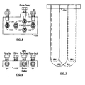
- Figure 7 shows a plan view of the path followed by the bridge tubes as represented by the dashed lines in Figure 4A .
- Figure 4B shows a similar view to Figure 4A but on the bulkhead 122.
- the bulkhead ports 130 are positioned at corresponding positions to the connectors.
- Figure 5 shows a front view of the bulkhead 122 showing the ports IP+, IP- and "From Delay”.
- Figure 5 shows the bulkhead 122 transparent to make visible the relative positions of the ports 130, 130', 130" and 130'" on the opposite side.
- Figure 6 is a top view of the bulkhead 122 to show the ports Flow In, DP+, DP- and Flow Out that are not labelled in Figure 5 for clarity.
- the viscometer 120 may include a balance detector (not shown) which is arranged to correct between the DP+ and DP- ports.
- the balance detector may include an actuator to adjust the flow rate through viscometer to balance the pressure in the viscometer
Claims (10)
- Ein Kapillarbrücken-Viskosimeter (120), das Folgendes beinhaltet:erste, zweite, dritte und vierte Brückenarmrohre (R1-R4),
eine Trennwand (122), die eine Stützkonstruktion (134) aufweist, die entfernbare Anschlussabschnitte für jedes der vier Brückenarmrohre (R1-R4) stützt, und einen Eingangsport (Flow In, Einfluss), einen Ausgangsport (Flow Out, Ausfluss), einen ersten Differenzdruckdetektionsport (DP+) und einen zweiten Differenzdruckdetektionsport (DP-) einschließt,ein Brückenmodul (124), das eine Stützkonstruktion (136) aufweist, die die Brückenarmrohre (R1, R2, R3, R4) stützt und erste und zweite weitere entfernbare Anschlussabschnitte 132, 132', 132", 132'" für jedes der vier Brückenarmrohre stützt, wobei jeder der weiteren entfernbaren Anschlussabschnitte, die von der Stützkonstruktion (136) gestützt werden, positioniert ist, um mit einem korrespondierenden der entfernbaren Anschlussabschnitte, die von der Trennwandstützkonstruktion (134) gestützt werden, zusammengeführt zu werden, um gleichzeitig die Brückenarmrohre (R1-R4) in der Brückenkonfiguration hydraulisch zu verbinden; undeinen Balancedetektor, der Hydraulikanschlüsse aufweist, die zwischen dem ersten und zweiten Differenzdruckdetektionsport (DP+, DP-) im Brückenmodul (124) verbunden sind, wenn die entfernbaren Anschlussabschnitte am Brückenmodul (124) mit korrespondierenden der entfernbaren Anschlussabschnitte, die von der Trennwandstützkonstruktion (134) gestützt werden, zusammengeführt sind. - Vorrichtung gemäß Anspruch 1, die weiter einen verstellbaren mechanischen Flussbegrenzer in einem Flussweg in einem der Brückenarmrohre (R1-R4) einschließt, wobei der verstellbare mechanische Flussbegrenzer wirksam ist, um einen Widerstand gegen den Fluss eines Fluids mechanisch zu verstellen, während das Fluid durch den verstellbaren mechanischen Flussbegrenzer fließt.
- Vorrichtung gemäß Anspruch 2, die weiter eine Betätigungseinrichtung einschließt, die am verstellbaren mechanischen Flussbegrenzer gekoppelt ist, um die Flussrate durch den verstellbaren mechanischen Flussbegrenzer zu verstellen.
- Vorrichtung gemäß Anspruch 1 oder einem der vorhergehenden Ansprüche, wobei die Trennwandstützkonstruktion (134) entfernbare Anschlussabschnitte für jeden der Eingangs- und Ausgangsports (Flow In, Flow Out) einschließt.
- Vorrichtung gemäß Anspruch 4, wobei die Trennwandstützkonstruktion (134) entfernbare Anschlussabschnitte für jeden des ersten und zweiten Differenzdruckdetektionsports (DP+, DP-) einschließt.
- Vorrichtung gemäß Anspruch 1 oder einem der vorhergehenden Ansprüche, wobei jedes der vier Brückenarmrohre (R1-R4) ein Kapillarröhrchen ist.
- Vorrichtung gemäß Anspruch 1 oder einem der vorhergehenden Ansprüche, wobei einer oder mehrere der Anschlussabschnitte eine Hülse (108) und einen Port einschließen, der dimensioniert ist, um mit der Hülse zu interagieren.
- Vorrichtung gemäß einem der Ansprüche 1 bis 7, wobei die entfernbaren Anschlussabschnitte der Trennwandstützkonstruktion (134) Folgendes einschließen:einen ersten entfernbaren Eingangsportanschluss (130), der mit dem Eingangsport (Flow In) hydraulisch verbunden und in Bezug auf die Trennwandstützkonstruktion (134) montiert ist,einen zweiten entfernbaren Eingangsportanschluss (130), der mit dem Eingangsport (Flow In) hydraulisch verbunden und in Bezug auf die Trennwandstützkonstruktion (134) montiert ist,einen ersten entfernbaren Ausgangsportanschluss (130"'), der mit dem Ausgangsport (Flow Out) hydraulisch verbunden und in Bezug auf die Trennwandstützkonstruktion (134) montiert ist,einen zweiten entfernbaren Ausgangsportanschluss (130"'), der mit dem Ausgangsport (Flow Out) hydraulisch verbunden und in Bezug auf die Trennwandstützkonstruktion (134) montiert ist,einen ersten entfernbaren ersten Differenzdruckdetektionsport (130'), der mit dem ersten Differenzdruckdetektionsport (DP+) hydraulisch verbunden und in Bezug auf die Trennwandstützkonstruktion (134) montiert ist,einen zweiten entfernbaren ersten Differenzdruckdetektionsport (130'), der mit dem ersten Differenzdruckdetektionsport (DP+) hydraulisch verbunden und in Bezug auf die Trennwandstützkonstruktion (134) montiert ist,einen ersten entfernbaren zweiten Differenzdruckdetektionsport (130"), der mit dem zweiten Differenzdruckdetektionsport (DP-) hydraulisch verbunden und in Bezug auf die Trennwandstützkonstruktion (134) montiert ist,einen zweiten entfernbaren zweiten Differenzdruckdetektionsport (130"), der mit dem zweiten Differenzdruckdetektionsport (DP-) hydraulisch verbunden und in Bezug auf die Trennwandstützkonstruktion (134) montiert ist.
- Vorrichtung gemäß Anspruch 8, wobei die Anschlüsse im Brückenmodul (124) und die Anschlüsse an der Trennwand (122) positioniert sind, um gleichzeitigen Anschluss von Folgenden zu erlauben:dem ersten entfernbaren Anschluss (132) des ersten Rohrs (R1) am ersten entfernbaren Ausgangsportanschluss (130"'),dem zweiten entfernbaren Anschluss (132') des ersten Rohrs (R1) am ersten entfernbaren zweiten Differenzdruckdetektionsportanschluss (130"),dem ersten entfernbaren Anschluss (132) des zweiten Rohrs (R2) am zweiten entfernbaren Ausgangsportanschluss (130''),dem zweiten entfernbaren Anschluss (132") des zweiten Rohrs (R2) am zweiten entfernbaren ersten Differenzdruckdetektionsportanschluss (130'),dem ersten entfernbaren Anschluss (132') des dritten Rohrs (R3) am zweiten entfernbaren zweiten Differenzdruckdetektionsportanschluss (130"),dem zweiten entfernbaren Anschluss (132"') des dritten Rohrs (R3) am zweiten entfernbaren Eingangsportanschluss (130),dem ersten entfernbaren Anschluss (132") des vierten Rohrs (R4) am ersten entfernbaren ersten Differenzdruckdetektionsportanschluss (130'), unddem zweiten entfernbaren Anschluss (132"') des vierten Rohrs (R4) am ersten entfernbaren Eingangsportanschluss (130).
- Vorrichtung gemäß Anspruch 5, wobei die entfernbaren Anschlussabschnitte für den Eingangsport (Flow In, Einfluss), Ausgangsport (Flow Out, Ausfluss), ersten Differenzdruckdetektionsport (DP+) und zweiten Differenzdruckdetektionsport (DP-) HPLC-Armaturen beinhalten.
Applications Claiming Priority (2)
| Application Number | Priority Date | Filing Date | Title |
|---|---|---|---|
| US38595510P | 2010-09-23 | 2010-09-23 | |
| PCT/GB2011/051804 WO2012038761A1 (en) | 2010-09-23 | 2011-09-23 | Modular capillary bridge viscometer |
Publications (2)
| Publication Number | Publication Date |
|---|---|
| EP2619543A1 EP2619543A1 (de) | 2013-07-31 |
| EP2619543B1 true EP2619543B1 (de) | 2014-11-05 |
Family
ID=44860433
Family Applications (1)
| Application Number | Title | Priority Date | Filing Date |
|---|---|---|---|
| EP11774083.7A Active EP2619543B1 (de) | 2010-09-23 | 2011-09-23 | Modulares kapillarbrücken-viskosimeter |
Country Status (6)
| Country | Link |
|---|---|
| US (1) | US9612183B2 (de) |
| EP (1) | EP2619543B1 (de) |
| JP (1) | JP5916734B2 (de) |
| CN (1) | CN103168223B (de) |
| IN (1) | IN2013MN00603A (de) |
| WO (1) | WO2012038761A1 (de) |
Families Citing this family (2)
| Publication number | Priority date | Publication date | Assignee | Title |
|---|---|---|---|---|
| CN103743652B (zh) * | 2013-11-16 | 2016-05-25 | 平湖市永光机械配件有限公司 | 一种粘度机的中隔板 |
| DE102014103766B4 (de) | 2014-03-19 | 2015-12-17 | Dionex Softron Gmbh | Verfahren zum Einstellen eines Gradientenverzögerungsvolumens und Verwendung einer Dosiervorrichtung |
Family Cites Families (11)
| Publication number | Priority date | Publication date | Assignee | Title |
|---|---|---|---|---|
| US3086386A (en) | 1959-09-29 | 1963-04-23 | Standard Oil Co | Viscosity measuring system |
| US3302448A (en) | 1963-09-26 | 1967-02-07 | Honeywell Inc | Apparatus for supervising the proportion of a magnetically active component in a fluid |
| US4463598A (en) * | 1982-12-10 | 1984-08-07 | Haney Max A | Capillary bridge viscometer |
| US6402703B1 (en) * | 1997-08-28 | 2002-06-11 | Visco Technologies, Inc. | Dual riser/single capillary viscometer |
| DE19846579C1 (de) | 1998-10-09 | 2000-05-25 | Collin Gmbh Dr | Vorrichtung und Verfahren zum Messen der Viskosität plastischer Massen |
| US7040144B2 (en) * | 2000-02-23 | 2006-05-09 | Caliper Life Sciences, Inc. | Microfluidic viscometer |
| US7213439B2 (en) * | 2005-03-28 | 2007-05-08 | Wyatt Technology Corporation | Automatic bridge balancing means and method for a capillary bridge viscometer |
| US7331218B2 (en) * | 2005-09-23 | 2008-02-19 | Wyatt Technology Corporation | Capillary bridge viscometer and method for measuring specific viscosity |
| US7334457B2 (en) * | 2005-10-12 | 2008-02-26 | Viscotek Corporation | Multi-capillary viscometer system and method |
| US7594428B2 (en) | 2005-10-12 | 2009-09-29 | Viscotek Corporation | Apparatus and method for eliminating the breakthrough peak in differential detectors |
| JP5200507B2 (ja) * | 2007-11-30 | 2013-06-05 | 東ソー株式会社 | 液体クロマトグラフ用粘度計 |
-
2011
- 2011-09-23 EP EP11774083.7A patent/EP2619543B1/de active Active
- 2011-09-23 CN CN201180046166.1A patent/CN103168223B/zh active Active
- 2011-09-23 US US13/825,623 patent/US9612183B2/en active Active
- 2011-09-23 WO PCT/GB2011/051804 patent/WO2012038761A1/en active Application Filing
- 2011-09-23 IN IN603MUN2013 patent/IN2013MN00603A/en unknown
- 2011-09-23 JP JP2013529713A patent/JP5916734B2/ja active Active
Also Published As
| Publication number | Publication date |
|---|---|
| CN103168223A (zh) | 2013-06-19 |
| JP2013537974A (ja) | 2013-10-07 |
| US20140060162A1 (en) | 2014-03-06 |
| IN2013MN00603A (de) | 2015-05-29 |
| CN103168223B (zh) | 2015-08-05 |
| JP5916734B2 (ja) | 2016-05-11 |
| EP2619543A1 (de) | 2013-07-31 |
| WO2012038761A1 (en) | 2012-03-29 |
| US9612183B2 (en) | 2017-04-04 |
Similar Documents
| Publication | Publication Date | Title |
|---|---|---|
| JP3487707B2 (ja) | プレーナ・マニホルド組立体及び分析機器 | |
| EP2312276A1 (de) | Verfahren zur flussmessung zusammengesetzter gasfluide und einrichtung dafür | |
| EP2619543B1 (de) | Modulares kapillarbrücken-viskosimeter | |
| US20160131617A1 (en) | Liquid flow rate measurement device | |
| US10551291B2 (en) | Balanced capillary bridge viscometry | |
| EP2407796B1 (de) | Durchflusszelle für NMR-Analysen | |
| JPH01216234A (ja) | マイクロフローセル | |
| EP2437040B1 (de) | Vorrichtung zum Messen geringer Druckdifferenzen | |
| CN107255561B (zh) | 谐波减速器静态精度测试工装及其装配方法和使用方法 | |
| JP7382070B2 (ja) | 液体クロマトグラフィー用モジュール内の統合されたカラム及び検出器 | |
| US11275061B2 (en) | Reconfigurable fluidic manifold for a liquid chromatography system | |
| EP2703809B1 (de) | Vorrichtung zur Herstellung der mobilen Phase für die Flüssigkeitschromatographie | |
| GB2558835A (en) | Systems and methods for refractive index detection | |
| CN211904537U (zh) | 一种多功能压力测量监视系统的在线检测装置 | |
| US9658194B2 (en) | Controlling interdetector band broadening | |
| CN213688581U (zh) | 一种采用平衡管路的气体流量标准装置 | |
| JP5357734B2 (ja) | 差圧計検査装置およびその使用方法 | |
| JP2010101630A (ja) | 微小流量送液装置、及び送液方法 | |
| CN219511618U (zh) | 一种用于氢气液化的质量流量计 | |
| GB2480135A (en) | Gas inlet for a process mass spectrometer | |
| CN102928626A (zh) | 一种电机测试快速对中夹紧装置 | |
| EP1196753A1 (de) | Strömungsschaltvorrichtung | |
| CN210221728U (zh) | 电影镜头扭力测试装置 | |
| JP6154623B2 (ja) | 圧力計 | |
| RU2312318C2 (ru) | Устройство для измерения силы |
Legal Events
| Date | Code | Title | Description |
|---|---|---|---|
| PUAI | Public reference made under article 153(3) epc to a published international application that has entered the european phase |
Free format text: ORIGINAL CODE: 0009012 |
|
| 17P | Request for examination filed |
Effective date: 20130108 |
|
| AK | Designated contracting states |
Kind code of ref document: A1 Designated state(s): AL AT BE BG CH CY CZ DE DK EE ES FI FR GB GR HR HU IE IS IT LI LT LU LV MC MK MT NL NO PL PT RO RS SE SI SK SM TR |
|
| DAX | Request for extension of the european patent (deleted) | ||
| 17Q | First examination report despatched |
Effective date: 20140613 |
|
| GRAP | Despatch of communication of intention to grant a patent |
Free format text: ORIGINAL CODE: EPIDOSNIGR1 |
|
| INTG | Intention to grant announced |
Effective date: 20140729 |
|
| GRAS | Grant fee paid |
Free format text: ORIGINAL CODE: EPIDOSNIGR3 |
|
| GRAA | (expected) grant |
Free format text: ORIGINAL CODE: 0009210 |
|
| AK | Designated contracting states |
Kind code of ref document: B1 Designated state(s): AL AT BE BG CH CY CZ DE DK EE ES FI FR GB GR HR HU IE IS IT LI LT LU LV MC MK MT NL NO PL PT RO RS SE SI SK SM TR |
|
| REG | Reference to a national code |
Ref country code: GB Ref legal event code: FG4D |
|
| REG | Reference to a national code |
Ref country code: CH Ref legal event code: EP |
|
| REG | Reference to a national code |
Ref country code: AT Ref legal event code: REF Ref document number: 694875 Country of ref document: AT Kind code of ref document: T Effective date: 20141115 |
|
| REG | Reference to a national code |
Ref country code: IE Ref legal event code: FG4D |
|
| REG | Reference to a national code |
Ref country code: DE Ref legal event code: R096 Ref document number: 602011011174 Country of ref document: DE Effective date: 20141224 |
|
| REG | Reference to a national code |
Ref country code: AT Ref legal event code: MK05 Ref document number: 694875 Country of ref document: AT Kind code of ref document: T Effective date: 20141105 |
|
| REG | Reference to a national code |
Ref country code: NL Ref legal event code: VDEP Effective date: 20141105 |
|
| REG | Reference to a national code |
Ref country code: LT Ref legal event code: MG4D |
|
| PG25 | Lapsed in a contracting state [announced via postgrant information from national office to epo] |
Ref country code: LT Free format text: LAPSE BECAUSE OF FAILURE TO SUBMIT A TRANSLATION OF THE DESCRIPTION OR TO PAY THE FEE WITHIN THE PRESCRIBED TIME-LIMIT Effective date: 20141105 Ref country code: NO Free format text: LAPSE BECAUSE OF FAILURE TO SUBMIT A TRANSLATION OF THE DESCRIPTION OR TO PAY THE FEE WITHIN THE PRESCRIBED TIME-LIMIT Effective date: 20150205 Ref country code: IS Free format text: LAPSE BECAUSE OF FAILURE TO SUBMIT A TRANSLATION OF THE DESCRIPTION OR TO PAY THE FEE WITHIN THE PRESCRIBED TIME-LIMIT Effective date: 20150305 Ref country code: FI Free format text: LAPSE BECAUSE OF FAILURE TO SUBMIT A TRANSLATION OF THE DESCRIPTION OR TO PAY THE FEE WITHIN THE PRESCRIBED TIME-LIMIT Effective date: 20141105 Ref country code: NL Free format text: LAPSE BECAUSE OF FAILURE TO SUBMIT A TRANSLATION OF THE DESCRIPTION OR TO PAY THE FEE WITHIN THE PRESCRIBED TIME-LIMIT Effective date: 20141105 Ref country code: ES Free format text: LAPSE BECAUSE OF FAILURE TO SUBMIT A TRANSLATION OF THE DESCRIPTION OR TO PAY THE FEE WITHIN THE PRESCRIBED TIME-LIMIT Effective date: 20141105 Ref country code: PT Free format text: LAPSE BECAUSE OF FAILURE TO SUBMIT A TRANSLATION OF THE DESCRIPTION OR TO PAY THE FEE WITHIN THE PRESCRIBED TIME-LIMIT Effective date: 20150305 |
|
| PG25 | Lapsed in a contracting state [announced via postgrant information from national office to epo] |
Ref country code: SE Free format text: LAPSE BECAUSE OF FAILURE TO SUBMIT A TRANSLATION OF THE DESCRIPTION OR TO PAY THE FEE WITHIN THE PRESCRIBED TIME-LIMIT Effective date: 20141105 Ref country code: AT Free format text: LAPSE BECAUSE OF FAILURE TO SUBMIT A TRANSLATION OF THE DESCRIPTION OR TO PAY THE FEE WITHIN THE PRESCRIBED TIME-LIMIT Effective date: 20141105 Ref country code: RS Free format text: LAPSE BECAUSE OF FAILURE TO SUBMIT A TRANSLATION OF THE DESCRIPTION OR TO PAY THE FEE WITHIN THE PRESCRIBED TIME-LIMIT Effective date: 20141105 Ref country code: HR Free format text: LAPSE BECAUSE OF FAILURE TO SUBMIT A TRANSLATION OF THE DESCRIPTION OR TO PAY THE FEE WITHIN THE PRESCRIBED TIME-LIMIT Effective date: 20141105 Ref country code: GR Free format text: LAPSE BECAUSE OF FAILURE TO SUBMIT A TRANSLATION OF THE DESCRIPTION OR TO PAY THE FEE WITHIN THE PRESCRIBED TIME-LIMIT Effective date: 20150206 Ref country code: PL Free format text: LAPSE BECAUSE OF FAILURE TO SUBMIT A TRANSLATION OF THE DESCRIPTION OR TO PAY THE FEE WITHIN THE PRESCRIBED TIME-LIMIT Effective date: 20141105 Ref country code: LV Free format text: LAPSE BECAUSE OF FAILURE TO SUBMIT A TRANSLATION OF THE DESCRIPTION OR TO PAY THE FEE WITHIN THE PRESCRIBED TIME-LIMIT Effective date: 20141105 Ref country code: CY Free format text: LAPSE BECAUSE OF FAILURE TO SUBMIT A TRANSLATION OF THE DESCRIPTION OR TO PAY THE FEE WITHIN THE PRESCRIBED TIME-LIMIT Effective date: 20141105 |
|
| PG25 | Lapsed in a contracting state [announced via postgrant information from national office to epo] |
Ref country code: EE Free format text: LAPSE BECAUSE OF FAILURE TO SUBMIT A TRANSLATION OF THE DESCRIPTION OR TO PAY THE FEE WITHIN THE PRESCRIBED TIME-LIMIT Effective date: 20141105 Ref country code: SK Free format text: LAPSE BECAUSE OF FAILURE TO SUBMIT A TRANSLATION OF THE DESCRIPTION OR TO PAY THE FEE WITHIN THE PRESCRIBED TIME-LIMIT Effective date: 20141105 Ref country code: CZ Free format text: LAPSE BECAUSE OF FAILURE TO SUBMIT A TRANSLATION OF THE DESCRIPTION OR TO PAY THE FEE WITHIN THE PRESCRIBED TIME-LIMIT Effective date: 20141105 Ref country code: DK Free format text: LAPSE BECAUSE OF FAILURE TO SUBMIT A TRANSLATION OF THE DESCRIPTION OR TO PAY THE FEE WITHIN THE PRESCRIBED TIME-LIMIT Effective date: 20141105 |
|
| REG | Reference to a national code |
Ref country code: DE Ref legal event code: R097 Ref document number: 602011011174 Country of ref document: DE |
|
| PLBE | No opposition filed within time limit |
Free format text: ORIGINAL CODE: 0009261 |
|
| STAA | Information on the status of an ep patent application or granted ep patent |
Free format text: STATUS: NO OPPOSITION FILED WITHIN TIME LIMIT |
|
| 26N | No opposition filed |
Effective date: 20150806 |
|
| PG25 | Lapsed in a contracting state [announced via postgrant information from national office to epo] |
Ref country code: IT Free format text: LAPSE BECAUSE OF FAILURE TO SUBMIT A TRANSLATION OF THE DESCRIPTION OR TO PAY THE FEE WITHIN THE PRESCRIBED TIME-LIMIT Effective date: 20141105 |
|
| PG25 | Lapsed in a contracting state [announced via postgrant information from national office to epo] |
Ref country code: SI Free format text: LAPSE BECAUSE OF FAILURE TO SUBMIT A TRANSLATION OF THE DESCRIPTION OR TO PAY THE FEE WITHIN THE PRESCRIBED TIME-LIMIT Effective date: 20141105 |
|
| PG25 | Lapsed in a contracting state [announced via postgrant information from national office to epo] |
Ref country code: LU Free format text: LAPSE BECAUSE OF FAILURE TO SUBMIT A TRANSLATION OF THE DESCRIPTION OR TO PAY THE FEE WITHIN THE PRESCRIBED TIME-LIMIT Effective date: 20150923 Ref country code: MC Free format text: LAPSE BECAUSE OF FAILURE TO SUBMIT A TRANSLATION OF THE DESCRIPTION OR TO PAY THE FEE WITHIN THE PRESCRIBED TIME-LIMIT Effective date: 20141105 |
|
| REG | Reference to a national code |
Ref country code: CH Ref legal event code: PL |
|
| PG25 | Lapsed in a contracting state [announced via postgrant information from national office to epo] |
Ref country code: RO Free format text: LAPSE BECAUSE OF FAILURE TO SUBMIT A TRANSLATION OF THE DESCRIPTION OR TO PAY THE FEE WITHIN THE PRESCRIBED TIME-LIMIT Effective date: 20141105 |
|
| REG | Reference to a national code |
Ref country code: IE Ref legal event code: MM4A |
|
| PG25 | Lapsed in a contracting state [announced via postgrant information from national office to epo] |
Ref country code: IE Free format text: LAPSE BECAUSE OF NON-PAYMENT OF DUE FEES Effective date: 20150923 Ref country code: CH Free format text: LAPSE BECAUSE OF NON-PAYMENT OF DUE FEES Effective date: 20150930 Ref country code: LI Free format text: LAPSE BECAUSE OF NON-PAYMENT OF DUE FEES Effective date: 20150930 |
|
| REG | Reference to a national code |
Ref country code: FR Ref legal event code: PLFP Year of fee payment: 6 |
|
| PG25 | Lapsed in a contracting state [announced via postgrant information from national office to epo] |
Ref country code: MT Free format text: LAPSE BECAUSE OF FAILURE TO SUBMIT A TRANSLATION OF THE DESCRIPTION OR TO PAY THE FEE WITHIN THE PRESCRIBED TIME-LIMIT Effective date: 20141105 |
|
| PG25 | Lapsed in a contracting state [announced via postgrant information from national office to epo] |
Ref country code: HU Free format text: LAPSE BECAUSE OF FAILURE TO SUBMIT A TRANSLATION OF THE DESCRIPTION OR TO PAY THE FEE WITHIN THE PRESCRIBED TIME-LIMIT; INVALID AB INITIO Effective date: 20110923 Ref country code: SM Free format text: LAPSE BECAUSE OF FAILURE TO SUBMIT A TRANSLATION OF THE DESCRIPTION OR TO PAY THE FEE WITHIN THE PRESCRIBED TIME-LIMIT Effective date: 20141105 Ref country code: BG Free format text: LAPSE BECAUSE OF FAILURE TO SUBMIT A TRANSLATION OF THE DESCRIPTION OR TO PAY THE FEE WITHIN THE PRESCRIBED TIME-LIMIT Effective date: 20141105 |
|
| REG | Reference to a national code |
Ref country code: FR Ref legal event code: PLFP Year of fee payment: 7 |
|
| PG25 | Lapsed in a contracting state [announced via postgrant information from national office to epo] |
Ref country code: BE Free format text: LAPSE BECAUSE OF FAILURE TO SUBMIT A TRANSLATION OF THE DESCRIPTION OR TO PAY THE FEE WITHIN THE PRESCRIBED TIME-LIMIT Effective date: 20141105 |
|
| PG25 | Lapsed in a contracting state [announced via postgrant information from national office to epo] |
Ref country code: MK Free format text: LAPSE BECAUSE OF FAILURE TO SUBMIT A TRANSLATION OF THE DESCRIPTION OR TO PAY THE FEE WITHIN THE PRESCRIBED TIME-LIMIT Effective date: 20141105 Ref country code: TR Free format text: LAPSE BECAUSE OF FAILURE TO SUBMIT A TRANSLATION OF THE DESCRIPTION OR TO PAY THE FEE WITHIN THE PRESCRIBED TIME-LIMIT Effective date: 20141105 |
|
| REG | Reference to a national code |
Ref country code: FR Ref legal event code: PLFP Year of fee payment: 8 |
|
| PG25 | Lapsed in a contracting state [announced via postgrant information from national office to epo] |
Ref country code: AL Free format text: LAPSE BECAUSE OF FAILURE TO SUBMIT A TRANSLATION OF THE DESCRIPTION OR TO PAY THE FEE WITHIN THE PRESCRIBED TIME-LIMIT Effective date: 20141105 |
|
| P01 | Opt-out of the competence of the unified patent court (upc) registered |
Effective date: 20230727 |
|
| PGFP | Annual fee paid to national office [announced via postgrant information from national office to epo] |
Ref country code: GB Payment date: 20230823 Year of fee payment: 13 |
|
| PGFP | Annual fee paid to national office [announced via postgrant information from national office to epo] |
Ref country code: FR Payment date: 20230822 Year of fee payment: 13 Ref country code: DE Payment date: 20230822 Year of fee payment: 13 |