EP2618063A1 - Gaskochgerät - Google Patents
Gaskochgerät Download PDFInfo
- Publication number
- EP2618063A1 EP2618063A1 EP13150845.9A EP13150845A EP2618063A1 EP 2618063 A1 EP2618063 A1 EP 2618063A1 EP 13150845 A EP13150845 A EP 13150845A EP 2618063 A1 EP2618063 A1 EP 2618063A1
- Authority
- EP
- European Patent Office
- Prior art keywords
- ignition
- gas
- clock
- button
- transformer
- Prior art date
- Legal status (The legal status is an assumption and is not a legal conclusion. Google has not performed a legal analysis and makes no representation as to the accuracy of the status listed.)
- Granted
Links
- 238000010411 cooking Methods 0.000 claims description 23
- 230000004913 activation Effects 0.000 claims description 3
- 229910000679 solder Inorganic materials 0.000 claims description 2
- 238000010304 firing Methods 0.000 claims 1
- 238000002485 combustion reaction Methods 0.000 abstract description 2
- 230000005540 biological transmission Effects 0.000 description 4
- 238000004519 manufacturing process Methods 0.000 description 3
- 238000003825 pressing Methods 0.000 description 3
- 230000000694 effects Effects 0.000 description 2
- 238000010438 heat treatment Methods 0.000 description 2
- 238000005476 soldering Methods 0.000 description 2
- 238000007792 addition Methods 0.000 description 1
- 238000000034 method Methods 0.000 description 1
Images
Classifications
-
- F—MECHANICAL ENGINEERING; LIGHTING; HEATING; WEAPONS; BLASTING
- F24—HEATING; RANGES; VENTILATING
- F24C—DOMESTIC STOVES OR RANGES ; DETAILS OF DOMESTIC STOVES OR RANGES, OF GENERAL APPLICATION
- F24C3/00—Stoves or ranges for gaseous fuels
- F24C3/12—Arrangement or mounting of control or safety devices
- F24C3/126—Arrangement or mounting of control or safety devices on ranges
- F24C3/128—Arrangement or mounting of control or safety devices on ranges in baking ovens
-
- F—MECHANICAL ENGINEERING; LIGHTING; HEATING; WEAPONS; BLASTING
- F24—HEATING; RANGES; VENTILATING
- F24C—DOMESTIC STOVES OR RANGES ; DETAILS OF DOMESTIC STOVES OR RANGES, OF GENERAL APPLICATION
- F24C3/00—Stoves or ranges for gaseous fuels
- F24C3/12—Arrangement or mounting of control or safety devices
- F24C3/124—Control panels
Definitions
- the invention relates to the ignition switch of cooking appliances, in particular of gas stoves.
- the heating or cooking operations involve successive or simultaneous stages such as gas transfer, ignition and combustion. So that the necessary heating effect can be achieved with the hobs, the gas must be passed to the burners and ignited in the gas cooking appliances.
- the gas transmission to the hob burners is made by a line under the hob. To ignite the gas provided in the burner burners are used.
- the ignition of the spark plugs that provide the gas flame is realized by the spark plugs under the gas burners and by contact transformers.
- the ignition of the spark plugs and the gas transmission to the burners is carried out by the ignition switch and provided for each hob gas switch on the front panel.
- On the front panel of the cooking appliance are in addition to the switches mentioned buttons for the regulation of the oven and a frequently executed as a digital electric clock display clock. Some cookers use the clock displays and the oven control buttons together.
- the patent application relates to the number JP58213125 a clock that is activated by turning on the main electric valve and a cooking appliance with a front panel ignition switch that fires when the main valve is open when an electromagnetic valve is turned on.
- the ignition transformer connected by a new method of assembly is an improvement needed by the related technical field.
- the present invention relates to a cooking appliance in which the ignition switch is provided on the clock, which eliminates the disadvantages of the existing systems and offers new advantages in the corresponding technical field.
- One purpose of the invention is to provide a cooking appliance in which the ignition switch is provided on the existing clock during the configuration of the cooking control panel, thus eliminating the need for an additional production step for the ignition switch.
- Another purpose of the invention is to provide a cooking utensil in which the ignition switch is mounted on the clock display during production of the cooking utensils panel without the use of additional material.
- the invention relates to a cooking appliance comprising at least one burner for gas transmission, a burner provided for the hob, at least one transformer, which is provided under the hob and gas ignition, a provided around the hob control panel and at least one provided on the control panel gas switch and a clock and provided on the clock supply socket and connected to the supply jack buttons.
- the peculiarity of the cited invention is that it includes a clock provided on the terminal, which is associated with at least one of the buttons and receives energy from the supply socket and transmits to the transformer to perform the gas ignition in the activation of this button.
- the peculiarity of a further embodiment of the invention is that it contains an ignition button associated with the terminal.
- solder channel is provided on the clock, which establishes the connection between the terminal and the ignition button.
- the peculiarity of a further embodiment of the invention is that the terminal and the transformer are connected to an additional cable.
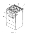
- illustration 1 shows the isometric view of a cooking appliance to which the invention has been applied.
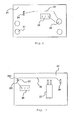
- Figure 2 shows the front perspective view of the clock of the in illustration 1 shown cooking appliance.
- Figure 3 shows the perspective rear view of the watch from the in illustration 1 shown cooking appliance.
- illustration 1 shows the overall view of a cooking appliance (10) to which the invention has been applied.
- the subject cooking appliance (10) basically includes a hob (11), under this hob (11) a designated oven (13) and between the oven (13) and the hob (11) provided control panel (12).
- On the hob (11) burner (111) are provided and the gas transmission to the mentioned burners (111) by the activation of the on the control panel (12) provided gas switch (121).
- On the said control panel (12) and a clock (20) is provided.
- the illustrated clock (20) basically shows the clock (20) and in some embodiments the control knobs (21) for the oven (13) and the ignition button (22).
- Said control knob (22) includes an electric button input (221) and an electrical button exit (222).
- the clock (20) also has a relay (23), a terminal (24), a supply socket (25) and a soldering channel (26).
- Said clamp (24) is connected to the knob outlet (222). The relevant connection takes place via the soldering channel (26).
- Said supply socket (25) is connected to said button input (221).
- the terminal (24) supplies power to the igniter ignition transformer (not shown) via the knob output (222).
- the current flow at the clock (20) as follows: From the supply socket (25) there is a current flow to the button input (221). By pressing the ignition button (22) the button input (221) and the button output (222) are bridged and there is a current flow from the knob output (222) to the terminal (24). The energy in the terminal (24) is transmitted through a cable to the transformer connected to the terminal (24) and the ignition is realized. When the ignition button (22) is released, on the other hand, the bridging between the button input and the button output (221, 222) is canceled and the ignition is interrupted due to the power interruption.
- the ignition button (22) is not provided on the control panel (12), it is at the control panel (12) except the gas buttons (121) no operation for an additional button longer necessary and beyond additions to the already existing Clock (20) Material and labor costs saved.
Landscapes
- Engineering & Computer Science (AREA)
- Chemical & Material Sciences (AREA)
- Combustion & Propulsion (AREA)
- Mechanical Engineering (AREA)
- General Engineering & Computer Science (AREA)
- Cookers (AREA)
- Electric Ovens (AREA)
- Control Of Combustion (AREA)
Abstract
Description
- Die Erfindung betrifft die Zündschalter von Kochgeräten, insbesondere von Gasherden.
- Besonders bei Kochgeräten mit Gaskochfeldern beinhalten die Erhitzungs- oder Kochvorgänge aufeinander folgende oder gleichzeitig stattfindende Stufen wie Gasübertragung, Zündung und Verbrennung. Damit bei den Kochfeldern die notwendige Heizwirkung erreicht werden kann, muss bei den Gaskochgeräten das Gas zu den Brennern geleitet und gezündet werden. Die Gasübertragung an den Kochfeldbrennern erfolgt durch eine Leitung unter dem Kochfeld. Zur Zündung des Gases dienen die im Bereich der Brenner vorgesehenen Zündkerzen. Die Zündung der Zündkerzen, die für die Gasflamme sorgen, wird durch die Zündkerzen unter den Gasbrennern und durch Kontakttransformatoren realisiert.
- Die Zündung der Zündkerzen sowie die Gasübertragung an den Brennern erfolgt durch den Zündschalter und durch für jedes Kochfeld vorgesehene Gasschalter an der Frontplatte realisiert. An der Frontplatte des Kochgeräts befinden sich neben den genannten Schaltern auch Knöpfe zur Regulierung des Backofens sowie eine häufig als digitale elektrische Uhranzeige ausgeführte Uhr. Bei einigen Herden werden die Uhranzeigen und die Bedienungsknöpfe für den Backofen zusammen verwendet.
- Durch die zunehmenden Steuerungen bei den Kochgeräten werden auf dem Bedienfeld der Kochgeräte immer mehr Knöpfe und Elemente benötigt. Dies führt zu einem zusätzlichen Arbeitsaufwand bei den Bedienfeldern, erhöht dadurch die einzusetzende Materialmenge sowie die Produktionskosten.
- In diesem Zusammenhang betrifft die Patentanmeldung mit der Nummer
JP58213125 - In diesem Zusammenhang, um die genannten Schwierigkeiten zu beseitigen und um dem entsprechenden technischen Bereich neue Vorteile anzubieten, ist der Zündtransformator, der durch eine neue Montageart angeschlossen wird, eine Verbesserung, die von dem entsprechenden technischen Bereich gebraucht wird.
- Die vorliegende Erfindung betrifft ein Kochgerät, bei dem der Zündschalter an der Uhr vorgesehen ist, der die Nachteile der bestehenden Systeme beseitigt und im entsprechenden technischen Bereich neue Vorteile bietet.
- Ein Zweck der Erfindung ist, ein Kochgerät hervorzubringen, bei dem der Zündschalter während der Konfiguration des Kochbedienfeldes auf der bestehenden Uhr vorgesehen ist und somit für den Zündschalter kein zusätzlicher Produktionsschritt mehr nötig wird.
- Ein weiterer Zweck der Erfindung ist, ein Kochgerät hervorzubringen, bei dem der Zündschalter bei der Produktion des Kochgerätebedienfeldes, ohne zusätzliches Material zu verwenden, auf der Uhranzeige angebracht wird.
- Um die genannten und aus den folgenden detaillierten Beschreibungen hervorgehende Zwecke erfüllen zu können, betrifft die Erfindung ein Kochgerät, das mindestens einen Brenner zur Gasübertragung, ein für den Brenner vorgesehenes Kochfeld, mindestens einen Transformator, der unter dem Kochfeld vorgesehen ist und zur Gaszündung dient, ein um das Kochfeld vorgesehenes Bedienfeld und mindestens einen auf dem Bedienfeld vorgesehenen Gasschalter und eine Uhr sowie auf der Uhr vorgesehene Versorgungsbuchse und an die Versorgungsbuchse angeschlossene Knöpfe enthält. Die Besonderheit der angeführten Erfindung ist, dass sie eine an der Uhr vorgesehene Klemme enthält, die mindestens einem der Knöpfe zugeordnet ist und von der Versorgungsbuchse Energie aufnimmt und auf den Transformator überträgt, um die Gaszündung bei der Aktivierung dieses Knopfes durchzuführen.
- Die Besonderheit einer weiteren Ausführung der Erfindung ist, dass sie einen der Klemme zugeordneten Zündknopf enthält.
- Die Besonderheit einer weiteren Ausführung der Erfindung ist, dass ein Lötkanal an der Uhr vorgesehen ist, der die Verbindung zwischen der Klemme und dem Zündknopf herstellt.
- Die Besonderheit einer weiteren Ausführung der Erfindung ist, dass die Klemme und der Transformator mit einem zusätzlichen Kabel verbunden sind.
-
Abbildung 1 zeigt die isometrische Ansicht eines Kochgeräts, bei dem die Erfindung angewendet wurde. -
Abbildung 2 zeigt die perspektivische Vorderansicht der Uhr von dem inAbbildung 1 dargestellten Kochgerät. -
Abbildung 3 zeigt die perspektivische Rückansicht der Uhr von dem inAbbildung 1 dargestellten Kochgerät. -
- 10
- Kochgerät
- 11
- Kochfeld
- 111
- Brenner
- 12
- Bedienfeld
- 121
- Gasschalter
- 13
- Backofen
- 20
- Uhr
- 21
- Bedienknopf
- 22
- Zündknopf
- 221
- Knopfeingang
- 222
- Knopfausgang
- 23
- Relais
- 24
- Klemme
- 25
- Versorgungsbuchse
- 26
- Lötkanal
- Bei dieser detaillierten Beschreibung wird die erfundene Neuheit zu einem besseren Verständnis des Gegenstandes, ohne eine einschränkende Wirkung zu erzielen, mit Beispielen und angefügten Abbildungen erklärt.
-
Abbildung 1 zeigt die Gesamtansicht eines Kochgeräts (10), bei dem die Erfindung angewendet wurde. Demnach beinhaltet das gegenständliche Kochgerät (10) im Grunde ein Kochfeld (11), unter diesem Kochfeld (11) einen vorgesehenen Backofen (13) und ein zwischen dem Backofen (13) und dem Kochfeld (11) vorgesehenes Bedienfeld (12). Auf dem Kochfeld (11) sind Brenner (111) vorgesehen und die Gasübertragung zu den erwähnten Brennern (111) erfolgt durch die Aktivierung der auf dem Bedienfeld (12) vorgesehenen Gasschalter (121). Auf dem genannten Bedienfeld (12) ist auch eine Uhr (20) vorgesehen. - Die in
Abbildung 2 und 3 abgebildete Uhr (20) zeigt im Grunde die Uhr (20) und in manchen Ausführungen die Bedienknöpfe (21) für den Backofen (13) und den Zündknopf (22). Der genannte Bedienknopf (22) enthält einen elektrischen Knopfeingang (221) und einen elektrischen Knopfausgang (222). Bei der Uhr (20) befinden sich außerdem ein Relais (23), eine Klemme (24), eine Versorgungsbuchse (25) und ein Lötkanal (26). - Die genannte Klemme (24) ist mit dem Knopfausgang (222) verbunden. Die betreffende Verbindung erfolgt über den Lötkanal (26). Die genannte Versorgungsbuchse (25) ist mit dem genannten Knopfeingang (221) verbunden. Die Klemme (24) versorgt über den Knopfausgang (222) den Zündtransformator für die Zündung (nicht abgebildet) mit Strom. Die Energieversorgung des Knopfeingangs (221) erfolgt über die Versorgungsbuchse (25). Durch die genannten Verbindungen wird ein Kreis geschlossen und bei einer Zündung wird an den Transformator Strom übertragen. Der Kreis wird durch das Drücken des Zündknopfes (22) geschlossen. Solange der Zündknopf (22) gedrückt wird, dauert die Transformatorzündung an und beim Loslassen des Knopfes (22) wird die Zündung unterbrochen. Der Zündknopf (22) kann durch Drücken oder durch eine andere auslösende Wirkung aktiviert werden.
- In diesem Sinne erfolgt zur Zündung des Transformators der Stromfluss an der Uhr (20) folgendermaßen: Von der Versorgungsbuchse (25) erfolgt ein Stromfluss zum Knopfeingang (221). Durch das Betätigen des Zündknopfes (22) werden der Knopfeingang (221) und der Knopfausgang (222) überbrückt und es erfolgt ein Stromfluss vom Knopfausgang (222) zur Klemme (24). Die Energie in der Klemme (24) wird durch ein Kabel zum mit der Klemme (24) verbundenen Transformator übertragen und der Zündvorgang wird realisiert. Bei Loslassen des Zündknopfs (22) hingegen wird die Überbrückung zwischen Knopfeingang und Knopfausgang (221, 222) aufgehoben und aufgrund der Stromunterbrechung wird die Zündung abgebrochen.
- Weil bei der vorliegenden Erfindung der Zündknopf (22) nicht am Bedienfeld (12) vorgesehen ist, ist es beim Bedienfeld (12) außer den Gasknöpfen (121) kein Arbeitsgang für einen zusätzlichen Knopf mehr nötig und darüber hinaus werden durch Ergänzungen an der bereits bestehenden Uhr (20) Material- und Arbeitskosten eingespart.
- Abschließend ist der Schutzumfang der Erfindung durch die Ansprüche im Anhang erläutert und kann auf keinen Fall auf diese detaillierte Beschreibung beschränkt werden, die zum Zweck der Darstellung dient. Es ist offensichtlich, dass ein Fachmann aus dem Bereich der Technik anhand der oben angeführten Details, ohne vom Hauptthema abzuweichen, neue Ausführungen hervorbringen kann.
Claims (4)
- Kochgerät (10) mit mindestens einem Brenner (111), an den Gas geleitet wird, ein Kochfeld (11) auf dem der Brenner (111) vorgesehen ist, mindestens einen unter dem Kochfeld (11) vorgesehenen Transformator, der für die Zündung des Gases im Brenner (111) dient, in der Nähe des Kochfeldes (11) vorgesehenes Bedienfeld (12) und mindestens einen auf dem Bedienfeld (12) vorgesehenen Gasschalter (121) und eine Uhr (20), an der Uhr (20) vorgesehene Versorgungsbuchse (25) und mit der Versorgungsbuchse (25) verbundene Knöpfe (21, 22), dadurch gekennzeichnet, dass das Kochgerät (10) eine an der Uhr (20) vorgesehene Klemme (24) enthält, die mit mindestens einem der Knöpfe (21, 22) verbunden ist und durch die Aktivierung der genannten Knöpfe (21, 22) von der Versorgungsbuchse (25) Energie aufnimmt und an den Transformator weiterleitet, um die Gaszündung zu gewährleisten.
- Kochgerät (10) gemäß Anspruch 1, dadurch gekennzeichnet, dass der mit der Klemme (24) verbundene Knopf (21, 22) ein Zündknopf (22) ist.
- Kochgerät (10) gemäß Anspruch 1 und 2, dadurch gekennzeichnet, dass an der Uhr (20) ein Lötkanal (26) zur Verbindung der Klemme (24) und des Zündknopfs (22) vorgesehen ist.
- Kochgerät (10) gemäß Anspruch 1, dadurch gekennzeichnet, dass die Klemme (24) mit dem Transformator durch ein zusätzliches Kabel verbunden ist.
Applications Claiming Priority (1)
| Application Number | Priority Date | Filing Date | Title |
|---|---|---|---|
| TR201200540 | 2012-01-17 |
Publications (2)
| Publication Number | Publication Date |
|---|---|
| EP2618063A1 true EP2618063A1 (de) | 2013-07-24 |
| EP2618063B1 EP2618063B1 (de) | 2018-12-19 |
Family
ID=47681652
Family Applications (1)
| Application Number | Title | Priority Date | Filing Date |
|---|---|---|---|
| EP13150845.9A Not-in-force EP2618063B1 (de) | 2012-01-17 | 2013-01-10 | Gaskochgerät |
Country Status (2)
| Country | Link |
|---|---|
| EP (1) | EP2618063B1 (de) |
| TR (1) | TR201821036T4 (de) |
Citations (2)
| Publication number | Priority date | Publication date | Assignee | Title |
|---|---|---|---|---|
| JPS58213125A (ja) | 1982-06-07 | 1983-12-12 | Matsushita Electric Ind Co Ltd | ガスオ−ブン |
| US20060234177A1 (en) * | 2005-04-19 | 2006-10-19 | Shih-Szu Yu | Time knob for gas and electric heater |
-
2013
- 2013-01-10 TR TR2018/21036T patent/TR201821036T4/tr unknown
- 2013-01-10 EP EP13150845.9A patent/EP2618063B1/de not_active Not-in-force
Patent Citations (2)
| Publication number | Priority date | Publication date | Assignee | Title |
|---|---|---|---|---|
| JPS58213125A (ja) | 1982-06-07 | 1983-12-12 | Matsushita Electric Ind Co Ltd | ガスオ−ブン |
| US20060234177A1 (en) * | 2005-04-19 | 2006-10-19 | Shih-Szu Yu | Time knob for gas and electric heater |
Also Published As
| Publication number | Publication date |
|---|---|
| EP2618063B1 (de) | 2018-12-19 |
| TR201821036T4 (tr) | 2019-01-21 |
Similar Documents
| Publication | Publication Date | Title |
|---|---|---|
| DE4003799C1 (de) | ||
| EP2160541B1 (de) | Steueranordnung für einen gasherd | |
| EP2312212B1 (de) | Gaskochstelle mit Zweikreis-Brenner | |
| DE102013218339A1 (de) | Verfahren zur Topferkennung und Gaskochfeld | |
| EP1671066B1 (de) | Gaskochstelle | |
| DE4218278C2 (de) | Vorrichtung zur Sicherung eines Gaskochstellenbrenners | |
| EP2618063B1 (de) | Gaskochgerät | |
| DE102008014841A1 (de) | Gasbrenner-Modul für ein Gaskochfeld sowie Gaskochfeld | |
| EP2837890A2 (de) | Verfahren zum Betrieb eines Gasbackofens und Gasbackofen | |
| EP1674797B1 (de) | Hausgerät | |
| EP3816517B1 (de) | Gargerätesteuerung mit betriebsartenschalter und schaltuhr | |
| DE9407567U1 (de) | Vorrichtung zur elektronischen Steuerung von Gas- und Elektrokochstellen und/oder -backöfen | |
| DE4407741A1 (de) | Sensorschalter-Einrichtung zum Ein- und Ausschalten eines elektrischen Verbrauchers | |
| DE10217008A1 (de) | Verfahren für den Betrieb eines gasbetriebenen Koch-oder Bratgeräts und Vorrichtung zur Durchführung des Verfahrens | |
| EP0598214B1 (de) | Gasherd mit einer Herdplatte aus Glaskeramik | |
| DE102005028095A1 (de) | Sicherheitssystem für ein wärmeproduzierendes Gerät, insbesondere für einen elektrischen Herd | |
| DE4104966C2 (de) | ||
| DE19620567A1 (de) | Regelelektronik mit einem Strahlungsheizkörper | |
| DE102020201610B3 (de) | Verfahren zur Ansteuerung einer Heizeinrichtung eines Kochfelds und Kochfeld | |
| DE29723914U1 (de) | Küchen-Kocheinheit | |
| DE202008016099U1 (de) | Vorrichtung zur Erwärmung von Speisen mittels wenigstens einer Gaskochstelle | |
| DE10102588B4 (de) | Kochmulde | |
| EP1505344B1 (de) | Vorrichtung zum elektrisch gesteuerten Abschalten der Gasflamme einer von mehreren Brennstellen | |
| DE102005045874A1 (de) | Verfahren zur Bedienung eines Elektrogerätes und Elektrogerät | |
| DE729358C (de) | Elektrische Anzuendevorrichtung fuer Herdfeuerungen mit einem durch den Brennstoff gebildeten Heizwiderstand |
Legal Events
| Date | Code | Title | Description |
|---|---|---|---|
| PUAI | Public reference made under article 153(3) epc to a published international application that has entered the european phase |
Free format text: ORIGINAL CODE: 0009012 |
|
| AK | Designated contracting states |
Kind code of ref document: A1 Designated state(s): AL AT BE BG CH CY CZ DE DK EE ES FI FR GB GR HR HU IE IS IT LI LT LU LV MC MK MT NL NO PL PT RO RS SE SI SK SM TR |
|
| AX | Request for extension of the european patent |
Extension state: BA ME |
|
| 17P | Request for examination filed |
Effective date: 20140124 |
|
| RBV | Designated contracting states (corrected) |
Designated state(s): AL AT BE BG CH CY CZ DE DK EE ES FI FR GB GR HR HU IE IS IT LI LT LU LV MC MK MT NL NO PL PT RO RS SE SI SK SM TR |
|
| RAP1 | Party data changed (applicant data changed or rights of an application transferred) |
Owner name: BSH HAUSGERAETE GMBH |
|
| STAA | Information on the status of an ep patent application or granted ep patent |
Free format text: STATUS: EXAMINATION IS IN PROGRESS |
|
| 17Q | First examination report despatched |
Effective date: 20170823 |
|
| GRAP | Despatch of communication of intention to grant a patent |
Free format text: ORIGINAL CODE: EPIDOSNIGR1 |
|
| STAA | Information on the status of an ep patent application or granted ep patent |
Free format text: STATUS: GRANT OF PATENT IS INTENDED |
|
| INTG | Intention to grant announced |
Effective date: 20180718 |
|
| GRAS | Grant fee paid |
Free format text: ORIGINAL CODE: EPIDOSNIGR3 |
|
| GRAA | (expected) grant |
Free format text: ORIGINAL CODE: 0009210 |
|
| STAA | Information on the status of an ep patent application or granted ep patent |
Free format text: STATUS: THE PATENT HAS BEEN GRANTED |
|
| AK | Designated contracting states |
Kind code of ref document: B1 Designated state(s): AL AT BE BG CH CY CZ DE DK EE ES FI FR GB GR HR HU IE IS IT LI LT LU LV MC MK MT NL NO PL PT RO RS SE SI SK SM TR |
|
| REG | Reference to a national code |
Ref country code: GB Ref legal event code: FG4D Free format text: NOT ENGLISH |
|
| REG | Reference to a national code |
Ref country code: CH Ref legal event code: EP |
|
| REG | Reference to a national code |
Ref country code: IE Ref legal event code: FG4D Free format text: LANGUAGE OF EP DOCUMENT: GERMAN |
|
| REG | Reference to a national code |
Ref country code: DE Ref legal event code: R096 Ref document number: 502013011822 Country of ref document: DE |
|
| REG | Reference to a national code |
Ref country code: AT Ref legal event code: REF Ref document number: 1079150 Country of ref document: AT Kind code of ref document: T Effective date: 20190115 |
|
| REG | Reference to a national code |
Ref country code: NL Ref legal event code: MP Effective date: 20181219 |
|
| PG25 | Lapsed in a contracting state [announced via postgrant information from national office to epo] |
Ref country code: BG Free format text: LAPSE BECAUSE OF FAILURE TO SUBMIT A TRANSLATION OF THE DESCRIPTION OR TO PAY THE FEE WITHIN THE PRESCRIBED TIME-LIMIT Effective date: 20190319 Ref country code: NO Free format text: LAPSE BECAUSE OF FAILURE TO SUBMIT A TRANSLATION OF THE DESCRIPTION OR TO PAY THE FEE WITHIN THE PRESCRIBED TIME-LIMIT Effective date: 20190319 Ref country code: LT Free format text: LAPSE BECAUSE OF FAILURE TO SUBMIT A TRANSLATION OF THE DESCRIPTION OR TO PAY THE FEE WITHIN THE PRESCRIBED TIME-LIMIT Effective date: 20181219 Ref country code: LV Free format text: LAPSE BECAUSE OF FAILURE TO SUBMIT A TRANSLATION OF THE DESCRIPTION OR TO PAY THE FEE WITHIN THE PRESCRIBED TIME-LIMIT Effective date: 20181219 Ref country code: HR Free format text: LAPSE BECAUSE OF FAILURE TO SUBMIT A TRANSLATION OF THE DESCRIPTION OR TO PAY THE FEE WITHIN THE PRESCRIBED TIME-LIMIT Effective date: 20181219 Ref country code: FI Free format text: LAPSE BECAUSE OF FAILURE TO SUBMIT A TRANSLATION OF THE DESCRIPTION OR TO PAY THE FEE WITHIN THE PRESCRIBED TIME-LIMIT Effective date: 20181219 |
|
| REG | Reference to a national code |
Ref country code: LT Ref legal event code: MG4D |
|
| PG25 | Lapsed in a contracting state [announced via postgrant information from national office to epo] |
Ref country code: AL Free format text: LAPSE BECAUSE OF FAILURE TO SUBMIT A TRANSLATION OF THE DESCRIPTION OR TO PAY THE FEE WITHIN THE PRESCRIBED TIME-LIMIT Effective date: 20181219 Ref country code: GR Free format text: LAPSE BECAUSE OF FAILURE TO SUBMIT A TRANSLATION OF THE DESCRIPTION OR TO PAY THE FEE WITHIN THE PRESCRIBED TIME-LIMIT Effective date: 20190320 Ref country code: SE Free format text: LAPSE BECAUSE OF FAILURE TO SUBMIT A TRANSLATION OF THE DESCRIPTION OR TO PAY THE FEE WITHIN THE PRESCRIBED TIME-LIMIT Effective date: 20181219 Ref country code: RS Free format text: LAPSE BECAUSE OF FAILURE TO SUBMIT A TRANSLATION OF THE DESCRIPTION OR TO PAY THE FEE WITHIN THE PRESCRIBED TIME-LIMIT Effective date: 20181219 |
|
| PGFP | Annual fee paid to national office [announced via postgrant information from national office to epo] |
Ref country code: TR Payment date: 20190206 Year of fee payment: 7 |
|
| PG25 | Lapsed in a contracting state [announced via postgrant information from national office to epo] |
Ref country code: NL Free format text: LAPSE BECAUSE OF FAILURE TO SUBMIT A TRANSLATION OF THE DESCRIPTION OR TO PAY THE FEE WITHIN THE PRESCRIBED TIME-LIMIT Effective date: 20181219 |
|
| PG25 | Lapsed in a contracting state [announced via postgrant information from national office to epo] |
Ref country code: CZ Free format text: LAPSE BECAUSE OF FAILURE TO SUBMIT A TRANSLATION OF THE DESCRIPTION OR TO PAY THE FEE WITHIN THE PRESCRIBED TIME-LIMIT Effective date: 20181219 Ref country code: IT Free format text: LAPSE BECAUSE OF FAILURE TO SUBMIT A TRANSLATION OF THE DESCRIPTION OR TO PAY THE FEE WITHIN THE PRESCRIBED TIME-LIMIT Effective date: 20181219 Ref country code: PL Free format text: LAPSE BECAUSE OF FAILURE TO SUBMIT A TRANSLATION OF THE DESCRIPTION OR TO PAY THE FEE WITHIN THE PRESCRIBED TIME-LIMIT Effective date: 20181219 Ref country code: ES Free format text: LAPSE BECAUSE OF FAILURE TO SUBMIT A TRANSLATION OF THE DESCRIPTION OR TO PAY THE FEE WITHIN THE PRESCRIBED TIME-LIMIT Effective date: 20181219 Ref country code: PT Free format text: LAPSE BECAUSE OF FAILURE TO SUBMIT A TRANSLATION OF THE DESCRIPTION OR TO PAY THE FEE WITHIN THE PRESCRIBED TIME-LIMIT Effective date: 20190419 |
|
| REG | Reference to a national code |
Ref country code: DE Ref legal event code: R119 Ref document number: 502013011822 Country of ref document: DE |
|
| PG25 | Lapsed in a contracting state [announced via postgrant information from national office to epo] |
Ref country code: EE Free format text: LAPSE BECAUSE OF FAILURE TO SUBMIT A TRANSLATION OF THE DESCRIPTION OR TO PAY THE FEE WITHIN THE PRESCRIBED TIME-LIMIT Effective date: 20181219 Ref country code: SM Free format text: LAPSE BECAUSE OF FAILURE TO SUBMIT A TRANSLATION OF THE DESCRIPTION OR TO PAY THE FEE WITHIN THE PRESCRIBED TIME-LIMIT Effective date: 20181219 Ref country code: IS Free format text: LAPSE BECAUSE OF FAILURE TO SUBMIT A TRANSLATION OF THE DESCRIPTION OR TO PAY THE FEE WITHIN THE PRESCRIBED TIME-LIMIT Effective date: 20190419 Ref country code: RO Free format text: LAPSE BECAUSE OF FAILURE TO SUBMIT A TRANSLATION OF THE DESCRIPTION OR TO PAY THE FEE WITHIN THE PRESCRIBED TIME-LIMIT Effective date: 20181219 Ref country code: SK Free format text: LAPSE BECAUSE OF FAILURE TO SUBMIT A TRANSLATION OF THE DESCRIPTION OR TO PAY THE FEE WITHIN THE PRESCRIBED TIME-LIMIT Effective date: 20181219 |
|
| REG | Reference to a national code |
Ref country code: CH Ref legal event code: PL |
|
| PG25 | Lapsed in a contracting state [announced via postgrant information from national office to epo] |
Ref country code: LU Free format text: LAPSE BECAUSE OF NON-PAYMENT OF DUE FEES Effective date: 20190110 |
|
| REG | Reference to a national code |
Ref country code: BE Ref legal event code: MM Effective date: 20190131 |
|
| PLBE | No opposition filed within time limit |
Free format text: ORIGINAL CODE: 0009261 |
|
| STAA | Information on the status of an ep patent application or granted ep patent |
Free format text: STATUS: NO OPPOSITION FILED WITHIN TIME LIMIT |
|
| REG | Reference to a national code |
Ref country code: IE Ref legal event code: MM4A |
|
| PG25 | Lapsed in a contracting state [announced via postgrant information from national office to epo] |
Ref country code: DE Free format text: LAPSE BECAUSE OF NON-PAYMENT OF DUE FEES Effective date: 20190801 Ref country code: DK Free format text: LAPSE BECAUSE OF FAILURE TO SUBMIT A TRANSLATION OF THE DESCRIPTION OR TO PAY THE FEE WITHIN THE PRESCRIBED TIME-LIMIT Effective date: 20181219 Ref country code: MC Free format text: LAPSE BECAUSE OF FAILURE TO SUBMIT A TRANSLATION OF THE DESCRIPTION OR TO PAY THE FEE WITHIN THE PRESCRIBED TIME-LIMIT Effective date: 20181219 |
|
| 26N | No opposition filed |
Effective date: 20190920 |
|
| GBPC | Gb: european patent ceased through non-payment of renewal fee |
Effective date: 20190319 |
|
| PG25 | Lapsed in a contracting state [announced via postgrant information from national office to epo] |
Ref country code: BE Free format text: LAPSE BECAUSE OF NON-PAYMENT OF DUE FEES Effective date: 20190131 |
|
| PG25 | Lapsed in a contracting state [announced via postgrant information from national office to epo] |
Ref country code: LI Free format text: LAPSE BECAUSE OF NON-PAYMENT OF DUE FEES Effective date: 20190131 Ref country code: CH Free format text: LAPSE BECAUSE OF NON-PAYMENT OF DUE FEES Effective date: 20190131 |
|
| PG25 | Lapsed in a contracting state [announced via postgrant information from national office to epo] |
Ref country code: IE Free format text: LAPSE BECAUSE OF NON-PAYMENT OF DUE FEES Effective date: 20190110 Ref country code: GB Free format text: LAPSE BECAUSE OF NON-PAYMENT OF DUE FEES Effective date: 20190319 |
|
| PG25 | Lapsed in a contracting state [announced via postgrant information from national office to epo] |
Ref country code: FR Free format text: LAPSE BECAUSE OF NON-PAYMENT OF DUE FEES Effective date: 20190219 Ref country code: SI Free format text: LAPSE BECAUSE OF FAILURE TO SUBMIT A TRANSLATION OF THE DESCRIPTION OR TO PAY THE FEE WITHIN THE PRESCRIBED TIME-LIMIT Effective date: 20181219 |
|
| REG | Reference to a national code |
Ref country code: AT Ref legal event code: MM01 Ref document number: 1079150 Country of ref document: AT Kind code of ref document: T Effective date: 20190110 |
|
| PG25 | Lapsed in a contracting state [announced via postgrant information from national office to epo] |
Ref country code: AT Free format text: LAPSE BECAUSE OF NON-PAYMENT OF DUE FEES Effective date: 20190110 |
|
| PG25 | Lapsed in a contracting state [announced via postgrant information from national office to epo] |
Ref country code: MT Free format text: LAPSE BECAUSE OF FAILURE TO SUBMIT A TRANSLATION OF THE DESCRIPTION OR TO PAY THE FEE WITHIN THE PRESCRIBED TIME-LIMIT Effective date: 20181219 |
|
| PG25 | Lapsed in a contracting state [announced via postgrant information from national office to epo] |
Ref country code: CY Free format text: LAPSE BECAUSE OF FAILURE TO SUBMIT A TRANSLATION OF THE DESCRIPTION OR TO PAY THE FEE WITHIN THE PRESCRIBED TIME-LIMIT Effective date: 20181219 |
|
| PG25 | Lapsed in a contracting state [announced via postgrant information from national office to epo] |
Ref country code: HU Free format text: LAPSE BECAUSE OF FAILURE TO SUBMIT A TRANSLATION OF THE DESCRIPTION OR TO PAY THE FEE WITHIN THE PRESCRIBED TIME-LIMIT; INVALID AB INITIO Effective date: 20130110 |
|
| PG25 | Lapsed in a contracting state [announced via postgrant information from national office to epo] |
Ref country code: TR Free format text: LAPSE BECAUSE OF NON-PAYMENT OF DUE FEES Effective date: 20200110 Ref country code: MK Free format text: LAPSE BECAUSE OF FAILURE TO SUBMIT A TRANSLATION OF THE DESCRIPTION OR TO PAY THE FEE WITHIN THE PRESCRIBED TIME-LIMIT Effective date: 20181219 |