EP2615690A2 - Système modulaire pour un système d'antennes à radar de niveau de remplissage - Google Patents
Système modulaire pour un système d'antennes à radar de niveau de remplissage Download PDFInfo
- Publication number
- EP2615690A2 EP2615690A2 EP13162778.8A EP13162778A EP2615690A2 EP 2615690 A2 EP2615690 A2 EP 2615690A2 EP 13162778 A EP13162778 A EP 13162778A EP 2615690 A2 EP2615690 A2 EP 2615690A2
- Authority
- EP
- European Patent Office
- Prior art keywords
- module
- antenna
- modular system
- horn
- designed
- Prior art date
- Legal status (The legal status is an assumption and is not a legal conclusion. Google has not performed a legal analysis and makes no representation as to the accuracy of the status listed.)
- Withdrawn
Links
Images


Classifications
-
- H—ELECTRICITY
- H01—ELECTRIC ELEMENTS
- H01Q—ANTENNAS, i.e. RADIO AERIALS
- H01Q1/00—Details of, or arrangements associated with, antennas
- H01Q1/12—Supports; Mounting means
- H01Q1/22—Supports; Mounting means by structural association with other equipment or articles
- H01Q1/225—Supports; Mounting means by structural association with other equipment or articles used in level-measurement devices, e.g. for level gauge measurement
-
- G—PHYSICS
- G01—MEASURING; TESTING
- G01F—MEASURING VOLUME, VOLUME FLOW, MASS FLOW OR LIQUID LEVEL; METERING BY VOLUME
- G01F23/00—Indicating or measuring liquid level or level of fluent solid material, e.g. indicating in terms of volume or indicating by means of an alarm
- G01F23/22—Indicating or measuring liquid level or level of fluent solid material, e.g. indicating in terms of volume or indicating by means of an alarm by measuring physical variables, other than linear dimensions, pressure or weight, dependent on the level to be measured, e.g. by difference of heat transfer of steam or water
- G01F23/28—Indicating or measuring liquid level or level of fluent solid material, e.g. indicating in terms of volume or indicating by means of an alarm by measuring physical variables, other than linear dimensions, pressure or weight, dependent on the level to be measured, e.g. by difference of heat transfer of steam or water by measuring the variations of parameters of electromagnetic or acoustic waves applied directly to the liquid or fluent solid material
- G01F23/284—Electromagnetic waves
-
- H—ELECTRICITY
- H01—ELECTRIC ELEMENTS
- H01Q—ANTENNAS, i.e. RADIO AERIALS
- H01Q13/00—Waveguide horns or mouths; Slot antennas; Leaky-waveguide antennas; Equivalent structures causing radiation along the transmission path of a guided wave
- H01Q13/02—Waveguide horns
-
- H—ELECTRICITY
- H01—ELECTRIC ELEMENTS
- H01Q—ANTENNAS, i.e. RADIO AERIALS
- H01Q19/00—Combinations of primary active antenna elements and units with secondary devices, e.g. with quasi-optical devices, for giving the antenna a desired directional characteristic
- H01Q19/06—Combinations of primary active antenna elements and units with secondary devices, e.g. with quasi-optical devices, for giving the antenna a desired directional characteristic using refracting or diffracting devices, e.g. lens
- H01Q19/08—Combinations of primary active antenna elements and units with secondary devices, e.g. with quasi-optical devices, for giving the antenna a desired directional characteristic using refracting or diffracting devices, e.g. lens for modifying the radiation pattern of a radiating horn in which it is located
Definitions
- the invention relates to the level measurement.
- the invention relates to a modular system for producing a level radar antenna, a level radar antenna and a level radar.
- the described embodiments relate equally to the modular system, the level radar and the Grestandsradarantenne.
- the features mentioned below with regard to the level radar antenna can also be implemented in the modular system or fill level radar, and vice versa.
- a modular system for producing a Medstandsradarantenne which has a first module and a second module.
- the first module is designed as a base antenna horn, which is filled with dielectric material and serves to feed the second module with a transmission signal.
- the second module is designed to radiate the transmission signal to a product surface, wherein the second module is an extension horn, a parabolic antenna, a filled antenna horn, an antenna horn with lens, a standpipe antenna or a rod antenna.
- an antenna system for a level radar in which a small, filled and compact antenna horn (base antenna horn) allows the coupling for various other antenna systems (the second modules) and at the same time for themselves, so without any extension, for level measurement can be used with radar.
- this antenna horn is called “base-horn”, “base antenna horn” or “base horn antenna”.
- the first module (base antenna horn) is designed for releasable connection to the second module.
- the second module it is possible for the second module to be exchanged in a simple manner if, for example, the fill level radar antenna is to be used in another measurement environment which requires, for example, a different focusing of the transmit beam.
- the first module has a first thread and the second module has a mating thread corresponding to the first thread for producing the detachable connection.
- the two modules can be screwed together.
- other types of connection are possible.
- the two modules can be connected to a flange connection.
- the two modules are connected, for example, with four screws.
- Another possibility is a plug-in connection, which then locks in a known manner.
- the modular system further comprises a third module, which is designed as a waveguide (so-called Amsterdamhohlleiter).
- the third module can also be connected to the first module via a detachable connection.
- the first module has a waveguide section, via which the transmission signal from the source, for example, an electronic module of the level radar, is supplied.
- the waveguide and / or the waveguide section of the first module is provided with a glass window which has a thickness which corresponds approximately to an integer multiple of half the wavelength of the transmission signal.
- a dielectric with a lower dielectric constant ie a low dielectric constant.
- PTFE is suitable for this purpose.
- the coating each has an approximate thickness of ⁇ / 4 of the material used. For example, with two ⁇ / 4-thick PTFE disks, the bandwidth of the glass window almost doubles.
- the second module is designed as a Cassegrain antenna. It is therefore a special form of parabolic antenna.
- the first module has a lens which is arranged between the first module and the second module.
- the lens is designed for coupling the transmission signal into the second module.
- the modular system is designed for frequencies of the transmission signal in the range between 75 GHz and 110 GHz. It can also be designed for frequencies below 75 GHz or above 110 GHz.
- the transition between the first module and the second module or the transition between the first module and the third module is designed without gaps, so that the second module starts directly at the Ante en Stahl of the first module or the third module connects directly to the first module.
- a Medstandsradarantenne which has a first module and a second module of a modular system described above.
- a fill level radar is specified with a fill level radar antenna which has a first module and a second module of a modular system described above.
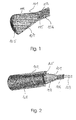
- Fig. 1 shows a sectional view of a base antenna horn 101.
- the base antenna horn 101 has an antenna housing 113, 114 on.
- the region of the housing 114 is conical, so that it forms an antenna funnel, which is at least partially filled with a dielectric material 107.
- the region 113 is made cylindrical so as to form a waveguide portion 106. Into the waveguide section 106 projects a tapered tip 115 of the dielectric filling 107.
- a lens 105 is provided, which also consists of dielectric material.
- the lens 105, the antenna fill 107, and the conical tip 115 may be integrally molded.
- these three elements 105, 107 and 115 may be juxtaposed and made of different materials.
- the base horn 101 is the central element, ie the basis of the modular system. It is designed so that it can be used to feed all other antenna types or antenna extensions, which are specified in more detail below. In addition, it can already be used for level measurement, even without extension in any form. This has the advantage that on the one hand can be measured even in very small e mentalrö Anlagenen and on the other depending on the requirements, application and space different extensions can be attached.
- the level radar antenna created from the individual modules is used in the W band.
- the W band ranges from 75 GHz to 110 GHz.
- the Gresradarantenne at a center frequency of 79 GHz can be used.
- the frequency of 79 GHz is also in the so-called E-band, which ranges from 60 GHz to 90 GHz, as these "standard bands" overlap.
- the antenna horn 114 would have an optimal length of about 110 mm.
- a dielectric material for example, polytetrafluoroethylene (PTFE) or polypropylene (PP)
- PTFE polytetrafluoroethylene
- PP polypropylene
- the horn length can be reduced to about one quarter, ie 25 to 30 mm.
- the lens may have any shape and may in particular be made of a different dielectric material, as long as it works as a converging lens or as a convex lens.
- the lens is spherical, aspheric or a Fresnel lens.
- the lens may be cone-shaped.
- the attachment of the lens in a corresponding form achieves an improved dripping behavior of condensate adhesions.
- the asi-horn 101 itself is formed on the non-radiating side with a waveguide 106, 113 which may be filled or unfilled. If the waveguide is unfilled, the dielectric fill 107 of the antenna horn 114 may leak into the waveguide 106. This is shown by the tip 115.
- the dielectric filling may be formed as far as the notional tip of the cone formed by the conical horn.
- the tip in the waveguide can also assume an angle other than the opening angle of the antenna funnel 114.
- the waveguide in the conical horn is designed as a circular waveguide.
- the waveguide can also be another form, for. B. oval or rectangular, suppose.
- this Waveguide 106, 113 the microwave signals from the electronics or radio frequency unit 805 and / or decoupled (see Fig. 8 ).
- the waveguide 106 or an adjoining waveguide 103 may be equipped with a glass window 104 (see, for example Fig. 5A ).
- This glass window serves as a zone-separating element.
- the glass window has the thickness of half lambda or a multiple thereof for optimum function.
- Lambda is the wavelength of the transmission signal (relative to the center frequency of the system).
- the lambda half value refers to the dielectric constant of the glass used for the window, ie is half the wavelength of the transmission signal within the glass window.
- the glass window can be coated on one or both sides with a dielectric with a lower dielectric constant.
- a dielectric with a lower dielectric constant As a material for this purpose, for example, PTFE is suitable.
- the assembly can be done for example by sticking to the glass.
- the thickness of this dielectric should be for optimal function lambda quarter.
- Lambda is also the wavelength of the transmission signal relative to the center frequency of the system.
- the value lambda-quarter refers to the dielectric constant of the material used for the coating, that is one quarter of the wavelength of the transmission signal within the glass window coating used.
- the installation of the glass window can, as in the Fig. 5A, 6th . 7A shown at the top of the waveguide element 106 executed.
- the attachment of the glass window on the waveguide 106 for example, by means of a weld, but can also be realized with a circumferential thread.
- the base horn 101 can be used directly for measurement in the process. Furthermore, it can also be used for coupling with other antennas be used. In the following, various additional modular modules will be described, to which the base antenna horn 101 can be connected.
- Fig. 2 shows a sectional view of a base antenna horn 101, which is connected at its front to an expansion horn 102 and which is connected at its rear to a waveguide 103.
- the asi-horn 101 is thus used for coupling into the expansion horn 102.
- the extension horn 102 may be made shorter than if it were widened directly from the waveguide 103 to the extension horn 102 (that is, the extension horn would be connected directly to the waveguide 103).
- the expansion horn 102 is conical inside 108.
- the interior 108 of the extension horn 102 may be "empty" or partially or completely filled with a dielectric material.
- the waveguide 103 is screwed to the waveguide section 106 of the base horn 101, for example, so that it can be easily released again.
- the waveguide 106 of the base horn 101 may also be connected directly to the electronics of the level radar.
- Fig. 3 shows an enlarged view of a portion of the arrangement according to Fig. 2 ,
- the transition 301 between the base horn 101 and the extension horn 102 is performed gap-free and the expansion horn 102 begins directly at the end of the antenna filling or the lens 105th
- extension horn 102 on the asishorn 101, for example, via a thread.
- the extension horn is then simply screwed onto the base mandrel.
- connection can be connected to a flange connection.
- the two modules are connected, for example, with four screws.
- Another possibility would be a plug-in connection, which then locks in some way.
- Fig. 4 shows a further embodiment in which the base horn 101 is used for coupling into a Cassegrain parabolic antenna.
- the parabolic antenna 109 has a conical reflector 110, a parabolic mirror 111 and an antenna collar 112.
- the arrows 401, 402 symbolize the transmission signal.
- the ratio between the focal length f and the diameter D (f / D ratio) of the parabolic mirror is, for example, 0.27, so that the sub-reflector 110 lies within the mirror or inside the mirror and its mirror edge 112.
- Such an arrangement is for example in the EP 1619747 A1 shown.
- the subreflector 110 is hyperpolished. But it can also take other forms, such as a cone shape.
- the attachment of the subreflector for example, with two or more webs, which are fixed within the parabolic mirror or at the edge of the mirror.
- This attachment can z. B. done by welding.
- the transition from the horn antenna 101 1 to the parabolic mirror 109 takes place, for example, without gaps.
- the base horn 101 may be used for coupling into another filled antenna horn.
- the so-called expansion horn 102 is also filled with one or more different dielectric materials.
- a lens is attached at its end.
- the lens may have any shape as long as it works only as a converging lens or as a convex lens. For example, it is spherical, aspherical, or designed as a Fresnel lens or simplified only conical.
- the antenna system can be shortened again.
- the lens shape provides improved dripping behavior in the case of condensate deposits.
- the base horn can be used for coupling into a larger horn with lens.
- extension horn remains unfilled.
- a converging lens of dielectric material to shorten the antenna length.
- the base horn can be used for coupling into a standpipe antenna or a rod antenna.
- Fig. 5A shows a sectional view of a base antenna 101 according to an embodiment of the invention.
- the antenna housing 501 is made in one piece.
- the filling 506, 507 of the antenna is inserted together with the lens 105 from the front into the housing 501 and mounted therein. Attached and held the filling of a front-bolted retaining ring 508.
- This retaining ring 508 is in detail in Fig. 5B displayed.
- the retaining ring 508 is mounted, for example by means of a thread. Also, the retaining ring 508 may be made of a flexible material. In this case, it can be clicked on the housing 501. Also, it can be glued or welded to the housing.
- sealing rings 502, 503, 504 are provided, which are inserted into corresponding annular recesses 505 of the housing.
- the dielectric filling of the antenna horn has, in addition to the lens 105, two further regions 506, 507.
- the region 506 is cylindrical, the region 507 is conical and protrudes with its tip into the waveguide section 106 of the base antenna 101.
- the cylindrical region 504 can also be completely eliminated, so that the filling is only conical.
- the seals are also arranged in this case only in the conical region.
- the glass window 104 is shown, which is fitted in a corresponding recess of a support plate 509.
- the carrier plate 509 is located in a corresponding recess of the housing 501.
- the filling 506, 507 with the lens 105 may be made in one piece or in two or three parts.
- the retaining ring 508 is used in particular in the case of a multi-part embodiment of the filling 506, 507, 105 to press the individual parts together.
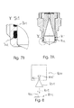
- Fig. 6 and 7A, 7B show two further embodiments of the base mandrel 101, in which the antenna filling from behind (that is, from the side facing the electronics) is mounted and bolted.
- the antenna filling is carried out in one or two parts.
- FIGS. 7A, 7B show different possibilities of O-ring mounting of the sealing rings 502, 503, 504 and 701, 702, respectively.
- two O-rings 502, 503 are arranged in the region of the conical portion of the filling, whereas a third O-ring 504 is arranged in the region of the cylindrical portion of the filling (see Fig. 6 ).
- the O-rings 701, 702 can be arranged only in the cylindrical region of the filling (see Fig. 7A, 7B ).
- puncture for an O-ring may be partially or completely filled rather than in the antenna horn.
- Puncture is a recess (groove), in which the O-ring is located, as in the Fig. 5B pictured is to be understood.
- an element 603 is inserted into the housing 604, which forms the actual antenna horn.
- the housing is in contrast to the embodiment of Fig. 5A several parts.
- the element 603 consists e.g. made of metal, preferably stainless steel or aluminum. It is also possible to use a plastic such as PBT (VALOX with glass fiber), which is metallized at least on the inner contour.
- PBT VALOX with glass fiber
- the housing 604 is also made of metal, preferably stainless steel.
- Fig. 7B shows an enlarged detail of the section Y of Fig. 7A .
- the magnification scale is, as in the Fig. 5B, 5 : 1 ,
- thermoplastic so for example Perfluoralkoxypolymer (PFA).
- PFA Perfluoralkoxypolymer
- Fig. 8 shows a level radar 800 with a level radar antenna 801 having a first and second module described above. Furthermore, a waveguide 103 is provided which connects the antenna 801 to an electronics 805.
- the antenna 801 transmits a transmission signal 802 in the direction of the product surface 804, from which a corresponding return signal 803 is reflected and then picked up by the antenna 801.
Landscapes
- Physics & Mathematics (AREA)
- Electromagnetism (AREA)
- Thermal Sciences (AREA)
- Fluid Mechanics (AREA)
- General Physics & Mathematics (AREA)
- Aerials With Secondary Devices (AREA)
- Waveguide Aerials (AREA)
Priority Applications (1)
| Application Number | Priority Date | Filing Date | Title |
|---|---|---|---|
| EP13162778.8A EP2615690A3 (fr) | 2008-09-15 | 2008-09-15 | Système modulaire pour un système d'antennes à radar de niveau de remplissage |
Applications Claiming Priority (2)
| Application Number | Priority Date | Filing Date | Title |
|---|---|---|---|
| EP08164367A EP2184807A1 (fr) | 2008-09-15 | 2008-09-15 | Système modulaire pour un système d'antennes à radar de niveau de remplissage |
| EP13162778.8A EP2615690A3 (fr) | 2008-09-15 | 2008-09-15 | Système modulaire pour un système d'antennes à radar de niveau de remplissage |
Related Parent Applications (2)
| Application Number | Title | Priority Date | Filing Date |
|---|---|---|---|
| EP08164367A Division EP2184807A1 (fr) | 2008-09-15 | 2008-09-15 | Système modulaire pour un système d'antennes à radar de niveau de remplissage |
| EP08164367.8 Division | 2008-09-15 |
Publications (2)
| Publication Number | Publication Date |
|---|---|
| EP2615690A2 true EP2615690A2 (fr) | 2013-07-17 |
| EP2615690A3 EP2615690A3 (fr) | 2014-03-26 |
Family
ID=40239567
Family Applications (2)
| Application Number | Title | Priority Date | Filing Date |
|---|---|---|---|
| EP08164367A Withdrawn EP2184807A1 (fr) | 2008-09-15 | 2008-09-15 | Système modulaire pour un système d'antennes à radar de niveau de remplissage |
| EP13162778.8A Withdrawn EP2615690A3 (fr) | 2008-09-15 | 2008-09-15 | Système modulaire pour un système d'antennes à radar de niveau de remplissage |
Family Applications Before (1)
| Application Number | Title | Priority Date | Filing Date |
|---|---|---|---|
| EP08164367A Withdrawn EP2184807A1 (fr) | 2008-09-15 | 2008-09-15 | Système modulaire pour un système d'antennes à radar de niveau de remplissage |
Country Status (3)
| Country | Link |
|---|---|
| US (1) | US7940207B1 (fr) |
| EP (2) | EP2184807A1 (fr) |
| CN (1) | CN101677147B (fr) |
Families Citing this family (178)
| Publication number | Priority date | Publication date | Assignee | Title |
|---|---|---|---|---|
| JP5555087B2 (ja) * | 2010-07-30 | 2014-07-23 | 株式会社豊田中央研究所 | レーダ装置 |
| EP2469654B1 (fr) * | 2010-12-21 | 2014-08-27 | Siemens Aktiengesellschaft | Antenne à cornet pour dispositif radar |
| US8797207B2 (en) * | 2011-04-18 | 2014-08-05 | Vega Grieshaber Kg | Filling level measuring device antenna cover |
| DE102012003398B4 (de) * | 2012-02-23 | 2015-06-25 | Krohne Messtechnik Gmbh | Nach dem Radar-Prinzip arbeitendes Füllstandsmessgerät |
| US20140007674A1 (en) * | 2012-07-04 | 2014-01-09 | Vega Grieshaber Kg | Gas-tight waveguide coupling, high-frequency module, fill-level radar and use |
| US9113347B2 (en) | 2012-12-05 | 2015-08-18 | At&T Intellectual Property I, Lp | Backhaul link for distributed antenna system |
| US10009065B2 (en) | 2012-12-05 | 2018-06-26 | At&T Intellectual Property I, L.P. | Backhaul link for distributed antenna system |
| EP2752941A1 (fr) * | 2013-01-03 | 2014-07-09 | VEGA Grieshaber KG | Antenne parabolique ayant un sous-réflecteur intégré dans le radôme |
| CN104109540A (zh) * | 2013-04-18 | 2014-10-22 | 宝山钢铁股份有限公司 | 干熄焦炉微波料位检测装置 |
| US9525524B2 (en) | 2013-05-31 | 2016-12-20 | At&T Intellectual Property I, L.P. | Remote distributed antenna system |
| US9999038B2 (en) | 2013-05-31 | 2018-06-12 | At&T Intellectual Property I, L.P. | Remote distributed antenna system |
| DE102013106978A1 (de) * | 2013-07-03 | 2015-01-22 | Endress + Hauser Gmbh + Co. Kg | Antennenanordnung für ein Füllstandsmessgerät |
| US9246227B2 (en) * | 2013-07-28 | 2016-01-26 | Finetek Co., Ltd. | Horn antenna device and step-shaped signal feed-in apparatus thereof |
| US8897697B1 (en) | 2013-11-06 | 2014-11-25 | At&T Intellectual Property I, Lp | Millimeter-wave surface-wave communications |
| US9209902B2 (en) | 2013-12-10 | 2015-12-08 | At&T Intellectual Property I, L.P. | Quasi-optical coupler |
| US9404787B2 (en) * | 2014-02-26 | 2016-08-02 | Finetek Co., Ltd. | Level measuring device with an integratable lens antenna |
| US9882285B2 (en) * | 2014-04-24 | 2018-01-30 | Honeywell International Inc. | Dielectric hollow antenna |
| US9692101B2 (en) | 2014-08-26 | 2017-06-27 | At&T Intellectual Property I, L.P. | Guided wave couplers for coupling electromagnetic waves between a waveguide surface and a surface of a wire |
| US9768833B2 (en) | 2014-09-15 | 2017-09-19 | At&T Intellectual Property I, L.P. | Method and apparatus for sensing a condition in a transmission medium of electromagnetic waves |
| US10063280B2 (en) | 2014-09-17 | 2018-08-28 | At&T Intellectual Property I, L.P. | Monitoring and mitigating conditions in a communication network |
| US9615269B2 (en) | 2014-10-02 | 2017-04-04 | At&T Intellectual Property I, L.P. | Method and apparatus that provides fault tolerance in a communication network |
| US9685992B2 (en) | 2014-10-03 | 2017-06-20 | At&T Intellectual Property I, L.P. | Circuit panel network and methods thereof |
| US9503189B2 (en) | 2014-10-10 | 2016-11-22 | At&T Intellectual Property I, L.P. | Method and apparatus for arranging communication sessions in a communication system |
| US9762289B2 (en) | 2014-10-14 | 2017-09-12 | At&T Intellectual Property I, L.P. | Method and apparatus for transmitting or receiving signals in a transportation system |
| US9973299B2 (en) | 2014-10-14 | 2018-05-15 | At&T Intellectual Property I, L.P. | Method and apparatus for adjusting a mode of communication in a communication network |
| US9520945B2 (en) | 2014-10-21 | 2016-12-13 | At&T Intellectual Property I, L.P. | Apparatus for providing communication services and methods thereof |
| US9653770B2 (en) | 2014-10-21 | 2017-05-16 | At&T Intellectual Property I, L.P. | Guided wave coupler, coupling module and methods for use therewith |
| US9312919B1 (en) | 2014-10-21 | 2016-04-12 | At&T Intellectual Property I, Lp | Transmission device with impairment compensation and methods for use therewith |
| US9769020B2 (en) | 2014-10-21 | 2017-09-19 | At&T Intellectual Property I, L.P. | Method and apparatus for responding to events affecting communications in a communication network |
| US9780834B2 (en) | 2014-10-21 | 2017-10-03 | At&T Intellectual Property I, L.P. | Method and apparatus for transmitting electromagnetic waves |
| US9627768B2 (en) | 2014-10-21 | 2017-04-18 | At&T Intellectual Property I, L.P. | Guided-wave transmission device with non-fundamental mode propagation and methods for use therewith |
| US9577306B2 (en) | 2014-10-21 | 2017-02-21 | At&T Intellectual Property I, L.P. | Guided-wave transmission device and methods for use therewith |
| US9544006B2 (en) | 2014-11-20 | 2017-01-10 | At&T Intellectual Property I, L.P. | Transmission device with mode division multiplexing and methods for use therewith |
| US9997819B2 (en) | 2015-06-09 | 2018-06-12 | At&T Intellectual Property I, L.P. | Transmission medium and method for facilitating propagation of electromagnetic waves via a core |
| US10009067B2 (en) | 2014-12-04 | 2018-06-26 | At&T Intellectual Property I, L.P. | Method and apparatus for configuring a communication interface |
| US9800327B2 (en) | 2014-11-20 | 2017-10-24 | At&T Intellectual Property I, L.P. | Apparatus for controlling operations of a communication device and methods thereof |
| US10243784B2 (en) | 2014-11-20 | 2019-03-26 | At&T Intellectual Property I, L.P. | System for generating topology information and methods thereof |
| US9680670B2 (en) | 2014-11-20 | 2017-06-13 | At&T Intellectual Property I, L.P. | Transmission device with channel equalization and control and methods for use therewith |
| US9954287B2 (en) | 2014-11-20 | 2018-04-24 | At&T Intellectual Property I, L.P. | Apparatus for converting wireless signals and electromagnetic waves and methods thereof |
| US10340573B2 (en) | 2016-10-26 | 2019-07-02 | At&T Intellectual Property I, L.P. | Launcher with cylindrical coupling device and methods for use therewith |
| US9461706B1 (en) | 2015-07-31 | 2016-10-04 | At&T Intellectual Property I, Lp | Method and apparatus for exchanging communication signals |
| US9654173B2 (en) | 2014-11-20 | 2017-05-16 | At&T Intellectual Property I, L.P. | Apparatus for powering a communication device and methods thereof |
| US9742462B2 (en) | 2014-12-04 | 2017-08-22 | At&T Intellectual Property I, L.P. | Transmission medium and communication interfaces and methods for use therewith |
| US10144036B2 (en) | 2015-01-30 | 2018-12-04 | At&T Intellectual Property I, L.P. | Method and apparatus for mitigating interference affecting a propagation of electromagnetic waves guided by a transmission medium |
| US9876570B2 (en) | 2015-02-20 | 2018-01-23 | At&T Intellectual Property I, Lp | Guided-wave transmission device with non-fundamental mode propagation and methods for use therewith |
| US9749013B2 (en) | 2015-03-17 | 2017-08-29 | At&T Intellectual Property I, L.P. | Method and apparatus for reducing attenuation of electromagnetic waves guided by a transmission medium |
| US9705561B2 (en) | 2015-04-24 | 2017-07-11 | At&T Intellectual Property I, L.P. | Directional coupling device and methods for use therewith |
| US10224981B2 (en) | 2015-04-24 | 2019-03-05 | At&T Intellectual Property I, Lp | Passive electrical coupling device and methods for use therewith |
| US9793954B2 (en) | 2015-04-28 | 2017-10-17 | At&T Intellectual Property I, L.P. | Magnetic coupling device and methods for use therewith |
| US9948354B2 (en) | 2015-04-28 | 2018-04-17 | At&T Intellectual Property I, L.P. | Magnetic coupling device with reflective plate and methods for use therewith |
| US9490869B1 (en) | 2015-05-14 | 2016-11-08 | At&T Intellectual Property I, L.P. | Transmission medium having multiple cores and methods for use therewith |
| US9748626B2 (en) | 2015-05-14 | 2017-08-29 | At&T Intellectual Property I, L.P. | Plurality of cables having different cross-sectional shapes which are bundled together to form a transmission medium |
| US9871282B2 (en) | 2015-05-14 | 2018-01-16 | At&T Intellectual Property I, L.P. | At least one transmission medium having a dielectric surface that is covered at least in part by a second dielectric |
| US10650940B2 (en) | 2015-05-15 | 2020-05-12 | At&T Intellectual Property I, L.P. | Transmission medium having a conductive material and methods for use therewith |
| US9917341B2 (en) | 2015-05-27 | 2018-03-13 | At&T Intellectual Property I, L.P. | Apparatus and method for launching electromagnetic waves and for modifying radial dimensions of the propagating electromagnetic waves |
| US9866309B2 (en) | 2015-06-03 | 2018-01-09 | At&T Intellectual Property I, Lp | Host node device and methods for use therewith |
| US10812174B2 (en) | 2015-06-03 | 2020-10-20 | At&T Intellectual Property I, L.P. | Client node device and methods for use therewith |
| US10103801B2 (en) | 2015-06-03 | 2018-10-16 | At&T Intellectual Property I, L.P. | Host node device and methods for use therewith |
| US9912381B2 (en) | 2015-06-03 | 2018-03-06 | At&T Intellectual Property I, Lp | Network termination and methods for use therewith |
| US9913139B2 (en) | 2015-06-09 | 2018-03-06 | At&T Intellectual Property I, L.P. | Signal fingerprinting for authentication of communicating devices |
| US10142086B2 (en) | 2015-06-11 | 2018-11-27 | At&T Intellectual Property I, L.P. | Repeater and methods for use therewith |
| US9608692B2 (en) | 2015-06-11 | 2017-03-28 | At&T Intellectual Property I, L.P. | Repeater and methods for use therewith |
| US9820146B2 (en) | 2015-06-12 | 2017-11-14 | At&T Intellectual Property I, L.P. | Method and apparatus for authentication and identity management of communicating devices |
| US9667317B2 (en) | 2015-06-15 | 2017-05-30 | At&T Intellectual Property I, L.P. | Method and apparatus for providing security using network traffic adjustments |
| US9640850B2 (en) | 2015-06-25 | 2017-05-02 | At&T Intellectual Property I, L.P. | Methods and apparatus for inducing a non-fundamental wave mode on a transmission medium |
| US9865911B2 (en) | 2015-06-25 | 2018-01-09 | At&T Intellectual Property I, L.P. | Waveguide system for slot radiating first electromagnetic waves that are combined into a non-fundamental wave mode second electromagnetic wave on a transmission medium |
| US9509415B1 (en) | 2015-06-25 | 2016-11-29 | At&T Intellectual Property I, L.P. | Methods and apparatus for inducing a fundamental wave mode on a transmission medium |
| DE102015111289B4 (de) * | 2015-07-13 | 2023-03-30 | Endress+Hauser SE+Co. KG | Antennen-Einheit für ein Radar-basiertes Füllstandsmessgerät und Füllstandsmessgerät |
| US10033108B2 (en) | 2015-07-14 | 2018-07-24 | At&T Intellectual Property I, L.P. | Apparatus and methods for generating an electromagnetic wave having a wave mode that mitigates interference |
| US10044409B2 (en) | 2015-07-14 | 2018-08-07 | At&T Intellectual Property I, L.P. | Transmission medium and methods for use therewith |
| US10341142B2 (en) | 2015-07-14 | 2019-07-02 | At&T Intellectual Property I, L.P. | Apparatus and methods for generating non-interfering electromagnetic waves on an uninsulated conductor |
| US10205655B2 (en) | 2015-07-14 | 2019-02-12 | At&T Intellectual Property I, L.P. | Apparatus and methods for communicating utilizing an antenna array and multiple communication paths |
| US10129057B2 (en) | 2015-07-14 | 2018-11-13 | At&T Intellectual Property I, L.P. | Apparatus and methods for inducing electromagnetic waves on a cable |
| US9722318B2 (en) | 2015-07-14 | 2017-08-01 | At&T Intellectual Property I, L.P. | Method and apparatus for coupling an antenna to a device |
| US10790593B2 (en) | 2015-07-14 | 2020-09-29 | At&T Intellectual Property I, L.P. | Method and apparatus including an antenna comprising a lens and a body coupled to a feedline having a structure that reduces reflections of electromagnetic waves |
| US10033107B2 (en) | 2015-07-14 | 2018-07-24 | At&T Intellectual Property I, L.P. | Method and apparatus for coupling an antenna to a device |
| US10148016B2 (en) | 2015-07-14 | 2018-12-04 | At&T Intellectual Property I, L.P. | Apparatus and methods for communicating utilizing an antenna array |
| US10170840B2 (en) | 2015-07-14 | 2019-01-01 | At&T Intellectual Property I, L.P. | Apparatus and methods for sending or receiving electromagnetic signals |
| US10320586B2 (en) | 2015-07-14 | 2019-06-11 | At&T Intellectual Property I, L.P. | Apparatus and methods for generating non-interfering electromagnetic waves on an insulated transmission medium |
| US9628116B2 (en) | 2015-07-14 | 2017-04-18 | At&T Intellectual Property I, L.P. | Apparatus and methods for transmitting wireless signals |
| US9853342B2 (en) | 2015-07-14 | 2017-12-26 | At&T Intellectual Property I, L.P. | Dielectric transmission medium connector and methods for use therewith |
| US9847566B2 (en) | 2015-07-14 | 2017-12-19 | At&T Intellectual Property I, L.P. | Method and apparatus for adjusting a field of a signal to mitigate interference |
| US10439290B2 (en) | 2015-07-14 | 2019-10-08 | At&T Intellectual Property I, L.P. | Apparatus and methods for wireless communications |
| US9836957B2 (en) | 2015-07-14 | 2017-12-05 | At&T Intellectual Property I, L.P. | Method and apparatus for communicating with premises equipment |
| US10511346B2 (en) | 2015-07-14 | 2019-12-17 | At&T Intellectual Property I, L.P. | Apparatus and methods for inducing electromagnetic waves on an uninsulated conductor |
| US9882257B2 (en) | 2015-07-14 | 2018-01-30 | At&T Intellectual Property I, L.P. | Method and apparatus for launching a wave mode that mitigates interference |
| US9793951B2 (en) | 2015-07-15 | 2017-10-17 | At&T Intellectual Property I, L.P. | Method and apparatus for launching a wave mode that mitigates interference |
| US9608740B2 (en) | 2015-07-15 | 2017-03-28 | At&T Intellectual Property I, L.P. | Method and apparatus for launching a wave mode that mitigates interference |
| US10090606B2 (en) | 2015-07-15 | 2018-10-02 | At&T Intellectual Property I, L.P. | Antenna system with dielectric array and methods for use therewith |
| US9912027B2 (en) | 2015-07-23 | 2018-03-06 | At&T Intellectual Property I, L.P. | Method and apparatus for exchanging communication signals |
| US9871283B2 (en) | 2015-07-23 | 2018-01-16 | At&T Intellectual Property I, Lp | Transmission medium having a dielectric core comprised of plural members connected by a ball and socket configuration |
| US9948333B2 (en) | 2015-07-23 | 2018-04-17 | At&T Intellectual Property I, L.P. | Method and apparatus for wireless communications to mitigate interference |
| US9749053B2 (en) | 2015-07-23 | 2017-08-29 | At&T Intellectual Property I, L.P. | Node device, repeater and methods for use therewith |
| US10784670B2 (en) | 2015-07-23 | 2020-09-22 | At&T Intellectual Property I, L.P. | Antenna support for aligning an antenna |
| US9735833B2 (en) | 2015-07-31 | 2017-08-15 | At&T Intellectual Property I, L.P. | Method and apparatus for communications management in a neighborhood network |
| US10020587B2 (en) | 2015-07-31 | 2018-07-10 | At&T Intellectual Property I, L.P. | Radial antenna and methods for use therewith |
| US9967173B2 (en) | 2015-07-31 | 2018-05-08 | At&T Intellectual Property I, L.P. | Method and apparatus for authentication and identity management of communicating devices |
| DE102015115395B4 (de) * | 2015-09-11 | 2017-06-14 | Krohne Messtechnik Gmbh | Antenne mit einer Linse |
| US9904535B2 (en) | 2015-09-14 | 2018-02-27 | At&T Intellectual Property I, L.P. | Method and apparatus for distributing software |
| US10136434B2 (en) | 2015-09-16 | 2018-11-20 | At&T Intellectual Property I, L.P. | Method and apparatus for use with a radio distributed antenna system having an ultra-wideband control channel |
| US10079661B2 (en) | 2015-09-16 | 2018-09-18 | At&T Intellectual Property I, L.P. | Method and apparatus for use with a radio distributed antenna system having a clock reference |
| US10009063B2 (en) | 2015-09-16 | 2018-06-26 | At&T Intellectual Property I, L.P. | Method and apparatus for use with a radio distributed antenna system having an out-of-band reference signal |
| US10009901B2 (en) | 2015-09-16 | 2018-06-26 | At&T Intellectual Property I, L.P. | Method, apparatus, and computer-readable storage medium for managing utilization of wireless resources between base stations |
| US9769128B2 (en) | 2015-09-28 | 2017-09-19 | At&T Intellectual Property I, L.P. | Method and apparatus for encryption of communications over a network |
| US9729197B2 (en) | 2015-10-01 | 2017-08-08 | At&T Intellectual Property I, L.P. | Method and apparatus for communicating network management traffic over a network |
| US9876264B2 (en) | 2015-10-02 | 2018-01-23 | At&T Intellectual Property I, Lp | Communication system, guided wave switch and methods for use therewith |
| US9882277B2 (en) | 2015-10-02 | 2018-01-30 | At&T Intellectual Property I, Lp | Communication device and antenna assembly with actuated gimbal mount |
| US10355367B2 (en) | 2015-10-16 | 2019-07-16 | At&T Intellectual Property I, L.P. | Antenna structure for exchanging wireless signals |
| US10665942B2 (en) | 2015-10-16 | 2020-05-26 | At&T Intellectual Property I, L.P. | Method and apparatus for adjusting wireless communications |
| EP3168579A1 (fr) * | 2015-11-13 | 2017-05-17 | VEGA Grieshaber KG | Antenne a cornet |
| EP3168581B1 (fr) * | 2015-11-13 | 2022-01-19 | VEGA Grieshaber KG | Antenne a cornet et appareil de mesure de niveau de remplissage radar dote d'une antenne a cornet |
| DE102016101756A1 (de) * | 2016-02-01 | 2017-08-03 | Vega Grieshaber Kg | Verfahren zur Bestimmung und Anzeige der optimalen Materialstärke bei der Füllstandmessung mit Radarsensoren |
| US9912419B1 (en) | 2016-08-24 | 2018-03-06 | At&T Intellectual Property I, L.P. | Method and apparatus for managing a fault in a distributed antenna system |
| US9860075B1 (en) | 2016-08-26 | 2018-01-02 | At&T Intellectual Property I, L.P. | Method and communication node for broadband distribution |
| US10291311B2 (en) | 2016-09-09 | 2019-05-14 | At&T Intellectual Property I, L.P. | Method and apparatus for mitigating a fault in a distributed antenna system |
| US11032819B2 (en) | 2016-09-15 | 2021-06-08 | At&T Intellectual Property I, L.P. | Method and apparatus for use with a radio distributed antenna system having a control channel reference signal |
| US10135147B2 (en) | 2016-10-18 | 2018-11-20 | At&T Intellectual Property I, L.P. | Apparatus and methods for launching guided waves via an antenna |
| US10135146B2 (en) | 2016-10-18 | 2018-11-20 | At&T Intellectual Property I, L.P. | Apparatus and methods for launching guided waves via circuits |
| US10340600B2 (en) | 2016-10-18 | 2019-07-02 | At&T Intellectual Property I, L.P. | Apparatus and methods for launching guided waves via plural waveguide systems |
| US10374316B2 (en) | 2016-10-21 | 2019-08-06 | At&T Intellectual Property I, L.P. | System and dielectric antenna with non-uniform dielectric |
| US9876605B1 (en) | 2016-10-21 | 2018-01-23 | At&T Intellectual Property I, L.P. | Launcher and coupling system to support desired guided wave mode |
| US9991580B2 (en) | 2016-10-21 | 2018-06-05 | At&T Intellectual Property I, L.P. | Launcher and coupling system for guided wave mode cancellation |
| US10811767B2 (en) | 2016-10-21 | 2020-10-20 | At&T Intellectual Property I, L.P. | System and dielectric antenna with convex dielectric radome |
| US10312567B2 (en) | 2016-10-26 | 2019-06-04 | At&T Intellectual Property I, L.P. | Launcher with planar strip antenna and methods for use therewith |
| US10224634B2 (en) | 2016-11-03 | 2019-03-05 | At&T Intellectual Property I, L.P. | Methods and apparatus for adjusting an operational characteristic of an antenna |
| US10225025B2 (en) | 2016-11-03 | 2019-03-05 | At&T Intellectual Property I, L.P. | Method and apparatus for detecting a fault in a communication system |
| US10498044B2 (en) | 2016-11-03 | 2019-12-03 | At&T Intellectual Property I, L.P. | Apparatus for configuring a surface of an antenna |
| US10291334B2 (en) | 2016-11-03 | 2019-05-14 | At&T Intellectual Property I, L.P. | System for detecting a fault in a communication system |
| US10535928B2 (en) | 2016-11-23 | 2020-01-14 | At&T Intellectual Property I, L.P. | Antenna system and methods for use therewith |
| US10178445B2 (en) | 2016-11-23 | 2019-01-08 | At&T Intellectual Property I, L.P. | Methods, devices, and systems for load balancing between a plurality of waveguides |
| US10090594B2 (en) | 2016-11-23 | 2018-10-02 | At&T Intellectual Property I, L.P. | Antenna system having structural configurations for assembly |
| US10340601B2 (en) | 2016-11-23 | 2019-07-02 | At&T Intellectual Property I, L.P. | Multi-antenna system and methods for use therewith |
| US10340603B2 (en) | 2016-11-23 | 2019-07-02 | At&T Intellectual Property I, L.P. | Antenna system having shielded structural configurations for assembly |
| US10361489B2 (en) | 2016-12-01 | 2019-07-23 | At&T Intellectual Property I, L.P. | Dielectric dish antenna system and methods for use therewith |
| US10305190B2 (en) | 2016-12-01 | 2019-05-28 | At&T Intellectual Property I, L.P. | Reflecting dielectric antenna system and methods for use therewith |
| US10326494B2 (en) | 2016-12-06 | 2019-06-18 | At&T Intellectual Property I, L.P. | Apparatus for measurement de-embedding and methods for use therewith |
| US9927517B1 (en) | 2016-12-06 | 2018-03-27 | At&T Intellectual Property I, L.P. | Apparatus and methods for sensing rainfall |
| US10135145B2 (en) | 2016-12-06 | 2018-11-20 | At&T Intellectual Property I, L.P. | Apparatus and methods for generating an electromagnetic wave along a transmission medium |
| US10637149B2 (en) | 2016-12-06 | 2020-04-28 | At&T Intellectual Property I, L.P. | Injection molded dielectric antenna and methods for use therewith |
| US10439675B2 (en) | 2016-12-06 | 2019-10-08 | At&T Intellectual Property I, L.P. | Method and apparatus for repeating guided wave communication signals |
| US10382976B2 (en) | 2016-12-06 | 2019-08-13 | At&T Intellectual Property I, L.P. | Method and apparatus for managing wireless communications based on communication paths and network device positions |
| US10755542B2 (en) | 2016-12-06 | 2020-08-25 | At&T Intellectual Property I, L.P. | Method and apparatus for surveillance via guided wave communication |
| US10819035B2 (en) | 2016-12-06 | 2020-10-27 | At&T Intellectual Property I, L.P. | Launcher with helical antenna and methods for use therewith |
| US10694379B2 (en) | 2016-12-06 | 2020-06-23 | At&T Intellectual Property I, L.P. | Waveguide system with device-based authentication and methods for use therewith |
| US10727599B2 (en) | 2016-12-06 | 2020-07-28 | At&T Intellectual Property I, L.P. | Launcher with slot antenna and methods for use therewith |
| US10020844B2 (en) | 2016-12-06 | 2018-07-10 | T&T Intellectual Property I, L.P. | Method and apparatus for broadcast communication via guided waves |
| US9893795B1 (en) | 2016-12-07 | 2018-02-13 | At&T Intellectual Property I, Lp | Method and repeater for broadband distribution |
| US10139820B2 (en) | 2016-12-07 | 2018-11-27 | At&T Intellectual Property I, L.P. | Method and apparatus for deploying equipment of a communication system |
| US10027397B2 (en) | 2016-12-07 | 2018-07-17 | At&T Intellectual Property I, L.P. | Distributed antenna system and methods for use therewith |
| US10547348B2 (en) | 2016-12-07 | 2020-01-28 | At&T Intellectual Property I, L.P. | Method and apparatus for switching transmission mediums in a communication system |
| US10359749B2 (en) | 2016-12-07 | 2019-07-23 | At&T Intellectual Property I, L.P. | Method and apparatus for utilities management via guided wave communication |
| US10168695B2 (en) | 2016-12-07 | 2019-01-01 | At&T Intellectual Property I, L.P. | Method and apparatus for controlling an unmanned aircraft |
| US10243270B2 (en) | 2016-12-07 | 2019-03-26 | At&T Intellectual Property I, L.P. | Beam adaptive multi-feed dielectric antenna system and methods for use therewith |
| US10446936B2 (en) | 2016-12-07 | 2019-10-15 | At&T Intellectual Property I, L.P. | Multi-feed dielectric antenna system and methods for use therewith |
| US10389029B2 (en) | 2016-12-07 | 2019-08-20 | At&T Intellectual Property I, L.P. | Multi-feed dielectric antenna system with core selection and methods for use therewith |
| US10069535B2 (en) | 2016-12-08 | 2018-09-04 | At&T Intellectual Property I, L.P. | Apparatus and methods for launching electromagnetic waves having a certain electric field structure |
| US10530505B2 (en) | 2016-12-08 | 2020-01-07 | At&T Intellectual Property I, L.P. | Apparatus and methods for launching electromagnetic waves along a transmission medium |
| US10777873B2 (en) | 2016-12-08 | 2020-09-15 | At&T Intellectual Property I, L.P. | Method and apparatus for mounting network devices |
| US10938108B2 (en) | 2016-12-08 | 2021-03-02 | At&T Intellectual Property I, L.P. | Frequency selective multi-feed dielectric antenna system and methods for use therewith |
| US9911020B1 (en) | 2016-12-08 | 2018-03-06 | At&T Intellectual Property I, L.P. | Method and apparatus for tracking via a radio frequency identification device |
| US10326689B2 (en) | 2016-12-08 | 2019-06-18 | At&T Intellectual Property I, L.P. | Method and system for providing alternative communication paths |
| US10389037B2 (en) | 2016-12-08 | 2019-08-20 | At&T Intellectual Property I, L.P. | Apparatus and methods for selecting sections of an antenna array and use therewith |
| US9998870B1 (en) | 2016-12-08 | 2018-06-12 | At&T Intellectual Property I, L.P. | Method and apparatus for proximity sensing |
| US10601494B2 (en) | 2016-12-08 | 2020-03-24 | At&T Intellectual Property I, L.P. | Dual-band communication device and method for use therewith |
| US10411356B2 (en) | 2016-12-08 | 2019-09-10 | At&T Intellectual Property I, L.P. | Apparatus and methods for selectively targeting communication devices with an antenna array |
| US10103422B2 (en) | 2016-12-08 | 2018-10-16 | At&T Intellectual Property I, L.P. | Method and apparatus for mounting network devices |
| US10916969B2 (en) | 2016-12-08 | 2021-02-09 | At&T Intellectual Property I, L.P. | Method and apparatus for providing power using an inductive coupling |
| US9838896B1 (en) | 2016-12-09 | 2017-12-05 | At&T Intellectual Property I, L.P. | Method and apparatus for assessing network coverage |
| US10340983B2 (en) | 2016-12-09 | 2019-07-02 | At&T Intellectual Property I, L.P. | Method and apparatus for surveying remote sites via guided wave communications |
| US10264586B2 (en) | 2016-12-09 | 2019-04-16 | At&T Mobility Ii Llc | Cloud-based packet controller and methods for use therewith |
| EP3559694B1 (fr) * | 2016-12-23 | 2022-03-09 | IEE International Electronics & Engineering S.A. | Dispositif d'imagerie par ondes radar 3d à haute résolution |
| US9973940B1 (en) | 2017-02-27 | 2018-05-15 | At&T Intellectual Property I, L.P. | Apparatus and methods for dynamic impedance matching of a guided wave launcher |
| US10298293B2 (en) | 2017-03-13 | 2019-05-21 | At&T Intellectual Property I, L.P. | Apparatus of communication utilizing wireless network devices |
| DE102018211422A1 (de) * | 2018-07-10 | 2020-01-16 | Vega Grieshaber Kg | Füllstandradarantennenanordnung zur Messung eines Füllstandes in einem Behälter |
| CN109708723B (zh) * | 2018-11-21 | 2020-11-10 | 北京古大仪表有限公司 | 一种雷达物位计 |
| DE102019128582A1 (de) * | 2019-10-23 | 2021-04-29 | Vega Grieshaber Kg | Radarmessgerät und Anordnung eines Radarmessgeräts an einem Behälter |
| DE102020202214A1 (de) | 2020-02-20 | 2021-08-26 | Vega Grieshaber Kg | Baukasten für einen Radarsensor |
| CN112787075A (zh) * | 2021-02-09 | 2021-05-11 | 北京锐达仪表有限公司 | 高频雷达物位计 |
Citations (1)
| Publication number | Priority date | Publication date | Assignee | Title |
|---|---|---|---|---|
| EP1619747A1 (fr) | 2004-07-20 | 2006-01-25 | VEGA Grieshaber KG | Antenne parabolique de détecteur de niveau et détecteur de niveau comportant une antenne parabolique |
Family Cites Families (12)
| Publication number | Priority date | Publication date | Assignee | Title |
|---|---|---|---|---|
| US2408055A (en) * | 1944-07-17 | 1946-09-24 | Gen Electric | Ultra high frequency coupling device and system |
| ES2267156T3 (es) * | 1997-02-14 | 2007-03-01 | Andrew A.G. | Antena de microondas con doble reflector. |
| JP3214548B2 (ja) * | 1997-04-09 | 2001-10-02 | 日本電気株式会社 | レンズアンテナ |
| EP0922942A1 (fr) * | 1997-12-10 | 1999-06-16 | Endress + Hauser GmbH + Co. | Appareil de mesure à micro-ondes de niveau de remplissage avec un diélectrique inséré et processus pour la fabrication du diélectrique |
| ATE271214T1 (de) * | 1998-03-18 | 2004-07-15 | Grieshaber Vega Kg | Mikrowellen-füllstandsmessgerät geeignet zum betrieb bei hohen temperaturen und/oder hohen drücken und/oder chemisch aggressiver umgebung |
| AUPR469301A0 (en) * | 2001-05-01 | 2001-05-24 | Commonwealth Scientific And Industrial Research Organisation | A wideband coaxial orthogonal-mode junction coupler |
| US20020176139A1 (en) * | 2001-05-02 | 2002-11-28 | Louis Slaughter | SONET capable millimeter wave communication system |
| AU2002356705B2 (en) * | 2001-11-26 | 2007-02-15 | Vega Grieshaber Kg | Antenna system for a level measuring device |
| SE0200792D0 (sv) | 2002-03-18 | 2002-03-18 | Saab Marine Electronics | Hornantenn |
| JP4645008B2 (ja) * | 2002-06-10 | 2011-03-09 | 日亜化学工業株式会社 | 半導体レーザ装置 |
| US7204140B2 (en) * | 2004-07-01 | 2007-04-17 | Saab Rosemount Tank Radar Ab | Radar level gauge flange |
| DE102005022493A1 (de) * | 2005-05-11 | 2006-11-16 | Endress + Hauser Gmbh + Co. Kg | Vorrichtung zur Ermittlung und Überwachung des Füllstandes eines Mediums in einem Behälter |
-
2008
- 2008-09-15 EP EP08164367A patent/EP2184807A1/fr not_active Withdrawn
- 2008-09-15 EP EP13162778.8A patent/EP2615690A3/fr not_active Withdrawn
-
2009
- 2009-08-26 US US12/547,926 patent/US7940207B1/en active Active
- 2009-09-11 CN CN200910170791.1A patent/CN101677147B/zh not_active Expired - Fee Related
Patent Citations (1)
| Publication number | Priority date | Publication date | Assignee | Title |
|---|---|---|---|---|
| EP1619747A1 (fr) | 2004-07-20 | 2006-01-25 | VEGA Grieshaber KG | Antenne parabolique de détecteur de niveau et détecteur de niveau comportant une antenne parabolique |
Also Published As
| Publication number | Publication date |
|---|---|
| EP2184807A1 (fr) | 2010-05-12 |
| EP2615690A3 (fr) | 2014-03-26 |
| CN101677147A (zh) | 2010-03-24 |
| US20100066594A1 (en) | 2010-03-18 |
| CN101677147B (zh) | 2014-08-27 |
| US20110109499A9 (en) | 2011-05-12 |
| US7940207B1 (en) | 2011-05-10 |
Similar Documents
| Publication | Publication Date | Title |
|---|---|---|
| EP2615690A2 (fr) | Système modulaire pour un système d'antennes à radar de niveau de remplissage | |
| EP3168580B1 (fr) | Antenne à cornet | |
| EP0834722B1 (fr) | Appareil de mesure de niveau à microondes | |
| DE102007061571A1 (de) | Füllstandsmessgerät | |
| DE19752808C2 (de) | Antenneneinrichtung für ein Füllstandmeß-Radargerät | |
| DE3509259A1 (de) | Doppelbandrillenhorn mit dielektrischem abgleich | |
| WO2006120124A1 (fr) | Dispositif permettant de determiner et de surveiller le niveau d'un milieu contenu dans un recipient | |
| DE10040943A1 (de) | Vorrichtung zur Bestimmung des Füllstandes eines Füllguts in einem Behälter | |
| DE102013106978A1 (de) | Antennenanordnung für ein Füllstandsmessgerät | |
| EP2752941A1 (fr) | Antenne parabolique ayant un sous-réflecteur intégré dans le radôme | |
| DE102007026389A1 (de) | Antenne für ein Füllstandsradar für Hochtemperatur- und/oder Hochdruckanwendungen | |
| EP0972211B1 (fr) | Systeme de radar, notamment pour applications en vehicule | |
| EP2683022B1 (fr) | Couplage de guides d'ondes imperméable au gaz, module de haute fréquence, radar de niveau de remplissage et utilisation | |
| EP2796840B1 (fr) | Convertisseur de modes pour un radar de niveau de remplissage | |
| EP3957868A1 (fr) | Vérin pourvu d'une unité de détection de la position du piston et collimateur | |
| DE102008012591A1 (de) | Koaxialleitung mit Stützscheiben | |
| EP1402234A2 (fr) | Dispositif pour determiner ou controler le niveau de remplissage d'un produit de remplissage dans un contenant | |
| EP3821212B1 (fr) | Ensemble capteur de niveau au radar permettant de mesurer un niveau d'un milieu dans un récipient | |
| EP3349316A1 (fr) | Passage à haute pression permettant le passage d'un câble coaxial dans une zone haute pression | |
| DE102007009094A1 (de) | Aktor mit Positionsmessvorrichtung | |
| DE2222952C3 (de) | Aufnahme- und Haltevorrichtung für einen Hohlleiterstrahler | |
| DE102016114772B4 (de) | Hornantenne für ein Radarmessgerät sowie Radarmessgerät mit einer solchen Hornantenne | |
| DE102016123223B4 (de) | Modenkonverter und Antennensystem | |
| DE19717926B4 (de) | Transceiver zur drahtlosen Datenübertragung | |
| EP0394795B1 (fr) | Antenne à réflecteur parabolique |
Legal Events
| Date | Code | Title | Description |
|---|---|---|---|
| PUAI | Public reference made under article 153(3) epc to a published international application that has entered the european phase |
Free format text: ORIGINAL CODE: 0009012 |
|
| AC | Divisional application: reference to earlier application |
Ref document number: 2184807 Country of ref document: EP Kind code of ref document: P |
|
| AK | Designated contracting states |
Kind code of ref document: A2 Designated state(s): AT BE BG CH CY CZ DE DK EE ES FI FR GB GR HR HU IE IS IT LI LT LU LV MC MT NL NO PL PT RO SE SI SK TR |
|
| PUAL | Search report despatched |
Free format text: ORIGINAL CODE: 0009013 |
|
| AK | Designated contracting states |
Kind code of ref document: A3 Designated state(s): AT BE BG CH CY CZ DE DK EE ES FI FR GB GR HR HU IE IS IT LI LT LU LV MC MT NL NO PL PT RO SE SI SK TR |
|
| RIC1 | Information provided on ipc code assigned before grant |
Ipc: H01Q 1/22 20060101ALI20140220BHEP Ipc: H01Q 13/02 20060101AFI20140220BHEP Ipc: H01Q 19/08 20060101ALI20140220BHEP Ipc: G01F 23/284 20060101ALI20140220BHEP |
|
| 17P | Request for examination filed |
Effective date: 20140812 |
|
| RBV | Designated contracting states (corrected) |
Designated state(s): AT BE BG CH CY CZ DE DK EE ES FI FR GB GR HR HU IE IS IT LI LT LU LV MC MT NL NO PL PT RO SE SI SK TR |
|
| STAA | Information on the status of an ep patent application or granted ep patent |
Free format text: STATUS: EXAMINATION IS IN PROGRESS |
|
| 17Q | First examination report despatched |
Effective date: 20170302 |
|
| STAA | Information on the status of an ep patent application or granted ep patent |
Free format text: STATUS: THE APPLICATION IS DEEMED TO BE WITHDRAWN |
|
| 18D | Application deemed to be withdrawn |
Effective date: 20170713 |