EP2615239B1 - Device and method for drilling shafts in a ground consisting of rock, clay and/or related materials - Google Patents
Device and method for drilling shafts in a ground consisting of rock, clay and/or related materials Download PDFInfo
- Publication number
- EP2615239B1 EP2615239B1 EP13150026.6A EP13150026A EP2615239B1 EP 2615239 B1 EP2615239 B1 EP 2615239B1 EP 13150026 A EP13150026 A EP 13150026A EP 2615239 B1 EP2615239 B1 EP 2615239B1
- Authority
- EP
- European Patent Office
- Prior art keywords
- borehole casing
- ground
- drilling
- drill string
- borehole
- Prior art date
- Legal status (The legal status is an assumption and is not a legal conclusion. Google has not performed a legal analysis and makes no representation as to the accuracy of the status listed.)
- Active
Links
Images


Classifications
-
- E—FIXED CONSTRUCTIONS
- E21—EARTH OR ROCK DRILLING; MINING
- E21B—EARTH OR ROCK DRILLING; OBTAINING OIL, GAS, WATER, SOLUBLE OR MELTABLE MATERIALS OR A SLURRY OF MINERALS FROM WELLS
- E21B4/00—Drives for drilling, used in the borehole
- E21B4/18—Anchoring or feeding in the borehole
-
- E—FIXED CONSTRUCTIONS
- E21—EARTH OR ROCK DRILLING; MINING
- E21B—EARTH OR ROCK DRILLING; OBTAINING OIL, GAS, WATER, SOLUBLE OR MELTABLE MATERIALS OR A SLURRY OF MINERALS FROM WELLS
- E21B21/00—Methods or apparatus for flushing boreholes, e.g. by use of exhaust air from motor
- E21B21/001—Methods or apparatus for flushing boreholes, e.g. by use of exhaust air from motor specially adapted for underwater drilling
-
- E—FIXED CONSTRUCTIONS
- E21—EARTH OR ROCK DRILLING; MINING
- E21B—EARTH OR ROCK DRILLING; OBTAINING OIL, GAS, WATER, SOLUBLE OR MELTABLE MATERIALS OR A SLURRY OF MINERALS FROM WELLS
- E21B7/00—Special methods or apparatus for drilling
- E21B7/20—Driving or forcing casings or pipes into boreholes, e.g. sinking; Simultaneously drilling and casing boreholes
- E21B7/208—Driving or forcing casings or pipes into boreholes, e.g. sinking; Simultaneously drilling and casing boreholes using down-hole drives
Definitions
- the present invention relates to a device and method for drilling shafts in a ground consisting of rock, clay and/or related materials.
- rock, clay and/or related materials is understood to mean diverse types of ground which can form the ground layers of a water basin or a land area up to a very variable depth. Such ground layers for instance form part of sea arms, streams and rivers, docks, storage reservoirs, access channels to locks or inlet docks, and coastal sea areas. Rocky bottoms also fall within these types of ground. Drilling a shaft can for instance be necessary in order to arrange piles in the ground or to realize piles by filling the shaft with a binder during or after the drilling, and curing this binder.
- Devices and methods for drilling shafts are for instance advantageous when arranging dolphins, mooring posts and/or piles of jetties (berthing) in hard bottoms.
- Another suitable application comprises of arranging in underwater bottoms pile foundations on which jackets and/or monopiles for wind turbines can be placed.
- a known method for the drilling cavities or shafts in ground layers consisting of rock, clay and/or related materials comprises of arranging a borehole casing in the ground, lowering into the borehole casing a drill string built up of segments and provided with a drill head with cutting tools, then setting the drill string into rotation in the borehole casing so that ground material is dislodged by the cutting action of the cutting tools, and discharging the dislodged ground material.
- the drill string is lengthened in the known method by adding segments thereto. For this purpose the drill string has to be moved in its entirety above ground level and optionally rotated to a horizontal position. Following lengthening the drill string is once again arranged in the borehole casing and set into rotation, wherein a greater depth can be reached.
- the known method has the drawback, among others, that much time is lost in lengthening the drill string. This is detrimental to the drilling efficiency, this being understood to mean that the quantity of ground material drilled out per unit of time and power can be further increased.
- the invention has for its object to provide a method and device for drilling shafts in a ground consisting of rock, clay and/or related materials which at least partially obviate the above stated and other drawbacks.
- the invention provides for this purpose a device for drilling shafts according to claim 1.
- the drilling efficiency is increased markedly relative to the known method, among other reasons because the drill head can be carried deeper into the ground without a time-consuming extension of the drill string by arranging additional drill string segments being necessary for this purpose.
- the drilling means lowerable into the borehole casing comprises the means necessary for setting the drill string (and cutting tools) into rotation.
- a further advantage of the invention is that the working safety is also increased; people are after all no longer present in the vicinity of rotating parts or at great heights, as is the case in the known method.
- An embodiment of the device according to the invention comprises means for maintaining a water column in the borehole casing, which water column maintains a flow in the hollow drill string for the purpose of discharging the dislodged ground material.
- the water column which is arranged in the borehole casing, and which otherwise extends into the space between the borehole casing and the drilling means lowered into the borehole casing and disposed substantially coaxially with the borehole casing, provides for a pressure difference between the upper side of the discharge means for dislodged ground material connected to the drill string and the underside of the drill string, wherein the pressure is of course higher on the underside.
- a flow is hereby maintained in the hollow drill string, and thus also in the discharge means connected to the drill string, in which flow the dislodged ground material is discharged to the upper side of the discharge means, which comprise for instance a discharge hose connected to the upper side of the drill string.
- the borehole casing is preferably arranged in a manner such that it admits substantially no water on its underside.
- the borehole casing is generally placed for this purpose on or in the (underwater) bottom, so creating a good seal and water sealing at the lower outer end of the borehole casing. If the water sealing is insufficient, use can also be made of a (dredge) pump to discharge dislodged ground material.
- the borehole casing has somewhat greater transverse dimensions than the drilling means.
- the borehole casing preferably takes a cylindrical form, wherein a preferably also substantially cylindrical drilling means can be lowered into the borehole casing in a direction corresponding to the longitudinal direction of the borehole casing.
- the invention provides a device comprising translation means for displacing the drill head over a determined stroke length in the longitudinal direction of the borehole casing, wherein the drilling means is in secured state.
- the drilling means more particularly comprises translation means for moving the drill head out of the borehole casing or retracting it into the borehole casing over a determined stroke length.
- the stroke length can be selected by the skilled person depending on conditions, or is adjustable.
- the translation means are adapted to provide for a stroke length such that the drill head can extend deeper than a lower edge of the borehole casing.
- This embodiment makes it possible to displace the drill head through a determined stroke length in the longitudinal direction of the borehole casing, wherein the drilling means is in secured state, whereby the drill head can reach a greater depth without it being necessary to release the secured state of the drilling means.
- the drill head can extend deeper here than the lower edge of the borehole casing.
- the stroke length of the drill head is limited to 2 metres, and more preferably to 1.5 metres.
- Such a relatively limited stroke length makes it possible to likewise limit the dimensions of the drilling means in the longitudinal direction of the borehole casing to 10 metres, more preferably to 5 metres, and most preferably to 3 metres.
- An embodiment of the invention provides translation means in the form of jacks slidable into each other and/or hydraulic cylinders.
- underreaming In underreaming the drill string is provided on the drill head outer end with a construction having radially fold-out side arms. When drilling is carried out with the arms in the folded-out position a borehole will be created which is wider than the diameter drilled by the drill head. The ground directly beneath the borehole casing is hereby drilled away and the borehole casing can be moved even deeper into the ground. Underreaming is also applied when a wider foot must be drilled in order to obtain extra pile bearing capacity or anchoring.
- the drilling means can be secured at the desired depth in the borehole casing using any securing means suitable for the purpose.
- a preferred embodiment according to the invention provides a device wherein the securing means comprise wedge-like peripheral parts which run in the longitudinal direction of the borehole casing and co-act such that a relative translation of the peripheral parts in the longitudinal direction provides for a radial clamping force between the drilling means and the borehole casing. It has been found that such a manner of fixing the drilling means relative to the borehole casing produces a clamping force which is sufficiently great to be able to absorb and transmit the forces occurring during the drilling to the borehole casing. The clamping force ensures here that movement of the drilling means in the longitudinal direction of the borehole casing and perpendicularly thereof (in the peripheral direction of the borehole casing) is substantially prevented.
- the securing means comprise, preferably hydraulic, jacks for the relative translation of the wedge-like peripheral parts in the longitudinal direction of the borehole casing.
- the flexible suspension of the drilling means can comprise any suitable means, such as for instance a cable, it is advantageous in respect of simplicity to characterize the device according to the invention in that the flexible suspension of the drilling means comprises the discharge means for dislodged ground material connected to the hollow drill string.
- the device comprises means with which the borehole casing can be arranged in the ground.
- a device is provided wherein the means for arranging the borehole casing in the ground comprise an oscillator. It is advantageous to provide the device on a lifting platform anchored in the vicinity of the shafts to be formed, although this is not essential according to the invention.
- such a lifting platform comprises an adjustable outboard frame (an 'outrigger') provided with the means for arranging the borehole casing in the ground, such as preferably an oscillator.
- the means for arranging the borehole casing in the ground are preferably adapted to arrange the borehole casing in the ground at an angle to the vertical direction other than zero. This can for instance be achieved by connecting the oscillator to the frame for pivoting around a substantially horizontal axis so that the oscillator can be tilted at an angle to the horizontal direction other than zero.
- the vertical direction designates the direction running substantially perpendicularly of the water surface.
- the horizontal direction designates the direction running substantially parallel to the water surface.
- a further embodiment of the device according to the invention comprises a drill head connected to feed lines and provided with substantially radially outward directed nozzles and adapted to inject a first fluid into the ground at the position of the drill head under a first pressure of at least 200 bar, more preferably at least 350 bar, and most preferably at least 500 bar.
- the nozzles can be positioned such that they inject the first fluid substantially radially outward into ground layers situated at a greater depth than the lower outer end of the borehole casing. It has been found that this preferred embodiment renders the use of an underreaming construction unnecessary, whereby the borehole casing can be moved in relatively simple manner to a greater depth. The drilling efficiency is moreover further increased.
- the radially outward directed first fluid jets do indeed ensure that the ground is at least partially removed or weakened at the position of the underside of the borehole casing, so that the borehole casing can move deeper into the ground.
- An additional advantage hereof is that less deep drilling is necessary in order to achieve the same shaft depth.
- the first fluid can comprise any injectable substance, although particularly suitable is water to which additives, such as for instance abrasives and other abrading means, are added if desired.
- Yet another embodiment of the invented device also comprises means connected to feed lines and adapted to inject a second fluid into the hollow drill string of the drilling means at the position of the drill head under a second pressure of a maximum of 50 bar, more preferably a maximum of 30 bar, and most preferably a maximum of 20 bar.
- the second fluid preferably has a lower density than water, whereby this second fluid rises and expands in the drill string (and the discharge means connected thereto), whereby the upward flow is further supported.
- a particularly suitable second fluid comprises air.
- a drilling means is then lowered by means of a flexible suspension into the borehole casing to a position in the vicinity of the underside of the borehole casing.
- the drilling means comprises a hollow drill string provided with a drill head with cutting tools, and means for setting the drill string into rotation, and is secured in the borehole casing at said position.
- the securing means comprise wedge-like peripheral parts which run in the longitudinal direction of the borehole casing and co-act such that a relative translation of the peripheral parts in the longitudinal direction provides for a radial clamping force between the drilling means and the borehole casing, wherein the wedge-like peripheral parts are translated until a radial clamping force between the drilling means and the borehole casing is obtained which is sufficient to substantially secure the drilling means both in the longitudinal direction of the borehole casing and in the rotation direction of the drill head.
- the drill string (and so also the drill head) is then set into rotation in the borehole casing so that ground material is dislodged by the cutting action of the cutting tools.
- the ground material can here be a soil plug formed in the borehole casing as well as ground material lying deeper than the underside of the borehole casing.
- the dislodged ground material is discharged via discharge means, for instance in the form of a flexible discharge hose, connected to the hollow drill string.
- a preferred method comprises of arranging in the borehole casing a water column which maintains a flow in the hollow drill string and with which the dislodged ground material is discharged, as already described above.
- an embodiment of a method is provided wherein a second fluid is injected into the hollow drill string of the drilling means at the position of the drill head under a second pressure of a maximum of 50 bar, more preferably a maximum of 30 bar, and most preferably a maximum of 20 bar, whereby the flow for the purpose of upward discharge of the dislodged ground material is supported.
- the second fluid preferably has a lower density than water, and more preferably comprises air.
- an embodiment of the method is applied wherein the borehole casing is moved to a second depth greater than the first depth, the drill head is moved deeper into the borehole casing and the drill string is rotated so that ground material is dislodged by the cutting action of the cutting tools and discharged via the discharge means connected to the hollow drill string.
- a method is provided in a preferred embodiment wherein a first fluid is injected substantially radially outward into the ground at the position of the drill head under a first pressure of at least 200 bar, more preferably at least 350 bar, and most preferably at least 500 bar.
- the first fluid preferably comprises water.
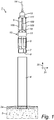
- a device 1 for drilling a shaft 2 in a ground layer 3.
- Ground layer 3 preferably comprises rock, but may also comprise clay and/or related materials.
- the ground layer 3 may be covered with a top layer 3a (also referred to as overburden), which generally comprises somewhat more loosely packed stone.
- Device 1 comprises a borehole casing 4 which can be arranged over at least part of its length in ground 3 by means of for instance pile-driving, oscillation or vibration. In the situation shown in figure 1 borehole casing 4 has been driven into overburden 3a.
- the diameter of borehole casing 4 can in principle be chosen within wide limits, but preferably amounts to at least 1 m, more preferably at least 2 m, still more preferably at least 4 m and most preferably at least 6 m. Because borehole casing 4 supports on its underside on a ground layer 3, a substantially water-impermeable sealing is achieved, though this may depend to some extent on the properties of ground layer 3 and is not therefore essential to the invention.
- borehole casing 4 comprises a thick-walled steel tube which is suitable for withstanding the forces exerted during insertion of borehole casing 4 into ground layer 3 and the drilling.
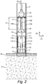
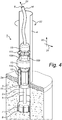
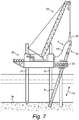
- Borehole casing 4 is sufficiently large to provide space for a drilling means 10, which can be lowered by means of a flexible suspension in the form of cable 26 (see figure 7 ) into borehole casing 4 to a position at a height of the underside of borehole casing 4.
- Drilling means 10 comprises a hollow drill string 5 which is provided on the side facing toward the ground 3 with a drill head 7 with cutting tools 8.
- Drill string 5 is received in a housing 9 (in figure 4 the housing is cut-away and therefore not visible), the peripheral surface of which is provided with securing means with which drilling means 10 can be secured in borehole casing 4.
- the securing means comprise four wedge-like peripheral parts (11, 12) distributed evenly over peripheral surface 9 and running in longitudinal direction 20 of borehole casing 4.
- Peripheral parts 11 are fixedly connected to the peripheral surface of housing 9 and have a thickness increasing in upward direction.
- Peripheral parts 12 are connected for translation in longitudinal direction 20 to the peripheral surface of housing 9 and have a thickness increasing in downward direction.
- jacks 110 connected to the fixed peripheral parts 11 (see figure 2 ) the movable peripheral parts 12 can be translated in longitudinal direction 20 relative to the fixed peripheral parts 11, this from a position as shown in figure 2 , in which they lie in a lowermost position, to a position as shown in figure 3 in which they lie in an uppermost position.
- the movable peripheral parts 12 co-act in their upper position with the fixed peripheral parts 11 such that a clamping force is created in radial direction 21 between drilling means 10 and the borehole casing 4.
- the developed clamping force substantially prevents a movement of drilling means 10 in longitudinal direction 20, radial direction 21 and peripheral direction 22.
- drill string 5 is provided in the shown embodiment with a weighting collar 15 which simultaneously serves as stop.
- the height position 17 of collar 15 relative to upper part 16 of drilling means 10 in the uppermost position of drill head 7 therefore defines the maximum stroke length of drill head 7.
- Drilling means 10 is further provided with means in the form of a rotary motor 13 for setting drill string 5 (and so also drill head 7) into rotation and translation, and with discharge means for dislodged ground material 21 in the form of a flexible hose 14 connected to the hollow drill string 5.
- the means for setting drill string 5 into translation in longitudinal direction 20 of borehole casing 4 comprise four jacks 109 which are slidable into each other and connect the upper part of the housing of rotary motor 13 to a web plate 111 of weighting collar 15.
- the hollow drill string 5 and the flexible hose together form a central cavity 6 through which dislodged ground material 21 can be discharged.
- the translating of drill string 5 by motor 13 takes place in longitudinal direction 20 of borehole casing 4 so that drill head 7 can hereby be moved out of or retracted into borehole casing 4.
- the means for setting drill string 5 into rotation and translation preferably comprise a transmission in the form of a swivel provided with motor 13.
- the transmission is designed such that it can transfer a fluid flow through cavity 6 from the stationary part (discharge hose 14) to the rotating part (drill shaft 5) of the device.
- the transmission is further suitable for transmitting the necessary torque from the stationary to the rotating part of the device and for discharging the water-ground material mixture 3.
- the transmission is further suitable for retaining these properties under the influence of the vibrations which inevitably occur during the drilling.
- borehole casing 4 and drill string 5 run substantially vertically in the shown figures, they can be adjusted to any angle to the vertical direction other than zero, for instance from a jack-up platform or pontoon (see figures 7 and 8 ) or from the shore when the device forms part of for instance a vehicle.
- device 1 is also provided with means (not shown) for maintaining a water column in borehole casing 4, for instance in the form of a pump with sufficient rise height and flow rate (typically for instance 1000 m 3 /h) so as to maintain the highest possible water level in borehole casing 4.
- the water column provides for a pressure difference between the upper side of flexible discharge hose 14 at the position of the water level and the underside of drill string 5 at the position of cutting tools 8, wherein the pressure is of course higher on the underside. Owing to this pressure difference and because borehole casing 5 is open on the underside, so that a throughfeed is possible to cavity 6, water and dislodged ground material 21 flow into cavity 6.
- a preferred variant also comprises means for injecting air under a second pressure into the hollow drill string 5 at the position of drill head 7.
- These means comprise feed lines which are arranged on drill string 5 and which are connected at the one outer end to a compressor and which debouch at the other outer end into cavity 6 of drill string 5 via air inlet valves.
- the compressor ensures that air is carried under a certain pressure through the lines and enters the upward flow in cavity 6. Because the compressed air has a lower density than the water flowing in cavity 6, the air rises as bubbles in drill string 5, whereby the upward flow is supported. The drilling efficiency is hereby increased.
- Drill head 7 of device 1 according to the invention can further be provided with nozzles directed outward in radial direction 21 for injecting a first fluid, preferably water, under a first pressure into ground layers 3 at the position of drill head 7.
- the device is provided for this purpose with feed lines (not shown) for feeding the first fluid to the nozzles.
- the lines are connected to pressure means such as a pump or compressor for bringing the first fluid under pressure.
- the nozzles are preferably mounted on drill head 7 so that they co-rotate with the drill head, although mounting on for instance the peripheral surface of housing 9 of drilling means 10 is likewise possible.
- Nozzles 25 are preferably suitable for injecting the water under a first pressure of at least 200 bar, more preferably at least 350 bar, still more preferably at least 500 bar and most preferably at least 650 bar. Because the nozzles are directed substantially radially outward, the water jets are injected into ground layer 3 at a greater depth than the lower outer end of borehole casing 4. Extra ground material is hereby removed or at least weakened at the position of the underside of borehole casing 4, whereby borehole casing 4 can move deeper into the ground 3.
- the feed lines for the first and second fluid can be long, particularly in the case of drilling at great depth. These lines are preferably carried substantially without bends from the upper side of device 1 to the lower part of drill string 5 and/or drill head 7. Pressure losses are hereby prevented as far as possible.
- a lifting platform 30 is shown which is provided with a device 1 according to the invention.
- a device 1 is particularly suitable for arranging pile foundations, on which jackets and/or monopiles for wind turbines can be placed, in underwater bottoms.
- the shown lifting platform 30 is anchored in the underwater bottom by means of spud piles 31 and can be further provided with a crane 32 and, if desired, other auxiliary means.
- Lifting platform 30 further comprises an outrigger 33.
- Outrigger 33 is provided with means for arranging borehole casing 4 in ground 3, which means comprise in the shown embodiment an oscillator 34 which, if desired, is adapted to arrange borehole casing 4 in the ground at an angle 35 to the vertical direction 40 other than zero, as shown in figure 8 .
- Frame 33 also allows positioning of borehole casing 4 within the required tolerance.
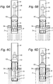
- a number of steps are shown of an embodiment of the method according to the invention.
- the jacks (109, 110) are not shown in the figures for the sake of clarity.
- a borehole casing 4 is first driven into ground 3 to a first depth, which corresponds for instance to the depth of overburden 3a (see figure 5A ).
- the borehole casing preferably admits substantially no water on its underside.
- the depth to which borehole casing 4 can be carried into ground 3 typically depends on the chosen arranging technique and on the properties of the ground at this depth.
- ground 3 is preferably a hard layer such as rock, limestone, hard clay or highly compacted sand.
- Overburden 3a usually comprises more easily penetrable soil such as for instance weathered rock, clay, peat, loosely compacted sand.
- drilling means 10 suspended from a flexible cable 26 is then lowered by means of crane 32 into borehole casing 4 from the position shown in figure 1 to a position as shown in figure 5A , in which the underside of drill head 7 lies at the level of the underside of borehole casing 4. In order to reach this level it may be necessary to have drill head 7 rotate in order to crush a ground material plug formed in borehole casing 4 and discharge it via the hollow drill shaft 5 and discharge line 14.
- drilling means 10 is secured in borehole casing 4 by relative translation of the peripheral parts 11, 12, as already described above.
- Drill string 5 is then set into rotation in borehole casing 4 with rotary motor 13 so that ground material 3 is dislodged by the cutting action of cutting tools 8, wherein drill head 7 moves in the longitudinal direction 20 of borehole casing 4 into ground 3 to a depth at which collar 15 makes contact with upper part 16 of drilling means 10 ( figure 5B ).
- the loosened ground material 3 is discharged during drilling via the flexible discharge hose 14 connected to the hollow drill string 5, if desired using a water column arranged in borehole casing 4 and by introducing air into discharge cavity 6, this as described in more detail above.
- Drill head 7 is subsequently retracted by rotary motor 13 to a position in which the underside of drill head 7 lies slightly above the level of the underside of borehole casing 4 ( figure 5C ), for instance over a distance roughly equal to the thickness of overburden 3a. At this moment a shaft 2 has been created with a depth corresponding to the stroke length 17 of collar 15.
- borehole casing 4 is then moved to a second depth greater than the first depth as shown in figure 6A using oscillator 34 on platform 30 or using another suitable pile-driving means. Lowering of borehole casing 4 into ground 3 is facilitated here by the presence of shaft 2. As shown in figures 6B and 6C , drill head 7 is then moved deeper into borehole casing 4 and drill string 5 is rotated so that further ground material 3 is dislodged by the cutting action of cutting tools 8 and discharged via the discharge hose 14 connected to the hollow drill string 5.
- drilling means 10 In order to reach the desired depth it may be necessary to uncouple drilling means 10 from borehole casing 4 by deactivating the securing means 11, 12, lowering drilling means 10 into borehole casing 4 to the desired height, and subsequently securing drilling means 10 once again by activating the securing means 11, 12 as described in more detail above.
- Drill head 7 is then once again retracted into borehole casing 4 by rotary motor 13 to a position in which the underside of drill head 7 lies slightly above the level of the underside of borehole casing 4, after which borehole casing 4 is driven together with drill head 7 further into the ground to a greater depth as shown in figure 6D .
- the above described sequence can then be repeated any number of times until the desired depth of shaft 2 has been reached.
- drilling means 10 is released from borehole casing 4 by deactivating the securing means, and the drilling means is raised by means of crane 32.
- the invented device and method are particularly suitable for drilling shafts of relatively large diameters in composite grounds so as to enable forming and/or arranging of foundation piles therein, wherein any desired depth can be reached without the drilling having to be interrupted at any time for assembly purposes.
Landscapes
- Engineering & Computer Science (AREA)
- Life Sciences & Earth Sciences (AREA)
- Geology (AREA)
- Mining & Mineral Resources (AREA)
- Physics & Mathematics (AREA)
- Environmental & Geological Engineering (AREA)
- Fluid Mechanics (AREA)
- General Life Sciences & Earth Sciences (AREA)
- Geochemistry & Mineralogy (AREA)
- Mechanical Engineering (AREA)
- Earth Drilling (AREA)
Priority Applications (1)
| Application Number | Priority Date | Filing Date | Title |
|---|---|---|---|
| PL13150026T PL2615239T3 (pl) | 2012-01-02 | 2013-01-02 | Urządzenie i sposób wiercenia szybów w gruncie składającym się ze skały, gliny i/albo podobnych materiałów |
Applications Claiming Priority (1)
| Application Number | Priority Date | Filing Date | Title |
|---|---|---|---|
| BE2012/0003A BE1020365A4 (nl) | 2012-01-02 | 2012-01-02 | Inrichting en werkwijze voor het boren van schachten in een uit rots, klei en/of aanverwante materialen bestaande ondergrond. |
Publications (2)
| Publication Number | Publication Date |
|---|---|
| EP2615239A1 EP2615239A1 (en) | 2013-07-17 |
| EP2615239B1 true EP2615239B1 (en) | 2019-10-30 |
Family
ID=47424883
Family Applications (1)
| Application Number | Title | Priority Date | Filing Date |
|---|---|---|---|
| EP13150026.6A Active EP2615239B1 (en) | 2012-01-02 | 2013-01-02 | Device and method for drilling shafts in a ground consisting of rock, clay and/or related materials |
Country Status (4)
| Country | Link |
|---|---|
| EP (1) | EP2615239B1 (pl) |
| BE (1) | BE1020365A4 (pl) |
| DK (1) | DK2615239T3 (pl) |
| PL (1) | PL2615239T3 (pl) |
Cited By (3)
| Publication number | Priority date | Publication date | Assignee | Title |
|---|---|---|---|---|
| EP3862528A1 (de) | 2020-02-04 | 2021-08-11 | BAUER Maschinen GmbH | Imloch-bohrgerät und verfahren zum erstellen einer bohrung |
| EP4286593A1 (de) | 2022-05-30 | 2023-12-06 | BAUER Spezialtiefbau GmbH | Tiefbaugerät und verfahren zum erstellen eines loches |
| EP4350119A1 (de) | 2022-10-06 | 2024-04-10 | BAUER Maschinen GmbH | Unterwasser-bohrvorrichtung und verfahren zum erstellen einer verrohrung unter wasser |
Families Citing this family (4)
| Publication number | Priority date | Publication date | Assignee | Title |
|---|---|---|---|---|
| BE1022222B1 (nl) * | 2014-10-31 | 2016-03-02 | D.E.C.O. Nv | Ruiminrichting en werkwijze voor het ruimen van vulmateriaal in offshore structuren |
| DE102015105908B4 (de) | 2015-04-17 | 2024-08-01 | Bauer Maschinen Gmbh | Bohrgerät zum Erstellen einer verrohrten Bohrung und Verfahren zum Betreiben eines Bohrgerätes |
| JP6770733B2 (ja) * | 2016-06-24 | 2020-10-21 | 三和機材株式会社 | 掘削装置 |
| CN109736699B (zh) * | 2019-03-10 | 2024-06-28 | 东营华来智能科技有限公司 | 一种钻井增速动力夯机 |
Citations (12)
| Publication number | Priority date | Publication date | Assignee | Title |
|---|---|---|---|---|
| US3001592A (en) | 1954-09-03 | 1961-09-26 | De Long Corp | Well drilling and servicing barge including bridge and rig structure and methods |
| GB938191A (en) | 1960-06-09 | 1963-10-02 | Bade & Co Gmbh | Method and equipment for sinking a pipe casing |
| US3860122A (en) | 1972-12-07 | 1975-01-14 | Louis C Cernosek | Positioning apparatus |
| GB1506388A (en) | 1975-05-23 | 1978-04-05 | Lilley Waddington Ltd | Excavation of bore holes |
| DE2734185A1 (de) | 1977-07-29 | 1979-02-08 | Leffer Stahl & App | Verfahren und anlage zum niederbringen einer verrohrten tiefbohrung zur herstellung von verrohrten pfahlgruendungen |
| DE3741717A1 (de) * | 1987-12-09 | 1989-06-29 | Wirth Co Kg Masch Bohr | Vorrichtung zum niederbringen von im wesentlichen vertikalen bohrungen |
| DE4308856C1 (de) | 1993-03-19 | 1994-05-26 | Leffer Stahl & App | Verfahren und Bohrgerät zur Herstellung einer verrohrten Tiefbohrung, insbesondere für Pfahlgründungen |
| JPH0941859A (ja) | 1995-07-26 | 1997-02-10 | Nippon Sharyo Seizo Kaisha Ltd | 硬岩層掘削方法及びその装置 |
| JP2002276273A (ja) | 2001-03-16 | 2002-09-25 | Kencho Co Ltd | 掘削用回転駆動装置 |
| DE10336315A1 (de) | 2003-08-07 | 2005-03-03 | Helmut Hross | Vertikalbohrvorrichtung sowie Verfahren zur Erstellung im wesentlichen vertikal ausgerichteter Grossbohrungen in Grundformationen |
| WO2010106124A2 (en) | 2009-03-19 | 2010-09-23 | Geosea Nv | Method and device for drilling shafts in ground layers consisting of rock, clay and/or related materials |
| WO2010123375A1 (en) | 2009-04-22 | 2010-10-28 | Aker Well Service As | Stroker device |
Family Cites Families (2)
| Publication number | Priority date | Publication date | Assignee | Title |
|---|---|---|---|---|
| FR2832454B1 (fr) * | 2001-11-20 | 2004-07-09 | Cie Du Sol | Equipement de forage de puits verticaux |
| CN101297095A (zh) * | 2005-10-27 | 2008-10-29 | 国际壳牌研究有限公司 | 大位移井钻井设备和方法 |
-
2012
- 2012-01-02 BE BE2012/0003A patent/BE1020365A4/nl not_active IP Right Cessation
-
2013
- 2013-01-02 DK DK13150026.6T patent/DK2615239T3/da active
- 2013-01-02 EP EP13150026.6A patent/EP2615239B1/en active Active
- 2013-01-02 PL PL13150026T patent/PL2615239T3/pl unknown
Patent Citations (13)
| Publication number | Priority date | Publication date | Assignee | Title |
|---|---|---|---|---|
| US3001592A (en) | 1954-09-03 | 1961-09-26 | De Long Corp | Well drilling and servicing barge including bridge and rig structure and methods |
| GB938191A (en) | 1960-06-09 | 1963-10-02 | Bade & Co Gmbh | Method and equipment for sinking a pipe casing |
| US3860122A (en) | 1972-12-07 | 1975-01-14 | Louis C Cernosek | Positioning apparatus |
| GB1506388A (en) | 1975-05-23 | 1978-04-05 | Lilley Waddington Ltd | Excavation of bore holes |
| DE2734185A1 (de) | 1977-07-29 | 1979-02-08 | Leffer Stahl & App | Verfahren und anlage zum niederbringen einer verrohrten tiefbohrung zur herstellung von verrohrten pfahlgruendungen |
| GB2002047A (en) | 1977-07-29 | 1979-02-14 | Leffer Stahl & App | Sinking a cased borehole |
| DE3741717A1 (de) * | 1987-12-09 | 1989-06-29 | Wirth Co Kg Masch Bohr | Vorrichtung zum niederbringen von im wesentlichen vertikalen bohrungen |
| DE4308856C1 (de) | 1993-03-19 | 1994-05-26 | Leffer Stahl & App | Verfahren und Bohrgerät zur Herstellung einer verrohrten Tiefbohrung, insbesondere für Pfahlgründungen |
| JPH0941859A (ja) | 1995-07-26 | 1997-02-10 | Nippon Sharyo Seizo Kaisha Ltd | 硬岩層掘削方法及びその装置 |
| JP2002276273A (ja) | 2001-03-16 | 2002-09-25 | Kencho Co Ltd | 掘削用回転駆動装置 |
| DE10336315A1 (de) | 2003-08-07 | 2005-03-03 | Helmut Hross | Vertikalbohrvorrichtung sowie Verfahren zur Erstellung im wesentlichen vertikal ausgerichteter Grossbohrungen in Grundformationen |
| WO2010106124A2 (en) | 2009-03-19 | 2010-09-23 | Geosea Nv | Method and device for drilling shafts in ground layers consisting of rock, clay and/or related materials |
| WO2010123375A1 (en) | 2009-04-22 | 2010-10-28 | Aker Well Service As | Stroker device |
Non-Patent Citations (2)
| Title |
|---|
| ANONYM: "DEUTSCHE NORM DIN EN 1536: Bohrpfähle. Deutsche Fassung EN 1536: 1999", DEUTSCHE NORM DIN, 1 June 1999 (1999-06-01), pages 1 - 22, XP055778365 |
| SMOLTCZYK: "Grundbau-Taschenbuch, Teil 2: Geotechnische Verfahren. Sechste Auflage", ERNST & SOHN, 1 January 2001 (2001-01-01), pages 233 - 235, XP055778360 |
Cited By (6)
| Publication number | Priority date | Publication date | Assignee | Title |
|---|---|---|---|---|
| EP3862528A1 (de) | 2020-02-04 | 2021-08-11 | BAUER Maschinen GmbH | Imloch-bohrgerät und verfahren zum erstellen einer bohrung |
| WO2021156049A1 (de) | 2020-02-04 | 2021-08-12 | Bauer Maschinen Gmbh | Imloch-bohrgerät und verfahren zum erstellen einer bohrung |
| EP4286593A1 (de) | 2022-05-30 | 2023-12-06 | BAUER Spezialtiefbau GmbH | Tiefbaugerät und verfahren zum erstellen eines loches |
| WO2023232393A1 (de) | 2022-05-30 | 2023-12-07 | Bauer Spezialtiefbau Gmbh | Tiefbaugerät und verfahren zum erstellen eines loches |
| EP4350119A1 (de) | 2022-10-06 | 2024-04-10 | BAUER Maschinen GmbH | Unterwasser-bohrvorrichtung und verfahren zum erstellen einer verrohrung unter wasser |
| US12146408B2 (en) | 2022-10-06 | 2024-11-19 | Bauer Maschinen Gmbh | Underwater drilling apparatus and method for creating a cased borehole underwater |
Also Published As
| Publication number | Publication date |
|---|---|
| DK2615239T3 (da) | 2020-02-10 |
| EP2615239A1 (en) | 2013-07-17 |
| BE1020365A4 (nl) | 2013-08-06 |
| PL2615239T3 (pl) | 2020-06-29 |
Similar Documents
| Publication | Publication Date | Title |
|---|---|---|
| EP2615239B1 (en) | Device and method for drilling shafts in a ground consisting of rock, clay and/or related materials | |
| EP2408992B1 (en) | Method and device for drilling shafts in ground layers consisting of rock, clay and/or related materials | |
| CN102803616B (zh) | 用于制造建筑物的水下基础的方法和设备 | |
| US8757289B2 (en) | Underwater drilling arrangement and method for making a bore in a bed of a water body | |
| US2589146A (en) | Submersible deepwater drilling apparatus | |
| JP2002529630A (ja) | 沖合水中工事用ケーソン | |
| CA2285349C (en) | Position penetrated anchor system | |
| US4815894A (en) | Construction and use of subsea bore holes | |
| US11952736B2 (en) | System and method for installing an aggregate pier | |
| US4579481A (en) | Mobile offshore drilling structure for the arctic | |
| CN114277797B (zh) | 一种钢管桩沉桩装置 | |
| CA2865399A1 (en) | Method and apparatus for volume reduction of fine particulate | |
| EP3252263B1 (en) | Device and method for drilling a large diameter borehole | |
| EP3260650B1 (en) | Device and method for drilling a shaft in a substrate | |
| CN109339044A (zh) | 一种混凝土管桩施工设备 | |
| US3824794A (en) | Offshore marine anchoring structure | |
| CN209989811U (zh) | 一种流砂段预制钢护筒预成孔深层水下夯实施工装置 | |
| CN114370230A (zh) | 岩层中垂直顶升取排水管预处理方法 | |
| KR102511528B1 (ko) | 기초 구조물의 제조 방법 및 제조 장치 및 기초 구조물 | |
| CN215253065U (zh) | 一种海上深水风电场斜桩加固基础 | |
| KR102950542B1 (ko) | 암반 굴착용 가이드 케이싱 및 이를 이용한 풍력단지 시공 방법 | |
| EP4522809A1 (en) | Method of installation of a drill pile and the drill pill | |
| Spagnoli et al. | Alternative offshore foundation installation methods | |
| KR20230133964A (ko) | 해양 구조물을 위한 기초 및 기초를 설치하기 위한방법 | |
| CN116927654A (zh) | 一种复杂地质主塔桩基干作业成孔施工方法及辅助装置 |
Legal Events
| Date | Code | Title | Description |
|---|---|---|---|
| PUAI | Public reference made under article 153(3) epc to a published international application that has entered the european phase |
Free format text: ORIGINAL CODE: 0009012 |
|
| AK | Designated contracting states |
Kind code of ref document: A1 Designated state(s): AL AT BE BG CH CY CZ DE DK EE ES FI FR GB GR HR HU IE IS IT LI LT LU LV MC MK MT NL NO PL PT RO RS SE SI SK SM TR |
|
| AX | Request for extension of the european patent |
Extension state: BA ME |
|
| 17P | Request for examination filed |
Effective date: 20140117 |
|
| RBV | Designated contracting states (corrected) |
Designated state(s): AL AT BE BG CH CY CZ DE DK EE ES FI FR GB GR HR HU IE IS IT LI LT LU LV MC MK MT NL NO PL PT RO RS SE SI SK SM TR |
|
| 17Q | First examination report despatched |
Effective date: 20140926 |
|
| TPAC | Observations filed by third parties |
Free format text: ORIGINAL CODE: EPIDOSNTIPA |
|
| TPAC | Observations filed by third parties |
Free format text: ORIGINAL CODE: EPIDOSNTIPA |
|
| STAA | Information on the status of an ep patent application or granted ep patent |
Free format text: STATUS: EXAMINATION IS IN PROGRESS |
|
| TPAC | Observations filed by third parties |
Free format text: ORIGINAL CODE: EPIDOSNTIPA |
|
| GRAP | Despatch of communication of intention to grant a patent |
Free format text: ORIGINAL CODE: EPIDOSNIGR1 |
|
| STAA | Information on the status of an ep patent application or granted ep patent |
Free format text: STATUS: GRANT OF PATENT IS INTENDED |
|
| INTG | Intention to grant announced |
Effective date: 20190514 |
|
| GRAS | Grant fee paid |
Free format text: ORIGINAL CODE: EPIDOSNIGR3 |
|
| GRAA | (expected) grant |
Free format text: ORIGINAL CODE: 0009210 |
|
| STAA | Information on the status of an ep patent application or granted ep patent |
Free format text: STATUS: THE PATENT HAS BEEN GRANTED |
|
| AK | Designated contracting states |
Kind code of ref document: B1 Designated state(s): AL AT BE BG CH CY CZ DE DK EE ES FI FR GB GR HR HU IE IS IT LI LT LU LV MC MK MT NL NO PL PT RO RS SE SI SK SM TR |
|
| REG | Reference to a national code |
Ref country code: GB Ref legal event code: FG4D |
|
| REG | Reference to a national code |
Ref country code: CH Ref legal event code: EP |
|
| REG | Reference to a national code |
Ref country code: AT Ref legal event code: REF Ref document number: 1196318 Country of ref document: AT Kind code of ref document: T Effective date: 20191115 |
|
| REG | Reference to a national code |
Ref country code: DE Ref legal event code: R096 Ref document number: 602013062178 Country of ref document: DE |
|
| REG | Reference to a national code |
Ref country code: IE Ref legal event code: FG4D |
|
| REG | Reference to a national code |
Ref country code: DK Ref legal event code: T3 Effective date: 20200207 |
|
| REG | Reference to a national code |
Ref country code: SE Ref legal event code: TRGR |
|
| RAP2 | Party data changed (patent owner data changed or rights of a patent transferred) |
Owner name: DEME OFFSHORE BE N.V. |
|
| REG | Reference to a national code |
Ref country code: GB Ref legal event code: 732E Free format text: REGISTERED BETWEEN 20200130 AND 20200205 |
|
| REG | Reference to a national code |
Ref country code: LT Ref legal event code: MG4D |
|
| REG | Reference to a national code |
Ref country code: DE Ref legal event code: R081 Ref document number: 602013062178 Country of ref document: DE Owner name: DEME OFFSHORE BE NV, BE Free format text: FORMER OWNER: GEOSEA NV, ZWIJNDRECHT, BE |
|
| REG | Reference to a national code |
Ref country code: NL Ref legal event code: FP Ref country code: NL Ref legal event code: PD Owner name: DEME OFFSHORE BE N.V.; BE Free format text: DETAILS ASSIGNMENT: CHANGE OF OWNER(S), ASSIGNMENT; FORMER OWNER NAME: GEOSEA NV Effective date: 20200305 |
|
| REG | Reference to a national code |
Ref country code: BE Ref legal event code: PD Owner name: DEME OFFSHORE BE N.V.; BE Free format text: DETAILS ASSIGNMENT: CHANGE OF OWNER(S), CESSION, OEB; FORMER OWNER NAME: GEOSEA NV Effective date: 20200128 |
|
| PG25 | Lapsed in a contracting state [announced via postgrant information from national office to epo] |
Ref country code: BG Free format text: LAPSE BECAUSE OF FAILURE TO SUBMIT A TRANSLATION OF THE DESCRIPTION OR TO PAY THE FEE WITHIN THE PRESCRIBED TIME-LIMIT Effective date: 20200130 Ref country code: FI Free format text: LAPSE BECAUSE OF FAILURE TO SUBMIT A TRANSLATION OF THE DESCRIPTION OR TO PAY THE FEE WITHIN THE PRESCRIBED TIME-LIMIT Effective date: 20191030 Ref country code: GR Free format text: LAPSE BECAUSE OF FAILURE TO SUBMIT A TRANSLATION OF THE DESCRIPTION OR TO PAY THE FEE WITHIN THE PRESCRIBED TIME-LIMIT Effective date: 20200131 Ref country code: NO Free format text: LAPSE BECAUSE OF FAILURE TO SUBMIT A TRANSLATION OF THE DESCRIPTION OR TO PAY THE FEE WITHIN THE PRESCRIBED TIME-LIMIT Effective date: 20200130 Ref country code: LV Free format text: LAPSE BECAUSE OF FAILURE TO SUBMIT A TRANSLATION OF THE DESCRIPTION OR TO PAY THE FEE WITHIN THE PRESCRIBED TIME-LIMIT Effective date: 20191030 Ref country code: ES Free format text: LAPSE BECAUSE OF FAILURE TO SUBMIT A TRANSLATION OF THE DESCRIPTION OR TO PAY THE FEE WITHIN THE PRESCRIBED TIME-LIMIT Effective date: 20191030 Ref country code: PT Free format text: LAPSE BECAUSE OF FAILURE TO SUBMIT A TRANSLATION OF THE DESCRIPTION OR TO PAY THE FEE WITHIN THE PRESCRIBED TIME-LIMIT Effective date: 20200302 Ref country code: LT Free format text: LAPSE BECAUSE OF FAILURE TO SUBMIT A TRANSLATION OF THE DESCRIPTION OR TO PAY THE FEE WITHIN THE PRESCRIBED TIME-LIMIT Effective date: 20191030 |
|
| PG25 | Lapsed in a contracting state [announced via postgrant information from national office to epo] |
Ref country code: HR Free format text: LAPSE BECAUSE OF FAILURE TO SUBMIT A TRANSLATION OF THE DESCRIPTION OR TO PAY THE FEE WITHIN THE PRESCRIBED TIME-LIMIT Effective date: 20191030 Ref country code: RS Free format text: LAPSE BECAUSE OF FAILURE TO SUBMIT A TRANSLATION OF THE DESCRIPTION OR TO PAY THE FEE WITHIN THE PRESCRIBED TIME-LIMIT Effective date: 20191030 Ref country code: IS Free format text: LAPSE BECAUSE OF FAILURE TO SUBMIT A TRANSLATION OF THE DESCRIPTION OR TO PAY THE FEE WITHIN THE PRESCRIBED TIME-LIMIT Effective date: 20200229 |
|
| PG25 | Lapsed in a contracting state [announced via postgrant information from national office to epo] |
Ref country code: AL Free format text: LAPSE BECAUSE OF FAILURE TO SUBMIT A TRANSLATION OF THE DESCRIPTION OR TO PAY THE FEE WITHIN THE PRESCRIBED TIME-LIMIT Effective date: 20191030 |
|
| REG | Reference to a national code |
Ref country code: DE Ref legal event code: R026 Ref document number: 602013062178 Country of ref document: DE |
|
| PG25 | Lapsed in a contracting state [announced via postgrant information from national office to epo] |
Ref country code: CZ Free format text: LAPSE BECAUSE OF FAILURE TO SUBMIT A TRANSLATION OF THE DESCRIPTION OR TO PAY THE FEE WITHIN THE PRESCRIBED TIME-LIMIT Effective date: 20191030 Ref country code: EE Free format text: LAPSE BECAUSE OF FAILURE TO SUBMIT A TRANSLATION OF THE DESCRIPTION OR TO PAY THE FEE WITHIN THE PRESCRIBED TIME-LIMIT Effective date: 20191030 Ref country code: RO Free format text: LAPSE BECAUSE OF FAILURE TO SUBMIT A TRANSLATION OF THE DESCRIPTION OR TO PAY THE FEE WITHIN THE PRESCRIBED TIME-LIMIT Effective date: 20191030 |
|
| PLBI | Opposition filed |
Free format text: ORIGINAL CODE: 0009260 |
|
| REG | Reference to a national code |
Ref country code: AT Ref legal event code: MK05 Ref document number: 1196318 Country of ref document: AT Kind code of ref document: T Effective date: 20191030 |
|
| PG25 | Lapsed in a contracting state [announced via postgrant information from national office to epo] |
Ref country code: MC Free format text: LAPSE BECAUSE OF FAILURE TO SUBMIT A TRANSLATION OF THE DESCRIPTION OR TO PAY THE FEE WITHIN THE PRESCRIBED TIME-LIMIT Effective date: 20191030 Ref country code: SM Free format text: LAPSE BECAUSE OF FAILURE TO SUBMIT A TRANSLATION OF THE DESCRIPTION OR TO PAY THE FEE WITHIN THE PRESCRIBED TIME-LIMIT Effective date: 20191030 Ref country code: IT Free format text: LAPSE BECAUSE OF FAILURE TO SUBMIT A TRANSLATION OF THE DESCRIPTION OR TO PAY THE FEE WITHIN THE PRESCRIBED TIME-LIMIT Effective date: 20191030 Ref country code: SK Free format text: LAPSE BECAUSE OF FAILURE TO SUBMIT A TRANSLATION OF THE DESCRIPTION OR TO PAY THE FEE WITHIN THE PRESCRIBED TIME-LIMIT Effective date: 20191030 |
|
| REG | Reference to a national code |
Ref country code: CH Ref legal event code: PL |
|
| PLAX | Notice of opposition and request to file observation + time limit sent |
Free format text: ORIGINAL CODE: EPIDOSNOBS2 |
|
| 26 | Opposition filed |
Opponent name: BAUER MASCHINEN GMBH Effective date: 20200730 |
|
| PLAF | Information modified related to communication of a notice of opposition and request to file observations + time limit |
Free format text: ORIGINAL CODE: EPIDOSCOBS2 |
|
| PG25 | Lapsed in a contracting state [announced via postgrant information from national office to epo] |
Ref country code: LU Free format text: LAPSE BECAUSE OF NON-PAYMENT OF DUE FEES Effective date: 20200102 |
|
| PG25 | Lapsed in a contracting state [announced via postgrant information from national office to epo] |
Ref country code: LI Free format text: LAPSE BECAUSE OF NON-PAYMENT OF DUE FEES Effective date: 20200131 Ref country code: CH Free format text: LAPSE BECAUSE OF NON-PAYMENT OF DUE FEES Effective date: 20200131 Ref country code: AT Free format text: LAPSE BECAUSE OF FAILURE TO SUBMIT A TRANSLATION OF THE DESCRIPTION OR TO PAY THE FEE WITHIN THE PRESCRIBED TIME-LIMIT Effective date: 20191030 Ref country code: SI Free format text: LAPSE BECAUSE OF FAILURE TO SUBMIT A TRANSLATION OF THE DESCRIPTION OR TO PAY THE FEE WITHIN THE PRESCRIBED TIME-LIMIT Effective date: 20191030 |
|
| PLBB | Reply of patent proprietor to notice(s) of opposition received |
Free format text: ORIGINAL CODE: EPIDOSNOBS3 |
|
| PG25 | Lapsed in a contracting state [announced via postgrant information from national office to epo] |
Ref country code: TR Free format text: LAPSE BECAUSE OF FAILURE TO SUBMIT A TRANSLATION OF THE DESCRIPTION OR TO PAY THE FEE WITHIN THE PRESCRIBED TIME-LIMIT Effective date: 20191030 Ref country code: MT Free format text: LAPSE BECAUSE OF FAILURE TO SUBMIT A TRANSLATION OF THE DESCRIPTION OR TO PAY THE FEE WITHIN THE PRESCRIBED TIME-LIMIT Effective date: 20191030 Ref country code: CY Free format text: LAPSE BECAUSE OF FAILURE TO SUBMIT A TRANSLATION OF THE DESCRIPTION OR TO PAY THE FEE WITHIN THE PRESCRIBED TIME-LIMIT Effective date: 20191030 |
|
| PG25 | Lapsed in a contracting state [announced via postgrant information from national office to epo] |
Ref country code: MK Free format text: LAPSE BECAUSE OF FAILURE TO SUBMIT A TRANSLATION OF THE DESCRIPTION OR TO PAY THE FEE WITHIN THE PRESCRIBED TIME-LIMIT Effective date: 20191030 |
|
| PLCK | Communication despatched that opposition was rejected |
Free format text: ORIGINAL CODE: EPIDOSNREJ1 |
|
| APAH | Appeal reference modified |
Free format text: ORIGINAL CODE: EPIDOSCREFNO |
|
| APBM | Appeal reference recorded |
Free format text: ORIGINAL CODE: EPIDOSNREFNO |
|
| APBP | Date of receipt of notice of appeal recorded |
Free format text: ORIGINAL CODE: EPIDOSNNOA2O |
|
| PLCK | Communication despatched that opposition was rejected |
Free format text: ORIGINAL CODE: EPIDOSNREJ1 |
|
| APBQ | Date of receipt of statement of grounds of appeal recorded |
Free format text: ORIGINAL CODE: EPIDOSNNOA3O |
|
| P01 | Opt-out of the competence of the unified patent court (upc) registered |
Effective date: 20230526 |
|
| RAP4 | Party data changed (patent owner data changed or rights of a patent transferred) |
Owner name: DEME OFFSHORE BE NV |
|
| REG | Reference to a national code |
Ref country code: DE Ref legal event code: R100 Ref document number: 602013062178 Country of ref document: DE |
|
| APBU | Appeal procedure closed |
Free format text: ORIGINAL CODE: EPIDOSNNOA9O |
|
| PLBN | Opposition rejected |
Free format text: ORIGINAL CODE: 0009273 |
|
| STAA | Information on the status of an ep patent application or granted ep patent |
Free format text: STATUS: OPPOSITION REJECTED |
|
| 27O | Opposition rejected |
Effective date: 20250203 |
|
| PGFP | Annual fee paid to national office [announced via postgrant information from national office to epo] |
Ref country code: DK Payment date: 20251223 Year of fee payment: 14 |
|
| PGFP | Annual fee paid to national office [announced via postgrant information from national office to epo] |
Ref country code: PL Payment date: 20251204 Year of fee payment: 14 |
|
| PGFP | Annual fee paid to national office [announced via postgrant information from national office to epo] |
Ref country code: NL Payment date: 20260108 Year of fee payment: 14 |
|
| PGFP | Annual fee paid to national office [announced via postgrant information from national office to epo] |
Ref country code: SE Payment date: 20260107 Year of fee payment: 14 |
|
| PGFP | Annual fee paid to national office [announced via postgrant information from national office to epo] |
Ref country code: GB Payment date: 20260113 Year of fee payment: 14 |
|
| PGFP | Annual fee paid to national office [announced via postgrant information from national office to epo] |
Ref country code: IE Payment date: 20260108 Year of fee payment: 14 Ref country code: DE Payment date: 20260108 Year of fee payment: 14 |
|
| PGFP | Annual fee paid to national office [announced via postgrant information from national office to epo] |
Ref country code: BE Payment date: 20260108 Year of fee payment: 14 |
|
| PGFP | Annual fee paid to national office [announced via postgrant information from national office to epo] |
Ref country code: FR Payment date: 20260113 Year of fee payment: 14 |