EP2614907B1 - Insert de découpe avec surface de support en biais, porte-outil avec surface de butée en biais et outil de découpe - Google Patents
Insert de découpe avec surface de support en biais, porte-outil avec surface de butée en biais et outil de découpe Download PDFInfo
- Publication number
- EP2614907B1 EP2614907B1 EP12151084.6A EP12151084A EP2614907B1 EP 2614907 B1 EP2614907 B1 EP 2614907B1 EP 12151084 A EP12151084 A EP 12151084A EP 2614907 B1 EP2614907 B1 EP 2614907B1
- Authority
- EP
- European Patent Office
- Prior art keywords
- angle
- cutting
- angled
- insert
- supporting
- Prior art date
- Legal status (The legal status is an assumption and is not a legal conclusion. Google has not performed a legal analysis and makes no representation as to the accuracy of the status listed.)
- Active
Links
- 230000007935 neutral effect Effects 0.000 claims description 10
- 230000001154 acute effect Effects 0.000 claims description 5
- 239000000463 material Substances 0.000 description 5
- 238000010008 shearing Methods 0.000 description 2
- ATJFFYVFTNAWJD-UHFFFAOYSA-N Tin Chemical compound [Sn] ATJFFYVFTNAWJD-UHFFFAOYSA-N 0.000 description 1
- PNEYBMLMFCGWSK-UHFFFAOYSA-N aluminium oxide Inorganic materials [O-2].[O-2].[O-2].[Al+3].[Al+3] PNEYBMLMFCGWSK-UHFFFAOYSA-N 0.000 description 1
- 239000011230 binding agent Substances 0.000 description 1
- 229910052593 corundum Inorganic materials 0.000 description 1
- 230000002452 interceptive effect Effects 0.000 description 1
- 238000003754 machining Methods 0.000 description 1
- 230000013011 mating Effects 0.000 description 1
- 239000002184 metal Substances 0.000 description 1
- 239000007769 metal material Substances 0.000 description 1
- 238000003801 milling Methods 0.000 description 1
- 229910001845 yogo sapphire Inorganic materials 0.000 description 1
Images


Classifications
-
- B—PERFORMING OPERATIONS; TRANSPORTING
- B23—MACHINE TOOLS; METAL-WORKING NOT OTHERWISE PROVIDED FOR
- B23C—MILLING
- B23C5/00—Milling-cutters
- B23C5/16—Milling-cutters characterised by physical features other than shape
- B23C5/20—Milling-cutters characterised by physical features other than shape with removable cutter bits or teeth or cutting inserts
- B23C5/202—Plate-like cutting inserts with special form
-
- B—PERFORMING OPERATIONS; TRANSPORTING
- B23—MACHINE TOOLS; METAL-WORKING NOT OTHERWISE PROVIDED FOR
- B23B—TURNING; BORING
- B23B27/00—Tools for turning or boring machines; Tools of a similar kind in general; Accessories therefor
- B23B27/14—Cutting tools of which the bits or tips or cutting inserts are of special material
- B23B27/16—Cutting tools of which the bits or tips or cutting inserts are of special material with exchangeable cutting bits or cutting inserts, e.g. able to be clamped
- B23B27/1614—Cutting tools of which the bits or tips or cutting inserts are of special material with exchangeable cutting bits or cutting inserts, e.g. able to be clamped with plate-like cutting inserts of special shape clamped against the walls of the recess in the shank by a clamping member acting upon the wall of a hole in the insert
- B23B27/1622—Cutting tools of which the bits or tips or cutting inserts are of special material with exchangeable cutting bits or cutting inserts, e.g. able to be clamped with plate-like cutting inserts of special shape clamped against the walls of the recess in the shank by a clamping member acting upon the wall of a hole in the insert characterised by having a special shape
-
- B—PERFORMING OPERATIONS; TRANSPORTING
- B23—MACHINE TOOLS; METAL-WORKING NOT OTHERWISE PROVIDED FOR
- B23B—TURNING; BORING
- B23B27/00—Tools for turning or boring machines; Tools of a similar kind in general; Accessories therefor
- B23B27/14—Cutting tools of which the bits or tips or cutting inserts are of special material
- B23B27/16—Cutting tools of which the bits or tips or cutting inserts are of special material with exchangeable cutting bits or cutting inserts, e.g. able to be clamped
- B23B27/1603—Cutting tools of which the bits or tips or cutting inserts are of special material with exchangeable cutting bits or cutting inserts, e.g. able to be clamped with specially shaped plate-like exchangeable cutting inserts, e.g. chip-breaking groove
- B23B27/1611—Cutting tools of which the bits or tips or cutting inserts are of special material with exchangeable cutting bits or cutting inserts, e.g. able to be clamped with specially shaped plate-like exchangeable cutting inserts, e.g. chip-breaking groove characterised by having a special shape
-
- B—PERFORMING OPERATIONS; TRANSPORTING
- B23—MACHINE TOOLS; METAL-WORKING NOT OTHERWISE PROVIDED FOR
- B23C—MILLING
- B23C5/00—Milling-cutters
- B23C5/16—Milling-cutters characterised by physical features other than shape
- B23C5/20—Milling-cutters characterised by physical features other than shape with removable cutter bits or teeth or cutting inserts
- B23C5/22—Securing arrangements for bits or teeth or cutting inserts
- B23C5/2204—Securing arrangements for bits or teeth or cutting inserts with cutting inserts clamped against the walls of the recess in the cutter body by a clamping member acting upon the wall of a hole in the insert
- B23C5/2208—Securing arrangements for bits or teeth or cutting inserts with cutting inserts clamped against the walls of the recess in the cutter body by a clamping member acting upon the wall of a hole in the insert for plate-like cutting inserts
- B23C5/2213—Securing arrangements for bits or teeth or cutting inserts with cutting inserts clamped against the walls of the recess in the cutter body by a clamping member acting upon the wall of a hole in the insert for plate-like cutting inserts having a special shape
-
- B—PERFORMING OPERATIONS; TRANSPORTING
- B23—MACHINE TOOLS; METAL-WORKING NOT OTHERWISE PROVIDED FOR
- B23C—MILLING
- B23C2200/00—Details of milling cutting inserts
- B23C2200/08—Rake or top surfaces
- B23C2200/086—Rake or top surfaces with one or more grooves
-
- B—PERFORMING OPERATIONS; TRANSPORTING
- B23—MACHINE TOOLS; METAL-WORKING NOT OTHERWISE PROVIDED FOR
- B23C—MILLING
- B23C2200/00—Details of milling cutting inserts
- B23C2200/16—Supporting or bottom surfaces
- B23C2200/165—Supporting or bottom surfaces with one or more grooves
-
- B—PERFORMING OPERATIONS; TRANSPORTING
- B23—MACHINE TOOLS; METAL-WORKING NOT OTHERWISE PROVIDED FOR
- B23C—MILLING
- B23C2200/00—Details of milling cutting inserts
- B23C2200/28—Angles
-
- B—PERFORMING OPERATIONS; TRANSPORTING
- B23—MACHINE TOOLS; METAL-WORKING NOT OTHERWISE PROVIDED FOR
- B23C—MILLING
- B23C2200/00—Details of milling cutting inserts
- B23C2200/28—Angles
- B23C2200/284—Negative clearance angles
-
- B—PERFORMING OPERATIONS; TRANSPORTING
- B23—MACHINE TOOLS; METAL-WORKING NOT OTHERWISE PROVIDED FOR
- B23C—MILLING
- B23C2210/00—Details of milling cutters
- B23C2210/04—Angles
- B23C2210/0407—Cutting angles
-
- B—PERFORMING OPERATIONS; TRANSPORTING
- B23—MACHINE TOOLS; METAL-WORKING NOT OTHERWISE PROVIDED FOR
- B23C—MILLING
- B23C2210/00—Details of milling cutters
- B23C2210/16—Fixation of inserts or cutting bits in the tool
- B23C2210/168—Seats for cutting inserts, supports for replacable cutting bits
-
- B—PERFORMING OPERATIONS; TRANSPORTING
- B23—MACHINE TOOLS; METAL-WORKING NOT OTHERWISE PROVIDED FOR
- B23C—MILLING
- B23C2210/00—Details of milling cutters
- B23C2210/50—Cutting inserts
-
- Y—GENERAL TAGGING OF NEW TECHNOLOGICAL DEVELOPMENTS; GENERAL TAGGING OF CROSS-SECTIONAL TECHNOLOGIES SPANNING OVER SEVERAL SECTIONS OF THE IPC; TECHNICAL SUBJECTS COVERED BY FORMER USPC CROSS-REFERENCE ART COLLECTIONS [XRACs] AND DIGESTS
- Y10—TECHNICAL SUBJECTS COVERED BY FORMER USPC
- Y10T—TECHNICAL SUBJECTS COVERED BY FORMER US CLASSIFICATION
- Y10T407/00—Cutters, for shaping
- Y10T407/19—Rotary cutting tool
- Y10T407/1906—Rotary cutting tool including holder [i.e., head] having seat for inserted tool
- Y10T407/1934—Rotary cutting tool including holder [i.e., head] having seat for inserted tool with separate means to fasten tool to holder
- Y10T407/1936—Apertured tool
-
- Y—GENERAL TAGGING OF NEW TECHNOLOGICAL DEVELOPMENTS; GENERAL TAGGING OF CROSS-SECTIONAL TECHNOLOGIES SPANNING OVER SEVERAL SECTIONS OF THE IPC; TECHNICAL SUBJECTS COVERED BY FORMER USPC CROSS-REFERENCE ART COLLECTIONS [XRACs] AND DIGESTS
- Y10—TECHNICAL SUBJECTS COVERED BY FORMER USPC
- Y10T—TECHNICAL SUBJECTS COVERED BY FORMER US CLASSIFICATION
- Y10T407/00—Cutters, for shaping
- Y10T407/22—Cutters, for shaping including holder having seat for inserted tool
- Y10T407/2272—Cutters, for shaping including holder having seat for inserted tool with separate means to fasten tool to holder
- Y10T407/2274—Apertured tool
- Y10T407/2276—Apertured tool with means projecting through aperture to force tool laterally against reaction surface
-
- Y—GENERAL TAGGING OF NEW TECHNOLOGICAL DEVELOPMENTS; GENERAL TAGGING OF CROSS-SECTIONAL TECHNOLOGIES SPANNING OVER SEVERAL SECTIONS OF THE IPC; TECHNICAL SUBJECTS COVERED BY FORMER USPC CROSS-REFERENCE ART COLLECTIONS [XRACs] AND DIGESTS
- Y10—TECHNICAL SUBJECTS COVERED BY FORMER USPC
- Y10T—TECHNICAL SUBJECTS COVERED BY FORMER US CLASSIFICATION
- Y10T407/00—Cutters, for shaping
- Y10T407/23—Cutters, for shaping including tool having plural alternatively usable cutting edges
-
- Y—GENERAL TAGGING OF NEW TECHNOLOGICAL DEVELOPMENTS; GENERAL TAGGING OF CROSS-SECTIONAL TECHNOLOGIES SPANNING OVER SEVERAL SECTIONS OF THE IPC; TECHNICAL SUBJECTS COVERED BY FORMER USPC CROSS-REFERENCE ART COLLECTIONS [XRACs] AND DIGESTS
- Y10—TECHNICAL SUBJECTS COVERED BY FORMER USPC
- Y10T—TECHNICAL SUBJECTS COVERED BY FORMER US CLASSIFICATION
- Y10T407/00—Cutters, for shaping
- Y10T407/24—Cutters, for shaping with chip breaker, guide or deflector
- Y10T407/245—Cutters, for shaping with chip breaker, guide or deflector comprising concave surface in cutting face of tool
Definitions
- the present invention relates to a cutting insert, a tool holder and a cutting tool, preferably for machining metallic materials.
- WO 2004/048021 discloses a double sided cutting insert with identical end surfaces, with two radiused cutting comers associated with each end surface, for use in a cutting tool for milling operations.
- Cutting inserts are often mounted to toolholders via bolts or screws that extend through holes in the cutting inserts and mate with threaded holes in the toolholder. When cutting inserts are mounted on abutment surfaces having negative holding angles, these bolts can be subjected to substantial shearing forces. Accordingly, it is desirable to provide a cutting tool and a toolholder and insert therefor that facilitates mounting of inserts to supporting surfaces having negative holding angles in a manner and via structures for accounting for the high shearing forces.
- a surface of a cutting insert that supports the insert relative to a surface of a toolholder is referred to and defined as a "supporting surface”.
- the surface of the toolholder that abuts the supporting surface shall, for purposes of the present discussion, be referred to and defined as an "abutment surface”.
- a "holding angle” is a generic term that can refer to either an axial holding angle or a radial holding angle, or both, and is defined as and refers to a characteristic of an abutment surface of the toolholder.
- the angle of a supporting surface of a cutting insert that contacts the abutment surface will be referred to and defined as the "held angle”.
- a negative axial holding angle ⁇ is defined for purposes of the present discussion as follows: as shown schematically in FIG. 1A , a bottom surface shall be considered, for purposes of the present discussion, define a "negative axial holding angle" ⁇ with a plane PA parallel to and extending through the longitudinal axis of the toolholder T when, for a tool that is designed to cut when rotated in a counter clockwise direction as illustrated in FIG. 1A , when the tool is viewed from the side, an axially extending edge SAE of a plane of the bottom abutment intersects with the plane PA at an upper point UP of the edge SAE surface and slopes downward toward the bottom of the toolholder from left to right to a lower point LP of the edge.
- FIG. 1B schematically shows a bottom surface forming what shall be considered, for purposes of the present discussion, to be a "positive axial holding angle" ⁇ wherein an axially extending edge SAE of a bottom surface slopes downward toward the bottom of the toolholder T from right to left from the upper point UP to the lower point LP of the edge of a tool that is designed to cut when rotated in a counter clockwise direction.
- a negative radial holding angle p is defined for purposes of the present discussion as follows: as shown schematically in FIG. 1C , a bottom surface shall be considered, for purposes of the present discussion, define a "negative radial holding angle" with a plane PA parallel to and extending through the longitudinal axis of the toolholder T when, for a tool that is designed to cut when rotated in a counter clockwise direction as illustrated in FIG. 1C ,when the tool is viewed from the bottom, a radially extending edge SRE of a plane of the bottom surface intersects with the plane PA at an inner point IP on the edge SRE and slopes rearwardly of the plane PA to an outer point OP.
- FIG. 1D schematically shows a bottom surface forming what shall be considered, for purposes of the present discussion, to be a "positive radial holding angle" wherein a radially extending edge SRE of a bottom surface slopes forward of the plane PA from the inner point IP on the edge SRE toward the outer point OP for a tool that is designed to cut when rotated in a counter clockwise direction.
- a zero axial or radial holding angle ⁇ or p is defined for purposes of the present discussion as when the axially extending edge SAE or the radially extending edge SRE lie on or are parallel with a plane PA passing through the longitudinal axis.
- a rake angle is the angle of the cutting face of the insert relative to the workpiece.
- An insert I has a positive rake angle when its cutting face C forms an angle with the workpiece W as shown in FIG. 2A ; a negative rake angle when its cutting face C forms an angle with the workpiece W as shown in FIG. 2B ; and a zero or neutral rake angle when its cutting face C is perpendicular to the workpiece as shown in FIG. 2C .
- FIG. 2A a positive rake angle when its cutting face C forms an angle with the workpiece W as shown in FIG. 2A
- a negative rake angle when its cutting face C forms an angle with the workpiece W as shown in FIG. 2B
- a zero or neutral rake angle when its cutting face C is perpendicular to the workpiece as shown in FIG. 2C .
- the geometry of the cutting face C by the cutting edge E can be modified so that a cutting face oriented so that a plane PC of the cutting face is negative or zero with respect to the workpiece can nonetheless have a portion by the cutting edge E that forms a positive angle with the workpiece.
- An insert arranged to provide a positive rake angle will ordinarily cut a workpiece more easily than an insert arranged to provide a negative rake angle.
- An insert arranged to provide a negative rake angle will ordinarily be less likely to break than an insert arranged to provide a positive rake angle.
- the "plane" of a non-planar surface is defined as a plane roughly parallel with or through an average level of the points on the non-planar surface.
- a cutting insert comprises two supporting surfaces, four side surfaces between the two supporting surfaces, each side surface of the four side surfaces intersecting with two other side surfaces of the four side surfaces to form four corners, the four side surfaces intersecting with the two supporting surfaces to form, at two of the four corners, four cutting corners, each cutting corner comprising a first and a second cutting edge component, and to form, at two other ones of the four corners, four non-cutting corners, wherein each supporting surface comprises a surface portion and an angled supporting surface, a plane of the angled supporting surface intersecting with a plane of the surface portion along a line of intersection and forming a non-zero angle with the plane of the surface portion, wherein the line of intersection on a first one of the two supporting surfaces is substantially perpendicular to the line of intersection on a second one of the two supporting surfaces.
- a toolholder for a rotating cutting tool comprises a toolholder body having a longitudinal axis, at least one cutting insert receiving pocket in the toolholder body, the at least one pocket comprising at least one bottom surface, the at least one bottom surface being oriented at a negative holding angle, wherein the toolholder comprises at least one angled abutment surface in the at least one bottom surface, the at least one angled abutment surface and the at least one bottom surface being oriented at a non-zero abutment surface angle relative to each other, and in that the abutment surface angle is substantially equal to or greater than, and opposite from, a holding angle at which the at least one bottom surface is oriented so that the at least one angled abutment surface is oriented at a substantially neutral or positive holding angle.
- a cutting tool comprises a toolholder for a rotating cutting tool, comprising a toolholder body having a longitudinal axis, at least one cutting insert receiving pocket in the toolholder body, the at least one pocket comprising at least one bottom surface, the at least one bottom surface being oriented at a negative holding angle, and a cutting insert mounted in the cutting insert receiving pocket, the cutting insert comprising at least one supporting surface facing the at least one bottom surface, wherein the toolholder comprises at least one angled abutment surface in the at least one bottom surface and in that the insert comprises at least one surface portion and at least one angled supporting surface in the at least one supporting surface, the at least one angled abutment surface and the at least one bottom surface being oriented at a non-zero abutment surface angle relative to each other, and the at least one angled supporting surface and the at least one surface portion being oriented at a non-zero supporting surface angle relative to each other, the at least abutment surface angle and the at least one supporting surface angle being equal,
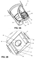
- a rotating cutting tool 21 ( FIG. 4 ) according to an aspect of the present invention has a toolholder 23 as shown in FIGS. 3A-3G .
- one or more cutting inserts 25 (e.g., FIGS. 5A-5D and 6A-6C ) are mounted to the toolholder 23.
- the cutting inserts 25 are indexable to more than one position.
- the inserts 25 are double-sided inserts and are indexable to four cutting positions.
- the toolholder 23 seen in various views in FIGS. 3A-3G , comprises a toolholder body 27 and has a longitudinal axis A ( FIG. 3E ).
- the toolholder 23 comprises at least one cutting insert receiving pocket 29 in the toolholder body 27, and ordinarily a plurality of insert receiving pockets at different circumferential and/or axial positions on the toolholder body. Three pockets are shown in FIGS. 3A and 3C .
- the pocket 29 comprises at least one bottom surface 31 (seen in greater detail in FIGS. 3B , 3D , and 3F ) that is oriented at a negative holding angle.
- an insert 25 can be shaped so that, even though it is mounted in a pocket having a negative radial holding angle ⁇ and/or axial holding angle ⁇ , its rake surface can be held at a positive radial and/or axial rake angle relative to a workpiece.
- the insert might instead be shaped so that it has a negative radial and/or axial rake angle.
- a pocket 29 has a negative, positive, or zero axial holding angle ⁇ and a negative radial holding angle ⁇
- an insert 25 in the pocket has a geometry such that it has a positive or zero axial rake angle ⁇ and a positive radial rake angle (not shown).
- the bottom surface 31 defines a negative radial holding angle ⁇ ( FIG. 3C ) with the plane PA of the longitudinal axis A.
- the same bottom surface 31 can form a negative, positive (as seen in FIG. 3G ), or zero axial holding angle ⁇ .
- the pocket 29 further includes at least one angled abutment surface 33 in the bottom surface 31.
- the angled abutment surface 33 and the bottom surface 31 are oriented at a non-zero abutment surface angle ⁇ ( FIG. 3D ) relative to each other.
- the angled abutment surface 33 can define with the bottom surface 31 an angle ⁇ substantially equal to or greater than, and opposite from, the negative holding angle at which the bottom surface is oriented so that the angled abutment surface is oriented at a substantially neutral or positive holding angle.
- the bottom surface 31 forms a negative radial holding angle ⁇ of 26°
- the angled abutment surface 33 forms an angle ⁇ with the bottom surface that is also equal to 26° so that the angled abutment surface forms a zero radial holding angle as seen in FIGS. 3C and 3D .
- a hole 32 can extend into the bottom surface 31.
- the hole 32 can be internally threaded for mating with an externally threaded bolt 34 ( FIG. 4 ) that secures the insert 25 in the pocket 29.
- the hole 32 will ordinarily extend at an angle substantially perpendicular to a plane P of the bottom surface 31.
- the angled abutment surface 33 that defines with the bottom surface 31 an angle ⁇ substantially equal to or greater than, and opposite from, the negative holding angle at which the bottom surface 31 is oriented, the angled abutment surface oriented at the substantially neutral or positive holding angle can provide additional support to resist forces on the insert that might otherwise tend to damage the bolt 34.
- the angled abutment surface 33 facilitates holding the insert 25 in place in the pocket 29 substantially regardless what kind of clamping arrangement is used.
- the angled abutment surfaces 33 in one pocket 29 are elongated and their major axes may extend parallel to each other spaced about the hole 32.
- parallel in that connection is meant that the two major axes do not intersect in a plane.
- a line through the center of the hole 32 may be perpendicular to said major axes.
- the cutting insert can be manufactured from directly pressed cemented carbide.
- cemented carbide is here meant WC, TiC, TaC, NbC, etc., in sintered combination with a binder metal such as, for instance, Co or Ni.
- the cutting insert is preferably at least partly coated with layers of, e.g., Al2O3, TiN and/or TiCN. In certain cases, it may be justified that the cutting edges comprise soldered superhard materials such as CBN or PCD.
- the angled abutment surface 33 can comprise a first surface portion 35 that defines with the bottom surface 31 a first angle ⁇ and a second surface portion 37 that defines with the bottom surface a second angle ⁇ ( FIG. 3D ) that is different from the first angle.
- the second angle ⁇ can be opposite from and equal to or, preferably, greater than the first angle ⁇ so that second surface portion defines a negative holding angle that is equal to or greater than twice as large as the negative holding angle of the bottom surface 31.
- the two first surface portions 35 in one bottom surface 31 may be substantially parallel, see Fig. 3D .
- providing the second angle ⁇ of the second surface portion 37 at a larger angle than the first angle ⁇ of the first portion 33 can be useful to prevent the second surface portion 37 from interfering with surfaces (63 and 65) on the insert 25.
- the angled abutment surfaces 33 and the first and second surfaces portions 35 and 37 can be elongated, ordinarily flat, surfaces such as are shown in, e.g., FIGS. 3B and 3F , however, they may have other shapes. For example, they may be in the shape of one or more pyramids, truncated pyramids, ridges, or serrations.
- the bottom surface 31 will ordinarily have at least two angled abutment surfaces 33.
- the first portions 35 of two angled abutment surfaces 33 are oriented at the same angle ⁇ relative to the bottom surface 31, and the second portions 37 of the two angled abutment surfaces are oriented at the same angle ⁇ relative to the bottom surface.
- the pocket 29 ordinarily also comprises at least two side abutment surfaces 39 that forms a non-zero angle with the at least one bottom surface 31.
- the at least two side abutment surfaces 39 are non-parallel to each other.
- Side supporting surfaces on side surfaces of the insert 25 support the insert against the side abutment surfaces.
- FIGS. 4 , 5A-5D, and 6A-6C show a cutting insert 25 according to an aspect of the present invention that is particularly well-suited for use in a toolholder 23 as described herein.
- the insert 25 can be a single-sided or a double-sided cutting insert. For purposes of discussion, a double-sided insert is described.
- the insert 25 is particularly well-suited for mounting in the toolholder 23 that comprises the toolholder body 27 having a longitudinal axis A, at least one cutting insert receiving pocket 29 in the toolholder body, the at least one pocket comprising at least one bottom surface 31, the at least one bottom surface being oriented at a negative holding angle, and at least one angled abutment surface 33 in the at least one bottom surface, the at least one angled abutment surface and the at least one bottom surface being oriented at an angle ⁇ relative to each other.
- the insert is receivable in the pocket 29 and is ordinarily indexable to at least four positions relative to the pocket.
- the double-sided insert 25 includes two identical supporting surfaces 41 on opposite sides of the insert.
- Each supporting surface 41 comprises a surface portion 43 for facing towards the bottom surface 31 and an angled supporting surface 45 for contacting the angled abutment surface 33.
- four identical side surfaces 47 extend between the two supporting surfaces 41. In other embodiments (not shown), additional side surfaces might be provided. At least parts of the side surfaces 47 function as side supporting surfaces and abut the side abutment surfaces 39 in the pocket 29.
- the four side surfaces 47 defining with the two supporting surfaces 41 four cutting corners 49. Each cutting corner 49 has a first edge component 51 defined by an intersection of a first one of the four side surfaces 47 with one of the two supporting surfaces 41 and a second edge component 53 defined by an intersection of a second one of the four side surfaces with the one of the two supporting surfaces.
- the first one of the four side surfaces 47 forms an acute angle ⁇ ( FIG.
- the second one of the four side surfaces 47 forms an obtuse angle ⁇ ( FIG. 5B ) with the plane PSS of the surface portion 43 of the one of the two supporting surfaces 41 with which the second one of the four side surfaces forms the second edge component 53.
- the side surfaces 47 can be, but need not be, substantially planar. In the tool shown in FIG. 4 , a portion 47a of the side surface 47 closest to the second edge component 53 forms a larger angle with the surface portion 43 than the rest of the side surface.
- the first edge component 51 is a generally radially extending edge, also referred to as a radial cutting edge
- the second edge component 53 is a generally axially extending edge, also referred to as an axial cutting edge.
- the insert 25 can be provided with a geometry such that a wedge angle defined by surface portions of the supporting surfaces 41 immediately inward of one or, ordinarily, both of the first and second cutting edge components 51 and 53 is an acute angle, even though the plane PSS of the surface portion 43 might form an obtuse angle with the side surface by the cutting edge component.
- the insert 25 ordinarily comprises a hole 55 extending through the insert and being adapted to align with the hole 32 in the toolholder 23 when the insert is received in the pocket 29.
- the bolt 34 extends through the hole 55 in the insert 25 and has threads that mate with threads of the hole 32 in the toolholder. A lower portion of the head 57 of the bolt 34 contacts the insert 25, usually contacting an angled surface 59 of the hole 55 so that the head of the bolt does not extend above the supporting surface 41 of the insert.
- the at least one bottom surface 31 can define, for example, a negative radial holding angle p with a plane PA of the longitudinal axis A.
- the insert 25 can comprise an axial cutting edge 53 and rake surface 61 shaped so that, when the insert is received in the at least one pocket 29, the rake surface along the axial cutting edge is held at a positive or zero rake angle.
- the resulting tool 21 provides a highly desirable combination of cutting properties and strength.
- the angled abutment surface 33 defines with the bottom surface 31 the abutment surface angle ⁇ that is substantially equal to or greater than, and opposite from, the negative holding angle at which the bottom surface is oriented so that the angled abutment surface is oriented at a substantially neutral or positive holding angle.
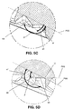
- a plane PAS (see, e.g., FIG. 5D ) of the angled supporting surface 45, in turn, preferably intersects with a plane PSS of the surface portion 43 along a line of intersection LI defines a supporting surface angle ⁇ ' with the surface portion 43 equal to the abutment surface angle ⁇ so that the angled supporting surface 45 will be in surface-to-surface contact with the angled abutment surface 33.
- the angled supporting surface 45 ordinarily comprises a first surface portion 63 that defines with the surface portion 43 (or the plane PSS of the surface portion as shown in FIGS. 5C and 5D which, for purposes of the present discussion, shall be considered to be the same thing as the surface portion, even though the supporting surface need not be planar) the supporting surface angle ⁇ ' and a second surface portion 65 that defines with the surface portion (or the plane PSS of the surface portion) a second angle ⁇ ' that is different from the supporting surface angle.
- the second angle ⁇ ' is ordinarily equal to 180° minus the supporting surface angle ⁇ '.
- the second surface portion 65 is disposed further from a center of the insert 25 than the first surface portion.
- each supporting surface 41 of the insert will ordinarily include at least two angled supporting surfaces 45 in the surface portion 43.
- the at least two angled supporting surfaces 45 are oriented at least at one angle ⁇ ' relative to the surface portion 43 and can be mutually parallel and spaced apart about a center of the cutting insert.
- the at least two angled supporting surfaces 45 will ordinarily be oriented at the same angle ⁇ ' relative to the surface portion.
- FIG. 4 shows how an insert 25 with a pair of angled supporting surfaces 45 with first and second surface portions 63 and 65 can be arranged to facilitate indexing of the insert 25.
- the insert 25 can be seated in the pocket 29 so that the first surface portion 63 of a first one of the angled supporting surfaces 45 is in surface-to-surface contact with the first portion 35 of a radially innermost one of the angled abutment surfaces 33 and the second surface portion 65 of that first one of the angled supporting surfaces 45 will be spaced from the second portion 37 of that innermost one of the angled abutment surfaces.
- the second surface portion 65 of that second one of the angled supporting surfaces 45 is in surface-to-surface contact with the first portion 35 of the radially outermost one of the angled abutment surfaces 33 and the first surface portion 63 of that second one of the angled supporting surfaces 45 will be spaced from the second portion 37 of the outermost one of the angled abutment surfaces.
- first surface portion 63 of the second angled supporting surface 45 will abut the first portion 35 of the radially innermost angled abutment surface 33 and the second surface portion 65 of the first angled supporting surface 45 will abut the first surface portion 35 of the radially outermost angled abutment surface 33.
- the two supporting surfaces 41 can be oriented at 90° angles relative to each other, i.e., the lines of intersection LI between the surface portions 43 and the angled supporting surfaces 45 are perpendicular to each other.
- the cutting insert 25 can have four cutting corners 49.
- Two cutting corners 49 of the four cutting corners are disposed at two diagonally opposite corners of the insert, on opposite sides of the insert. It will be appreciated that an insert with four side surfaces and four corners might also have eight cutting corners, and that other insert designs involving more or fewer side surfaces, corners, and cutting corners can be provided
- the bottom surface 31 defines a negative, positive, or zero axial holding angle ⁇
- the insert 25 comprises a radial cutting edge 51 and rake surface 61 shaped so that, when the insert is received in the at least one pocket, the rake surface along the radial cutting edge is held at a positive rake angle.
- the insert 25 can provide good cutting characteristics. This can be coupled with the provision of an acute angle ⁇ ( FIG. 5B ) between the first one of the four side surfaces 47 and the plane PSS of the surface portion 43 of the supporting surface 41, which can further facilitate cutting.
- a turning tool has a toolholder with an abutment surface that defines a negative holding angle relative to the rotating workpiece
- the abutment surface of the toolholder and the corresponding supporting surface of the insert to be mounted on the toolholder can be provided with angled abutment and angled supporting surfaces.
- Such a structure help distribute forces that would otherwise act on a bolt holding the insert to the toolholder.
Landscapes
- Engineering & Computer Science (AREA)
- Mechanical Engineering (AREA)
- Cutting Tools, Boring Holders, And Turrets (AREA)
- Knives (AREA)
- Milling Processes (AREA)
Claims (15)
- Insert de coupe (25), comprenant
deux surfaces de support (41),
quatre surfaces latérales (47) entre les deux surfaces de support (41), chaque surface latérale (47) des quatre surfaces latérales ayant une intersection avec deux autres surfaces latérales des quatre surfaces latérales pour former quatre coins (67),
les quatre surfaces latérales (47) ayant une intersection avec les deux surfaces de support (41) pour former, au niveau de deux des quatre coins (67), quatre coins coupants (49), chaque coin coupant comprenant une première et une deuxième composante d'arête de coupe (51 et 53), et pour former au niveau de deux autres des quatre coins, quatre coins non coupants,
caractérisé en ce que chaque surface de support (41) comprend une partie de surface (43) et une surface de support inclinée (45), un plan de la surface de support inclinée ayant une intersection avec un plan (PSS) de la partie de surface (43) le long d'une ligne d'intersection et formant un angle non nul (β') avec le plan (PSS) de la partie de surface (43), dans lequel la ligne d'intersection sur une première des deux surfaces de support (41) est substantiellement perpendiculaire à la ligne d'intersection d'une deuxième des deux surfaces de support (41). - Insert de coupe (25) selon la revendication 1, caractérisé en ce que le plan (PSS) de chaque partie de surface (43) forme un angle obtus (Ψ) avec deux des quatre surfaces latérales (47).
- Insert de coupe (25) selon l'une quelconque des revendications 1 et 2, caractérisé en ce que le plan (PSS) de chaque partie de surface (43) forme un angle aigu (Σ) avec deux des quatre surfaces latérales (47).
- Insert de coupe (25) selon l'une quelconque des revendications 1 à 3, caractérisé en ce qu'un angle de taillant au niveau de chacune des première et deuxième composantes d'arête de coupe (51 et 53) est un angle aigu.
- Insert de coupe selon l'une quelconque des revendications 1 à 4, caractérisé en ce que la surface de support inclinée (45) comprend une première partie de surface (65) qui définit avec le plan (PSS) de la partie de surface (43) un angle de surface de support (β') et une deuxième partie de surface (67) qui définit avec le plan (PSS) de la partie de surface (43) un deuxième angle (φ') qui est différent de l'angle de surface de support (β').
- Insert de coupe (25) selon la revendication 5, caractérisé en ce que le deuxième angle (φ') est égal à 180° moins l'angle de surface de support (β').
- Insert de coupe (25) selon l'une quelconque des revendications 1 à 6, caractérisé en ce que l'insert comprend au moins deux surfaces de support inclinées (45) dans la partie de surface (43), les au moins deux surfaces de support inclinées (45) étant orientées au moins suivant un angle (β') par rapport à la partie de surface (43) et étant parallèles et écartées par rapport à un centre (IA) de l'insert de coupe (25).
- Insert de coupe (25) selon la revendication 7, caractérisé en ce que les au moins deux surfaces de support inclinées (45) sont orientées suivant le même angle (β') par rapport à la partie de surface (43).
- Porte-outil (23) pour un outil de coupe rotatif (21), comprenant :un corps de porte-outil (27) ayant un axe longitudinal (A) ;au moins un logement de réception d'insert de coupe (29) dans le corps de porte-outil (27), le au moins un logement (29) comprenant au moins une surface inférieure (31), la au moins une surface inférieure (31) étant orientée suivant un angle de maintien négatif, ledit logement (29) comprenant au moins deux surfaces de butée latérale non parallèles (39) qui forment un angle non nul avec la au moins une surface inférieure (31) ;caractérisé en ce que le porte-outil (23) comprend au moins une surface de butée inclinée (33) dans la au moins une surface inférieure (31), la au moins une surface de butée inclinée (33) et la au moins une surface inférieure (31) étant orientées suivant un angle de surface de butée non nul (β) l'une par rapport à l'autre, et en ce que l'angle de surface de butée (β) est substantiellement supérieur ou égal, et opposé, par rapport à un angle de maintien (ρ) suivant lequel la au moins une surface inférieure (31) est orientée de sorte que la au moins une surface de butée inclinée (33) soit orientée suivant un angle de maintien substantiellement neutre ou positif.
- Porte-outil (23) selon la revendication 9, caractérisé en ce que le porte-outil comprend un trou (32) s'étendant dans la au moins une surface inférieure (31) suivant un angle substantiellement perpendiculaire à un plan (P) de la surface inférieure (31).
- Porte-outil (23) selon l'une quelconque des revendications 9 et 10, caractérisé en ce que la au moins une surface inférieure (31) définit un angle de maintien radial négatif (ρ) par rapport à l'axe longitudinal (A), et en ce que l'angle de surface de butée (β) est substantiellement supérieur ou égal, et opposé, par rapport à l'angle de maintien négatif (ρ) suivant lequel la au moins une surface inférieure (31) est orientée de sorte que la au moins une surface de butée inclinée (33) soit orientée suivant un angle substantiellement neutre ou positif.
- Outil de coupe (21), comprenant
un porte-outil (23) pour un outil de coupe rotatif (21), comprenant un corps de porte-outil (27) ayant un axe longitudinal (A), au moins un logement de réception d'insert de coupe (29) dans le corps de porte-outil (27), le au moins un logement (29) comprenant au moins une surface inférieure (31), la au moins une surface inférieure (31) étant orientée suivant un angle de maintien négatif, et
un insert de coupe (25) monté dans le logement de réception d'insert de coupe (29), l'insert de coupe comprenant au moins une surface de support (41) tournée vers la au moins une surface inférieure (31),
caractérisé en ce que le porte-outil (23) comprend au moins une surface de butée inclinée (33) dans la au moins une surface inférieure (31) et en ce que l'insert (25) comprend au moins une partie de surface (43) et au moins une surface de support inclinée (45) dans la au moins une surface de support (41), la au moins une surface de butée inclinée (33) et la au moins une surface inférieure (31) étant orientées suivant un angle de surface de butée non nul (β) l'une par rapport à l'autre, et en ce que la au moins une surface de support inclinée (45) et la au moins une surface de support (43) étant orientée suivant un angle de surface de support non nul (β') l'une par rapport à l'autre, le au moins un angle de surface de butée (β) et le au moins un angle de surface de support (β') étant égaux, et en ce que l'angle de surface de butée (β) est substantiellement supérieur ou égal, et opposé, par rapport à un angle de maintien (ρ) suivant lequel la au moins une surface inférieure (31) est orientée de sorte que la au moins une surface de butée inclinée (33) soit orientée suivant un angle de maintien substantiellement neutre ou positif. - Outil de coupe (21) selon la revendication 12, caractérisé en ce que la au moins une surface inférieure (31) définit un angle de maintien radial négatif (ρ) par rapport à l'axe longitudinal (A), et en ce que l'angle de surface de butée (β) est substantiellement supérieur ou égal, et opposé, par rapport à l'angle de maintien négatif (p) suivant lequel la au moins une surface inférieure (31) est orientée de sorte que la au moins une surface de butée inclinée (33) soit orientée suivant un angle de maintien substantiellement neutre ou positif.
- Outil de coupe (21) selon l'une quelconque des revendications 12 et 13, dans lequel l'insert (25) a au moins un coin coupant (49) et est monté dans le logement (29) de sorte qu'un coin coupant (49) soit dans une position de travail, le coin coupant (49) dans la position de travail comprenant une partie d'arête s'étendant axialement (53) et une partie d'arête s'étendant radialement (51), l'insert (25) étant formé et monté de sorte qu'au moins des parties de la au moins une surface de support (41) vers l'intérieur de la partie d'arête s'étendant axialement (53) et de la partie d'arête s'étendant radialement (51) forment des angles d'attaque axiaux et radiaux positifs.
- Outil de coupe (21) selon l'une quelconque des revendications 12 à 14, dans lequel l'insert (25) a un plan (PSS) de la au moins une partie de surface (43) qui forme un angle obtus avec une surface de dépouille (47) de l'insert (25) à une position adjacente à au moins l'une de la partie d'arête s'étendant axialement (53) et de la partie d'arête s'étendant radialement (51).
Priority Applications (8)
| Application Number | Priority Date | Filing Date | Title |
|---|---|---|---|
| EP12151084.6A EP2614907B1 (fr) | 2012-01-13 | 2012-01-13 | Insert de découpe avec surface de support en biais, porte-outil avec surface de butée en biais et outil de découpe |
| KR1020147022374A KR101982371B1 (ko) | 2012-01-13 | 2012-12-20 | 각진 지지면을 가진 절삭 인서트, 각진 인접면을 가진 공구홀더, 및 절삭 공구 |
| CN201280066826.7A CN104039487B (zh) | 2012-01-13 | 2012-12-20 | 具有成角支承表面的切削刀片、具有成角抵接表面的刀杆以及刀具 |
| RU2014133157A RU2014133157A (ru) | 2012-01-13 | 2012-12-20 | Режущая пластина с наклонной опорной поверхностью, державка с наклонной несущей поверхностью и режущий инструмент |
| PCT/EP2012/076273 WO2013104506A1 (fr) | 2012-01-13 | 2012-12-20 | Plaquette de coupe avec surface d'appui inclinée, porte-outil avec surface de butée inclinée, et outil de coupe |
| BR112014017328A BR112014017328A8 (pt) | 2012-01-13 | 2012-12-20 | pastilha de corte com superfície de suporte angulada, suporte de ferramenta com superfície de apoio angulada e ferramenta de corte |
| US14/371,811 US9138815B2 (en) | 2012-01-13 | 2012-12-20 | Cutting insert with angled supporting surface, toolholder with angled abutment surface, and cutting tool |
| IN1389/KOLNP/2014A IN2014KN01389A (en) | 2012-01-13 | 2014-07-01 | Cutting insert with angled supporting surface toolholder with angled abutment surface and cutting tool |
Applications Claiming Priority (1)
| Application Number | Priority Date | Filing Date | Title |
|---|---|---|---|
| EP12151084.6A EP2614907B1 (fr) | 2012-01-13 | 2012-01-13 | Insert de découpe avec surface de support en biais, porte-outil avec surface de butée en biais et outil de découpe |
Publications (2)
| Publication Number | Publication Date |
|---|---|
| EP2614907A1 EP2614907A1 (fr) | 2013-07-17 |
| EP2614907B1 true EP2614907B1 (fr) | 2016-11-30 |
Family
ID=47553006
Family Applications (1)
| Application Number | Title | Priority Date | Filing Date |
|---|---|---|---|
| EP12151084.6A Active EP2614907B1 (fr) | 2012-01-13 | 2012-01-13 | Insert de découpe avec surface de support en biais, porte-outil avec surface de butée en biais et outil de découpe |
Country Status (8)
| Country | Link |
|---|---|
| US (1) | US9138815B2 (fr) |
| EP (1) | EP2614907B1 (fr) |
| KR (1) | KR101982371B1 (fr) |
| CN (1) | CN104039487B (fr) |
| BR (1) | BR112014017328A8 (fr) |
| IN (1) | IN2014KN01389A (fr) |
| RU (1) | RU2014133157A (fr) |
| WO (1) | WO2013104506A1 (fr) |
Cited By (1)
| Publication number | Priority date | Publication date | Assignee | Title |
|---|---|---|---|---|
| RU2785865C2 (ru) * | 2018-03-28 | 2022-12-14 | Искар Лтд. | Режущий инструмент и режущая вставка, имеющие сопрягаемые элементы взаимодействия для эксцентрической установки |
Families Citing this family (16)
| Publication number | Priority date | Publication date | Assignee | Title |
|---|---|---|---|---|
| USRE46858E1 (en) | 2009-02-27 | 2018-05-22 | No Screw Ltd. | Cutting tool, cutting tool holder and cutting insert therefor |
| US9120154B2 (en) * | 2013-02-14 | 2015-09-01 | Iscar, Ltd. | Single-sided square-shaped indexable cutting insert and cutting tool |
| EP3041632B1 (fr) | 2013-09-03 | 2023-06-07 | No Screw Ltd. | Mécanisme de montage pour une plaquette de coupe, plaquette de coupe associée et outil de coupe utilisant ladite plaquette |
| US11376675B2 (en) | 2014-04-23 | 2022-07-05 | Korloy Inc. | Cutting tool having partially-removed film formed thereon |
| KR101537718B1 (ko) | 2014-04-23 | 2015-07-20 | 한국야금 주식회사 | 부분적으로 제거된 피막이 형성된 절삭공구 |
| EP3006141B1 (fr) | 2014-10-09 | 2021-09-29 | Seco Tools Ab | Plaquette de coupe indexable à double face pour le tournage et outil de tournage |
| JP5999586B2 (ja) * | 2014-10-16 | 2016-09-28 | 株式会社タンガロイ | 切削インサート及び刃先交換式回転切削工具 |
| EP3025813B1 (fr) * | 2014-11-28 | 2020-04-08 | Sandvik Intellectual Property AB | Outil et insert de coupe pour usinage |
| EP3253517A1 (fr) | 2015-02-04 | 2017-12-13 | No Screw Ltd. | Outil de coupe comprenant un porte-outil de coupe et un insert de coupe pour celui-ci |
| JP6966327B2 (ja) | 2015-04-30 | 2021-11-17 | ノー スクリュー リミテッド | 切削工具、切削インサート及び切削工具ホルダ |
| EP3311946B1 (fr) * | 2015-06-19 | 2020-02-19 | Tungaloy Corporation | Corps d'outil en combinaison avec insert de coupe et outil de coupe |
| EP3677368B1 (fr) | 2017-08-30 | 2023-09-20 | MOLDINO Tool Engineering, Ltd. | Insert de coupe et fraise à bout sphérique à bord de coupe remplaçable |
| US10406611B1 (en) * | 2018-03-28 | 2019-09-10 | Iscar, Ltd. | Cutting tool and cutting insert having complementary engagement features for eccentric mounting |
| CN112108697B (zh) | 2019-06-20 | 2024-08-06 | 肯纳金属印度有限公司 | 具有容纳间隙角不同的切割插入件的凹穴的工具固持器 |
| AT16933U1 (de) * | 2019-07-11 | 2020-12-15 | Ceratizit Austria Gmbh | Doppelseitiger Schneideinsatz zum Fräsen |
| CN117696998B (zh) * | 2024-02-06 | 2024-05-24 | 赣州澳克泰工具技术有限公司 | 一种刀片及切削刀具 |
Citations (1)
| Publication number | Priority date | Publication date | Assignee | Title |
|---|---|---|---|---|
| WO2004048021A1 (fr) * | 2002-11-26 | 2004-06-10 | Iscar Ltd. | Plaquette de coupe et outil de coupe |
Family Cites Families (18)
| Publication number | Priority date | Publication date | Assignee | Title |
|---|---|---|---|---|
| US5158401A (en) * | 1988-03-21 | 1992-10-27 | Gte Valenite Corporation | Indexable insert for roughing and finishing |
| DE4304071C1 (de) * | 1993-02-11 | 1994-06-23 | Fette Wilhelm Gmbh | Planfräser |
| JP3317089B2 (ja) * | 1995-06-01 | 2002-08-19 | 三菱マテリアル株式会社 | スローアウェイチップ及びスローアウェイ式カッタ |
| DE19848045C2 (de) * | 1998-10-17 | 2002-01-31 | Fette Wilhelm Gmbh | Wendeplattenfräser |
| FI116456B (fi) | 2000-12-12 | 2005-11-30 | Tauno Kulojaervi | Menetelmä ja sovitelma ajoneuvon runkopalkkien kiinnittämiseksi |
| IL144154A0 (en) * | 2001-07-05 | 2002-05-23 | Iscar Ltd | Cutting tool and cutting insert therefor |
| DE10159512A1 (de) * | 2001-12-04 | 2003-06-12 | Kennametal Inc | Zerspanungswerkzeug |
| DE10312922B4 (de) * | 2003-03-22 | 2006-02-16 | Walter Ag | Schneidplatte und Fräswerkzeug |
| SE529396C2 (sv) * | 2005-12-08 | 2007-07-31 | Sandvik Intellectual Property | Verktyg och skär för spånavskiljande bearbetning med sekundära ingreppsmedel |
| SE530808C2 (sv) * | 2007-01-31 | 2008-09-16 | Sandvik Intellectual Property | Verktyg för spånavskiljande bearbetning, samt skär och grundkropp härför |
| SE531502C2 (sv) * | 2007-06-05 | 2009-04-28 | Sandvik Intellectual Property | Verktyg för spånavskiljande bearbetning samt grundkropp och indexerbart skär härför |
| KR101237168B1 (ko) | 2008-06-13 | 2013-02-25 | 대구텍 유한회사 | 절삭 삽입체, 절삭 공구용 카트리지, 그리고 절삭 공구 |
| DE202008018646U1 (de) * | 2008-08-31 | 2017-03-24 | Iscar Ltd. | Schneideinsatz |
| KR101262566B1 (ko) * | 2008-12-11 | 2013-05-08 | 대구텍 유한회사 | 절삭 공구 |
| WO2010092807A1 (fr) * | 2009-02-13 | 2010-08-19 | 株式会社タンガロイ | Outil coupant à inserts coupants et insert coupant associés |
| JP5522253B2 (ja) * | 2010-03-30 | 2014-06-18 | 三菱マテリアル株式会社 | 刃先交換式切削工具 |
| JP5515966B2 (ja) * | 2010-03-30 | 2014-06-11 | 三菱マテリアル株式会社 | 切削インサートおよび刃先交換式切削工具 |
| US9475134B2 (en) * | 2011-12-19 | 2016-10-25 | Iscar, Ltd. | Cutting insert and cutting tool |
-
2012
- 2012-01-13 EP EP12151084.6A patent/EP2614907B1/fr active Active
- 2012-12-20 BR BR112014017328A patent/BR112014017328A8/pt not_active Application Discontinuation
- 2012-12-20 WO PCT/EP2012/076273 patent/WO2013104506A1/fr active Application Filing
- 2012-12-20 KR KR1020147022374A patent/KR101982371B1/ko active IP Right Grant
- 2012-12-20 CN CN201280066826.7A patent/CN104039487B/zh active Active
- 2012-12-20 RU RU2014133157A patent/RU2014133157A/ru not_active Application Discontinuation
- 2012-12-20 US US14/371,811 patent/US9138815B2/en active Active
-
2014
- 2014-07-01 IN IN1389/KOLNP/2014A patent/IN2014KN01389A/en unknown
Patent Citations (1)
| Publication number | Priority date | Publication date | Assignee | Title |
|---|---|---|---|---|
| WO2004048021A1 (fr) * | 2002-11-26 | 2004-06-10 | Iscar Ltd. | Plaquette de coupe et outil de coupe |
Cited By (1)
| Publication number | Priority date | Publication date | Assignee | Title |
|---|---|---|---|---|
| RU2785865C2 (ru) * | 2018-03-28 | 2022-12-14 | Искар Лтд. | Режущий инструмент и режущая вставка, имеющие сопрягаемые элементы взаимодействия для эксцентрической установки |
Also Published As
| Publication number | Publication date |
|---|---|
| RU2014133157A (ru) | 2016-03-10 |
| WO2013104506A1 (fr) | 2013-07-18 |
| CN104039487B (zh) | 2016-12-21 |
| KR101982371B1 (ko) | 2019-05-27 |
| US20150016900A1 (en) | 2015-01-15 |
| CN104039487A (zh) | 2014-09-10 |
| US9138815B2 (en) | 2015-09-22 |
| BR112014017328A8 (pt) | 2017-07-04 |
| KR20140106762A (ko) | 2014-09-03 |
| BR112014017328A2 (pt) | 2017-06-13 |
| IN2014KN01389A (en) | 2015-10-16 |
| EP2614907A1 (fr) | 2013-07-17 |
Similar Documents
| Publication | Publication Date | Title |
|---|---|---|
| EP2614907B1 (fr) | Insert de découpe avec surface de support en biais, porte-outil avec surface de butée en biais et outil de découpe | |
| US7494303B2 (en) | Cutting insert and a tool | |
| EP3233341B1 (fr) | Insert de coupe renforcé à double face et outil de coupe avec insert de coupe renforcé à double face | |
| EP2977136B1 (fr) | Plaquette de coupe, et outil de coupe à bord de coupe remplaçable | |
| US9039335B2 (en) | Indexable, double-sided cutting insert and cutting tool including such an insert | |
| US7909544B2 (en) | Cutting insert and tool for chip removing machining | |
| US7901161B2 (en) | Cutting insert and tool for chip removing machining | |
| US8882407B2 (en) | Indexable cutting insert | |
| EP1931487B1 (fr) | Mise de fraisage | |
| EP1677934B1 (fr) | Insert de fraise a coupe tangentielle et fraise | |
| US8974154B2 (en) | Cutting insert and shim for milling cutters | |
| EP2101947B1 (fr) | Insert de coupe et outil de coupe | |
| US10144069B2 (en) | Indexable milling insert having side supporting valley, and a milling tool | |
| US20130259586A1 (en) | Cutting insert with grooved surface defining plural support surfaces | |
| US10682713B2 (en) | Indexable single-sided cutting insert with means for preventing improper mounting of the insert, and cutting tool including such an insert | |
| EP2583775A1 (fr) | Plaquette de coupe et outil de coupe rotatif indexable | |
| EP2450138B1 (fr) | Insert de découpe avec surface rainurée définissant plusieurs surfaces de support | |
| US8540462B2 (en) | Shim plate for tools for cutting machining as well as a tool | |
| EP3243589A1 (fr) | Insert de coupe indexable avec des moyens pour empêcher un mauvais montage de l'insert et outil de coupe comprenant un tel insert | |
| EP3243590A1 (fr) | Insert de coupe indexable à grand rayon de bec | |
| EP2383061A1 (fr) | Outil de découpe avec agencement de cale |
Legal Events
| Date | Code | Title | Description |
|---|---|---|---|
| PUAI | Public reference made under article 153(3) epc to a published international application that has entered the european phase |
Free format text: ORIGINAL CODE: 0009012 |
|
| 17P | Request for examination filed |
Effective date: 20120113 |
|
| AK | Designated contracting states |
Kind code of ref document: A1 Designated state(s): AL AT BE BG CH CY CZ DE DK EE ES FI FR GB GR HR HU IE IS IT LI LT LU LV MC MK MT NL NO PL PT RO RS SE SI SK SM TR |
|
| AX | Request for extension of the european patent |
Extension state: BA ME |
|
| RBV | Designated contracting states (corrected) |
Designated state(s): AL AT BE BG CH CY CZ DE DK EE ES FI FR GB GR HR HU IE IS IT LI LT LU LV MC MK MT NL NO PL PT RO RS SE SI SK SM TR |
|
| GRAP | Despatch of communication of intention to grant a patent |
Free format text: ORIGINAL CODE: EPIDOSNIGR1 |
|
| INTG | Intention to grant announced |
Effective date: 20160706 |
|
| GRAS | Grant fee paid |
Free format text: ORIGINAL CODE: EPIDOSNIGR3 |
|
| GRAA | (expected) grant |
Free format text: ORIGINAL CODE: 0009210 |
|
| AK | Designated contracting states |
Kind code of ref document: B1 Designated state(s): AL AT BE BG CH CY CZ DE DK EE ES FI FR GB GR HR HU IE IS IT LI LT LU LV MC MK MT NL NO PL PT RO RS SE SI SK SM TR |
|
| REG | Reference to a national code |
Ref country code: CH Ref legal event code: EP Ref country code: GB Ref legal event code: FG4D |
|
| REG | Reference to a national code |
Ref country code: AT Ref legal event code: REF Ref document number: 849326 Country of ref document: AT Kind code of ref document: T Effective date: 20161215 |
|
| REG | Reference to a national code |
Ref country code: IE Ref legal event code: FG4D |
|
| REG | Reference to a national code |
Ref country code: DE Ref legal event code: R096 Ref document number: 602012025924 Country of ref document: DE |
|
| REG | Reference to a national code |
Ref country code: FR Ref legal event code: PLFP Year of fee payment: 6 |
|
| PG25 | Lapsed in a contracting state [announced via postgrant information from national office to epo] |
Ref country code: LV Free format text: LAPSE BECAUSE OF FAILURE TO SUBMIT A TRANSLATION OF THE DESCRIPTION OR TO PAY THE FEE WITHIN THE PRESCRIBED TIME-LIMIT Effective date: 20161130 |
|
| REG | Reference to a national code |
Ref country code: LT Ref legal event code: MG4D |
|
| REG | Reference to a national code |
Ref country code: NL Ref legal event code: MP Effective date: 20161130 |
|
| REG | Reference to a national code |
Ref country code: AT Ref legal event code: MK05 Ref document number: 849326 Country of ref document: AT Kind code of ref document: T Effective date: 20161130 |
|
| PG25 | Lapsed in a contracting state [announced via postgrant information from national office to epo] |
Ref country code: NO Free format text: LAPSE BECAUSE OF FAILURE TO SUBMIT A TRANSLATION OF THE DESCRIPTION OR TO PAY THE FEE WITHIN THE PRESCRIBED TIME-LIMIT Effective date: 20170228 Ref country code: GR Free format text: LAPSE BECAUSE OF FAILURE TO SUBMIT A TRANSLATION OF THE DESCRIPTION OR TO PAY THE FEE WITHIN THE PRESCRIBED TIME-LIMIT Effective date: 20170301 Ref country code: SE Free format text: LAPSE BECAUSE OF FAILURE TO SUBMIT A TRANSLATION OF THE DESCRIPTION OR TO PAY THE FEE WITHIN THE PRESCRIBED TIME-LIMIT Effective date: 20161130 Ref country code: LT Free format text: LAPSE BECAUSE OF FAILURE TO SUBMIT A TRANSLATION OF THE DESCRIPTION OR TO PAY THE FEE WITHIN THE PRESCRIBED TIME-LIMIT Effective date: 20161130 |
|
| PG25 | Lapsed in a contracting state [announced via postgrant information from national office to epo] |
Ref country code: PL Free format text: LAPSE BECAUSE OF FAILURE TO SUBMIT A TRANSLATION OF THE DESCRIPTION OR TO PAY THE FEE WITHIN THE PRESCRIBED TIME-LIMIT Effective date: 20161130 Ref country code: HR Free format text: LAPSE BECAUSE OF FAILURE TO SUBMIT A TRANSLATION OF THE DESCRIPTION OR TO PAY THE FEE WITHIN THE PRESCRIBED TIME-LIMIT Effective date: 20161130 Ref country code: AT Free format text: LAPSE BECAUSE OF FAILURE TO SUBMIT A TRANSLATION OF THE DESCRIPTION OR TO PAY THE FEE WITHIN THE PRESCRIBED TIME-LIMIT Effective date: 20161130 Ref country code: RS Free format text: LAPSE BECAUSE OF FAILURE TO SUBMIT A TRANSLATION OF THE DESCRIPTION OR TO PAY THE FEE WITHIN THE PRESCRIBED TIME-LIMIT Effective date: 20161130 Ref country code: PT Free format text: LAPSE BECAUSE OF FAILURE TO SUBMIT A TRANSLATION OF THE DESCRIPTION OR TO PAY THE FEE WITHIN THE PRESCRIBED TIME-LIMIT Effective date: 20170330 Ref country code: BE Free format text: LAPSE BECAUSE OF NON-PAYMENT OF DUE FEES Effective date: 20170131 Ref country code: FI Free format text: LAPSE BECAUSE OF FAILURE TO SUBMIT A TRANSLATION OF THE DESCRIPTION OR TO PAY THE FEE WITHIN THE PRESCRIBED TIME-LIMIT Effective date: 20161130 Ref country code: ES Free format text: LAPSE BECAUSE OF FAILURE TO SUBMIT A TRANSLATION OF THE DESCRIPTION OR TO PAY THE FEE WITHIN THE PRESCRIBED TIME-LIMIT Effective date: 20161130 |
|
| PG25 | Lapsed in a contracting state [announced via postgrant information from national office to epo] |
Ref country code: NL Free format text: LAPSE BECAUSE OF FAILURE TO SUBMIT A TRANSLATION OF THE DESCRIPTION OR TO PAY THE FEE WITHIN THE PRESCRIBED TIME-LIMIT Effective date: 20161130 |
|
| PG25 | Lapsed in a contracting state [announced via postgrant information from national office to epo] |
Ref country code: EE Free format text: LAPSE BECAUSE OF FAILURE TO SUBMIT A TRANSLATION OF THE DESCRIPTION OR TO PAY THE FEE WITHIN THE PRESCRIBED TIME-LIMIT Effective date: 20161130 Ref country code: CZ Free format text: LAPSE BECAUSE OF FAILURE TO SUBMIT A TRANSLATION OF THE DESCRIPTION OR TO PAY THE FEE WITHIN THE PRESCRIBED TIME-LIMIT Effective date: 20161130 Ref country code: DK Free format text: LAPSE BECAUSE OF FAILURE TO SUBMIT A TRANSLATION OF THE DESCRIPTION OR TO PAY THE FEE WITHIN THE PRESCRIBED TIME-LIMIT Effective date: 20161130 Ref country code: RO Free format text: LAPSE BECAUSE OF FAILURE TO SUBMIT A TRANSLATION OF THE DESCRIPTION OR TO PAY THE FEE WITHIN THE PRESCRIBED TIME-LIMIT Effective date: 20161130 Ref country code: SK Free format text: LAPSE BECAUSE OF FAILURE TO SUBMIT A TRANSLATION OF THE DESCRIPTION OR TO PAY THE FEE WITHIN THE PRESCRIBED TIME-LIMIT Effective date: 20161130 |
|
| PG25 | Lapsed in a contracting state [announced via postgrant information from national office to epo] |
Ref country code: BG Free format text: LAPSE BECAUSE OF FAILURE TO SUBMIT A TRANSLATION OF THE DESCRIPTION OR TO PAY THE FEE WITHIN THE PRESCRIBED TIME-LIMIT Effective date: 20170228 Ref country code: SM Free format text: LAPSE BECAUSE OF FAILURE TO SUBMIT A TRANSLATION OF THE DESCRIPTION OR TO PAY THE FEE WITHIN THE PRESCRIBED TIME-LIMIT Effective date: 20161130 Ref country code: BE Free format text: LAPSE BECAUSE OF FAILURE TO SUBMIT A TRANSLATION OF THE DESCRIPTION OR TO PAY THE FEE WITHIN THE PRESCRIBED TIME-LIMIT Effective date: 20161130 |
|
| REG | Reference to a national code |
Ref country code: CH Ref legal event code: PL Ref country code: DE Ref legal event code: R097 Ref document number: 602012025924 Country of ref document: DE |
|
| PG25 | Lapsed in a contracting state [announced via postgrant information from national office to epo] |
Ref country code: MC Free format text: LAPSE BECAUSE OF FAILURE TO SUBMIT A TRANSLATION OF THE DESCRIPTION OR TO PAY THE FEE WITHIN THE PRESCRIBED TIME-LIMIT Effective date: 20161130 |
|
| PLBE | No opposition filed within time limit |
Free format text: ORIGINAL CODE: 0009261 |
|
| STAA | Information on the status of an ep patent application or granted ep patent |
Free format text: STATUS: NO OPPOSITION FILED WITHIN TIME LIMIT |
|
| PG25 | Lapsed in a contracting state [announced via postgrant information from national office to epo] |
Ref country code: CH Free format text: LAPSE BECAUSE OF NON-PAYMENT OF DUE FEES Effective date: 20170131 Ref country code: LI Free format text: LAPSE BECAUSE OF NON-PAYMENT OF DUE FEES Effective date: 20170131 |
|
| REG | Reference to a national code |
Ref country code: IE Ref legal event code: MM4A |
|
| 26N | No opposition filed |
Effective date: 20170831 |
|
| PG25 | Lapsed in a contracting state [announced via postgrant information from national office to epo] |
Ref country code: LU Free format text: LAPSE BECAUSE OF NON-PAYMENT OF DUE FEES Effective date: 20170113 Ref country code: SI Free format text: LAPSE BECAUSE OF FAILURE TO SUBMIT A TRANSLATION OF THE DESCRIPTION OR TO PAY THE FEE WITHIN THE PRESCRIBED TIME-LIMIT Effective date: 20161130 |
|
| REG | Reference to a national code |
Ref country code: FR Ref legal event code: PLFP Year of fee payment: 7 |
|
| PG25 | Lapsed in a contracting state [announced via postgrant information from national office to epo] |
Ref country code: IE Free format text: LAPSE BECAUSE OF NON-PAYMENT OF DUE FEES Effective date: 20170113 |
|
| PG25 | Lapsed in a contracting state [announced via postgrant information from national office to epo] |
Ref country code: MT Free format text: LAPSE BECAUSE OF NON-PAYMENT OF DUE FEES Effective date: 20170113 |
|
| PG25 | Lapsed in a contracting state [announced via postgrant information from national office to epo] |
Ref country code: HU Free format text: LAPSE BECAUSE OF FAILURE TO SUBMIT A TRANSLATION OF THE DESCRIPTION OR TO PAY THE FEE WITHIN THE PRESCRIBED TIME-LIMIT; INVALID AB INITIO Effective date: 20120113 |
|
| PG25 | Lapsed in a contracting state [announced via postgrant information from national office to epo] |
Ref country code: CY Free format text: LAPSE BECAUSE OF NON-PAYMENT OF DUE FEES Effective date: 20161130 |
|
| PG25 | Lapsed in a contracting state [announced via postgrant information from national office to epo] |
Ref country code: MK Free format text: LAPSE BECAUSE OF FAILURE TO SUBMIT A TRANSLATION OF THE DESCRIPTION OR TO PAY THE FEE WITHIN THE PRESCRIBED TIME-LIMIT Effective date: 20161130 |
|
| PG25 | Lapsed in a contracting state [announced via postgrant information from national office to epo] |
Ref country code: TR Free format text: LAPSE BECAUSE OF FAILURE TO SUBMIT A TRANSLATION OF THE DESCRIPTION OR TO PAY THE FEE WITHIN THE PRESCRIBED TIME-LIMIT Effective date: 20161130 |
|
| PG25 | Lapsed in a contracting state [announced via postgrant information from national office to epo] |
Ref country code: AL Free format text: LAPSE BECAUSE OF FAILURE TO SUBMIT A TRANSLATION OF THE DESCRIPTION OR TO PAY THE FEE WITHIN THE PRESCRIBED TIME-LIMIT Effective date: 20161130 Ref country code: IS Free format text: LAPSE BECAUSE OF FAILURE TO SUBMIT A TRANSLATION OF THE DESCRIPTION OR TO PAY THE FEE WITHIN THE PRESCRIBED TIME-LIMIT Effective date: 20170330 |
|
| PGFP | Annual fee paid to national office [announced via postgrant information from national office to epo] |
Ref country code: FR Payment date: 20201218 Year of fee payment: 10 |
|
| PGFP | Annual fee paid to national office [announced via postgrant information from national office to epo] |
Ref country code: IT Payment date: 20201211 Year of fee payment: 10 |
|
| PGFP | Annual fee paid to national office [announced via postgrant information from national office to epo] |
Ref country code: GB Payment date: 20210106 Year of fee payment: 10 |
|
| GBPC | Gb: european patent ceased through non-payment of renewal fee |
Effective date: 20220113 |
|
| PG25 | Lapsed in a contracting state [announced via postgrant information from national office to epo] |
Ref country code: GB Free format text: LAPSE BECAUSE OF NON-PAYMENT OF DUE FEES Effective date: 20220113 |
|
| PG25 | Lapsed in a contracting state [announced via postgrant information from national office to epo] |
Ref country code: FR Free format text: LAPSE BECAUSE OF NON-PAYMENT OF DUE FEES Effective date: 20220131 |
|
| PG25 | Lapsed in a contracting state [announced via postgrant information from national office to epo] |
Ref country code: IT Free format text: LAPSE BECAUSE OF NON-PAYMENT OF DUE FEES Effective date: 20220113 |
|
| P01 | Opt-out of the competence of the unified patent court (upc) registered |
Effective date: 20230603 |
|
| PGFP | Annual fee paid to national office [announced via postgrant information from national office to epo] |
Ref country code: DE Payment date: 20231205 Year of fee payment: 13 |