EP2613041B1 - Turbine to operate at part-load - Google Patents
Turbine to operate at part-load Download PDFInfo
- Publication number
- EP2613041B1 EP2613041B1 EP12198711.9A EP12198711A EP2613041B1 EP 2613041 B1 EP2613041 B1 EP 2613041B1 EP 12198711 A EP12198711 A EP 12198711A EP 2613041 B1 EP2613041 B1 EP 2613041B1
- Authority
- EP
- European Patent Office
- Prior art keywords
- turbine
- compressor
- turbine section
- bypass
- flow
- Prior art date
- Legal status (The legal status is an assumption and is not a legal conclusion. Google has not performed a legal analysis and makes no representation as to the accuracy of the status listed.)
- Active
Links
Images


Classifications
-
- F—MECHANICAL ENGINEERING; LIGHTING; HEATING; WEAPONS; BLASTING
- F02—COMBUSTION ENGINES; HOT-GAS OR COMBUSTION-PRODUCT ENGINE PLANTS
- F02C—GAS-TURBINE PLANTS; AIR INTAKES FOR JET-PROPULSION PLANTS; CONTROLLING FUEL SUPPLY IN AIR-BREATHING JET-PROPULSION PLANTS
- F02C9/00—Controlling gas-turbine plants; Controlling fuel supply in air- breathing jet-propulsion plants
- F02C9/16—Control of working fluid flow
- F02C9/18—Control of working fluid flow by bleeding, bypassing or acting on variable working fluid interconnections between turbines or compressors or their stages
-
- F—MECHANICAL ENGINEERING; LIGHTING; HEATING; WEAPONS; BLASTING
- F01—MACHINES OR ENGINES IN GENERAL; ENGINE PLANTS IN GENERAL; STEAM ENGINES
- F01D—NON-POSITIVE DISPLACEMENT MACHINES OR ENGINES, e.g. STEAM TURBINES
- F01D25/00—Component parts, details, or accessories, not provided for in, or of interest apart from, other groups
- F01D25/08—Cooling; Heating; Heat-insulation
-
- F—MECHANICAL ENGINEERING; LIGHTING; HEATING; WEAPONS; BLASTING
- F01—MACHINES OR ENGINES IN GENERAL; ENGINE PLANTS IN GENERAL; STEAM ENGINES
- F01D—NON-POSITIVE DISPLACEMENT MACHINES OR ENGINES, e.g. STEAM TURBINES
- F01D5/00—Blades; Blade-carrying members; Heating, heat-insulating, cooling or antivibration means on the blades or the members
- F01D5/12—Blades
- F01D5/14—Form or construction
- F01D5/18—Hollow blades, i.e. blades with cooling or heating channels or cavities; Heating, heat-insulating or cooling means on blades
- F01D5/187—Convection cooling
-
- F—MECHANICAL ENGINEERING; LIGHTING; HEATING; WEAPONS; BLASTING
- F01—MACHINES OR ENGINES IN GENERAL; ENGINE PLANTS IN GENERAL; STEAM ENGINES
- F01D—NON-POSITIVE DISPLACEMENT MACHINES OR ENGINES, e.g. STEAM TURBINES
- F01D9/00—Stators
- F01D9/02—Nozzles; Nozzle boxes; Stator blades; Guide conduits, e.g. individual nozzles
- F01D9/04—Nozzles; Nozzle boxes; Stator blades; Guide conduits, e.g. individual nozzles forming ring or sector
-
- F—MECHANICAL ENGINEERING; LIGHTING; HEATING; WEAPONS; BLASTING
- F01—MACHINES OR ENGINES IN GENERAL; ENGINE PLANTS IN GENERAL; STEAM ENGINES
- F01D—NON-POSITIVE DISPLACEMENT MACHINES OR ENGINES, e.g. STEAM TURBINES
- F01D9/00—Stators
- F01D9/06—Fluid supply conduits to nozzles or the like
- F01D9/065—Fluid supply or removal conduits traversing the working fluid flow, e.g. for lubrication-, cooling-, or sealing fluids
-
- F—MECHANICAL ENGINEERING; LIGHTING; HEATING; WEAPONS; BLASTING
- F02—COMBUSTION ENGINES; HOT-GAS OR COMBUSTION-PRODUCT ENGINE PLANTS
- F02C—GAS-TURBINE PLANTS; AIR INTAKES FOR JET-PROPULSION PLANTS; CONTROLLING FUEL SUPPLY IN AIR-BREATHING JET-PROPULSION PLANTS
- F02C1/00—Gas-turbine plants characterised by the use of hot gases or unheated pressurised gases, as the working fluid
- F02C1/04—Gas-turbine plants characterised by the use of hot gases or unheated pressurised gases, as the working fluid the working fluid being heated indirectly
-
- F—MECHANICAL ENGINEERING; LIGHTING; HEATING; WEAPONS; BLASTING
- F02—COMBUSTION ENGINES; HOT-GAS OR COMBUSTION-PRODUCT ENGINE PLANTS
- F02C—GAS-TURBINE PLANTS; AIR INTAKES FOR JET-PROPULSION PLANTS; CONTROLLING FUEL SUPPLY IN AIR-BREATHING JET-PROPULSION PLANTS
- F02C7/00—Features, components parts, details or accessories, not provided for in, or of interest apart form groups F02C1/00 - F02C6/00; Air intakes for jet-propulsion plants
- F02C7/12—Cooling of plants
- F02C7/14—Cooling of plants of fluids in the plant, e.g. lubricant or fuel
Definitions
- the subject matter disclosed herein relates to turbines and particularly to operating a turbine at part-load.
- Turbines generally have high efficiency when operating at peak-load and base-load levels. However, when a turbine operates at a part-load to output a power level less than the peak load or the base-load, the turbine loses efficiency since it is operating at off-design conditions.
- US 6 644 035 B1 discloses a gas turbine comprising a compressor, combustor and the turbine further comprising a cooling air system.
- US 2011/088404 A1 discloses an external-reheat gas turbine.
- US 2009/041586 A1 discloses a turbine nozzle sector that comprises an outer platform segment and an inner platform segment between which there extend one or more hollow vanes.
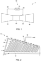
- FIG. 1 illustrates a turbine 1 according to one embodiment.
- the turbine 1 includes a compressor 10 to compress a fluid, such as air, water, steam, or another gas.
- the fluid is air.
- the compressor 10 includes a rotor 11 surrounded by a casing 15.
- the rotor 11 includes a shaft 12 and blades 13 protruding from the shaft 12.
- Stators, or vanes, 14 protrude from the casing 15.
- air is input to the compressor 10 as illustrated by the reference letter I.
- a flow of air is regulated by an air intake device 17.
- the air intake device 17 is a fan.
- the air intake device 17 includes adjustable nozzles or guide vanes.
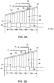
- the air is compressed by accelerating the air with the blades 13 and then by diffusing the air with the vanes 14.
- the blades 13 surround the shaft 12 in an annular fashion, and the vanes 14 line the inside of the casing 15 in an annular fashion.
- Each group of a set of blades 13 and a set of vanes 14 immediately downstream from the blades 13 comprises a stage, as indicated by the reference numerals S1-S11.
- FIG. 2 illustrates a compressor 10 having only eleven stages
- alternative embodiments include numbers of stages that vary according to desired design specifications.
- compressors of different embodiments include between 10 and 20 stages, and according to some embodiments, the stages are divided into low pressure stages and high pressure stages.
- the turbine 1 further includes a combustion chamber 20 to heat the air from the compressor 10.
- fuel is supplied to the combustion chamber 20 and ignited as the air passes through the combustion chamber 20.
- the turbine 1 further includes a turbine section 30 to convert the energy of the heated air to mechanical work and an exhaust section 40 to expel the air from the turbine 1.
- turbine is used in the art to describe both an entire device including a compressor, combustion chamber, and turbine section, as well as to describe just the turbine section.
- turbine section is used for clarity to describe the portion of the turbine 1 following the combustion chamber 20 to distinguish this portion of the turbine 1 from the description of the entire apparatus.
- the turbine section 30 includes a rotor 31 having a shaft 32 and buckets 33.
- the buckets 33 rotate about a rotation axis of the shaft 32 when the heated air is exerted on the buckets 33 from the combustion chamber 20, turning the shaft 32.
- the shaft 32 is the same as the shaft 12 of FIG. 2 .
- at least one stage TS1, TS2, and TS3 of the turbine section 30 is connected to a shaft that is different than the shaft 12 of FIG. 2 .
- the buckets 33 of the stages TS1 and TS2 are connected to the shaft 12 of FIG. 2
- the buckets 33 of the stage TS3 are connected to a separate shaft 32.
- the turbine section 30 includes nozzles 34 to direct the air onto the buckets 33 at predetermined angles.
- the nozzles 34 are comprised of stationary vanes, or airfoils, 35, an inner airfoil support 36, and the casing 37. According to alternative embodiments, an outer airfoil support is provided and attached to the casing 37.
- the buckets 33 generate a rotation force on the shaft 32.
- One or more devices are connected to the shaft to be driven by the shaft, such as a generator to generate electrical energy.
- the nozzles 34 and buckets 33 are arranged annularly about the shaft 32.
- Each group of an annular group of nozzles 34 and a following annular group of buckets 33 is a stage of the turbine section 30.
- the turbine section 30 includes any number of stages, including two stages, or any number greater than three stages.
- the turbine 1 of the present embodiment includes a bypass circuit 50 connected between the compressor 10 and the turbine section 30.
- the bypass circuit 50 includes a conduit 52 to transmit compressed air from the compressor 10, a valve 51 to control the transmission of the air between the compressor 10 and the turbine section 30, and a conduit 53 to transmit the air from the valve 51 to the turbine section 30.
- the air that is transferred from the compressor 10 to the turbine section 30 via the bypass circuit 50 is a bypass flow F.
- the air is removed from the compressor 10 via an outlet 16 in the sixth stage S6 of the compressor 10.
- the air is transferred from the compressor 10 at any stage, or from a plurality of stages, between the third stage S3 and the eleventh stage S11.
- the air input to the compressor 10 is increased by 10 to 20% relative to a conventional part-load input, and 10 to 20% of the compressed air is transmitted from the compressor 10 to the turbine section 30 via the bypass circuit 50.
- the air input to the compressor 10 is increased by 20% and 15% of the compressed air is transmitted from the compressor 10 to the turbine section 30 via the bypass circuit 50.
- the bypass flow F from the bypass circuit 50 is transmitted from the conduit 53 to an inlet 39 located at the last stage TS3 of the turbine section 30.
- the bypass flow F is then injected directly to the buckets 33 of the last stage TS3 to increases stage pressure ratio, resulting in additional output and improved efficiency.
- Increased pressure ratio in the last stage corrects the diffuser inlet tangential radial flow angles closer to design point, which avoids flow separation on the strut and hub walls. Correcting the diffuser inlet flow angles improves diffuser ideal and actual pressure recovery, resulting in additional output and improved efficiency.
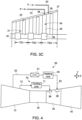
- FIG. 3A illustrates an example of a turbine section 30 in which the bypass flow F is injected at a location corresponding to the airfoils 35 of the last stage TS3.
- the bypass flow F is injected into the turbine section 30 prior to the airfoils 35 of the last stage TS3 in the length direction Z, as illustrated in FIG. 3B , or between the airfoils 35 and buckets 33 of the last stage TS3 in the length direction Z, as illustrated in FIG. 3C .
- the terms "at the last stage” and “to the last stage” include any location between the buckets 33 of the second-to-the-last stage TS2 and the buckets 33 of the last stage TS3 in the length direction Z, as illustrated in FIGS. 3A to 3C , respectively.
- FIG. 4 illustrates an embodiment in which the turbine 1 includes a cooling circuit 70.
- the cooling circuit 70 includes a cooling unit 71, a conduit 72 to transmit air between the compressor 10 and the cooling unit 71, and a conduit 73 to transmit air from the cooling unit 71 to the turbine section 30.
- the cooling unit 71 according to the present embodiment is piping to transmit air directly from the conduit 72 to the conduit 73. Since the air from the compressor 10 is cooler than the heated air in the turbine section 30, the air from the compressor 10 cools components of the turbine section 30.
- the cooling unit 71 includes a refrigerant or other cooling solution or structure to further cool the air from the compressor 10.
- there is no conduit 72 and instead, the cooling air is supplied to the cooling unit 71 from a source external to the turbine 1.
- the cooling circuit 70 transmits air to only a predetermined number of first stages of the turbine section 30, but does not transmit air to a predetermined number of last stages of the turbine section 30.
- the cooling circuit 70 transmits air to only stages TS1 and TS2, but not to TS3 of the turbine section 30.
- the cooling circuit 70 supplies air to the turbine section 30 via an inlet 38 and the bypass circuit 50 supplies air to the turbine section via an inlet 39 separate from the inlet 38.
- the inlets 38 and 39 are illustrated as being at separate locations in the length direction Z, and on a same side of the turbine section 30 in the height direction Y for purposes of clarity in description. However, in alternative embodiments, the inlets 38 and 39 are located at different positions around a circumference of the turbine section 30, including adjacent to each other in the length direction Z and apart from each other in the height direction Y.
- the bypass circuit 50 includes a heating unit 54 to heat the bypass flow F prior to transmitting the bypass flow F to the turbine section 30. Heating the bypass flow maintains a high energy level of the air that contacts the buckets 33 of the turbine section 30 to maintain a high operating efficiency of the turbine 1.
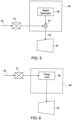
- FIGS. 5 to 7 provide examples of types of heating units 54.
- FIG. 5 illustrates a heating unit 54 including a steam generator 55 and a junction 57. Steam from the steam generator 55 is added to the bypass flow F from the compressor 10 to heat the bypass flow F, and the bypass flow F including the steam is provided to the turbine section 30.
- FIG. 6 illustrates a heating unit 54 including a firing unit 58.
- the bypass flow F passes through the firing unit 58 and is heated by the firing unit 58 before being transmitted to the turbine section 30.
- the firing unit 58 includes a combustion chamber in which fuel is ignited to heat the bypass flow F.
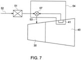
- FIG. 7 illustrates a heating unit 54 including an outlet 41 from the exhaust section 40, a junction 57, and conduit 59 from the outlet 41 to the junction 57.
- the exhaust section 40 outputs heated air from the turbine 1, and the outlet 41 transmits a portion of the heated air of the exhaust section 40 to the bypass flow F to heat the bypass flow F, or combines the heated air of the exhaust section 40 with the bypass flow F, before the bypass flow is transmitted to the turbine section 30.
- FIG. 8 illustrates a plan view of a portion of an annular group of airfoils 35 of the turbine section 30.
- the annular group of airfoils 35 makes up nozzles 34.
- each nozzle 34 comprises two adjacent airfoils 35, an inner airfoil support 36 and an outer airfoil support 62.
- the adjacent airfoils 35, inner airfoil support 36, and outer airfoil support 62 define a nozzle opening 61 through which air is directed to buckets 33.
- a size of the opening relative to the airfoils 35 is exaggerated in FIG. 8 for purposes of clarity in describing the structure of the present embodiment.
- the outer airfoil support 62 comprises a plurality of segments 63. Each segment corresponds to a separate airfoil 35, and the segments 63 are connected to the casing 37 to secure the airfoils 35. According to alternative embodiments, the airfoils 35 are connected directly to the casing 37 and the structures described in the segments 63 of FIG. 8 are provided in the casing 37.
- Each segment 63 includes a cavity 64 to receive the purge flow P and the bypass flow F, to transmit the purge flow P into the airfoil 35 via an inlet 67 and to transmit the bypass flow F into the nozzle opening 61 via an inlet 68.
- the cavity 64 is divided into separate sections by a divider 65 which extends from upper and lower inner walls of the segment 63.
- the divider 65 includes an opening 66 to allow some air mixing between the bypass flow F and the purge flow P.
- the opening 66 has a circumference less than a circumference of the cavity 64.
- Each airfoil 35 includes a purge flow cavity 69 to receive the purge flow P, and to transmit the purge flow P to an outlet 81.
- the outlet 81 is at an opposite end of the airfoil 35 from the inlet 67 to allow the purge flow P to travel the length of the airfoil 35 to avoid hot gas entering into the rotor region, such as into a region corresponding to the inner airfoil support 36 and the shaft 12.
- each segment 63 and airfoil 35 are illustrated as having a cavity 64 and purge flow cavity 69, respectively, in FIG. 8 , for purposes of clarity in describing the present embodiment.
- each segment 63 and airfoil 35 of a stage includes similar features.
- stages TS1, TS2, and TS3 include the purge flow cavity 69 and others do not.
- each stage except the last stage TS3 includes airfoils 35 having the purge flow cavity 69, but the airfoils 35 of the last stage TS3 do not include the purge flow cavity 69.
- each stage TS1, TS2, and TS3 includes the airfoils 35 having the purge flow cavity 69.
- the purge flow P is transmitted through the airfoil 35 and the bypass flow F is transmitted directly to the buckets 33 via the opening 61.
- the bypass flow F does not enter the airfoil 35, and instead only the purge flow P enters the cavity 69 of the airfoil 35.
- some air from the bypass circuit 50 enters the cavity 69 of the airfoil 35 via the opening 66 of the cavity 64 in the segment 63, the flow of air that makes up the majority of the bypass flow F does not pass through the opening 66.
- the portion of air that passes through the opening 66 into the cavity 69 is no longer considered part of the bypass flow F in the present specification and claims.
- no opening 66 exists, and instead the divider 65 entirely separates the purge flow P from the bypass flow F.
- FIGS. 9 and 10 illustrate structures to introduce the purge flow P and bypass flow F into the turbine section 30 according to an alternative embodiment.
- the purge flow P passes through the inlets 38 and 67 into the purge flow cavity 69.
- the purge flow cavity 69 extends a length of the airfoil 35 and the purge flow P exits the airfoil 35 via an outlet 81.
- the bypass flow F passes through the inlets 39 and 68 into a bypass flow cavity 82.
- the bypass flow cavity 82 is connected to the bypass flow cavity 69 via openings 84.
- the bypass flow F is transmitted directly to the buckets 33 via openings 83.
- the purge flow P first transverses the length of the airfoil 35, while the bypass flow F enters the opening 61 via openings 83 in the airfoil 35 that face the opening 61. Consequently, the bypass flow F corrects an exit flow angle of air passing around the airfoil 35, while the purge flow P does not.
- the openings 84 in the airfoil 35 allow some mixing of air from the bypass flow F with air from the purge flow P, the small size of the openings relative to a size of the purge flow cavity 69 and the bypass flow cavity 82 results in only a small mixing of air. Consequently, the purge flow P and the bypass flow F remain separate in the purge flow cavity 69 and bypass flow cavity 82. According to alternative embodiments, no opening 84 exists, and the purge flow cavity 69 and the bypass flow cavity 82 are entirely separated within the airfoil 35.
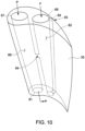
- FIG. 10 illustrates an airfoil 35 according to an embodiment of the present invention.
- the airfoil 35 is similar to that of FIG. 9 , except the opening 83 extends the length of the airfoil 35.
- FIG. 9 illustrates a plurality of openings 83 running the length of the airfoil 35
- FIG. 10 illustrates one opening 83 extending the length of the airfoil 35.
- a rim 85 of the airfoil 35 defines the opening 83 and directs the bypass flow F in a predetermined direction to correct a pressure ratio and exit flow angle of the air passing around the airfoil 35 towards the buckets 33.
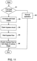
- FIG. 11 illustrates a method of controlling the turbine 1 during a part-load operation.
- a part-load is defined as a load less than 90% of the normal output of the turbine.
- the turbine 1 is designed to operate at a predetermined load, which is defined as a peak load or a base load.
- a predetermined load which is defined as a peak load or a base load.
- a part load is less than 60% of the base load, or less than 50% of the base load, respectively.
- the normal operation settings are implemented in operation 92.
- the air intake is set at 100%
- the combustion level is set at 100%
- the valve 51 to cause the bypass flow to bypass the combustion chamber 20 is closed.
- the method proceeds to operation 93.
- a predetermined part-load intake level is determined, and the predetermined intake level is increased by 20%.
- the intake level is increased by a level in the range from 15% to 25%.
- the valve 51 is opened, allowing the bypass flow F to bypass the combustion chamber 20 and to flow to the turbine section 30.
- 15% of the intake air is turned into the bypass flow F and transmitted via the bypass circuit 50 to the turbine section 30.
- the percentage of intake air that bypasses the combustion chamber 20 via the bypass circuit 50 is a percentage in the range from 10% to 20%, depending on the turbine load.
- bypass flow F is heated, and in operation 96, the heated bypass flow F is supplied to the turbine section 30.
- the bypass flow F is supplied to the last stage of the turbine section 30.
- a bypass flow F of air is generated in a turbine 1 operating at part-load.
- the bypass flow F is heated and injected into the turbine section 30 to correct the stage pressure ratio and exit flow angle of air in the turbine section 30 to improve efficiency of the turbine 1 during part-load operation.
Landscapes
- Engineering & Computer Science (AREA)
- Mechanical Engineering (AREA)
- General Engineering & Computer Science (AREA)
- Chemical & Material Sciences (AREA)
- Combustion & Propulsion (AREA)
- Physics & Mathematics (AREA)
- Fluid Mechanics (AREA)
- Control Of Turbines (AREA)
- Turbine Rotor Nozzle Sealing (AREA)
- Structures Of Non-Positive Displacement Pumps (AREA)
Applications Claiming Priority (1)
| Application Number | Priority Date | Filing Date | Title |
|---|---|---|---|
| US13/343,269 US9169782B2 (en) | 2012-01-04 | 2012-01-04 | Turbine to operate at part-load |
Publications (3)
| Publication Number | Publication Date |
|---|---|
| EP2613041A2 EP2613041A2 (en) | 2013-07-10 |
| EP2613041A3 EP2613041A3 (en) | 2017-07-05 |
| EP2613041B1 true EP2613041B1 (en) | 2024-07-31 |
Family
ID=47678500
Family Applications (1)
| Application Number | Title | Priority Date | Filing Date |
|---|---|---|---|
| EP12198711.9A Active EP2613041B1 (en) | 2012-01-04 | 2012-12-20 | Turbine to operate at part-load |
Country Status (5)
| Country | Link |
|---|---|
| US (1) | US9169782B2 (enExample) |
| EP (1) | EP2613041B1 (enExample) |
| JP (1) | JP6228360B2 (enExample) |
| CN (1) | CN103195584B (enExample) |
| RU (1) | RU2012158337A (enExample) |
Families Citing this family (9)
| Publication number | Priority date | Publication date | Assignee | Title |
|---|---|---|---|---|
| US9541008B2 (en) * | 2012-02-06 | 2017-01-10 | General Electric Company | Method and apparatus to control part-load performance of a turbine |
| US9534536B2 (en) * | 2013-07-02 | 2017-01-03 | General Electric Company | Turbine flow modulation for part load performance |
| JP6389613B2 (ja) | 2014-01-27 | 2018-09-12 | 三菱日立パワーシステムズ株式会社 | ガスタービン発電設備およびガスタービン冷却空気系統乾燥方法 |
| EP2957746B1 (en) * | 2014-06-17 | 2021-04-28 | Raytheon Technologies Corporation | High pressure turbine cooling |
| EP3112607B1 (en) * | 2015-07-02 | 2018-10-24 | Ansaldo Energia Switzerland AG | Gas turbine cool-down phase operation methods |
| US10641174B2 (en) * | 2017-01-18 | 2020-05-05 | General Electric Company | Rotor shaft cooling |
| US12078102B2 (en) | 2022-09-23 | 2024-09-03 | Rtx Corporation | Air recuperated engine with air reinjection |
| US12338776B1 (en) | 2023-12-22 | 2025-06-24 | Ge Infrastructure Technology Llc | Fluid injection system and method for mitigating rotating stall in turbine engine |
| US12428973B2 (en) | 2023-12-22 | 2025-09-30 | Ge Infrastructure Technology Llc | Mitigation of rotating stall in turbine exhaust section using segmented auxiliary struts |
Family Cites Families (19)
| Publication number | Priority date | Publication date | Assignee | Title |
|---|---|---|---|---|
| US3699681A (en) * | 1970-07-09 | 1972-10-24 | Bbc Sulzer Turbomaschinen | Load control for gas turbine plant |
| US4858428A (en) * | 1986-04-24 | 1989-08-22 | Paul Marius A | Advanced integrated propulsion system with total optimized cycle for gas turbines |
| JPH0518270A (ja) * | 1991-07-08 | 1993-01-26 | Mitsubishi Heavy Ind Ltd | エンジンの制御方法及び装置 |
| CA2263508C (en) * | 1997-06-19 | 2003-08-19 | Mitsubishi Heavy Industries, Ltd. | Sealing device for gas turbine stator blades |
| JP2000230404A (ja) * | 1999-02-09 | 2000-08-22 | Mitsubishi Heavy Ind Ltd | ガスタービン静翼 |
| US6183192B1 (en) * | 1999-03-22 | 2001-02-06 | General Electric Company | Durable turbine nozzle |
| US6393825B1 (en) | 2000-01-25 | 2002-05-28 | General Electric Company | System for pressure modulation of turbine sidewall cavities |
| JP3849473B2 (ja) * | 2001-08-29 | 2006-11-22 | 株式会社日立製作所 | ガスタービンの高温部冷却方法 |
| US6550253B2 (en) * | 2001-09-12 | 2003-04-22 | General Electric Company | Apparatus and methods for controlling flow in turbomachinery |
| US7008185B2 (en) * | 2003-02-27 | 2006-03-07 | General Electric Company | Gas turbine engine turbine nozzle bifurcated impingement baffle |
| US8495883B2 (en) | 2007-04-05 | 2013-07-30 | Siemens Energy, Inc. | Cooling of turbine components using combustor shell air |
| US8015826B2 (en) * | 2007-04-05 | 2011-09-13 | Siemens Energy, Inc. | Engine brake for part load CO reduction |
| FR2919897B1 (fr) * | 2007-08-08 | 2014-08-22 | Snecma | Secteur de distributeur de turbine |
| US20090056342A1 (en) | 2007-09-04 | 2009-03-05 | General Electric Company | Methods and Systems for Gas Turbine Part-Load Operating Conditions |
| US8240153B2 (en) * | 2008-05-14 | 2012-08-14 | General Electric Company | Method and system for controlling a set point for extracting air from a compressor to provide turbine cooling air in a gas turbine |
| US8157515B2 (en) * | 2008-08-01 | 2012-04-17 | General Electric Company | Split doublet power nozzle and related method |
| JP5297114B2 (ja) * | 2008-08-06 | 2013-09-25 | 三菱重工業株式会社 | ガスタービン |
| US8281565B2 (en) * | 2009-10-16 | 2012-10-09 | General Electric Company | Reheat gas turbine |
| US8973373B2 (en) * | 2011-10-31 | 2015-03-10 | General Electric Company | Active clearance control system and method for gas turbine |
-
2012
- 2012-01-04 US US13/343,269 patent/US9169782B2/en active Active
- 2012-12-20 EP EP12198711.9A patent/EP2613041B1/en active Active
- 2012-12-20 JP JP2012277543A patent/JP6228360B2/ja active Active
- 2012-12-27 RU RU2012158337/06A patent/RU2012158337A/ru not_active Application Discontinuation
-
2013
- 2013-01-04 CN CN201310001290.7A patent/CN103195584B/zh active Active
Also Published As
| Publication number | Publication date |
|---|---|
| CN103195584B (zh) | 2016-08-03 |
| JP6228360B2 (ja) | 2017-11-08 |
| US9169782B2 (en) | 2015-10-27 |
| EP2613041A2 (en) | 2013-07-10 |
| JP2013139781A (ja) | 2013-07-18 |
| US20130167551A1 (en) | 2013-07-04 |
| CN103195584A (zh) | 2013-07-10 |
| RU2012158337A (ru) | 2014-07-10 |
| EP2613041A3 (en) | 2017-07-05 |
Similar Documents
| Publication | Publication Date | Title |
|---|---|---|
| EP2613041B1 (en) | Turbine to operate at part-load | |
| US10619564B2 (en) | Gas turbine and component-temperature adjustment method therefor | |
| JP7086516B2 (ja) | ガスタービン出力増大システム | |
| JP2007315398A (ja) | 不足周波数運転時における抽気の使用によるガスタービン運転の方法 | |
| RU2575837C9 (ru) | Устройство и способ для уменьшения массового расхода воздуха для сгорания с низкими выбросами в расширенном диапазоне для одновальных газовых турбин | |
| US20130084162A1 (en) | Gas Turbine | |
| JP2016176469A (ja) | 過剰空気流を生成する圧縮機を有する発電システム | |
| KR20180086386A (ko) | 복합 사이클 발전 플랜트를 리트로피팅하는 장치 및 프로세스 | |
| CN103459804B (zh) | 用于冷却涡轮机级的方法和具有冷却的涡轮机级的燃气轮机 | |
| CN105849370B (zh) | 高压力比双转子的工业燃气涡轮发动机 | |
| JP2016176466A (ja) | 余剰空気を作り出す圧縮機および補助圧縮機を備える発電システム | |
| KR20160076474A (ko) | 엔진 및 상기 엔진을 작동시키기 위한 방법 | |
| JP2016176468A (ja) | タービン排気ガス質量流を増加させるため過剰空気流を生成する圧縮機及びターボエキスパンダを有する発電システム | |
| EP3070293A1 (en) | Power generation system having compressor creating excess air flow and turbo-expander for cooling inlet air | |
| JP2011516780A (ja) | タービン装置 | |
| EP2623751B1 (en) | Method and apparatus to control part-load performance of a turbine | |
| KR101619753B1 (ko) | 유체-유동 장치용 축류 압축기 | |
| JP2016176477A (ja) | 余剰空気流を生じる圧縮機とそれのための冷却流体注入とを有する発電システム | |
| US10858996B2 (en) | Gas turbine startup method and device | |
| JP2013076388A (ja) | 一軸型複合サイクル発電プラント及びその運転方法 | |
| CN109812340B (zh) | 包括外部冷却系统的燃气轮机及其冷却方法 | |
| US9719418B2 (en) | Turbomachine inlet bleed heating assembly | |
| CN105386876A (zh) | 联合循环发电设备 | |
| JP5650674B2 (ja) | ガスタービンの間隙制御装置、間隙制御方法及び間隙制御装置を備えたガスタービン | |
| JP6783043B2 (ja) | 複合サイクル発電プラントの熱エネルギー節減方法 |
Legal Events
| Date | Code | Title | Description |
|---|---|---|---|
| PUAI | Public reference made under article 153(3) epc to a published international application that has entered the european phase |
Free format text: ORIGINAL CODE: 0009012 |
|
| AK | Designated contracting states |
Kind code of ref document: A2 Designated state(s): AL AT BE BG CH CY CZ DE DK EE ES FI FR GB GR HR HU IE IS IT LI LT LU LV MC MK MT NL NO PL PT RO RS SE SI SK SM TR |
|
| AX | Request for extension of the european patent |
Extension state: BA ME |
|
| PUAL | Search report despatched |
Free format text: ORIGINAL CODE: 0009013 |
|
| AK | Designated contracting states |
Kind code of ref document: A3 Designated state(s): AL AT BE BG CH CY CZ DE DK EE ES FI FR GB GR HR HU IE IS IT LI LT LU LV MC MK MT NL NO PL PT RO RS SE SI SK SM TR |
|
| AX | Request for extension of the european patent |
Extension state: BA ME |
|
| RIC1 | Information provided on ipc code assigned before grant |
Ipc: F01D 5/18 20060101ALI20170601BHEP Ipc: F02C 9/18 20060101AFI20170601BHEP Ipc: F01D 25/08 20060101ALI20170601BHEP Ipc: F02C 7/14 20060101ALI20170601BHEP Ipc: F01D 9/04 20060101ALI20170601BHEP Ipc: F02C 1/04 20060101ALI20170601BHEP Ipc: F01D 9/06 20060101ALI20170601BHEP |
|
| STAA | Information on the status of an ep patent application or granted ep patent |
Free format text: STATUS: REQUEST FOR EXAMINATION WAS MADE |
|
| 17P | Request for examination filed |
Effective date: 20180105 |
|
| RBV | Designated contracting states (corrected) |
Designated state(s): AL AT BE BG CH CY CZ DE DK EE ES FI FR GB GR HR HU IE IS IT LI LT LU LV MC MK MT NL NO PL PT RO RS SE SI SK SM TR |
|
| STAA | Information on the status of an ep patent application or granted ep patent |
Free format text: STATUS: EXAMINATION IS IN PROGRESS |
|
| 17Q | First examination report despatched |
Effective date: 20190617 |
|
| RAP1 | Party data changed (applicant data changed or rights of an application transferred) |
Owner name: GENERAL ELECTRIC TECHNOLOGY GMBH |
|
| GRAP | Despatch of communication of intention to grant a patent |
Free format text: ORIGINAL CODE: EPIDOSNIGR1 |
|
| STAA | Information on the status of an ep patent application or granted ep patent |
Free format text: STATUS: GRANT OF PATENT IS INTENDED |
|
| INTG | Intention to grant announced |
Effective date: 20240119 |
|
| GRAS | Grant fee paid |
Free format text: ORIGINAL CODE: EPIDOSNIGR3 |
|
| GRAA | (expected) grant |
Free format text: ORIGINAL CODE: 0009210 |
|
| STAA | Information on the status of an ep patent application or granted ep patent |
Free format text: STATUS: THE PATENT HAS BEEN GRANTED |
|
| AK | Designated contracting states |
Kind code of ref document: B1 Designated state(s): AL AT BE BG CH CY CZ DE DK EE ES FI FR GB GR HR HU IE IS IT LI LT LU LV MC MK MT NL NO PL PT RO RS SE SI SK SM TR |
|
| REG | Reference to a national code |
Ref country code: CH Ref legal event code: EP Ref country code: GB Ref legal event code: FG4D |
|
| REG | Reference to a national code |
Ref country code: DE Ref legal event code: R096 Ref document number: 602012080967 Country of ref document: DE |
|
| REG | Reference to a national code |
Ref country code: IE Ref legal event code: FG4D |
|
| REG | Reference to a national code |
Ref country code: LT Ref legal event code: MG9D |
|
| REG | Reference to a national code |
Ref country code: NL Ref legal event code: MP Effective date: 20240731 |
|
| PG25 | Lapsed in a contracting state [announced via postgrant information from national office to epo] |
Ref country code: PT Free format text: LAPSE BECAUSE OF FAILURE TO SUBMIT A TRANSLATION OF THE DESCRIPTION OR TO PAY THE FEE WITHIN THE PRESCRIBED TIME-LIMIT Effective date: 20241202 |
|
| REG | Reference to a national code |
Ref country code: AT Ref legal event code: MK05 Ref document number: 1708654 Country of ref document: AT Kind code of ref document: T Effective date: 20240731 |
|
| PG25 | Lapsed in a contracting state [announced via postgrant information from national office to epo] |
Ref country code: PT Free format text: LAPSE BECAUSE OF FAILURE TO SUBMIT A TRANSLATION OF THE DESCRIPTION OR TO PAY THE FEE WITHIN THE PRESCRIBED TIME-LIMIT Effective date: 20241202 |
|
| PGFP | Annual fee paid to national office [announced via postgrant information from national office to epo] |
Ref country code: DE Payment date: 20241121 Year of fee payment: 13 |
|
| PG25 | Lapsed in a contracting state [announced via postgrant information from national office to epo] |
Ref country code: NO Free format text: LAPSE BECAUSE OF FAILURE TO SUBMIT A TRANSLATION OF THE DESCRIPTION OR TO PAY THE FEE WITHIN THE PRESCRIBED TIME-LIMIT Effective date: 20241031 |
|
| PG25 | Lapsed in a contracting state [announced via postgrant information from national office to epo] |
Ref country code: PL Free format text: LAPSE BECAUSE OF FAILURE TO SUBMIT A TRANSLATION OF THE DESCRIPTION OR TO PAY THE FEE WITHIN THE PRESCRIBED TIME-LIMIT Effective date: 20240731 Ref country code: FI Free format text: LAPSE BECAUSE OF FAILURE TO SUBMIT A TRANSLATION OF THE DESCRIPTION OR TO PAY THE FEE WITHIN THE PRESCRIBED TIME-LIMIT Effective date: 20240731 Ref country code: NL Free format text: LAPSE BECAUSE OF FAILURE TO SUBMIT A TRANSLATION OF THE DESCRIPTION OR TO PAY THE FEE WITHIN THE PRESCRIBED TIME-LIMIT Effective date: 20240731 Ref country code: GR Free format text: LAPSE BECAUSE OF FAILURE TO SUBMIT A TRANSLATION OF THE DESCRIPTION OR TO PAY THE FEE WITHIN THE PRESCRIBED TIME-LIMIT Effective date: 20241101 |
|
| PG25 | Lapsed in a contracting state [announced via postgrant information from national office to epo] |
Ref country code: BG Free format text: LAPSE BECAUSE OF FAILURE TO SUBMIT A TRANSLATION OF THE DESCRIPTION OR TO PAY THE FEE WITHIN THE PRESCRIBED TIME-LIMIT Effective date: 20240731 |
|
| PG25 | Lapsed in a contracting state [announced via postgrant information from national office to epo] |
Ref country code: LV Free format text: LAPSE BECAUSE OF FAILURE TO SUBMIT A TRANSLATION OF THE DESCRIPTION OR TO PAY THE FEE WITHIN THE PRESCRIBED TIME-LIMIT Effective date: 20240731 |
|
| PG25 | Lapsed in a contracting state [announced via postgrant information from national office to epo] |
Ref country code: AT Free format text: LAPSE BECAUSE OF FAILURE TO SUBMIT A TRANSLATION OF THE DESCRIPTION OR TO PAY THE FEE WITHIN THE PRESCRIBED TIME-LIMIT Effective date: 20240731 Ref country code: IS Free format text: LAPSE BECAUSE OF FAILURE TO SUBMIT A TRANSLATION OF THE DESCRIPTION OR TO PAY THE FEE WITHIN THE PRESCRIBED TIME-LIMIT Effective date: 20241130 |
|
| PG25 | Lapsed in a contracting state [announced via postgrant information from national office to epo] |
Ref country code: HR Free format text: LAPSE BECAUSE OF FAILURE TO SUBMIT A TRANSLATION OF THE DESCRIPTION OR TO PAY THE FEE WITHIN THE PRESCRIBED TIME-LIMIT Effective date: 20240731 |
|
| PG25 | Lapsed in a contracting state [announced via postgrant information from national office to epo] |
Ref country code: ES Free format text: LAPSE BECAUSE OF FAILURE TO SUBMIT A TRANSLATION OF THE DESCRIPTION OR TO PAY THE FEE WITHIN THE PRESCRIBED TIME-LIMIT Effective date: 20240731 Ref country code: RS Free format text: LAPSE BECAUSE OF FAILURE TO SUBMIT A TRANSLATION OF THE DESCRIPTION OR TO PAY THE FEE WITHIN THE PRESCRIBED TIME-LIMIT Effective date: 20241031 |
|
| PGFP | Annual fee paid to national office [announced via postgrant information from national office to epo] |
Ref country code: IT Payment date: 20241121 Year of fee payment: 13 |
|
| PG25 | Lapsed in a contracting state [announced via postgrant information from national office to epo] |
Ref country code: RS Free format text: LAPSE BECAUSE OF FAILURE TO SUBMIT A TRANSLATION OF THE DESCRIPTION OR TO PAY THE FEE WITHIN THE PRESCRIBED TIME-LIMIT Effective date: 20241031 Ref country code: PL Free format text: LAPSE BECAUSE OF FAILURE TO SUBMIT A TRANSLATION OF THE DESCRIPTION OR TO PAY THE FEE WITHIN THE PRESCRIBED TIME-LIMIT Effective date: 20240731 Ref country code: NO Free format text: LAPSE BECAUSE OF FAILURE TO SUBMIT A TRANSLATION OF THE DESCRIPTION OR TO PAY THE FEE WITHIN THE PRESCRIBED TIME-LIMIT Effective date: 20241031 Ref country code: NL Free format text: LAPSE BECAUSE OF FAILURE TO SUBMIT A TRANSLATION OF THE DESCRIPTION OR TO PAY THE FEE WITHIN THE PRESCRIBED TIME-LIMIT Effective date: 20240731 Ref country code: LV Free format text: LAPSE BECAUSE OF FAILURE TO SUBMIT A TRANSLATION OF THE DESCRIPTION OR TO PAY THE FEE WITHIN THE PRESCRIBED TIME-LIMIT Effective date: 20240731 Ref country code: IS Free format text: LAPSE BECAUSE OF FAILURE TO SUBMIT A TRANSLATION OF THE DESCRIPTION OR TO PAY THE FEE WITHIN THE PRESCRIBED TIME-LIMIT Effective date: 20241130 Ref country code: HR Free format text: LAPSE BECAUSE OF FAILURE TO SUBMIT A TRANSLATION OF THE DESCRIPTION OR TO PAY THE FEE WITHIN THE PRESCRIBED TIME-LIMIT Effective date: 20240731 Ref country code: GR Free format text: LAPSE BECAUSE OF FAILURE TO SUBMIT A TRANSLATION OF THE DESCRIPTION OR TO PAY THE FEE WITHIN THE PRESCRIBED TIME-LIMIT Effective date: 20241101 Ref country code: FI Free format text: LAPSE BECAUSE OF FAILURE TO SUBMIT A TRANSLATION OF THE DESCRIPTION OR TO PAY THE FEE WITHIN THE PRESCRIBED TIME-LIMIT Effective date: 20240731 Ref country code: ES Free format text: LAPSE BECAUSE OF FAILURE TO SUBMIT A TRANSLATION OF THE DESCRIPTION OR TO PAY THE FEE WITHIN THE PRESCRIBED TIME-LIMIT Effective date: 20240731 Ref country code: BG Free format text: LAPSE BECAUSE OF FAILURE TO SUBMIT A TRANSLATION OF THE DESCRIPTION OR TO PAY THE FEE WITHIN THE PRESCRIBED TIME-LIMIT Effective date: 20240731 Ref country code: AT Free format text: LAPSE BECAUSE OF FAILURE TO SUBMIT A TRANSLATION OF THE DESCRIPTION OR TO PAY THE FEE WITHIN THE PRESCRIBED TIME-LIMIT Effective date: 20240731 |
|
| PG25 | Lapsed in a contracting state [announced via postgrant information from national office to epo] |
Ref country code: SM Free format text: LAPSE BECAUSE OF FAILURE TO SUBMIT A TRANSLATION OF THE DESCRIPTION OR TO PAY THE FEE WITHIN THE PRESCRIBED TIME-LIMIT Effective date: 20240731 Ref country code: DK Free format text: LAPSE BECAUSE OF FAILURE TO SUBMIT A TRANSLATION OF THE DESCRIPTION OR TO PAY THE FEE WITHIN THE PRESCRIBED TIME-LIMIT Effective date: 20240731 Ref country code: RO Free format text: LAPSE BECAUSE OF FAILURE TO SUBMIT A TRANSLATION OF THE DESCRIPTION OR TO PAY THE FEE WITHIN THE PRESCRIBED TIME-LIMIT Effective date: 20240731 |
|
| PG25 | Lapsed in a contracting state [announced via postgrant information from national office to epo] |
Ref country code: EE Free format text: LAPSE BECAUSE OF FAILURE TO SUBMIT A TRANSLATION OF THE DESCRIPTION OR TO PAY THE FEE WITHIN THE PRESCRIBED TIME-LIMIT Effective date: 20240731 |
|
| PG25 | Lapsed in a contracting state [announced via postgrant information from national office to epo] |
Ref country code: CZ Free format text: LAPSE BECAUSE OF FAILURE TO SUBMIT A TRANSLATION OF THE DESCRIPTION OR TO PAY THE FEE WITHIN THE PRESCRIBED TIME-LIMIT Effective date: 20240731 |
|
| PG25 | Lapsed in a contracting state [announced via postgrant information from national office to epo] |
Ref country code: SK Free format text: LAPSE BECAUSE OF FAILURE TO SUBMIT A TRANSLATION OF THE DESCRIPTION OR TO PAY THE FEE WITHIN THE PRESCRIBED TIME-LIMIT Effective date: 20240731 |
|
| REG | Reference to a national code |
Ref country code: DE Ref legal event code: R097 Ref document number: 602012080967 Country of ref document: DE |
|
| PLBE | No opposition filed within time limit |
Free format text: ORIGINAL CODE: 0009261 |
|
| STAA | Information on the status of an ep patent application or granted ep patent |
Free format text: STATUS: NO OPPOSITION FILED WITHIN TIME LIMIT |
|
| PG25 | Lapsed in a contracting state [announced via postgrant information from national office to epo] |
Ref country code: MC Free format text: LAPSE BECAUSE OF FAILURE TO SUBMIT A TRANSLATION OF THE DESCRIPTION OR TO PAY THE FEE WITHIN THE PRESCRIBED TIME-LIMIT Effective date: 20240731 |
|
| 26N | No opposition filed |
Effective date: 20250501 |
|
| REG | Reference to a national code |
Ref country code: CH Ref legal event code: PL |
|
| PG25 | Lapsed in a contracting state [announced via postgrant information from national office to epo] |
Ref country code: LU Free format text: LAPSE BECAUSE OF NON-PAYMENT OF DUE FEES Effective date: 20241220 |
|
| GBPC | Gb: european patent ceased through non-payment of renewal fee |
Effective date: 20241220 |
|
| PG25 | Lapsed in a contracting state [announced via postgrant information from national office to epo] |
Ref country code: SE Free format text: LAPSE BECAUSE OF FAILURE TO SUBMIT A TRANSLATION OF THE DESCRIPTION OR TO PAY THE FEE WITHIN THE PRESCRIBED TIME-LIMIT Effective date: 20240731 |
|
| REG | Reference to a national code |
Ref country code: BE Ref legal event code: MM Effective date: 20241231 |
|
| PG25 | Lapsed in a contracting state [announced via postgrant information from national office to epo] |
Ref country code: BE Free format text: LAPSE BECAUSE OF NON-PAYMENT OF DUE FEES Effective date: 20241231 Ref country code: GB Free format text: LAPSE BECAUSE OF NON-PAYMENT OF DUE FEES Effective date: 20241220 |
|
| PG25 | Lapsed in a contracting state [announced via postgrant information from national office to epo] |
Ref country code: FR Free format text: LAPSE BECAUSE OF NON-PAYMENT OF DUE FEES Effective date: 20241231 |
|
| PG25 | Lapsed in a contracting state [announced via postgrant information from national office to epo] |
Ref country code: CH Free format text: LAPSE BECAUSE OF NON-PAYMENT OF DUE FEES Effective date: 20241231 |
|
| PG25 | Lapsed in a contracting state [announced via postgrant information from national office to epo] |
Ref country code: IE Free format text: LAPSE BECAUSE OF NON-PAYMENT OF DUE FEES Effective date: 20241220 |