EP2613000B1 - Système de rétention axiale de segments rotatifs d'une turbine et procedé associé - Google Patents
Système de rétention axiale de segments rotatifs d'une turbine et procedé associé Download PDFInfo
- Publication number
- EP2613000B1 EP2613000B1 EP12199013.9A EP12199013A EP2613000B1 EP 2613000 B1 EP2613000 B1 EP 2613000B1 EP 12199013 A EP12199013 A EP 12199013A EP 2613000 B1 EP2613000 B1 EP 2613000B1
- Authority
- EP
- European Patent Office
- Prior art keywords
- slot
- axial
- mating
- rotor
- pin
- Prior art date
- Legal status (The legal status is an assumption and is not a legal conclusion. Google has not performed a legal analysis and makes no representation as to the accuracy of the status listed.)
- Active
Links
- 230000014759 maintenance of location Effects 0.000 title claims description 68
- 238000000034 method Methods 0.000 title claims description 5
- 230000013011 mating Effects 0.000 claims description 111
- 238000003780 insertion Methods 0.000 claims description 12
- 230000037431 insertion Effects 0.000 claims description 12
- 239000007789 gas Substances 0.000 description 20
- 239000000567 combustion gas Substances 0.000 description 6
- 239000000446 fuel Substances 0.000 description 3
- 238000013461 design Methods 0.000 description 2
- 238000010586 diagram Methods 0.000 description 2
- 238000004519 manufacturing process Methods 0.000 description 2
- 239000000203 mixture Substances 0.000 description 2
- 230000009977 dual effect Effects 0.000 description 1
- 230000000694 effects Effects 0.000 description 1
- 230000006870 function Effects 0.000 description 1
- ZZUFCTLCJUWOSV-UHFFFAOYSA-N furosemide Chemical compound C1=C(Cl)C(S(=O)(=O)N)=CC(C(O)=O)=C1NCC1=CC=CO1 ZZUFCTLCJUWOSV-UHFFFAOYSA-N 0.000 description 1
- 238000009434 installation Methods 0.000 description 1
- 230000003137 locomotive effect Effects 0.000 description 1
- 238000010248 power generation Methods 0.000 description 1
Images


Classifications
-
- F—MECHANICAL ENGINEERING; LIGHTING; HEATING; WEAPONS; BLASTING
- F01—MACHINES OR ENGINES IN GENERAL; ENGINE PLANTS IN GENERAL; STEAM ENGINES
- F01D—NON-POSITIVE DISPLACEMENT MACHINES OR ENGINES, e.g. STEAM TURBINES
- F01D5/00—Blades; Blade-carrying members; Heating, heat-insulating, cooling or antivibration means on the blades or the members
- F01D5/12—Blades
- F01D5/22—Blade-to-blade connections, e.g. for damping vibrations
-
- F—MECHANICAL ENGINEERING; LIGHTING; HEATING; WEAPONS; BLASTING
- F01—MACHINES OR ENGINES IN GENERAL; ENGINE PLANTS IN GENERAL; STEAM ENGINES
- F01D—NON-POSITIVE DISPLACEMENT MACHINES OR ENGINES, e.g. STEAM TURBINES
- F01D5/00—Blades; Blade-carrying members; Heating, heat-insulating, cooling or antivibration means on the blades or the members
- F01D5/30—Fixing blades to rotors; Blade roots ; Blade spacers
- F01D5/3053—Fixing blades to rotors; Blade roots ; Blade spacers by means of pins
-
- F—MECHANICAL ENGINEERING; LIGHTING; HEATING; WEAPONS; BLASTING
- F01—MACHINES OR ENGINES IN GENERAL; ENGINE PLANTS IN GENERAL; STEAM ENGINES
- F01D—NON-POSITIVE DISPLACEMENT MACHINES OR ENGINES, e.g. STEAM TURBINES
- F01D5/00—Blades; Blade-carrying members; Heating, heat-insulating, cooling or antivibration means on the blades or the members
- F01D5/30—Fixing blades to rotors; Blade roots ; Blade spacers
- F01D5/32—Locking, e.g. by final locking blades or keys
-
- F—MECHANICAL ENGINEERING; LIGHTING; HEATING; WEAPONS; BLASTING
- F01—MACHINES OR ENGINES IN GENERAL; ENGINE PLANTS IN GENERAL; STEAM ENGINES
- F01D—NON-POSITIVE DISPLACEMENT MACHINES OR ENGINES, e.g. STEAM TURBINES
- F01D5/00—Blades; Blade-carrying members; Heating, heat-insulating, cooling or antivibration means on the blades or the members
- F01D5/30—Fixing blades to rotors; Blade roots ; Blade spacers
- F01D5/3007—Fixing blades to rotors; Blade roots ; Blade spacers of axial insertion type
-
- Y—GENERAL TAGGING OF NEW TECHNOLOGICAL DEVELOPMENTS; GENERAL TAGGING OF CROSS-SECTIONAL TECHNOLOGIES SPANNING OVER SEVERAL SECTIONS OF THE IPC; TECHNICAL SUBJECTS COVERED BY FORMER USPC CROSS-REFERENCE ART COLLECTIONS [XRACs] AND DIGESTS
- Y10—TECHNICAL SUBJECTS COVERED BY FORMER USPC
- Y10T—TECHNICAL SUBJECTS COVERED BY FORMER US CLASSIFICATION
- Y10T29/00—Metal working
- Y10T29/49—Method of mechanical manufacture
- Y10T29/49316—Impeller making
- Y10T29/4932—Turbomachine making
- Y10T29/49321—Assembling individual fluid flow interacting members, e.g., blades, vanes, buckets, on rotary support member
Definitions
- the subject matter disclosed herein relates to turbomachinery, and more specifically, to axial retention of rotating segments of the turbomachinery.
- turbomachines such as compressors and turbines
- a turbine such as a gas turbine or a steam turbine
- a compressor may include a plurality of rotary blades coupled to a rotor.
- a gas turbine engine typically includes a compressor section, a combustor section, and a turbine section.
- a retention system may be utilized to ensure the rotary blades remain coupled to the rotor.
- these retention systems may be complex, making the assembly and/or disassembly of the rotary blades from the rotor complex.
- the invention provides a turbomachine axial retention system according to claim 1.
- the invention provides a method of assembly of a turbomachine axial retention system according to claim 10.
- turbomachinery e.g., gas turbine engines
- gas turbine engines that include an axial retention system to maintain rotating segments (e.g., blades/buckets or flow path seal) coupled to a rotor in components (e.g., compressor and/or turbine) of the turbomachine.
- the turbomachine includes a rotor having a rotational axis, a first rotating segment having a first mating axial mount coupled to a first axial mount of the rotor in a first installed position, and a first pin configured to be inserted into a first inserted position in both a first slot (e.g., recessed axial slot) in the rotor and a first mating slot (e.g., formed by a protruding axial joint) in the first rotating segment.
- the first slot and the first mating slot extend in a first circumferential direction relative to the rotational axis, and the first pin in the first inserted position is configured to block axial movement of the first mating axial mount relative to the first axial mount.
- the turbomachine also includes a second rotating segment having a second mating axial mount coupled to a second axial mount of the rotor in a second installed position, wherein the second rotating segment in the second installed position is configured to block removal of the first pin.
- the first pin is configured to be inserted into the first slot and the first mating slot in a first radial direction followed by the first circumferential direction relative to the rotational axis.
- the first slot may have a radially accessible portion disposed in the rotor adjacent the first rotating segment, while the first mating axial mount is coupled to the first axial mount in the first installed position.
- the second rotating segment may cover the radially accessible portion of the first slot, while the second mating axial mount is coupled to the second axial mount in the second installed position.
- the first slot in the rotor extends only a portion of a circumferential offset between the first and second axial mounts.
- the axial retention system may axially lock the rotating segments into the rotor to block disengagement of the rotating segments from the rotor due to centrifugal force loads.
- the axial retention system may provide a simple system for assembling and/or disassembling the rotating segments from the rotor.
- FIG. 1 is a schematic diagram of a turbomachine system 10 including a gas turbine engine 12 having an axial retention system designed to axially secure rotating segments (e.g., blades/buckets or turbine flow path seals) to a rotor (e.g., turbomachine rotor or turbine rotor).
- the system 10 may include an aircraft, a watercraft, a locomotive, a power generation system, or combinations thereof.
- the axial retention system described below may be described in the context of a gas turbine engine, the axial retention system may be utilized in other turbomachine systems such as a steam turbine, a hydro turbine, or a standalone compressor.
- the illustrated gas turbine engine 12 includes an air intake section 16, a compressor 18, a combustor section 20, a turbine 22, and an exhaust section 24.
- the turbine 22 is coupled to the compressor 18 via a shaft 26.
- the axial retention system may be utilized to secure the rotating segments to the rotor in the compressor 18 and/or turbine 22. As described in greater detail below, the axial retention system may axially lock the rotating segments into the rotor to block disengagement of the rotating segments from the rotor due to centrifugal force loads. In addition, the axial retention system may provide a simple system for assembling and/or disassembling the rotating segments from the rotor.
- air may enter the gas turbine engine 12 through the intake section 16 and flow into the compressor 18, which compresses the air prior to entry into the combustor section 20.
- the illustrated combustor section 20 includes a combustor housing 28 disposed concentrically or annularly about the shaft 26 between the compressor 18 and the turbine 22.
- the compressed air from the compressor 18 enters combustors 30 where the compressed air may mix and combust with fuel within the combustors 30 to drive the turbine 22.
- the hot combustion gases flow through the turbine 22, driving the compressor 18 via the shaft 26.
- the combustion gases may apply motive forces to rotating segments (e.g., turbine rotor blades) within the turbine 22 to rotate the shaft 26.
- the hot combustion gases may exit the gas turbine engine 12 through the exhaust section 24.
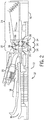
- FIG. 2 is a cross-sectional side view of an embodiment of the gas turbine engine 12 of FIG. 1 taken along a longitudinal axis 32.
- the gas turbine 22 includes three separate stages 34.
- Each stage 34 includes a set of blades or buckets 36 coupled to a rotor wheel 38 that may be rotatably attached to the shaft 26 ( FIG. 1 ).
- the blades 36 extend radially outward from the rotor wheels 38 and are partially disposed within the path of the hot combustion gases.
- a set of flow path seals e.g., turbine flow path seals; see FIG. 5
- the axial retention system axially secures the blades 36 and/or flow path seals to the rotor wheels 38.
- the gas turbine 22 is illustrated as a three-stage turbine, the axial retention system described herein may be employed in any suitable type of turbine with any number of stages and shafts.
- the axial retention system may be included in a single stage gas turbine, in a dual turbine system that includes a low-pressure turbine and a high-pressure turbine, or in a steam turbine.
- the axial retention system described herein may also be employed in a rotary compressor, such as the compressor 18 illustrated in FIGS. 1 and 2 .
- the compressed air from the compressor 18 is then directed into the combustor section 20 where the compressed air is mixed with fuel.
- the mixture of compressed air and fuel is generally burned within the combustor section 20 to generate high-temperature, high-pressure combustion gases, which are used to generate torque within the turbine 22.
- the combustion gases apply motive forces to the blades 36 to turn the wheels 38 (i.e., rotor) about a rotational axis 32.
- the axial retention system may axially lock the rotating segments into the rotor 38 to block disengagement of the rotating segments from the rotor 38 due to centrifugal force loads.
- the axial retention system may provide a simple system for assembling and/or disassembling the rotating segments from the rotor 38.
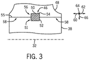
- FIG. 3 is a partial cross-sectional view of an embodiment of the gas turbine engine 12 of FIG. 2 , taken within line 3-3, illustrating the axial retention system 46 for rotating segments 48.
- the rotating segment 48 is coupled to the rotor 38 (e.g., wheel).
- the rotating segment 48 includes a mating axial mount 80 coupled to an axial mount 78 of the rotor 38 in an installed position (see FIGS. 4 and 5 ).
- the rotor 38 includes the rotational axis 32.
- the rotating segment 48 may include the bucket or blade 36 (see FIG. 4 ) or a turbine flow path seal (see FIG. 5 ).
- the axial retention system 46 includes a pin 50 (e.g., shear pin) inserted into an inserted position 51 in both a slot 52 (e.g., pin slot) in the rotor 38 and a mating slot 54 (e.g., pin mating slot) in the rotating segment 48.
- the slot 52 and the mating slot 54 are each configured to support the pin 50 in the inserted position 51 to block axial movement of the mating axial mount 80 relative to the axial mount 78.
- the shape (e.g., cross-section) of the pin 50 may vary.
- the pin 50 may include a square (as illustrated in FIG. 3 ), rectangular, oval, circular, triangular, T, U, or any other shape.
- the shape (e.g., cross-section) of the slot 52 and mating slot 54 may also vary to accommodate the shape of the pin 50.
- the number of pins 50 and respective slots 52 and mating slots 54 may vary along a single interface 55 between the rotating segment 48 and the rotor 38.
- the number of pins 50 and respective slots 52 and mating slots 54 may each range from 1 to 10, 1 to 5, 1 to 3, or 1 to 2 along the interface 55.
- the number for each of the pins 50 and respective slots 52 and mating slots 54 may be 1, 2, 3, 4, 5, 6, 7, 8, 9, 10, or any other number along the interface 55.
- the placement of the slot 52 and mating slot 54 may vary along the interface 55.
- the slot 52 and respective mating slot 54 may be disposed along a central portion 56 of the interface 55, as illustrated, or offset from the central portion 56 towards an outer portion 58 of the interface in axial direction 60 and 62.
- the slot 52 and mating slot 54 extend in a circumferential direction 64 relative to the rotational axis 32. In certain embodiments, the slot 52 and mating slot 54 may extend at an angle relative to the circumferential direction 64. As described in greater detail below, the slot 52 includes a radially accessible portion disposed in the rotor 38 adjacent the rotating segment 48 while the mating axial mount 80 is coupled to the axial mount 78 in the installed position.
- the pin 50 is configured to be inserted into the first slot 52 and the first mating slot 54 in a radial direction 66 followed by the circumferential direction 64 relative to the rotational axis 32.
- the pin 50 in the inserted position 51 is configured to block axial movement in directions 60 and 62 of the mating axial mount of the rotating segment 48 relative to the axial mount of the rotor 38.
- the installation of another rotating segment 48 into the rotor 38 adjacent the pin 50 blocks removal of the pin 50.
- the axial retention system 46 may axially lock the rotating segments 48 into the rotor 38 to block disengagement of the rotating segments 48 from the rotor 38 due to centrifugal force loads.
- the axial retention system 46 may provide a simple system for assembling and/or disassembling the rotating segments 48 from the rotor 38.
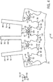
- FIG. 4 is a partial cross-sectional view of an embodiment of the gas turbine engine 12 of FIG. 2 , taken along line 4-4, illustrating the axial retention system 46 for multiple rotating segments (e.g. blades/buckets 36).
- the axial retention system 46 may be utilized for blades 36 attached to rotors 38 in the compressor 18 and/or turbine 22.
- Each rotor 38 e.g., circular rotor
- Each rotor 38 includes blades 36 extending radially 76 outward from the rotor 38.
- the rotor 38 includes a plurality of axial mounts 78 (e.g., recessed axial slot or dovetail slot) for retaining a plurality of mating axial mounts 80 (e.g., protruding axial joint or mating dovetail joint) of the blades 36.
- axial mounts 78 e.g., recessed axial slot or dovetail slot
- mating axial mounts 80 e.g., protruding axial joint or mating dovetail joint
- approximately 50 to 150 blades 36 may be mounted and spaced or offset circumferentially 64 around the rotor 38 and the corresponding axis of rotation 32.
- the blades 82, 84, and 86 have respective axial mating axial mounts 88, 90, and 92 coupled to respective axial mounts 94, 96, and 98 of the rotor 38 in installed positions 100, 102, and 104.
- the axial retention system 46 includes a plurality of slots 52 (e.g., pin slots) spaced circumferentially 64 about the rotational axis 32 of the rotor 38 (e.g., turbomachine rotor).
- the pins 50 are each inserted into inserted positions 51 in both the slots 52 in the rotor 38 and the mating slots 54 (e.g., pin mating slots) in the blades 82, 84, and 86.
- each of the slots 52 and their respective mating slots 54 extend in the circumferential direction 64 relative to the rotational axis 32.
- Each pin 51 in the inserted position 51 is configured to block axial movement of the mating axial mounts 88, 90, and 92 in directions 60 and 62 relative to the axial mounts 94, 96, and 98.
- the blades 84 and 86 in their respective installed positions 102 and 104 block the removal of the pins 51 from slots 52 and mating slots 54 associated with the blades 82 and 84, respectively.
- the slots 52 and mating slots 54 extend in the circumferential direction 64 relative to the rotational axis 32. In certain embodiments, the slots 52 and mating slots 54 may extend at an angle (e.g., approximately 0 to 60 degrees) relative to the circumferential direction 64. Each slot 52 extends only a portion 106 of a circumferential offset 108 between adjacent axial mounts 78. In certain embodiments, each slot 52 extends the entire portion 106 of the circumferential offset 108 between adjacent mounts (see FIG. 17 ).
- each slot 52 includes a radially accessible portion 110 disposed in the rotor 38 adjacent each blade 82, 84, and 86 while the respective mating axial mounts 88, 90, and 92 are coupled to the respective axial mounts 94, 96, and 98 in the installed positions 100, 102, and 104.
- the radially accessible portion 110 e.g., the portion associated with blade 82
- Each pin 50 is configured to insert into each slot 52 and mating slot 54 in the radial direction 66 followed by the circumferential direction 64 relative to the rotational axis 32.
- the blades 84 and 86 cover the radially accessible portion 110 of the slots 52 while the respective mating axial mounts 90 and 92 are coupled to respective axial mounts 96 and 98 in the installed positions 102 and 104.
- the axial retention system 46 may axially lock the blades 36 into the rotor 38 to block disengagement of the blades 36 from the rotor 38 due to centrifugal force loads.
- the axial retention system 46 may provide a simple system for assembling and/or disassembling the blades 36 from the rotor 38.
- FIG. 5 is a partial cross-sectional view of an embodiment of the rotor 38 coupled to multiple turbine flow path seals 120 having the axial retention system 46 for the turbine flow path seals 120.
- the axial retention system 46 is as described in FIG. 4 except the rotor 38 is coupled to turbine flow path seals 120.
- approximately 50 to 150 turbine flow path seals 120 may be mounted and spaced or offset circumferentially 64 around the rotor 38 and the corresponding axis of rotation 32.
- the axial retention system 46 may axially lock the turbine flow path seals 120 into the rotor 38 to block disengagement of the seals 120 from the rotor 38 due to centrifugal force loads.
- the axial retention system 46 may provide a simple system for assembling and/or disassembling the seals 120 from the rotor 38.
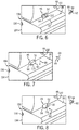
- FIGS. 6-9 are partial perspective views of an embodiment of a rotor and one or more rotating segments 48 illustrating the assembly of the axial retention system 46.
- the rotor 38 and the rotating segments 48 are as described above.
- a first mating axial mount 130 e.g., protruding axial joint or mating dovetail joint
- a first rotating segment 132 e.g., blade, bucket, or turbine flow path seal
- a first axial mount 134 e.g., recessed axial slot or dovetail slot
- the rotor 38 includes the slot 52 (e.g., pin slot) and the first rotating segment 132 includes the mating slot 54.
- the rotating segments 48 may be inserted generally in an axial direction 62 but at an angle or skewed relative to the rotational axis 32 of the rotor 38.
- the slot 52 includes the radially accessible portion 110 disposed in the rotor 38 adjacent the first rotating segment 132 while the first mating axial mount 130 is coupled to the first axial mount 134 in the first installed position 136.
- the slot 52 and mating slot 54 extend in the circumferential direction 64 relative to the rotational axis 32.
- the slot 52 and mating slot 54 are each configured to support the pin 50 in the inserted position 51 to block axial movement of the first mating axial mount 130 in the axial directions 60 and 62 relative to the first axial mount 134.
- the pin 50 is then inserted in the radial direction 66 relative to the rotational axis 32 into the radially accessible portion 110 of the slot 52. Subsequent to insertion in the radial direction 66, the pin 50 is inserted in the circumferential direction 64 relative to the rotational axis 32 into the slot 52 and the mating slot 54 as illustrated in FIG. 8 . The pin 50 is inserted in its entirety into the slot 52 and mating slot 54 so that no portion of the pin 50 extends into the radially accessible portion 110. The pin 50 in the installed position 51 blocks axial movement of the first mating axial mount 130 in the axial directions 60 and 62 relative to the first axial mount 134.
- a second mating axial mount 146 e.g., protruding axial joint or mating dovetail joint
- a second rotating segment 148 e.g., blade, bucket, or turbine flow path seal
- a second axial mount 150 e.g., recessed axial slot or dovetail slot
- the second rotating segment 148 in the second installed position 152 blocks removal of the pin 50.
- the second rotating segment 148 covers radially accessible portion 110 while disposed in the second installed position 152.
- the rotor 38 includes the slot 52 (e.g., pin slot) and the first rotating segment 132 includes the mating slot 54.
- the slot 52 includes the radially accessible portion 110 disposed in the rotor 38 adjacent the first rotating segment 132 while the first mating axial mount 130 is coupled to the first axial mount 134 in the first installed position 136.
- the slot 52 and mating slot 54 extend in the circumferential direction 64 relative to the rotational axis 32.
- the slot and mating slot 54 are each configured to support the pin 50 in the inserted position 51 to block axial movement of the first mating axial mount 130 in the axial directions 60 and 62 relative to the first axial mount 134.
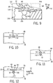
- FIGS. 10-17 illustrate various embodiments of arrangements and shapes of the pins 50, slots 52 of the rotor 38, and mating slots 54 of the rotating segment 48 (e.g., blade, turbine, or turbine flow path seal) of the axial retention system 46.
- FIGS. 10-16 are partial cross-sectional views of an embodiment of the turbine engine 12 of FIG. 2 , taken within line 3-3, of the pins 50, slots 52, and mating slots 54 of the axial retention system 46.
- the axial retention system 46 is configured to block axial movement in directions 60 and 62 of the mating axial mount of the rotating segment 48 relative to the axial mount of the rotor 38.
- the axial retention system 46 may axially lock the rotating segments 48 into the rotor 38 to block disengagement of the rotating segments 48 from the rotor 38 due to centrifugal force loads.
- the axial retention system 46 may provide a simple system for assembling and/or disassembling the rotating segments 48 from the rotor 38.
- the embodiments below are not intended to be limiting, but rather the embodiments are intended to provide some examples of the various arrangements and shapes of the pins 50, slots 52, and mating slots 54.
- the axial retention system 46 illustrated in FIGS. 9-13 may include a single pin 50 and corresponding slot 52 and mating slot 54.
- the pin 50 includes an elliptical cross-section.
- the pin 50 includes a circular cross-section in FIG. 9 and an oval cross section in FIG. 10 .
- the corresponding slot 52 and mating slot 54 form an elliptically-shaped recess 162.
- the pin 50 may include a T-shape as illustrated in FIG. 12 .
- the pin 50 includes a first portion 164 and a second portion 166.
- the first portion 164 runs along the interface 55 between the rotor 38 and rotating segment 48 in the axial directions 60 and 62.
- the second portion 166 extends in radial direction 66.
- the first portion 164 of the pin 50 associates with the mating slot 54 (e.g., rectilinear recess 168) and the second portion 166 associates with the slot 52 (e.g., rectilinear recess 170).
- the orientation of the pin 50 may be inverted to form an upside down T-shape, where the first portion 164 associates with the slot 52 and the second portion 166 associates with the mating slot 166.
- the pin 50 includes a U-shape.
- the pin 50 includes a base portion 172 and extension portions 174 and 176.
- the base portion 172 runs along the interface 55 between the rotor 38 and rotating segment 48 in the axial directions 60 and 62.
- the extension portions 174 and 176 extend in the radial direction 76.
- the base portion of the pin 50 associates with the slot 52 (e.g., rectilinear recess 178) and the extension portions 174 and 176 associate with the mating slot 54 (e.g., rectilinear recesses 180 and 182).
- the orientation of the pin 50 may be inverted to form an upside down U-shape, where the base portion 172 associates with the mating slot 54 and the extension portions 174 and 176 associate with the slot 52.
- the pin 50 includes a pentagonal cross-section.
- the pin 50 includes a base portion 184 and a triangular portion 186.
- the base portion 184 runs along the interface 55 between the rotor 38 and rotating segment 48 in the axial directions 60 and 62.
- the triangular portion 186 tapers or narrows in the radial direction 76.
- the base portion 184 associates with the slot 52 (e.g., rectilinear recess 188) and the triangular portion 186 associates with the mating slot 54 (e.g., triangular recess 190).
- the orientation of the pin 50 may be inverted, where the triangular portion 186 associates with the slot 52 and tapers or narrows in the radial direction 66, and the base portion 184 associates with the mating slot 54.
- the axial retention system 46 includes multiple pins 50 (e.g., pins 191 and 192) and corresponding slots 52 (e.g., slots 194 and 196) and mating slots 54 (e.g., mating slots 198 and 200) along the single interface 55 between the rotating segment 48 and the rotor 38.
- Each pin 190 and 192 includes a rectilinear cross-section (e.g., square).
- the slots 194 and 196 and respective mating slots 198 and 200 form rectilinear recesses 202 and 204.
- the number of pins 50 and respective slots 52 and mating slots 54 may range from 1 to 10, 1 to 5, 1 to 3, or 1 to 2 each along the interface 55.
- the number of pins 50 and respective slots 52 and mating slots 54 may be 1, 2, 3, 4, 5, 6, 7, 8, 9, 10, or any other number each along the interface 55.
- the placement of the slot 52 and mating slot 54 may vary along the interface 55. As illustrated, the slot 52 and respective mating slot 54 are disposed offset from the central portion 56 towards an outer portion 58 of the interface 55 in axial direction 60 and 62. In certain embodiments, the slot 52 and respective mating slot 54 may be disposed along a central portion 56 of the interface 55 (see FIGS. 10-14 ).
- FIG. 16 is a partial cross-sectional top view of an embodiment of the rotor 38 illustrating the axial retention system 46 (e.g., angled slot) for the rotating segments 48.
- the rotor 38 includes the slot 52 as described above.
- the slot 52 includes a portion 214 and the radially accessible portion 110.
- the portion 214 and radially accessible portion 110 are disposed on opposite sides of an interface 215 between adjacent rotating segments 48.
- the portion 214 is covered when a first rotating segment 48 is inserted into the installed position.
- the pin 50 may be inserted first in the radial direction 66 into the radially accessible portion 110 of the slot 52 and then inserted in the circumferential direction 64 into portion 214 of the slot 52 into the inserted position 51. As illustrated in FIG.
- the slot 52 (as well as the mating slot 54) extends in the circumferential direction 64 relative to the rotational axis 32.
- the slot 52 and mating slot 54 may extend at an angle 216 relative to the circumferential direction 64.
- the angle 216 may range from approximately 0 to 60 degrees, 0 to 45 degrees, 0 to 30 degrees, 0 to 15 degrees, 15 to 30 degrees, 30 to 45 degrees, and any subrange therein.
- the angle 216 may be approximately 0, 5, 10, 15, 20, 25, 30, 35, 40, 45, 50, 55, or 60 degrees, or any other angle.
- FIG. 17 is a partial perspective view of an embodiment of the rotor 38 and the rotating segment 48 illustrating the axial retention system 46 comprising an L-shaped pin of the turbomachine retention system of the present invention with the pin 50 in the inserted position to prevent axial movement of rotating segment 48 relative to the rotor 38.
- the axial retention system 46 of FIG. 17 functions as described in the above embodiments.
- the pin 50 includes an L-shape that includes an upper portion 226 and a lower portion 228.
- the upper portion 226 includes an angled side 230 that tapers or narrows generally in radial direction 76 towards an end 232 (e.g., tapered end) of the upper portion 226 of the pin 50.
- the upper portion 226 of the pin 50 associates with the mating slot 54.
- the mating slot 54 includes a recess 234 that includes a tapered portion 236 that prevents the pin 50 from being inserted backwards into the mating slot 54 (i.e., prevents the insertion of the lower portion 228 into the mating slot 54).
- the lower portion 228 of the pin 50 associates with the slot 52.
- the lower portion 228 of the pin 50 extends into the radially accessible portion 110 of the slot 52 while in the inserted position.
- the slot 52 extends the entire portion 106 of the circumferential offset 108 between adjacent axial mounts 78 (see FIG. 4 ).
- the lower portion 228 of the pin 50 includes a hole 238 that enables a tool to remove the pin 50 from the inserted position, e.g., during the disassembling of the rotating segments 48 from the rotor 38.
- the axial retention system 46 to maintain the rotating segments 48 (e.g., blades, buckets, or flow path seal) coupled to the rotor 38 in components (e.g., compressor 18 and/or turbine 22) of the turbomachine 10 (e.g., gas turbine engines 12).
- the axial retention system 46 includes the pin 51 configured to be inserted into a first inserted position in both the slot 52 (e.g., recessed axial slot) in the rotor 38 and the mating slot 54 (e.g., formed by a protruding axial joint) in the rotating segment 48.
- the slot 52 and the mating slot 54 extend in the circumferential direction 64 relative to the rotational axis 32 of the rotor 38, and the pin 50 in the inserted position 51 is configured to block axial movement of rotating segment 48 relative to the rotor 38. Insertion of another rotating segment 48 adjacent to the pin 50 blocks removal of the pin 50.
- the axial retention system 46 may axially lock the rotating segments 48 into the rotor 38 to block disengagement of the rotating segments 48 from the rotor 38 due to centrifugal force loads.
- the axial retention system 46 may provide a simple system for assembling and/or disassembling the rotating segments 48 from the rotor 38.
Claims (11)
- Système de rétention axiale d'une turbomachine, comprenant :
une turbomachine, comprenant :un rotor (38) comprenant un axe de rotation (32) ;un premier segment rotatif (132) ayant un premier montant axial d'accouplement (130) couplé à un premier montant axial (134) du rotor dans une première position installée (136) ;une première goupille (50) configurée pour être insérée dans une première position insérée (51) à la fois dans une première fente (52) dans le rotor et dans une première fente d'accouplement (54) dans le premier segment rotatif, dans lequel la première fente (52) et la première fente d'accouplement (54) s'étendent dans une première direction circonférentielle (64) par rapport à l'axe de rotation, et la première goupille (50) dans la première position insérée est configurée pour bloquer le mouvement axial du premier montant axial d'accouplement (130) par rapport au premier montant axial, un deuxième segment rotatif (148) ayant un deuxième montant axial d'accouplement (146) couplé à un deuxième montant axial (150) du rotor dans une deuxième position installée (102), dans lequel le deuxième segment rotatif dans la deuxième position installée est configuré pour bloquer le retrait de la première goupille (50), caractérisé en ce quela première goupille (50) comprend une forme en L ayant une partie supérieure (226) et une partie inférieure (228), la partie inférieure (228) comprend un trou (238) configuré pour permettre le retrait de la première goupille (50) de la première fente (52), la partie supérieure (226) comprend une extrémité conique (232), et la première fente d'accouplement (54) comprend un évidement (234) ayant une partie conique (236) configurée pour permettre l'insertion de l'extrémité conique (232) de la partie supérieure (236) de la première goupille (50) dans la première fente d'accouplement (54) et pour empêcher l'insertion de la partie inférieure (228) de la première goupille (50) dans la première fente d'accouplement (54). - Système selon la revendication 1, dans lequel la turbomachine comprend un moteur de turbine à gaz.
- Système selon la revendication 1 ou 2, dans lequel les premier et deuxième montants axiaux (134, 150) comprennent chacun une fente axiale renfoncée, et les premier et deuxième montants axiaux d'accouplement (130, 146) comprennent chacun un joint axial saillant.
- Système selon l'une quelconque des revendications 1 à 3, dans lequel la première goupille (50) est configurée pour être insérée dans la première fente (52) et la première fente d'accouplement (54) dans une première direction radiale (66) suivie de la première direction circonférentielle (64) par rapport à l'axe de rotation (32).
- Système selon la revendication 1, dans lequel le deuxième segment rotatif (148) recouvre la première partie accessible radialement (110) de la première fente (52), tandis que le deuxième montant axial d'accouplement (146) est couplé au deuxième montant axial (150) dans la deuxième position installée (152).
- Système selon une quelconque revendication précédente, dans lequel la première fente (52) dans le rotor (38) s'étend uniquement sur une partie d'un décalage circonférentiel (108) entre les premier (134) et deuxième (150) montants axiaux.
- Système selon une quelconque revendication précédente, dans lequel les premier (132) et deuxième (148) segments rotatifs comprennent une lame (82, 84, 86) ou un joint d'écoulement (120).
- Système selon une quelconque revendication précédente, dans lequel la turbomachine comprend :une deuxième goupille (192) configurée pour être insérée dans une deuxième position insérée (51) à la fois dans une deuxième fente (194) dans le rotor (38) et dans une deuxième fente d'accouplement (196) dans le deuxième segment rotatif (148), dans lequel la deuxième fente (194) et la deuxième fente d'accouplement (196) s'étendent dans une deuxième direction circonférentielle par rapport à l'axe de rotation (32), et la deuxième goupille (192) dans la deuxième position insérée est configurée pour bloquer le mouvement axial du deuxième montant axial d'accouplement (146) par rapport au deuxième montant axial (150) ; etun troisième segment rotatif (48) ayant un troisième montant axial d'accouplement couplé à un troisième montant axial du rotor (38) dans une troisième position installée (110), dans lequel le troisième segment rotatif (48) dans la troisième position installée (110) est configuré pour bloquer le retrait de la deuxième goupille (192).
- Système selon une quelconque revendication précédente, dans lequel les premier et deuxième montants axiaux (134, 150) comprennent chacun un joint en queue d'aronde, et les premier et deuxième montants axiaux d'accouplement (130, 146) comprennent chacun un joint d'accouplement en queue d'aronde.
- Procédé d'assemblage d'un système de rétention axiale d'une turbomachine, comprenant :l'insertion axiale d'un premier montant axial d'accouplement (130) d'un premier segment rotatif (132) dans un premier montant axial d'un rotor ;l'insertion d'une première goupille (50) dans une direction radiale par rapport à l'axe de rotation (32) du rotor (38) dans une partie accessible radialement (110) d'une première fente (52) du rotor ;l'insertion de la première goupille dans une première direction circonférentielle par rapport à l'axe de rotation du rotor dans la première fente du rotor et une première fente d'accouplement (54) du premier segment rotatif dans une première position insérée (51), dans lequel la première goupille est configurée pour bloquer le mouvement axial du premier montant axial d'accouplement (130) par rapport au premier montant axial (134) ; etl'insertion axiale d'un deuxième montant axial d'accouplement (146) d'un deuxième segment rotatif (148) dans un deuxième montant axial (150) du rotor pour bloquer le retrait de la première goupille (50) ;caractérisé en ce que,la première goupille (50) comprend une forme en L avec une partie supérieure (226) et une partie inférieure (228), la partie inférieure (228) comprend un trou (238) configuré pour permettre le retrait de la première goupille (50) de la première fente (52), la partie supérieure (226) comprend une extrémité conique (232), et la première fente d'accouplement (54) comprend un renfoncement (234) ayant une partie conique (236) configurée pour permettre l'insertion de l'extrémité conique (232) de la partie supérieure (236) de la première goupille (50) dans la première fente d'accouplement (54) et pour empêcher l'insertion de la partie inférieure (228) de la première goupille (50) dans la première fente d'accouplement (54).
- Procédé selon la revendication 10, comprenant :l'insertion d'une deuxième goupille (192) dans une deuxième direction circonférentielle par rapport à l'axe de rotation (32) du rotor dans une deuxième fente (194) du rotor (38) et une deuxième fente d'accouplement (196) du deuxième segment rotatif (148) dans une deuxième position insérée (110) ; etl'insertion axiale d'un troisième montant axial d'accouplement d'un troisième segment rotatif dans un troisième montant axial du rotor (38) pour bloquer le retrait de la deuxième goupille (192).
Applications Claiming Priority (1)
| Application Number | Priority Date | Filing Date | Title |
|---|---|---|---|
| US13/344,421 US9051845B2 (en) | 2012-01-05 | 2012-01-05 | System for axial retention of rotating segments of a turbine |
Publications (3)
| Publication Number | Publication Date |
|---|---|
| EP2613000A2 EP2613000A2 (fr) | 2013-07-10 |
| EP2613000A3 EP2613000A3 (fr) | 2017-07-12 |
| EP2613000B1 true EP2613000B1 (fr) | 2021-03-17 |
Family
ID=47678513
Family Applications (1)
| Application Number | Title | Priority Date | Filing Date |
|---|---|---|---|
| EP12199013.9A Active EP2613000B1 (fr) | 2012-01-05 | 2012-12-21 | Système de rétention axiale de segments rotatifs d'une turbine et procedé associé |
Country Status (5)
| Country | Link |
|---|---|
| US (1) | US9051845B2 (fr) |
| EP (1) | EP2613000B1 (fr) |
| JP (1) | JP6063738B2 (fr) |
| CN (1) | CN103195515B (fr) |
| RU (1) | RU2607982C2 (fr) |
Families Citing this family (14)
| Publication number | Priority date | Publication date | Assignee | Title |
|---|---|---|---|---|
| US9726026B2 (en) * | 2012-06-06 | 2017-08-08 | General Electric Company | Turbine rotor and blade assembly with multi-piece locking blade |
| US9382801B2 (en) | 2014-02-26 | 2016-07-05 | General Electric Company | Method for removing a rotor bucket from a turbomachine rotor wheel |
| US9777586B2 (en) | 2014-12-31 | 2017-10-03 | General Electric Company | Flowpath boundary and rotor assemblies in gas turbines |
| US20160305260A1 (en) * | 2015-03-04 | 2016-10-20 | Rolls-Royce North American Technologies, Inc. | Bladed wheel with separable platform |
| KR101689085B1 (ko) | 2015-08-03 | 2017-01-02 | 두산중공업 주식회사 | 터빈용 마지막 버켓 고정장치 및 이를 이용한 마지막 버켓의 조립 방법 |
| US10227880B2 (en) * | 2015-11-10 | 2019-03-12 | General Electric Company | Turbine blade attachment mechanism |
| US9682756B1 (en) | 2016-10-17 | 2017-06-20 | General Electric Company | System for composite marine propellers |
| US10633067B2 (en) | 2016-10-17 | 2020-04-28 | General Electric Company | Method and system for improving flow characteristics in marine propellers |
| US10703452B2 (en) | 2016-10-17 | 2020-07-07 | General Electric Company | Apparatus and system for propeller blade aft retention |
| US10689073B2 (en) | 2016-10-17 | 2020-06-23 | General Electric Company | Apparatus and system for marine propeller blade dovetail stress reduction |
| US10486785B2 (en) | 2016-10-17 | 2019-11-26 | General Electric Company | Propeller assembly and method of assembling |
| US11052982B2 (en) | 2016-10-17 | 2021-07-06 | General Electric Company | Apparatus for dovetail chord relief for marine propeller |
| JP2023090250A (ja) * | 2021-12-17 | 2023-06-29 | 三菱重工コンプレッサ株式会社 | 蒸気タービンのロータ、蒸気タービン、及び動翼の固定方法 |
| US20240060432A1 (en) * | 2022-08-19 | 2024-02-22 | Pratt & Whitney Canada Corp. | Simultaneously disassembling rotor blades from a gas turbine engine rotor disk |
Family Cites Families (39)
| Publication number | Priority date | Publication date | Assignee | Title |
|---|---|---|---|---|
| BE537113A (fr) * | 1954-04-05 | |||
| US3202398A (en) * | 1962-11-05 | 1965-08-24 | James E Webb | Locking device for turbine rotor blades |
| US3198485A (en) * | 1963-09-26 | 1965-08-03 | Gen Motors Corp | Turbine blade lock |
| US3575522A (en) * | 1968-08-30 | 1971-04-20 | Gen Motors Corp | Turbine cooling |
| US3930751A (en) * | 1974-07-05 | 1976-01-06 | Carrier Corporation | Bucket locking mechanism |
| US3904317A (en) * | 1974-11-27 | 1975-09-09 | Gen Electric | Bucket locking mechanism |
| US4094615A (en) | 1976-12-27 | 1978-06-13 | Electric Power Research Institute, Inc. | Blade attachment structure for gas turbine rotor |
| JPS5468005U (fr) * | 1977-10-24 | 1979-05-15 | ||
| US4566857A (en) | 1980-12-19 | 1986-01-28 | United Technologies Corporation | Locking of rotor blades on a rotor disk |
| FR2507679A1 (fr) | 1981-06-12 | 1982-12-17 | Snecma | Dispositif de verrouillage d'une aube de rotor de turbomachine |
| JPS59172202U (ja) * | 1983-05-06 | 1984-11-17 | 株式会社日立製作所 | 動翼の固定取りはずし構造 |
| JPS60192201U (ja) * | 1984-05-30 | 1985-12-20 | 株式会社東芝 | 蒸気タ−ビンの動翼固定構造 |
| JPS60195904U (ja) * | 1984-06-08 | 1985-12-27 | 株式会社日立製作所 | タ−ビン動翼 |
| JPS62139904A (ja) * | 1985-12-12 | 1987-06-23 | Toshiba Corp | タ−ビン動翼の固定装置 |
| US4676723A (en) | 1986-03-26 | 1987-06-30 | Westinghouse Electric Corp. | Locking system for a turbine side entry blade |
| US4767275A (en) * | 1986-07-11 | 1988-08-30 | Westinghouse Electric Corp. | Locking pin system for turbine curved root side entry closing blades |
| JPS63189602A (ja) * | 1987-01-30 | 1988-08-05 | Toshiba Corp | タ−ビン冷却装置 |
| US4883405A (en) * | 1987-11-13 | 1989-11-28 | The United States Of America As Represented By The Secretary Of The Air Force | Turbine nozzle mounting arrangement |
| US4915587A (en) * | 1988-10-24 | 1990-04-10 | Westinghouse Electric Corp. | Apparatus for locking side entry blades into a rotor |
| US5151013A (en) | 1990-12-27 | 1992-09-29 | United Technologies Corporation | Blade lock for a rotor disk and rotor blade assembly |
| US5286168A (en) * | 1992-01-31 | 1994-02-15 | Westinghouse Electric Corp. | Freestanding mixed tuned blade |
| US5242270A (en) * | 1992-01-31 | 1993-09-07 | Westinghouse Electric Corp. | Platform motion restraints for freestanding turbine blades |
| US6109877A (en) | 1998-11-23 | 2000-08-29 | Pratt & Whitney Canada Corp. | Turbine blade-to-disk retention device |
| DE10140259C1 (de) * | 2001-08-16 | 2003-01-30 | Man B & W Diesel Ag | Axialturbine |
| US6533550B1 (en) | 2001-10-23 | 2003-03-18 | Pratt & Whitney Canada Corp. | Blade retention |
| ITMI20012783A1 (it) * | 2001-12-21 | 2003-06-21 | Nuovo Pignone Spa | Sistema di connessione e bloccaggio di pale rotoriche di un compressore assiale |
| US6837686B2 (en) | 2002-09-27 | 2005-01-04 | Pratt & Whitney Canada Corp. | Blade retention scheme using a retention tab |
| US6722848B1 (en) * | 2002-10-31 | 2004-04-20 | General Electric Company | Turbine nozzle retention apparatus at the carrier horizontal joint face |
| DE10348198A1 (de) | 2003-10-16 | 2005-05-12 | Rolls Royce Deutschland | Schaufelrückhaltevorrichtung |
| DE102004017193A1 (de) | 2004-04-07 | 2005-10-27 | Rolls-Royce Deutschland Ltd & Co Kg | Turbinenschaufelarretiervorrichtung |
| US7435055B2 (en) * | 2005-03-29 | 2008-10-14 | Siemens Power Generation, Inc. | Locking spacer assembly for a turbine engine |
| DE102005024932A1 (de) | 2005-05-31 | 2006-12-07 | Rolls-Royce Deutschland Ltd & Co Kg | Turbinenschaufelaxialsperre |
| WO2007028703A1 (fr) * | 2005-09-07 | 2007-03-15 | Siemens Aktiengesellschaft | Systeme de retenue axiale de d'aubes mobiles dans un rotor et utilisation dudit systeme |
| US8070431B2 (en) * | 2007-10-31 | 2011-12-06 | General Electric Company | Fully contained retention pin for a turbine nozzle |
| US8061995B2 (en) * | 2008-01-10 | 2011-11-22 | General Electric Company | Machine component retention |
| JP4886735B2 (ja) * | 2008-05-26 | 2012-02-29 | 株式会社東芝 | タービン動翼組立体および蒸気タービン |
| US8221062B2 (en) | 2009-01-14 | 2012-07-17 | General Electric Company | Device and system for reducing secondary air flow in a gas turbine |
| US8485784B2 (en) * | 2009-07-14 | 2013-07-16 | General Electric Company | Turbine bucket lockwire rotation prevention |
| US8459953B2 (en) * | 2010-01-19 | 2013-06-11 | General Electric Company | Seal plate and bucket retention pin assembly |
-
2012
- 2012-01-05 US US13/344,421 patent/US9051845B2/en active Active
- 2012-12-21 EP EP12199013.9A patent/EP2613000B1/fr active Active
- 2012-12-27 RU RU2012158317A patent/RU2607982C2/ru active
- 2012-12-27 JP JP2012283883A patent/JP6063738B2/ja active Active
-
2013
- 2013-01-05 CN CN201310003067.6A patent/CN103195515B/zh active Active
Non-Patent Citations (1)
| Title |
|---|
| None * |
Also Published As
| Publication number | Publication date |
|---|---|
| RU2607982C2 (ru) | 2017-01-11 |
| EP2613000A2 (fr) | 2013-07-10 |
| US20130177429A1 (en) | 2013-07-11 |
| US9051845B2 (en) | 2015-06-09 |
| RU2012158317A (ru) | 2014-07-10 |
| EP2613000A3 (fr) | 2017-07-12 |
| JP6063738B2 (ja) | 2017-01-18 |
| CN103195515B (zh) | 2016-08-17 |
| CN103195515A (zh) | 2013-07-10 |
| JP2013139809A (ja) | 2013-07-18 |
Similar Documents
| Publication | Publication Date | Title |
|---|---|---|
| EP2613000B1 (fr) | Système de rétention axiale de segments rotatifs d'une turbine et procedé associé | |
| US9181810B2 (en) | System and method for covering a blade mounting region of turbine blades | |
| US8206119B2 (en) | Turbine coverplate systems | |
| EP2971693B1 (fr) | Dispositif d'étanchéité de disque de rotor de turbine à gaz | |
| US9291061B2 (en) | Turbomachine blade tip shroud with parallel casing configuration | |
| US8511976B2 (en) | Turbine seal system | |
| EP2535523A2 (fr) | Système d'étanchéité de turbine et procédé de son assemblage | |
| EP2586988B1 (fr) | Ensemble de plaque de couverture de turbine | |
| EP2650484A1 (fr) | Configuration de joint inter-étages d'une turbine | |
| WO2013126213A1 (fr) | Ensemble d'aube pour moteur à turbine à gaz | |
| US20100064516A1 (en) | Stator Ring Configuration | |
| EP2546461A1 (fr) | Ensemble de rotor et moteur à turbine à gaz associé | |
| US9896946B2 (en) | Gas turbine engine rotor assembly and method of assembling the same | |
| EP3418496A2 (fr) | Pale de rotor de turbomachine | |
| US9540955B2 (en) | Stator assembly | |
| EP3088662A1 (fr) | Joint interétage de turbine à plusieurs étages et procédé d'assemblage | |
| EP3693541B1 (fr) | Disque de rotor de turbine à gaz doté d'une fonctionnalité de protection de grille |
Legal Events
| Date | Code | Title | Description |
|---|---|---|---|
| PUAI | Public reference made under article 153(3) epc to a published international application that has entered the european phase |
Free format text: ORIGINAL CODE: 0009012 |
|
| AK | Designated contracting states |
Kind code of ref document: A2 Designated state(s): AL AT BE BG CH CY CZ DE DK EE ES FI FR GB GR HR HU IE IS IT LI LT LU LV MC MK MT NL NO PL PT RO RS SE SI SK SM TR |
|
| AX | Request for extension of the european patent |
Extension state: BA ME |
|
| PUAL | Search report despatched |
Free format text: ORIGINAL CODE: 0009013 |
|
| AK | Designated contracting states |
Kind code of ref document: A3 Designated state(s): AL AT BE BG CH CY CZ DE DK EE ES FI FR GB GR HR HU IE IS IT LI LT LU LV MC MK MT NL NO PL PT RO RS SE SI SK SM TR |
|
| AX | Request for extension of the european patent |
Extension state: BA ME |
|
| RIC1 | Information provided on ipc code assigned before grant |
Ipc: F01D 5/30 20060101AFI20170607BHEP Ipc: F01D 5/22 20060101ALI20170607BHEP Ipc: F01D 5/32 20060101ALI20170607BHEP |
|
| STAA | Information on the status of an ep patent application or granted ep patent |
Free format text: STATUS: REQUEST FOR EXAMINATION WAS MADE |
|
| 17P | Request for examination filed |
Effective date: 20180112 |
|
| RBV | Designated contracting states (corrected) |
Designated state(s): AL AT BE BG CH CY CZ DE DK EE ES FI FR GB GR HR HU IE IS IT LI LT LU LV MC MK MT NL NO PL PT RO RS SE SI SK SM TR |
|
| STAA | Information on the status of an ep patent application or granted ep patent |
Free format text: STATUS: EXAMINATION IS IN PROGRESS |
|
| 17Q | First examination report despatched |
Effective date: 20190617 |
|
| GRAP | Despatch of communication of intention to grant a patent |
Free format text: ORIGINAL CODE: EPIDOSNIGR1 |
|
| STAA | Information on the status of an ep patent application or granted ep patent |
Free format text: STATUS: GRANT OF PATENT IS INTENDED |
|
| INTG | Intention to grant announced |
Effective date: 20200408 |
|
| GRAJ | Information related to disapproval of communication of intention to grant by the applicant or resumption of examination proceedings by the epo deleted |
Free format text: ORIGINAL CODE: EPIDOSDIGR1 |
|
| STAA | Information on the status of an ep patent application or granted ep patent |
Free format text: STATUS: EXAMINATION IS IN PROGRESS |
|
| INTC | Intention to grant announced (deleted) | ||
| GRAP | Despatch of communication of intention to grant a patent |
Free format text: ORIGINAL CODE: EPIDOSNIGR1 |
|
| STAA | Information on the status of an ep patent application or granted ep patent |
Free format text: STATUS: GRANT OF PATENT IS INTENDED |
|
| INTG | Intention to grant announced |
Effective date: 20200827 |
|
| GRAS | Grant fee paid |
Free format text: ORIGINAL CODE: EPIDOSNIGR3 |
|
| STAA | Information on the status of an ep patent application or granted ep patent |
Free format text: STATUS: GRANT OF PATENT IS INTENDED |
|
| GRAA | (expected) grant |
Free format text: ORIGINAL CODE: 0009210 |
|
| STAA | Information on the status of an ep patent application or granted ep patent |
Free format text: STATUS: THE PATENT HAS BEEN GRANTED |
|
| AK | Designated contracting states |
Kind code of ref document: B1 Designated state(s): AL AT BE BG CH CY CZ DE DK EE ES FI FR GB GR HR HU IE IS IT LI LT LU LV MC MK MT NL NO PL PT RO RS SE SI SK SM TR |
|
| REG | Reference to a national code |
Ref country code: GB Ref legal event code: FG4D |
|
| REG | Reference to a national code |
Ref country code: CH Ref legal event code: EP |
|
| REG | Reference to a national code |
Ref country code: DE Ref legal event code: R096 Ref document number: 602012074809 Country of ref document: DE |
|
| REG | Reference to a national code |
Ref country code: IE Ref legal event code: FG4D |
|
| REG | Reference to a national code |
Ref country code: AT Ref legal event code: REF Ref document number: 1372409 Country of ref document: AT Kind code of ref document: T Effective date: 20210415 |
|
| REG | Reference to a national code |
Ref country code: LT Ref legal event code: MG9D |
|
| PG25 | Lapsed in a contracting state [announced via postgrant information from national office to epo] |
Ref country code: GR Free format text: LAPSE BECAUSE OF FAILURE TO SUBMIT A TRANSLATION OF THE DESCRIPTION OR TO PAY THE FEE WITHIN THE PRESCRIBED TIME-LIMIT Effective date: 20210618 Ref country code: HR Free format text: LAPSE BECAUSE OF FAILURE TO SUBMIT A TRANSLATION OF THE DESCRIPTION OR TO PAY THE FEE WITHIN THE PRESCRIBED TIME-LIMIT Effective date: 20210317 Ref country code: FI Free format text: LAPSE BECAUSE OF FAILURE TO SUBMIT A TRANSLATION OF THE DESCRIPTION OR TO PAY THE FEE WITHIN THE PRESCRIBED TIME-LIMIT Effective date: 20210317 Ref country code: BG Free format text: LAPSE BECAUSE OF FAILURE TO SUBMIT A TRANSLATION OF THE DESCRIPTION OR TO PAY THE FEE WITHIN THE PRESCRIBED TIME-LIMIT Effective date: 20210617 Ref country code: NO Free format text: LAPSE BECAUSE OF FAILURE TO SUBMIT A TRANSLATION OF THE DESCRIPTION OR TO PAY THE FEE WITHIN THE PRESCRIBED TIME-LIMIT Effective date: 20210617 |
|
| REG | Reference to a national code |
Ref country code: AT Ref legal event code: MK05 Ref document number: 1372409 Country of ref document: AT Kind code of ref document: T Effective date: 20210317 |
|
| PG25 | Lapsed in a contracting state [announced via postgrant information from national office to epo] |
Ref country code: LV Free format text: LAPSE BECAUSE OF FAILURE TO SUBMIT A TRANSLATION OF THE DESCRIPTION OR TO PAY THE FEE WITHIN THE PRESCRIBED TIME-LIMIT Effective date: 20210317 Ref country code: RS Free format text: LAPSE BECAUSE OF FAILURE TO SUBMIT A TRANSLATION OF THE DESCRIPTION OR TO PAY THE FEE WITHIN THE PRESCRIBED TIME-LIMIT Effective date: 20210317 Ref country code: SE Free format text: LAPSE BECAUSE OF FAILURE TO SUBMIT A TRANSLATION OF THE DESCRIPTION OR TO PAY THE FEE WITHIN THE PRESCRIBED TIME-LIMIT Effective date: 20210317 |
|
| PG25 | Lapsed in a contracting state [announced via postgrant information from national office to epo] |
Ref country code: NL Free format text: LAPSE BECAUSE OF FAILURE TO SUBMIT A TRANSLATION OF THE DESCRIPTION OR TO PAY THE FEE WITHIN THE PRESCRIBED TIME-LIMIT Effective date: 20210317 |
|
| PG25 | Lapsed in a contracting state [announced via postgrant information from national office to epo] |
Ref country code: SM Free format text: LAPSE BECAUSE OF FAILURE TO SUBMIT A TRANSLATION OF THE DESCRIPTION OR TO PAY THE FEE WITHIN THE PRESCRIBED TIME-LIMIT Effective date: 20210317 Ref country code: AT Free format text: LAPSE BECAUSE OF FAILURE TO SUBMIT A TRANSLATION OF THE DESCRIPTION OR TO PAY THE FEE WITHIN THE PRESCRIBED TIME-LIMIT Effective date: 20210317 Ref country code: LT Free format text: LAPSE BECAUSE OF FAILURE TO SUBMIT A TRANSLATION OF THE DESCRIPTION OR TO PAY THE FEE WITHIN THE PRESCRIBED TIME-LIMIT Effective date: 20210317 Ref country code: EE Free format text: LAPSE BECAUSE OF FAILURE TO SUBMIT A TRANSLATION OF THE DESCRIPTION OR TO PAY THE FEE WITHIN THE PRESCRIBED TIME-LIMIT Effective date: 20210317 Ref country code: CZ Free format text: LAPSE BECAUSE OF FAILURE TO SUBMIT A TRANSLATION OF THE DESCRIPTION OR TO PAY THE FEE WITHIN THE PRESCRIBED TIME-LIMIT Effective date: 20210317 |
|
| PG25 | Lapsed in a contracting state [announced via postgrant information from national office to epo] |
Ref country code: SK Free format text: LAPSE BECAUSE OF FAILURE TO SUBMIT A TRANSLATION OF THE DESCRIPTION OR TO PAY THE FEE WITHIN THE PRESCRIBED TIME-LIMIT Effective date: 20210317 Ref country code: PL Free format text: LAPSE BECAUSE OF FAILURE TO SUBMIT A TRANSLATION OF THE DESCRIPTION OR TO PAY THE FEE WITHIN THE PRESCRIBED TIME-LIMIT Effective date: 20210317 Ref country code: PT Free format text: LAPSE BECAUSE OF FAILURE TO SUBMIT A TRANSLATION OF THE DESCRIPTION OR TO PAY THE FEE WITHIN THE PRESCRIBED TIME-LIMIT Effective date: 20210719 Ref country code: ES Free format text: LAPSE BECAUSE OF FAILURE TO SUBMIT A TRANSLATION OF THE DESCRIPTION OR TO PAY THE FEE WITHIN THE PRESCRIBED TIME-LIMIT Effective date: 20210317 Ref country code: RO Free format text: LAPSE BECAUSE OF FAILURE TO SUBMIT A TRANSLATION OF THE DESCRIPTION OR TO PAY THE FEE WITHIN THE PRESCRIBED TIME-LIMIT Effective date: 20210317 Ref country code: IS Free format text: LAPSE BECAUSE OF FAILURE TO SUBMIT A TRANSLATION OF THE DESCRIPTION OR TO PAY THE FEE WITHIN THE PRESCRIBED TIME-LIMIT Effective date: 20210717 |
|
| REG | Reference to a national code |
Ref country code: DE Ref legal event code: R097 Ref document number: 602012074809 Country of ref document: DE |
|
| PLBE | No opposition filed within time limit |
Free format text: ORIGINAL CODE: 0009261 |
|
| STAA | Information on the status of an ep patent application or granted ep patent |
Free format text: STATUS: NO OPPOSITION FILED WITHIN TIME LIMIT |
|
| PG25 | Lapsed in a contracting state [announced via postgrant information from national office to epo] |
Ref country code: AL Free format text: LAPSE BECAUSE OF FAILURE TO SUBMIT A TRANSLATION OF THE DESCRIPTION OR TO PAY THE FEE WITHIN THE PRESCRIBED TIME-LIMIT Effective date: 20210317 Ref country code: DK Free format text: LAPSE BECAUSE OF FAILURE TO SUBMIT A TRANSLATION OF THE DESCRIPTION OR TO PAY THE FEE WITHIN THE PRESCRIBED TIME-LIMIT Effective date: 20210317 |
|
| 26N | No opposition filed |
Effective date: 20211220 |
|
| PG25 | Lapsed in a contracting state [announced via postgrant information from national office to epo] |
Ref country code: SI Free format text: LAPSE BECAUSE OF FAILURE TO SUBMIT A TRANSLATION OF THE DESCRIPTION OR TO PAY THE FEE WITHIN THE PRESCRIBED TIME-LIMIT Effective date: 20210317 |
|
| PG25 | Lapsed in a contracting state [announced via postgrant information from national office to epo] |
Ref country code: IS Free format text: LAPSE BECAUSE OF FAILURE TO SUBMIT A TRANSLATION OF THE DESCRIPTION OR TO PAY THE FEE WITHIN THE PRESCRIBED TIME-LIMIT Effective date: 20210717 |
|
| PG25 | Lapsed in a contracting state [announced via postgrant information from national office to epo] |
Ref country code: MC Free format text: LAPSE BECAUSE OF FAILURE TO SUBMIT A TRANSLATION OF THE DESCRIPTION OR TO PAY THE FEE WITHIN THE PRESCRIBED TIME-LIMIT Effective date: 20210317 |
|
| REG | Reference to a national code |
Ref country code: CH Ref legal event code: PL |
|
| REG | Reference to a national code |
Ref country code: BE Ref legal event code: MM Effective date: 20211231 |
|
| PG25 | Lapsed in a contracting state [announced via postgrant information from national office to epo] |
Ref country code: LU Free format text: LAPSE BECAUSE OF NON-PAYMENT OF DUE FEES Effective date: 20211221 Ref country code: IE Free format text: LAPSE BECAUSE OF NON-PAYMENT OF DUE FEES Effective date: 20211221 |
|
| PG25 | Lapsed in a contracting state [announced via postgrant information from national office to epo] |
Ref country code: FR Free format text: LAPSE BECAUSE OF NON-PAYMENT OF DUE FEES Effective date: 20211231 Ref country code: BE Free format text: LAPSE BECAUSE OF NON-PAYMENT OF DUE FEES Effective date: 20211231 |
|
| PG25 | Lapsed in a contracting state [announced via postgrant information from national office to epo] |
Ref country code: LI Free format text: LAPSE BECAUSE OF NON-PAYMENT OF DUE FEES Effective date: 20211231 Ref country code: CH Free format text: LAPSE BECAUSE OF NON-PAYMENT OF DUE FEES Effective date: 20211231 |
|
| PGFP | Annual fee paid to national office [announced via postgrant information from national office to epo] |
Ref country code: IT Payment date: 20221122 Year of fee payment: 11 |
|
| PG25 | Lapsed in a contracting state [announced via postgrant information from national office to epo] |
Ref country code: HU Free format text: LAPSE BECAUSE OF FAILURE TO SUBMIT A TRANSLATION OF THE DESCRIPTION OR TO PAY THE FEE WITHIN THE PRESCRIBED TIME-LIMIT; INVALID AB INITIO Effective date: 20121221 Ref country code: CY Free format text: LAPSE BECAUSE OF FAILURE TO SUBMIT A TRANSLATION OF THE DESCRIPTION OR TO PAY THE FEE WITHIN THE PRESCRIBED TIME-LIMIT Effective date: 20210317 |
|
| REG | Reference to a national code |
Ref country code: DE Ref legal event code: R081 Ref document number: 602012074809 Country of ref document: DE Owner name: GENERAL ELECTRIC TECHNOLOGY GMBH, CH Free format text: FORMER OWNER: GENERAL ELECTRIC COMPANY, SCHENECTADY, NY, US |
|
| PGFP | Annual fee paid to national office [announced via postgrant information from national office to epo] |
Ref country code: GB Payment date: 20231121 Year of fee payment: 12 |
|
| PGFP | Annual fee paid to national office [announced via postgrant information from national office to epo] |
Ref country code: DE Payment date: 20231121 Year of fee payment: 12 |
|
| REG | Reference to a national code |
Ref country code: GB Ref legal event code: 732E Free format text: REGISTERED BETWEEN 20240222 AND 20240228 |