EP2610588A2 - Taux micro de capteur de rotation et procédé pour faire fonctionner un taux micro de capteur de rotation - Google Patents
Taux micro de capteur de rotation et procédé pour faire fonctionner un taux micro de capteur de rotation Download PDFInfo
- Publication number
- EP2610588A2 EP2610588A2 EP20120197114 EP12197114A EP2610588A2 EP 2610588 A2 EP2610588 A2 EP 2610588A2 EP 20120197114 EP20120197114 EP 20120197114 EP 12197114 A EP12197114 A EP 12197114A EP 2610588 A2 EP2610588 A2 EP 2610588A2
- Authority
- EP
- European Patent Office
- Prior art keywords
- masses
- sensor
- driving
- axis
- rotation
- Prior art date
- Legal status (The legal status is an assumption and is not a legal conclusion. Google has not performed a legal analysis and makes no representation as to the accuracy of the status listed.)
- Granted
Links
Images

Classifications
-
- G—PHYSICS
- G01—MEASURING; TESTING
- G01C—MEASURING DISTANCES, LEVELS OR BEARINGS; SURVEYING; NAVIGATION; GYROSCOPIC INSTRUMENTS; PHOTOGRAMMETRY OR VIDEOGRAMMETRY
- G01C19/00—Gyroscopes; Turn-sensitive devices using vibrating masses; Turn-sensitive devices without moving masses; Measuring angular rate using gyroscopic effects
- G01C19/56—Turn-sensitive devices using vibrating masses, e.g. vibratory angular rate sensors based on Coriolis forces
- G01C19/5705—Turn-sensitive devices using vibrating masses, e.g. vibratory angular rate sensors based on Coriolis forces using masses driven in reciprocating rotary motion about an axis
- G01C19/5712—Turn-sensitive devices using vibrating masses, e.g. vibratory angular rate sensors based on Coriolis forces using masses driven in reciprocating rotary motion about an axis the devices involving a micromechanical structure
-
- G—PHYSICS
- G01—MEASURING; TESTING
- G01C—MEASURING DISTANCES, LEVELS OR BEARINGS; SURVEYING; NAVIGATION; GYROSCOPIC INSTRUMENTS; PHOTOGRAMMETRY OR VIDEOGRAMMETRY
- G01C19/00—Gyroscopes; Turn-sensitive devices using vibrating masses; Turn-sensitive devices without moving masses; Measuring angular rate using gyroscopic effects
- G01C19/56—Turn-sensitive devices using vibrating masses, e.g. vibratory angular rate sensors based on Coriolis forces
- G01C19/5719—Turn-sensitive devices using vibrating masses, e.g. vibratory angular rate sensors based on Coriolis forces using planar vibrating masses driven in a translation vibration along an axis
- G01C19/5733—Structural details or topology
- G01C19/574—Structural details or topology the devices having two sensing masses in anti-phase motion
- G01C19/5747—Structural details or topology the devices having two sensing masses in anti-phase motion each sensing mass being connected to a driving mass, e.g. driving frames
-
- G—PHYSICS
- G01—MEASURING; TESTING
- G01C—MEASURING DISTANCES, LEVELS OR BEARINGS; SURVEYING; NAVIGATION; GYROSCOPIC INSTRUMENTS; PHOTOGRAMMETRY OR VIDEOGRAMMETRY
- G01C19/00—Gyroscopes; Turn-sensitive devices using vibrating masses; Turn-sensitive devices without moving masses; Measuring angular rate using gyroscopic effects
- G01C19/56—Turn-sensitive devices using vibrating masses, e.g. vibratory angular rate sensors based on Coriolis forces
-
- G—PHYSICS
- G01—MEASURING; TESTING
- G01C—MEASURING DISTANCES, LEVELS OR BEARINGS; SURVEYING; NAVIGATION; GYROSCOPIC INSTRUMENTS; PHOTOGRAMMETRY OR VIDEOGRAMMETRY
- G01C19/00—Gyroscopes; Turn-sensitive devices using vibrating masses; Turn-sensitive devices without moving masses; Measuring angular rate using gyroscopic effects
- G01C19/02—Rotary gyroscopes
- G01C19/42—Rotary gyroscopes for indicating rate of turn; for integrating rate of turn
-
- G—PHYSICS
- G01—MEASURING; TESTING
- G01C—MEASURING DISTANCES, LEVELS OR BEARINGS; SURVEYING; NAVIGATION; GYROSCOPIC INSTRUMENTS; PHOTOGRAMMETRY OR VIDEOGRAMMETRY
- G01C19/00—Gyroscopes; Turn-sensitive devices using vibrating masses; Turn-sensitive devices without moving masses; Measuring angular rate using gyroscopic effects
- G01C19/56—Turn-sensitive devices using vibrating masses, e.g. vibratory angular rate sensors based on Coriolis forces
- G01C19/5642—Turn-sensitive devices using vibrating masses, e.g. vibratory angular rate sensors based on Coriolis forces using vibrating bars or beams
-
- G—PHYSICS
- G01—MEASURING; TESTING
- G01C—MEASURING DISTANCES, LEVELS OR BEARINGS; SURVEYING; NAVIGATION; GYROSCOPIC INSTRUMENTS; PHOTOGRAMMETRY OR VIDEOGRAMMETRY
- G01C19/00—Gyroscopes; Turn-sensitive devices using vibrating masses; Turn-sensitive devices without moving masses; Measuring angular rate using gyroscopic effects
- G01C19/56—Turn-sensitive devices using vibrating masses, e.g. vibratory angular rate sensors based on Coriolis forces
- G01C19/5719—Turn-sensitive devices using vibrating masses, e.g. vibratory angular rate sensors based on Coriolis forces using planar vibrating masses driven in a translation vibration along an axis
Definitions
- the present invention relates to a micro rate of rotation sensor for detecting a plurality of rates of rotation about orthogonal axes x, y and z, having a substrate, having a plurality of masses disposed in an X-Y plane parallel to the substrate and displaceable relative to the substrate, having a plurality of anchors for attaching the masses to the substrate, having springs for connecting at least some of the masses to at least one adjacent mass or to at least one anchor, having drive elements for oscillating at least some of the masses in the X-direction in order to generate Coriolis forces when the substrate is deflected, and having sensor elements for detecting deflections of the masses due to the Coriolis forces generated, and a method for operating a micro rate of rotation sensor for detecting a plurality of rates of rotation about orthogonal axes x, y and z, having a substrate and driving masses, X-Y sensor masses, and Z sensor masses.
- a generic micro rate of rotation sensor using MEMS technology is known from US 6,308,567 B1 , wherein driving masses are driven to oscillate.
- a rate of rotation about one of the three orthogonal X, Y or Z-axes occurs, masses are deflected out of the drive plane or rotated about the Z-axis.
- Sensor elements are associated with the masses in order to be able to detect the deflections. The deflections occur on the basis of Coriolis forces acting on the masses in case of a corresponding rotary motion and displacing the masses in the corresponding direction.
- the masses are driven toward a center and are rotated about an X-axis, a Y-axis, or a Z-axis due to the Coriolis forces.
- Sensor elements associated with said masses detect the corresponding rotary motion by means of electrical signals that occur by changing the spacing of fixed electrodes and displaceable electrodes. The signal change provides information about the rate of rotation that acted on the sensor.
- a disadvantage of said embodiment is that such a sensor is very sensitive to external force effects, which can cause false measurements.
- the sensor shown also requires a large area on the substrate.
- the sensor is also sensitive to temperature, because deformation of the individual elements due to temperature effects can slightly falsify the results.
- the object of the present invention is thus to provide an MEMS rate of rotation sensor having a low space requirements, being very stable with respect to external forces and temperature effects, and nevertheless comprising very high measurement accuracy.
- micro rate of rotation sensor and a method for operating such a micro rate of rotation sensor having the characteristics of the independent claims.
- a micro rate of rotation sensor serves for detecting a plurality of rate of rotation about orthogonal axes x, y and/or z.
- the sensor has a substrate and a plurality of masses displaceable relative to the substrate and disposed in an X-Y plane parallel to the substrate.
- a plurality of anchors are also provided for attaching the masses to the substrate. At least some of the masses are attached to at least one adjacent mass or to at least one anchor by means of springs. At least some of the masses have drive elements in order to excite said masses to oscillate in the X-direction, so that Coriolis forces act on the masses in case of a deflection of the substrate. The deflections of the masses due to the Coriolis forces generated are detected by means of sensor elements.
- the masses are divided into driving masses, X-Y sensor masses, or Z sensor masses.
- the X-Y sensor masses are connected to the driving masses and the Z sensor masses by means of springs.
- the connection between the X-Y sensor masses and the driving masses (11) is such that when the driving masses are driven to oscillate in the X-direction, the X-Y sensor masses are driven to oscillate in the X-Y direction by means of the driving masses.
- the X-Y sensor masses thus typically do not require a dedicated drive, rather, they are indirectly driven by the driving masses.
- the driving masses are displaced in the X-direction, said masses are coupled to the X-Y sensor masses to the X-Y sensor masses are coupled support on the substrate by means of springs and anchors, such that the X-Y sensor masses are not driven in the X-direction, but in a direction between the X-axis and the Y-axis.
- An angular offset between the driving mass and the oscillating X-Y sensor mass is thus present.
- the active drive of the driving mass can take place very simply and using little space in the X-direction, while active drives are not required for the X-Y sensor masses.
- a space-saving construction of the sensor can thus be provided, and indirectly driven driving masses obtained in the form of the X-Y sensor masses that do not oscillate exclusively in the X-direction, but in a direction diagonal to the X-axis. Coriolis forces arise thereby, bringing about a rotation of the X-Y sensor masses as a function of the rate of rotation of the substrate about the X-axis and/or the Y-axis, among other causes. It is also ensured that the X-Y sensor masses can be very stably supported, just as the driving masses are. External influences on the substrate or the micro rate of rotation sensor, such as in the form of impacts, can thereby be absorbed very well. The risk that the individual masses, the substrate, or the springs are damaged, or that the masses and the substrate come into contact with each other and thus cause short circuits, is thereby very low.
- the stable support of the individual masses also ensures that temperature has no or very little effect on the measurement results. Deformation of the individual masses, particularly the X-Y sensor masses or Z sensor masses, due to such temperature effects is largely prevented by the stable support, because deformation of, and thus changes in the spacing between, the masses and the substrate will hardly occur.
- the drive direction of the X-Y sensor masses is between the X-axis and the Y-axis, preferably at an angle of 45° to the X-axis.
- Said offset drive direction of the X-Y sensor masses with respect to the driving masses generates a torque on the individual masses of the rate of rotation sensor about the X-axis, Y-axis, and Z-axis, due to Coriolis forces. If the X-Y sensor masses are driven at an angle of 45° to the X-axis, then the forces acting thereon are approximately equal in magnitude, so that identical deflections and equal force transfers to adjacent masses are expected.
- the X-Y sensor masses are preferably driven to oscillate radially to a center by the driving mass oscillating in the X-direction.
- the result is a very compact construction of the rate of rotation sensor, having equal forces and torques about all axes.
- the magnitudes of torques inducing a rotation about one axis or another can thereby be influenced, for example. Depending on the individual design of the rate of rotation sensor, this can be advantageous.
- an elastic suspension is disposed between the X-Y sensor masses and the central suspension or a central anchor.
- the elastic suspension can be in the form of a gimbal mount, for example, having axes of rotation about the X-axis, Y-axis, and Z-axis.
- a corresponding gimbal suspension ensures defined and stable rotary motions about the corresponding axes of rotation.
- the elastic gimbal suspension preferably comprises two rings connected to each other by means of torsional and anchor springs offset from each other.
- the torsional springs are preferably offset from each other by 90°, so that the two rings can also be rotated by 90° with respect to each other. Distinct rotary motions about one axis of rotation or another are thereby made possible.
- each X-Y sensor mass is connected to the outer ring of the gimbal suspension displaceably in the drive direction of the X-Y sensor mass but fixed with respect to motions of the X-Y sensor mass out of the X-Y plane, then the corresponding connected ring must always be displaceable together with the X-Y sensor mass, if said mass indicates a rate of rotation about the X-axis or Y-axis. Defined motions of the X-Y sensor mass are brought about by said support. The measurement results can thereby be maintained as correspondingly distinct and trouble-free.
- the X-Y sensor masses are connected to the Z sensor masses by means of springs, such that the Z sensor masses are largely stationary when an oscillating motion of the X-Y sensor masses occurs in the X-Y direction.
- the Z sensor masses oscillate substantially in the X-direction in the X-Y plane.
- the drive of the X-Y sensor masses thus brings about an oscillating rotary motion of the X-Y sensor masses about the Z-axis when a Coriolis force about the Z-axis occurs, and a motion of the Z sensor masses in the X-direction due to the corresponding connection of the X-Y sensor masses to the Z sensor masses. Said motion takes place due to springs and supports of the X-Y sensor masses and Z sensor masses, allowing the Z sensor masses to be displaced only in the X-direction and driven by the X-Y sensor masses when said masses rotate about the Z-axis.
- a motion of the X-Y sensor masses alone in the radial direction toward a center of the rate of rotation sensor leaves the Z sensor masses stationary in such an embodiment.
- the rate of rotation sensor can be designed such that the Z sensor masses are driven together with the X-Y sensor mass.
- the Z sensor masses thereby oscillate substantially in the X-direction.
- the Z sensor masses in contrast, are not deflected together with the X-Y sensor masses.
- synchronization springs are disposed between adjacent X-Y sensor masses.
- the synchronization springs compensate for slight drive deviations and cause the X-Y sensor masses to always oscillate uniformly.
- Each of the X-Y sensor masses is preferably connected at least to a driving mass and to a Z-sensor mass by means of springs.
- the drive motion is transferred to the X-Y sensor mass by the driving masses and the spring connection.
- Rotary motions of the X-Y sensor mass about the Z-axis are transferred to the sensor mass by the spring connection of the X-Y sensor mass to the Z-sensor mass.
- the Z sensor masses can also be driven in the X-Y plane by the X-Y sensor mass by means of the spring connection.
- the driving masses and/or the Z sensor masses are each disposed by means of springs on at least one, preferably two anchors.
- the anchors are connected to the substrate and bring about stable support of the driving masses and/or the Z sensor masses.
- the displaceability of the driving masses and the Z sensor masses in the corresponding intended direction is ensured by the springs.
- the springs are correspondingly rigid. Support then takes place in turn at the corresponding anchors and the substrate.
- two driving masses or driving mass pairs are provided.
- the driving masses or driving mass pairs are actively driven by means of drive elements. This takes place, for example, by applying voltages to electrodes, thus driving the driving masses or driving mass pairs in a known, conventional manner.
- the driving masses of a driving mass pairs are connected to each other by means of connecting elements or connecting structures.
- the connecting elements or connecting structures allow the driving mass pairs to be displaced identically. To a certain degree, they also serve to synchronize the driving masses, in order to be able to drive the X-Y sensor masses uniformly.
- the drive elements comprises electrodes for driving the driving masses, then a very space-saving and reliable drive system is produced.
- the electrodes drive the driving masses in a conventional manner.
- sensor elements are associated with the X-Y sensor masses and/or the Z sensor masses, then changes in the position of the X-Y sensor masses and/or Z sensor masses with respect to the substrate can be determined.
- Corresponding sensor elements are made of plate electrodes, wherein one electrode is fixed to the substrate and the other electrode is connected to the X-Y sensor mass or the Z-sensor mass.
- a change in spacing between the two electrodes facing each other, such as plate electrodes generates electrical signals indicating a corresponding change in spacing. Said change in spacing and the electrical signals can allow conclusions about the corresponding rate of rotation of the rate of rotation sensor.
- a method according to the invention serves for operating a micro rate of rotation sensor and for detecting a plurality of rates of rotation about orthogonal axes, having a substrate and driving masses, X-Y sensor masses, and Z sensor masses.
- the driving masses are driven to oscillate in the X-direction by drive elements.
- the X-Y sensor masses connected to the driving masses and correspondingly supported, are indirectly driven to oscillate in the X-Y direction, radial to a center, by the driving masses.
- the X-Y sensor masses When a rate of rotation of the substrate occurs about the Z-axis, the X-Y sensor masses are rotated about the Z-axis, and the Z sensor masses, which are correspondingly connected to the X-Y sensor masses and supported, are deflected substantially in the X-direction.
- a substantial advantage of the invention is that the active driving takes place only in the X-direction by the drive elements.
- Corresponding drive means that require space are required only in conjunction with the drive elements.
- the drive elements are coupled to the X-Y sensor masses, such that a corresponding support of the X-Y sensor masses causes said masses to be driven not in the X-direction, but diagonally thereto in the X-Y direction.
- the X-Y sensor masses thus comprise drive vectors both in the X-direction and in the Y-direction.
- the X-Y sensor masses oscillate within the X-Y plane.
- the separate drive of the drive elements reduces the space requirement and ensures that the rate of rotation sensor can be operated in a very trouble-free manner.
- the X-Y sensor masses are essential for detecting the rate of rotation and are decoupled from the drive devices, and thus do not transfer any interference to the system. Said masses can also be supported very stably, so that shock effects that can affect the rate of rotation sensor externally are superbly captured without mechanical or electrical damage.
- the micro rate of rotation sensor is thus a 3D sensor that can detect rates of rotation about three different, orthogonal axes.
- the micro rate of rotation sensor according to the invention requires substantially less space, relative to the state of the art, which comprises three independent single rate of rotation sensors for detecting only one single rate of rotation each, for example.
- the state of the art which comprises three independent single rate of rotation sensors for detecting only one single rate of rotation each, for example.
- rate of rotation sensors according to the state of the art which drive the sensor elements directly, such a high degree of insensitivity to interference typically cannot be achieved as for the present invention.
- the present invention proposes a 3D rate of rotation sensor comprising a drive in one direction and a correspondingly coupled structure having a plurality of synchronously oscillating masses (X-Y sensor masses) in a plurality of directions.
- a single resonant frequency is thus guaranteed, allowing the system to be very stable in operation.
- a plurality of masses are separated by the functions thereof. It is thereby ensured that the system is operated in resonance by one type of mass, that a rate of rotation in the X-Y axis is detected by one type of mass, and that a rate of rotation out of the plane about the Z-axis is detected by a further type of mass.
- the dynamic stability of the system is thereby improved and sensitivity increased with respect to space requirements.
- Optimization of the drive motion is improved by the present invention by means of springs that can be positioned precisely at the correct location, in order to allow the desired oscillation and prevent other undesired resonances.
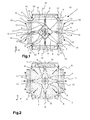
- Figure 1 shows a micro rate of rotation sensor 1 of the present invention in plan view, as a sketch.
- the sensor 1 is attached to a substrate beneath the sensor 1 by means of a central anchor 2.
- the sensor 1 is located at a slight distance in the Z-direction within the X-Y plane.
- a gimbal suspension 3 is disposed on the central anchor 2, by means of which the sensor 1 is rotationally displaceably suspended on the central anchor 2.
- the gimbal suspension 3 comprises anchor springs 4.
- Internal anchor springs 4 are aligned in the Y-direction and attach an inner ring 5 to the central anchor 2.
- Further anchor springs 4 aligned in the X-direction are disposed between the inner ring 5 and an outer ring 6.
- the anchor springs are torsional springs allowing rotation along the longitudinal axis thereof.
- the gimbal suspension 3 allows a rotary motion about the X-axis and about the Y-axis, due to the alignment of the corresponding anchor springs 4.
- Connecting springs 7 are disposed on the outer ring 6, to which X-Y sensor masses 8 are attached.
- the connecting springs 7 are attached on the outer ring 6, centered between the X-axis and the Y-axis, and allow motion of the X-Y sensor masses in the X-Y direction.
- the X-Y direction is centered between the X-Y axis at a 45° angle to the same.
- the X-Y sensor masses are thereby able to be displaced in said 45°direction in oscillation in the radial direction to the central anchor 2. Other angle directions are, of course, also possible.
- the connecting springs 7 are designed such that motion out of the X-Y plane is prevented.
- synchronization springs 9 are disposed between each two adjacent X-Y sensor masses 8. If the X-Y sensor masses 8 move away from the central anchor 2, then the synchronization springs 9 are extended. If the X-Y sensor masses 8 move back toward the central anchor 2, then the synchronization springs 9 are compressed. The extension and compression of the synchronization springs 9 is uniform, so that they ensure synchronous motion of the X-Y sensor masses 8 with respect to the central anchor 2.
- a total of two driving masses 11 and two Z sensor masses 12 are attached to the X-Y sensor masses 8 by means of connecting springs 10.
- Each of the driving masses 11 and the Z sensor masses 12 is, in turn, attached to two anchors 13 by means of further connecting springs 10.
- the driving masses 11 are displaceable substantially in the X-direction. In the present exemplary embodiment, they are further connected to the associated synchronization spring 9 facing the same by means of a connecting spring 10.
- the driving mass 1 further comprises drive elements, not shown, for example comb electrodes, of which one electrode is fixed to the substrate and the other electrode is connected to the driving mass 11.
- An applied alternating voltage causes the driving mass 11 to be driven to oscillate along the X-axis.
- the outer connecting springs 10' connecting the driving mass 11 to the anchors 13 are thereby implemented to be elastic within the X-Y plane. Said outer connecting spring 10' is not displaceable out of the X-Y plane.
- the driving mass 11 thus constantly remains in the X-Y plane.
- the displacement of the driving mass 1 in the direction of the X-axis causes the associated X-Y sensor masses 8 to be set in motion together with the driving mass 11.
- the attachment of the X-Y sensor masses 8 to the driving mass 11 by means of the connecting springs 10 and the synchronizing springs 9 and to each adjacent X-Y sensor mass 8 and the Z-sensor mass 12 generates a motion of the X-Y sensor mass 8 within the X-Y plane.
- the direction of motion is at an angle of about 45° between the X-axis and the Y-axis, corresponding to the support of the X-Y sensor mass 8 in the present exemplary embodiment.
- the actively driven driving mass 11 thus drives the X-Y sensor mass 8 in the X-Y direction.
- Two Z sensor masses 12 are provided between two driving masses 11 and parallel to the X-axis.
- the Z sensor masses 12 are connected to two adjacent X-Y sensor masses 8 by means of connecting springs 10.
- Each Z-sensor mass 12 is also connected to two anchors 13 by means of two outer connecting springs 10'.
- the outer connecting springs 10' allow motion of the Z-sensor mass substantially in the X-direction. Due to the design of the outer connecting spring 10', a slight motion in the Y-direction is to be expected. The substantial direction of motion, however, is in the direction of the X-axis. In any case, the Z-sensor mass also remains in the X-Y plane and does not move out of it.
- the drive motion of the sensor 1 is shown in Figure 2 . From this figure, it can be seen that the driving masses 11 move along the X-axis in the direction of the arrow. This causes the connecting springs 10 and the synchronization springs 9 to move the X-Y sensor mass 8 as well. The X-Y sensor mass 8 is thus driven indirectly. Even if it is fundamentally possible for the X-Y sensor mass 8 to also comprise dedicated drive elements, such as comb electrodes, this is not provided in an advantageous embodiment of the invention. Only the driving masses 11 are advantageously actively driven.
- the outer connecting springs 10' are contracted and the connecting springs 7 connecting the X-Y sensor masses 8 to the gimbal suspension 3 are extended.
- the X-Y sensor masses 8 move in a direction of about 45° from the X-axis and the Y-axis.
- the Z sensor masses 12 remain stationary. This applies to the case that the driving masses 11 move in antiphase. This means that they move simultaneously away from the central anchor 2 and back toward the same. In a different operating mode of the sensor 1, in contrast, it is also possible that the driving masses 11 move in phase.
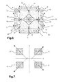
- FIG. 3 shows a plan view of the exemplary embodiment from Figure 1 , while a Z rate of rotation is detected by the sensor 1.
- the substrate of the sensor 1 rotates about the Z-axis. This causes the radially oscillating X-Y sensor masses to be deflected about the Z-axis. This takes place by a corresponding bending of the inner and outer anchor springs 4.
- connection of the X-Y sensor masses 8 to the Z sensor masses 12, by a corresponding rigidity of the connecting springs 10, causes the Z sensor masses 12 to be deflected substantially in the X-direction.
- Said deflection of the Z sensor masses 12 can change the distance thereof to each by means of sensor elements, not shown, such as electrodes, that are fixed to the substrate on one side and attached to the Z-sensor mass 12 on the other.
- Said changed electrical signal can be used for detecting the motion of the Z-sensor mass 12 in the X-direction, and thus for determining a Z rate of rotation.
- Figure 4 shows a section along the Y-axis of the sensor 1 from Figure 1 .
- the sensor 1 is detecting a rate of rotation about the Y-axis.
- a Coriolis force acts on the X-Y sensor masses 8 due to the oscillating driving masses 11 and X-Y sensor masses 8, causing the X-Y sensor masses 8 to rotate about the X-axis.
- This is possible due to the gimbal suspension 3, wherein the outer ring 6 moves out of the X-Y plane with respect to the inner ring 5.
- the connecting springs 10 that connect the X-Y sensor masses 8 to the driving masses 11 and the Z-sensor mass 12 also extend and thus allow motion of the X-Y sensor masses 8 out of the X-Y plane.
- Said tilting motion about the X-axis can be detected by means of sensor elements 21' and 21 ".
- the sensor element 21' is attached to the substrate 20, while the sensor element 21 " is attached to the X-Y sensor mass 8. Tilting the X-Y sensor masses 8 about the X-axis changes the spacing of the sensor elements 21' and 21 ", whereby the electrical signal of said plate electrodes changes.
- the tilting motion about the X-axis can be detected thereby and a conclusion can be drawn about a rate of rotation about the Y-direction.
- the Z sensor masses 12 do not move out of the original X-Y plane. Said masses remain in said X-Y plane due to the attachment thereof to the anchors 13 by means of the outer connecting springs 10'.
- FIG. 5 A section along the X-axis of the sensor 1 from Figure 1 is also shown in Figure 5 , wherein a rate of rotation occurs about the X-axis.
- the rate of rotation about the X-axis causes the X-Y sensor masses 8 to tilt about Y-axis.
- the driving masses 11 remain in the X-Y plane, as do the Z sensor masses, not shown. Only the X-Y sensor masses 8 tilt about the central anchor 2 and the Y-axis, together with the gimbal suspension 3, that is, with the anchor springs 4 and the inner and outer ring 5, 6.
- the spacing of the two plate electrodes of the sensor elements 21' and 21 " changes.
- This change can determine a rotation of the X-Y sensor masses 8 about the Y-axis and thus as an indicator for an X rate of rotation of the sensor 1.
- the synchronization springs 9 and the connecting springs 10 allow motion of the X-Y sensor masses 8 out of the X-Y plane.
- the connecting springs 10' in contrast, retain the driving mass 11 within the X-Y plane.
- FIG. 6 A further exemplary embodiment is shown in Figure 6 .
- the driving mass is thereby shown as a pair of driving masses.
- Each pair of driving masses is made of two individual driving masses 11'.
- Each of the driving masses 11' is connected to an anchor 13.
- the connection between each individual driving mass 11' and the X-Y sensor masses 8 uses connecting structures 22. Said arrangement makes deflection of the X-Y sensor elements 8 even easier.
- the spring positions and the dynamics of the entire structure can thereby be further optimized.
- the functionality is otherwise identical to that previously described.
- Figure 7 is a rough sketch of a further embodiment of the arrangement of X-Y sensor masses 8. Said representation is intended to clarify that the X-Y sensor masses 8 do not always have to be aligned to the origin of the X-axis, Y-axis, and Z-axis. The distances can also be increased, such that they approach each other outside of said center. The remaining structure is comparable to those of the previous figures.
- each X-Y sensor mass 8 comprises a dedicated anchor that is not disposed at said center.
- the design of the driving masses 11 and the Z sensor masses 12 is also not confined to the sketches shown here. The same applies to the X-Y sensor masses 8.
- the distribution and arrangement of the outer anchors 13 can also be done in a manner other than as shown here.
- the designs can also be such that one anchor is used as an anchor for two adjacent driving masses 11 and Z sensor masses 12, to which the two masses are attached. Fine-tuning of the springs can be used to influence the amplitudes of the motions of the individual masses.
- the type of motion of the individual masses can, of course, also be influenced by the arrangement and coupling of the individual masses to the corresponding springs.
Landscapes
- Physics & Mathematics (AREA)
- Engineering & Computer Science (AREA)
- General Physics & Mathematics (AREA)
- Radar, Positioning & Navigation (AREA)
- Remote Sensing (AREA)
- Gyroscopes (AREA)
- Micromachines (AREA)
- Pressure Sensors (AREA)
Applications Claiming Priority (1)
| Application Number | Priority Date | Filing Date | Title |
|---|---|---|---|
| DE201110057081 DE102011057081A1 (de) | 2011-12-28 | 2011-12-28 | Mikro-Drehratensensor und Verfahren zum Betreiben eines Mikro-Drehratensensors |
Publications (3)
| Publication Number | Publication Date |
|---|---|
| EP2610588A2 true EP2610588A2 (fr) | 2013-07-03 |
| EP2610588A3 EP2610588A3 (fr) | 2015-06-17 |
| EP2610588B1 EP2610588B1 (fr) | 2018-08-15 |
Family
ID=47594373
Family Applications (1)
| Application Number | Title | Priority Date | Filing Date |
|---|---|---|---|
| EP12197114.7A Active EP2610588B1 (fr) | 2011-12-28 | 2012-12-14 | Capteur de vitesse de rotation MEMS et procédé pour faire fonctionner un capteur de vitesse de rotation MEMS |
Country Status (6)
| Country | Link |
|---|---|
| US (2) | US9151611B2 (fr) |
| EP (1) | EP2610588B1 (fr) |
| JP (1) | JP6190586B2 (fr) |
| KR (1) | KR101964674B1 (fr) |
| CN (1) | CN103185575B (fr) |
| DE (1) | DE102011057081A1 (fr) |
Cited By (5)
| Publication number | Priority date | Publication date | Assignee | Title |
|---|---|---|---|---|
| WO2015114531A1 (fr) * | 2014-01-28 | 2015-08-06 | Murata Manufacturing Co., Ltd. | Structure de gyroscope et gyroscope améliorés |
| WO2020008157A3 (fr) * | 2018-07-06 | 2020-02-27 | Commissariat A L'energie Atomique Et Aux Energies Alternatives | Gyrometre micromecanique resonant performant a encombrement reduit |
| US11022439B2 (en) | 2018-12-19 | 2021-06-01 | Murata Manufacturing Co., Ltd. | Synchronized multi-axis gyroscope |
| US11415416B2 (en) | 2018-12-19 | 2022-08-16 | Murata Manufacturing Co., Ltd. | Vibration-robust multiaxis gyroscope |
| US11421991B2 (en) | 2017-11-09 | 2022-08-23 | Robert Bosch Gmbh | Yaw-rate sensor with a substrate having a main extension plane, method for manufacturing a yaw-rate sensor |
Families Citing this family (34)
| Publication number | Priority date | Publication date | Assignee | Title |
|---|---|---|---|---|
| IT1391972B1 (it) | 2008-11-26 | 2012-02-02 | St Microelectronics Rousset | Giroscopio microelettromeccanico con movimento di azionamento rotatorio e migliorate caratteristiche elettriche |
| IT1392741B1 (it) | 2008-12-23 | 2012-03-16 | St Microelectronics Rousset | Giroscopio microelettromeccanico con migliorata reiezione di disturbi di accelerazione |
| IT1394007B1 (it) | 2009-05-11 | 2012-05-17 | St Microelectronics Rousset | Struttura microelettromeccanica con reiezione migliorata di disturbi di accelerazione |
| ITTO20091042A1 (it) | 2009-12-24 | 2011-06-25 | St Microelectronics Srl | Giroscopio integrato microelettromeccanico con migliorata struttura di azionamento |
| ITTO20110806A1 (it) | 2011-09-12 | 2013-03-13 | St Microelectronics Srl | Dispositivo microelettromeccanico integrante un giroscopio e un accelerometro |
| DE102011057081A1 (de) * | 2011-12-28 | 2013-07-04 | Maxim Integrated Products, Inc. | Mikro-Drehratensensor und Verfahren zum Betreiben eines Mikro-Drehratensensors |
| DE102012200132A1 (de) * | 2012-01-05 | 2013-07-11 | Robert Bosch Gmbh | Drehratensensor und Verfahren zum Betrieb eines Drehratensensors |
| US9194704B2 (en) * | 2013-03-13 | 2015-11-24 | Freescale Semiconductor, Inc. | Angular rate sensor having multiple axis sensing capability |
| US9506756B2 (en) * | 2013-03-15 | 2016-11-29 | Freescale Semiconductor, Inc. | Multiple axis rate sensor |
| US9404747B2 (en) * | 2013-10-30 | 2016-08-02 | Stmicroelectroncs S.R.L. | Microelectromechanical gyroscope with compensation of quadrature error drift |
| FI126070B (en) * | 2014-01-28 | 2016-06-15 | Murata Manufacturing Co | Improved ring gyroscope structure and gyroscope |
| CN105043370B (zh) * | 2014-04-29 | 2019-01-22 | 财团法人工业技术研究院 | 具有支点元件的微型电机装置 |
| JP6575129B2 (ja) * | 2014-06-12 | 2019-09-18 | 株式会社デンソー | 振動型角速度センサ |
| US10247554B2 (en) * | 2014-09-24 | 2019-04-02 | The Regents Of The University Of California | Fully balanced micro-machined inertial sensor |
| JP2016085134A (ja) * | 2014-10-27 | 2016-05-19 | 株式会社デンソー | 振動型角速度センサ |
| FI127203B (en) * | 2015-05-15 | 2018-01-31 | Murata Manufacturing Co | Vibrating micromechanical sensor for angular velocity |
| DE102015213465A1 (de) * | 2015-07-17 | 2017-01-19 | Robert Bosch Gmbh | Mehrachsiger Drehratensensor mit geteiltem zentralem Rotor |
| CN106871886B (zh) * | 2015-12-10 | 2020-02-18 | 上海矽睿科技有限公司 | 振动模块以及陀螺仪 |
| ITUA20162172A1 (it) * | 2016-03-31 | 2017-10-01 | St Microelectronics Srl | Sensore accelerometrico realizzato in tecnologia mems avente elevata accuratezza e ridotta sensibilita' nei confronti della temperatura e dell'invecchiamento |
| US10696541B2 (en) | 2016-05-26 | 2020-06-30 | Honeywell International Inc. | Systems and methods for bias suppression in a non-degenerate MEMS sensor |
| US10371521B2 (en) * | 2016-05-26 | 2019-08-06 | Honeywell International Inc. | Systems and methods for a four-mass vibrating MEMS structure |
| US20190227493A1 (en) * | 2016-07-06 | 2019-07-25 | Ecole Polytechnique Federale De Lausanne (Epfl) | General 2 Degree of Freedom Isotropic Harmonic Oscillator and Associated Time Base Without Escapement or with Simplified Escapement |
| CN107328402B (zh) * | 2017-07-12 | 2022-06-24 | 深迪半导体(绍兴)有限公司 | 一种三轴mems陀螺仪 |
| CN107192384B (zh) * | 2017-07-24 | 2022-04-05 | 深迪半导体(绍兴)有限公司 | 一种mems三轴陀螺仪 |
| DE102017213644A1 (de) * | 2017-08-07 | 2019-02-07 | Robert Bosch Gmbh | Drehratensensor, Verfahren zur Herstellung eines Drehratensensors |
| JP6741113B2 (ja) * | 2018-05-08 | 2020-08-19 | 株式会社村田製作所 | ジャイロスコープのための同期構造 |
| KR102111568B1 (ko) * | 2019-02-12 | 2020-05-18 | 주식회사 신성씨앤티 | 통합 3축 멤스 자이로스코프 |
| JP6879391B2 (ja) * | 2019-02-15 | 2021-06-02 | 株式会社村田製作所 | 同期フレームを有する多軸ジャイロスコープ |
| US11680797B2 (en) * | 2019-03-27 | 2023-06-20 | Panasonic Intellectual Property Management Co., Ltd. | Physical quantity sensor |
| US11891297B2 (en) * | 2019-07-05 | 2024-02-06 | Aac Acoustic Technologies (Shenzhen) Co., Ltd. | Motion control structure and actuator |
| JP7188311B2 (ja) | 2019-07-31 | 2022-12-13 | セイコーエプソン株式会社 | ジャイロセンサー、電子機器、及び移動体 |
| IT201900017546A1 (it) | 2019-09-30 | 2021-03-30 | St Microelectronics Srl | Dispositivo a pulsante mems resistente all'acqua, dispositivo di ingresso comprendente il dispositivo a pulsante mems e apparecchio elettronico |
| CN114719835B (zh) | 2022-02-22 | 2024-07-16 | 瑞声开泰科技(武汉)有限公司 | 微机械陀螺仪及电子产品 |
| CN114719833A (zh) * | 2022-02-22 | 2022-07-08 | 瑞声开泰科技(武汉)有限公司 | 一种mems陀螺 |
Citations (1)
| Publication number | Priority date | Publication date | Assignee | Title |
|---|---|---|---|---|
| US6308567B1 (en) | 1998-12-10 | 2001-10-30 | Denso Corporation | Angular velocity sensor |
Family Cites Families (31)
| Publication number | Priority date | Publication date | Assignee | Title |
|---|---|---|---|---|
| US5767405A (en) * | 1992-04-07 | 1998-06-16 | The Charles Stark Draper Laboratory, Inc. | Comb-drive micromechanical tuning fork gyroscope with piezoelectric readout |
| US5955668A (en) * | 1997-01-28 | 1999-09-21 | Irvine Sensors Corporation | Multi-element micro gyro |
| JP4353087B2 (ja) * | 2004-12-01 | 2009-10-28 | 株式会社デンソー | 回転振動型角速度センサ |
| JP4887034B2 (ja) * | 2005-12-05 | 2012-02-29 | 日立オートモティブシステムズ株式会社 | 慣性センサ |
| EP1832841B1 (fr) | 2006-03-10 | 2015-12-30 | STMicroelectronics Srl | Structure de capteur intégré microélectromécanique avec déplacement de commande rotative |
| DE102007057042A1 (de) * | 2007-09-10 | 2009-03-12 | Continental Teves Ag & Co. Ohg | Mikromechanischer Drehratensensor mit Kopplungsbalken und Aufhängungs-Federelementen zur Unterdrückung der Quadratur |
| US8042396B2 (en) * | 2007-09-11 | 2011-10-25 | Stmicroelectronics S.R.L. | Microelectromechanical sensor with improved mechanical decoupling of sensing and driving modes |
| DE102007054505B4 (de) * | 2007-11-15 | 2016-12-22 | Robert Bosch Gmbh | Drehratensensor |
| JP4508230B2 (ja) * | 2007-11-21 | 2010-07-21 | ソニー株式会社 | 慣性センサ及びその検出装置 |
| WO2009078284A1 (fr) * | 2007-12-19 | 2009-06-25 | Murata Manufacturing Co., Ltd. | Capteur de vitesse angulaire |
| CN101910789B (zh) | 2008-01-07 | 2012-02-29 | 株式会社村田制作所 | 角速度传感器 |
| DE102008002748A1 (de) * | 2008-06-27 | 2009-12-31 | Sensordynamics Ag | Mikro-Gyroskop |
| IT1391972B1 (it) * | 2008-11-26 | 2012-02-02 | St Microelectronics Rousset | Giroscopio microelettromeccanico con movimento di azionamento rotatorio e migliorate caratteristiche elettriche |
| ITTO20090489A1 (it) * | 2008-11-26 | 2010-12-27 | St Microelectronics Srl | Circuito di lettura per un giroscopio mems multi-asse avente direzioni di rilevamento inclinate rispetto agli assi di riferimento, e corrispondente giroscopio mems multi-asse |
| IT1391973B1 (it) * | 2008-11-26 | 2012-02-02 | St Microelectronics Rousset | Giroscopio microelettromeccanico mono o biassiale con aumentata sensibilita' al rilevamento di velocita' angolari |
| DE102009001248B4 (de) * | 2009-02-27 | 2020-12-17 | Hanking Electronics, Ltd. | MEMS-Gyroskop zur Ermittlung von Rotationsbewegungen um eine x-, y- oder z-Achse |
| DE102009001244A1 (de) * | 2009-02-27 | 2010-09-02 | Sensordynamics Ag | Mikro-Gyroskop zur Ermittlung von Rotationsbewegungen um eine x-, y- oder z-Achse |
| JP2010210407A (ja) * | 2009-03-10 | 2010-09-24 | Murata Mfg Co Ltd | 角速度センサ |
| US8256290B2 (en) * | 2009-03-17 | 2012-09-04 | Minyao Mao | Tri-axis angular rate sensor |
| DE102009001922A1 (de) * | 2009-03-26 | 2010-09-30 | Sensordynamics Ag | Mikro-Gyroskop zur Ermittlung von Rotationsbewegungen um drei senkrecht aufeinanderstehende Raumachsen x, y und z |
| FR2945621B1 (fr) * | 2009-05-15 | 2011-08-26 | Commissariat Energie Atomique | Structure de couplage pour gyrometre resonnant |
| DE102009026511A1 (de) * | 2009-05-27 | 2010-12-02 | Sensordynamics Ag | Mikro-Gyroskop zur Ermittlung von Rotationsbewegungen um mindestens eine von drei senkrecht aufeinanderstehenden Raumachsen |
| US8739626B2 (en) * | 2009-08-04 | 2014-06-03 | Fairchild Semiconductor Corporation | Micromachined inertial sensor devices |
| US8534127B2 (en) * | 2009-09-11 | 2013-09-17 | Invensense, Inc. | Extension-mode angular velocity sensor |
| IT1397594B1 (it) * | 2009-12-21 | 2013-01-16 | St Microelectronics Rousset | Giroscopio microelettromeccanico con funzione di auto-test continua e metodo di controllo di un giroscopio microelettromeccanico. |
| ITTO20091042A1 (it) * | 2009-12-24 | 2011-06-25 | St Microelectronics Srl | Giroscopio integrato microelettromeccanico con migliorata struttura di azionamento |
| DE102010028005A1 (de) * | 2010-04-20 | 2011-10-20 | Sensordynamics Ag | Mikro-Gyroskop zur Ermittlung von Bewegungen |
| CN103221779B (zh) * | 2010-09-18 | 2017-05-31 | 快捷半导体公司 | 微机械整体式六轴惯性传感器 |
| US9003882B1 (en) * | 2010-11-03 | 2015-04-14 | Georgia Tech Research Corporation | Vibratory tuning fork based six-degrees of freedom inertial measurement MEMS device |
| DE102011057081A1 (de) * | 2011-12-28 | 2013-07-04 | Maxim Integrated Products, Inc. | Mikro-Drehratensensor und Verfahren zum Betreiben eines Mikro-Drehratensensors |
| US20130239679A1 (en) * | 2012-03-13 | 2013-09-19 | Pavel Kornilovich | Three-axis gyroscope |
-
2011
- 2011-12-28 DE DE201110057081 patent/DE102011057081A1/de not_active Withdrawn
-
2012
- 2012-12-14 EP EP12197114.7A patent/EP2610588B1/fr active Active
- 2012-12-19 US US13/720,426 patent/US9151611B2/en active Active
- 2012-12-20 JP JP2012277869A patent/JP6190586B2/ja active Active
- 2012-12-26 KR KR1020120153107A patent/KR101964674B1/ko active IP Right Grant
- 2012-12-28 CN CN201210584984.3A patent/CN103185575B/zh active Active
-
2015
- 2015-10-05 US US14/875,379 patent/US9784580B2/en active Active
Patent Citations (1)
| Publication number | Priority date | Publication date | Assignee | Title |
|---|---|---|---|---|
| US6308567B1 (en) | 1998-12-10 | 2001-10-30 | Denso Corporation | Angular velocity sensor |
Cited By (8)
| Publication number | Priority date | Publication date | Assignee | Title |
|---|---|---|---|---|
| WO2015114531A1 (fr) * | 2014-01-28 | 2015-08-06 | Murata Manufacturing Co., Ltd. | Structure de gyroscope et gyroscope améliorés |
| US9551577B2 (en) | 2014-01-28 | 2017-01-24 | Murata Manufacturing Co., Ltd. | Gyroscope structure and gyroscope |
| EP3367060A1 (fr) * | 2014-01-28 | 2018-08-29 | Murata Manufacturing Co., Ltd. | Structure de gyroscope amélioré et gyroscope |
| US10365103B2 (en) | 2014-01-28 | 2019-07-30 | Murata Manufacturing Co., Ltd. | Gyroscope structure and gyroscope |
| US11421991B2 (en) | 2017-11-09 | 2022-08-23 | Robert Bosch Gmbh | Yaw-rate sensor with a substrate having a main extension plane, method for manufacturing a yaw-rate sensor |
| WO2020008157A3 (fr) * | 2018-07-06 | 2020-02-27 | Commissariat A L'energie Atomique Et Aux Energies Alternatives | Gyrometre micromecanique resonant performant a encombrement reduit |
| US11022439B2 (en) | 2018-12-19 | 2021-06-01 | Murata Manufacturing Co., Ltd. | Synchronized multi-axis gyroscope |
| US11415416B2 (en) | 2018-12-19 | 2022-08-16 | Murata Manufacturing Co., Ltd. | Vibration-robust multiaxis gyroscope |
Also Published As
| Publication number | Publication date |
|---|---|
| KR101964674B1 (ko) | 2019-04-02 |
| CN103185575A (zh) | 2013-07-03 |
| KR20130076741A (ko) | 2013-07-08 |
| EP2610588A3 (fr) | 2015-06-17 |
| DE102011057081A1 (de) | 2013-07-04 |
| CN103185575B (zh) | 2017-10-03 |
| US9151611B2 (en) | 2015-10-06 |
| US20160033275A1 (en) | 2016-02-04 |
| EP2610588B1 (fr) | 2018-08-15 |
| JP2013145231A (ja) | 2013-07-25 |
| JP6190586B2 (ja) | 2017-08-30 |
| US9784580B2 (en) | 2017-10-10 |
| US20130167636A1 (en) | 2013-07-04 |
Similar Documents
| Publication | Publication Date | Title |
|---|---|---|
| US9784580B2 (en) | Micro rate of rotation sensor and method for operating a micro rate of rotation sensor | |
| US8479575B2 (en) | Microgyroscope for determining rotational movements about an X and/or Y and Z axis | |
| US9909873B2 (en) | MEMS gyroscope for determining rotational movements about an x, y, and/or z axis | |
| US9857175B2 (en) | Micro-gyroscope for detecting motions | |
| US8776599B2 (en) | Micro gyroscope for determining rotational movements about three spatial axes which are perpendicular to one another | |
| US9664515B2 (en) | MEMS sensors and methods for detecting rotation rates | |
| US10024663B2 (en) | Micromechanical coriolis rate of rotation sensor | |
| CN116147600A (zh) | 微机电多轴角速度感测器 |
Legal Events
| Date | Code | Title | Description |
|---|---|---|---|
| PUAI | Public reference made under article 153(3) epc to a published international application that has entered the european phase |
Free format text: ORIGINAL CODE: 0009012 |
|
| AK | Designated contracting states |
Kind code of ref document: A2 Designated state(s): AL AT BE BG CH CY CZ DE DK EE ES FI FR GB GR HR HU IE IS IT LI LT LU LV MC MK MT NL NO PL PT RO RS SE SI SK SM TR |
|
| AX | Request for extension of the european patent |
Extension state: BA ME |
|
| PUAL | Search report despatched |
Free format text: ORIGINAL CODE: 0009013 |
|
| AK | Designated contracting states |
Kind code of ref document: A3 Designated state(s): AL AT BE BG CH CY CZ DE DK EE ES FI FR GB GR HR HU IE IS IT LI LT LU LV MC MK MT NL NO PL PT RO RS SE SI SK SM TR |
|
| AX | Request for extension of the european patent |
Extension state: BA ME |
|
| RIC1 | Information provided on ipc code assigned before grant |
Ipc: G01C 19/5747 20120101AFI20150512BHEP |
|
| 17P | Request for examination filed |
Effective date: 20151205 |
|
| RBV | Designated contracting states (corrected) |
Designated state(s): AL AT BE BG CH CY CZ DE DK EE ES FI FR GB GR HR HU IE IS IT LI LT LU LV MC MK MT NL NO PL PT RO RS SE SI SK SM TR |
|
| GRAP | Despatch of communication of intention to grant a patent |
Free format text: ORIGINAL CODE: EPIDOSNIGR1 |
|
| INTG | Intention to grant announced |
Effective date: 20180503 |
|
| GRAS | Grant fee paid |
Free format text: ORIGINAL CODE: EPIDOSNIGR3 |
|
| GRAA | (expected) grant |
Free format text: ORIGINAL CODE: 0009210 |
|
| AK | Designated contracting states |
Kind code of ref document: B1 Designated state(s): AL AT BE BG CH CY CZ DE DK EE ES FI FR GB GR HR HU IE IS IT LI LT LU LV MC MK MT NL NO PL PT RO RS SE SI SK SM TR |
|
| RAP1 | Party data changed (applicant data changed or rights of an application transferred) |
Owner name: HANKING ELECTRONICS, LTD. |
|
| REG | Reference to a national code |
Ref country code: CH Ref legal event code: EP Ref country code: GB Ref legal event code: FG4D Ref country code: AT Ref legal event code: REF Ref document number: 1030305 Country of ref document: AT Kind code of ref document: T Effective date: 20180815 |
|
| REG | Reference to a national code |
Ref country code: IE Ref legal event code: FG4D |
|
| REG | Reference to a national code |
Ref country code: DE Ref legal event code: R096 Ref document number: 602012049747 Country of ref document: DE |
|
| REG | Reference to a national code |
Ref country code: NL Ref legal event code: MP Effective date: 20180815 |
|
| REG | Reference to a national code |
Ref country code: LT Ref legal event code: MG4D |
|
| REG | Reference to a national code |
Ref country code: AT Ref legal event code: MK05 Ref document number: 1030305 Country of ref document: AT Kind code of ref document: T Effective date: 20180815 |
|
| PG25 | Lapsed in a contracting state [announced via postgrant information from national office to epo] |
Ref country code: LT Free format text: LAPSE BECAUSE OF FAILURE TO SUBMIT A TRANSLATION OF THE DESCRIPTION OR TO PAY THE FEE WITHIN THE PRESCRIBED TIME-LIMIT Effective date: 20180815 Ref country code: BG Free format text: LAPSE BECAUSE OF FAILURE TO SUBMIT A TRANSLATION OF THE DESCRIPTION OR TO PAY THE FEE WITHIN THE PRESCRIBED TIME-LIMIT Effective date: 20181115 Ref country code: NL Free format text: LAPSE BECAUSE OF FAILURE TO SUBMIT A TRANSLATION OF THE DESCRIPTION OR TO PAY THE FEE WITHIN THE PRESCRIBED TIME-LIMIT Effective date: 20180815 Ref country code: NO Free format text: LAPSE BECAUSE OF FAILURE TO SUBMIT A TRANSLATION OF THE DESCRIPTION OR TO PAY THE FEE WITHIN THE PRESCRIBED TIME-LIMIT Effective date: 20181115 Ref country code: SE Free format text: LAPSE BECAUSE OF FAILURE TO SUBMIT A TRANSLATION OF THE DESCRIPTION OR TO PAY THE FEE WITHIN THE PRESCRIBED TIME-LIMIT Effective date: 20180815 Ref country code: GR Free format text: LAPSE BECAUSE OF FAILURE TO SUBMIT A TRANSLATION OF THE DESCRIPTION OR TO PAY THE FEE WITHIN THE PRESCRIBED TIME-LIMIT Effective date: 20181116 Ref country code: AT Free format text: LAPSE BECAUSE OF FAILURE TO SUBMIT A TRANSLATION OF THE DESCRIPTION OR TO PAY THE FEE WITHIN THE PRESCRIBED TIME-LIMIT Effective date: 20180815 Ref country code: IS Free format text: LAPSE BECAUSE OF FAILURE TO SUBMIT A TRANSLATION OF THE DESCRIPTION OR TO PAY THE FEE WITHIN THE PRESCRIBED TIME-LIMIT Effective date: 20181215 Ref country code: RS Free format text: LAPSE BECAUSE OF FAILURE TO SUBMIT A TRANSLATION OF THE DESCRIPTION OR TO PAY THE FEE WITHIN THE PRESCRIBED TIME-LIMIT Effective date: 20180815 Ref country code: FI Free format text: LAPSE BECAUSE OF FAILURE TO SUBMIT A TRANSLATION OF THE DESCRIPTION OR TO PAY THE FEE WITHIN THE PRESCRIBED TIME-LIMIT Effective date: 20180815 |
|
| PG25 | Lapsed in a contracting state [announced via postgrant information from national office to epo] |
Ref country code: LV Free format text: LAPSE BECAUSE OF FAILURE TO SUBMIT A TRANSLATION OF THE DESCRIPTION OR TO PAY THE FEE WITHIN THE PRESCRIBED TIME-LIMIT Effective date: 20180815 Ref country code: AL Free format text: LAPSE BECAUSE OF FAILURE TO SUBMIT A TRANSLATION OF THE DESCRIPTION OR TO PAY THE FEE WITHIN THE PRESCRIBED TIME-LIMIT Effective date: 20180815 Ref country code: HR Free format text: LAPSE BECAUSE OF FAILURE TO SUBMIT A TRANSLATION OF THE DESCRIPTION OR TO PAY THE FEE WITHIN THE PRESCRIBED TIME-LIMIT Effective date: 20180815 |
|
| PG25 | Lapsed in a contracting state [announced via postgrant information from national office to epo] |
Ref country code: EE Free format text: LAPSE BECAUSE OF FAILURE TO SUBMIT A TRANSLATION OF THE DESCRIPTION OR TO PAY THE FEE WITHIN THE PRESCRIBED TIME-LIMIT Effective date: 20180815 Ref country code: PL Free format text: LAPSE BECAUSE OF FAILURE TO SUBMIT A TRANSLATION OF THE DESCRIPTION OR TO PAY THE FEE WITHIN THE PRESCRIBED TIME-LIMIT Effective date: 20180815 Ref country code: CZ Free format text: LAPSE BECAUSE OF FAILURE TO SUBMIT A TRANSLATION OF THE DESCRIPTION OR TO PAY THE FEE WITHIN THE PRESCRIBED TIME-LIMIT Effective date: 20180815 Ref country code: RO Free format text: LAPSE BECAUSE OF FAILURE TO SUBMIT A TRANSLATION OF THE DESCRIPTION OR TO PAY THE FEE WITHIN THE PRESCRIBED TIME-LIMIT Effective date: 20180815 Ref country code: ES Free format text: LAPSE BECAUSE OF FAILURE TO SUBMIT A TRANSLATION OF THE DESCRIPTION OR TO PAY THE FEE WITHIN THE PRESCRIBED TIME-LIMIT Effective date: 20180815 |
|
| REG | Reference to a national code |
Ref country code: DE Ref legal event code: R097 Ref document number: 602012049747 Country of ref document: DE |
|
| PG25 | Lapsed in a contracting state [announced via postgrant information from national office to epo] |
Ref country code: DK Free format text: LAPSE BECAUSE OF FAILURE TO SUBMIT A TRANSLATION OF THE DESCRIPTION OR TO PAY THE FEE WITHIN THE PRESCRIBED TIME-LIMIT Effective date: 20180815 Ref country code: SM Free format text: LAPSE BECAUSE OF FAILURE TO SUBMIT A TRANSLATION OF THE DESCRIPTION OR TO PAY THE FEE WITHIN THE PRESCRIBED TIME-LIMIT Effective date: 20180815 Ref country code: SK Free format text: LAPSE BECAUSE OF FAILURE TO SUBMIT A TRANSLATION OF THE DESCRIPTION OR TO PAY THE FEE WITHIN THE PRESCRIBED TIME-LIMIT Effective date: 20180815 |
|
| PLBE | No opposition filed within time limit |
Free format text: ORIGINAL CODE: 0009261 |
|
| STAA | Information on the status of an ep patent application or granted ep patent |
Free format text: STATUS: NO OPPOSITION FILED WITHIN TIME LIMIT |
|
| REG | Reference to a national code |
Ref country code: DE Ref legal event code: R119 Ref document number: 602012049747 Country of ref document: DE |
|
| 26N | No opposition filed |
Effective date: 20190516 |
|
| REG | Reference to a national code |
Ref country code: CH Ref legal event code: PL |
|
| GBPC | Gb: european patent ceased through non-payment of renewal fee |
Effective date: 20181214 |
|
| PG25 | Lapsed in a contracting state [announced via postgrant information from national office to epo] |
Ref country code: LU Free format text: LAPSE BECAUSE OF NON-PAYMENT OF DUE FEES Effective date: 20181214 Ref country code: MC Free format text: LAPSE BECAUSE OF FAILURE TO SUBMIT A TRANSLATION OF THE DESCRIPTION OR TO PAY THE FEE WITHIN THE PRESCRIBED TIME-LIMIT Effective date: 20180815 Ref country code: SI Free format text: LAPSE BECAUSE OF FAILURE TO SUBMIT A TRANSLATION OF THE DESCRIPTION OR TO PAY THE FEE WITHIN THE PRESCRIBED TIME-LIMIT Effective date: 20180815 |
|
| REG | Reference to a national code |
Ref country code: IE Ref legal event code: MM4A |
|
| REG | Reference to a national code |
Ref country code: BE Ref legal event code: MM Effective date: 20181231 |
|
| PG25 | Lapsed in a contracting state [announced via postgrant information from national office to epo] |
Ref country code: IE Free format text: LAPSE BECAUSE OF NON-PAYMENT OF DUE FEES Effective date: 20181214 Ref country code: DE Free format text: LAPSE BECAUSE OF NON-PAYMENT OF DUE FEES Effective date: 20190702 Ref country code: FR Free format text: LAPSE BECAUSE OF NON-PAYMENT OF DUE FEES Effective date: 20181231 |
|
| PG25 | Lapsed in a contracting state [announced via postgrant information from national office to epo] |
Ref country code: BE Free format text: LAPSE BECAUSE OF NON-PAYMENT OF DUE FEES Effective date: 20181231 |
|
| PG25 | Lapsed in a contracting state [announced via postgrant information from national office to epo] |
Ref country code: CH Free format text: LAPSE BECAUSE OF NON-PAYMENT OF DUE FEES Effective date: 20181231 Ref country code: GB Free format text: LAPSE BECAUSE OF NON-PAYMENT OF DUE FEES Effective date: 20181214 Ref country code: LI Free format text: LAPSE BECAUSE OF NON-PAYMENT OF DUE FEES Effective date: 20181231 |
|
| PG25 | Lapsed in a contracting state [announced via postgrant information from national office to epo] |
Ref country code: MT Free format text: LAPSE BECAUSE OF NON-PAYMENT OF DUE FEES Effective date: 20181214 |
|
| PG25 | Lapsed in a contracting state [announced via postgrant information from national office to epo] |
Ref country code: TR Free format text: LAPSE BECAUSE OF FAILURE TO SUBMIT A TRANSLATION OF THE DESCRIPTION OR TO PAY THE FEE WITHIN THE PRESCRIBED TIME-LIMIT Effective date: 20180815 |
|
| PG25 | Lapsed in a contracting state [announced via postgrant information from national office to epo] |
Ref country code: PT Free format text: LAPSE BECAUSE OF FAILURE TO SUBMIT A TRANSLATION OF THE DESCRIPTION OR TO PAY THE FEE WITHIN THE PRESCRIBED TIME-LIMIT Effective date: 20180815 |
|
| PG25 | Lapsed in a contracting state [announced via postgrant information from national office to epo] |
Ref country code: HU Free format text: LAPSE BECAUSE OF FAILURE TO SUBMIT A TRANSLATION OF THE DESCRIPTION OR TO PAY THE FEE WITHIN THE PRESCRIBED TIME-LIMIT; INVALID AB INITIO Effective date: 20121214 Ref country code: CY Free format text: LAPSE BECAUSE OF FAILURE TO SUBMIT A TRANSLATION OF THE DESCRIPTION OR TO PAY THE FEE WITHIN THE PRESCRIBED TIME-LIMIT Effective date: 20180815 Ref country code: MK Free format text: LAPSE BECAUSE OF NON-PAYMENT OF DUE FEES Effective date: 20180815 |
|
| PGFP | Annual fee paid to national office [announced via postgrant information from national office to epo] |
Ref country code: IT Payment date: 20230629 Year of fee payment: 11 |