EP2610050A2 - Kissen-Airbag mit vorbestimmter Öffnung in einem Luftzylinder-Faltbereich und Herstellung davon - Google Patents
Kissen-Airbag mit vorbestimmter Öffnung in einem Luftzylinder-Faltbereich und Herstellung davon Download PDFInfo
- Publication number
- EP2610050A2 EP2610050A2 EP12177446.7A EP12177446A EP2610050A2 EP 2610050 A2 EP2610050 A2 EP 2610050A2 EP 12177446 A EP12177446 A EP 12177446A EP 2610050 A2 EP2610050 A2 EP 2610050A2
- Authority
- EP
- European Patent Office
- Prior art keywords
- heat sealing
- air
- air cylinder
- turning
- lateral
- Prior art date
- Legal status (The legal status is an assumption and is not a legal conclusion. Google has not performed a legal analysis and makes no representation as to the accuracy of the status listed.)
- Granted
Links
Images


Classifications
-
- B—PERFORMING OPERATIONS; TRANSPORTING
- B31—MAKING ARTICLES OF PAPER, CARDBOARD OR MATERIAL WORKED IN A MANNER ANALOGOUS TO PAPER; WORKING PAPER, CARDBOARD OR MATERIAL WORKED IN A MANNER ANALOGOUS TO PAPER
- B31D—MAKING ARTICLES OF PAPER, CARDBOARD OR MATERIAL WORKED IN A MANNER ANALOGOUS TO PAPER, NOT PROVIDED FOR IN SUBCLASSES B31B OR B31C
- B31D5/00—Multiple-step processes for making three-dimensional articles ; Making three-dimensional articles
- B31D5/0039—Multiple-step processes for making three-dimensional articles ; Making three-dimensional articles for making dunnage or cushion pads
- B31D5/0073—Multiple-step processes for making three-dimensional articles ; Making three-dimensional articles for making dunnage or cushion pads including pillow forming
-
- B—PERFORMING OPERATIONS; TRANSPORTING
- B65—CONVEYING; PACKING; STORING; HANDLING THIN OR FILAMENTARY MATERIAL
- B65D—CONTAINERS FOR STORAGE OR TRANSPORT OF ARTICLES OR MATERIALS, e.g. BAGS, BARRELS, BOTTLES, BOXES, CANS, CARTONS, CRATES, DRUMS, JARS, TANKS, HOPPERS, FORWARDING CONTAINERS; ACCESSORIES, CLOSURES, OR FITTINGS THEREFOR; PACKAGING ELEMENTS; PACKAGES
- B65D81/00—Containers, packaging elements, or packages, for contents presenting particular transport or storage problems, or adapted to be used for non-packaging purposes after removal of contents
- B65D81/02—Containers, packaging elements, or packages, for contents presenting particular transport or storage problems, or adapted to be used for non-packaging purposes after removal of contents specially adapted to protect contents from mechanical damage
- B65D81/03—Wrappers or envelopes with shock-absorbing properties, e.g. bubble films
-
- B—PERFORMING OPERATIONS; TRANSPORTING
- B31—MAKING ARTICLES OF PAPER, CARDBOARD OR MATERIAL WORKED IN A MANNER ANALOGOUS TO PAPER; WORKING PAPER, CARDBOARD OR MATERIAL WORKED IN A MANNER ANALOGOUS TO PAPER
- B31D—MAKING ARTICLES OF PAPER, CARDBOARD OR MATERIAL WORKED IN A MANNER ANALOGOUS TO PAPER, NOT PROVIDED FOR IN SUBCLASSES B31B OR B31C
- B31D2205/00—Multiple-step processes for making three-dimensional articles
- B31D2205/0005—Multiple-step processes for making three-dimensional articles for making dunnage or cushion pads
- B31D2205/0011—Multiple-step processes for making three-dimensional articles for making dunnage or cushion pads including particular additional operations
- B31D2205/0047—Feeding, guiding or shaping the material
-
- B—PERFORMING OPERATIONS; TRANSPORTING
- B31—MAKING ARTICLES OF PAPER, CARDBOARD OR MATERIAL WORKED IN A MANNER ANALOGOUS TO PAPER; WORKING PAPER, CARDBOARD OR MATERIAL WORKED IN A MANNER ANALOGOUS TO PAPER
- B31D—MAKING ARTICLES OF PAPER, CARDBOARD OR MATERIAL WORKED IN A MANNER ANALOGOUS TO PAPER, NOT PROVIDED FOR IN SUBCLASSES B31B OR B31C
- B31D2205/00—Multiple-step processes for making three-dimensional articles
- B31D2205/0005—Multiple-step processes for making three-dimensional articles for making dunnage or cushion pads
- B31D2205/0011—Multiple-step processes for making three-dimensional articles for making dunnage or cushion pads including particular additional operations
- B31D2205/0064—Stabilizing the shape of the final product, e.g. by mechanical interlocking
-
- B—PERFORMING OPERATIONS; TRANSPORTING
- B65—CONVEYING; PACKING; STORING; HANDLING THIN OR FILAMENTARY MATERIAL
- B65D—CONTAINERS FOR STORAGE OR TRANSPORT OF ARTICLES OR MATERIALS, e.g. BAGS, BARRELS, BOTTLES, BOXES, CANS, CARTONS, CRATES, DRUMS, JARS, TANKS, HOPPERS, FORWARDING CONTAINERS; ACCESSORIES, CLOSURES, OR FITTINGS THEREFOR; PACKAGING ELEMENTS; PACKAGES
- B65D31/00—Bags or like containers made of paper and having structural provision for thickness of contents
- B65D31/14—Valve bags, i.e. with valves for filling
-
- Y—GENERAL TAGGING OF NEW TECHNOLOGICAL DEVELOPMENTS; GENERAL TAGGING OF CROSS-SECTIONAL TECHNOLOGIES SPANNING OVER SEVERAL SECTIONS OF THE IPC; TECHNICAL SUBJECTS COVERED BY FORMER USPC CROSS-REFERENCE ART COLLECTIONS [XRACs] AND DIGESTS
- Y10—TECHNICAL SUBJECTS COVERED BY FORMER USPC
- Y10T—TECHNICAL SUBJECTS COVERED BY FORMER US CLASSIFICATION
- Y10T428/00—Stock material or miscellaneous articles
- Y10T428/13—Hollow or container type article [e.g., tube, vase, etc.]
- Y10T428/1334—Nonself-supporting tubular film or bag [e.g., pouch, envelope, packet, etc.]
Definitions
- the present invention relates to an air cylinder bag structure, and more Specifically to a cushioning air bag with a predetermined opening in an air cylinder turning zone and a method for making it.
- an air packing bag which is heat-sealed to form airtight air cylinders, and configured with air filling entrances allowing air filling; the air packing bag can be used as a cushioning material in interior packaging after air is filled in the air cylinders through the air filling entrances.
- the present invention proposes a cushioning air bag with a predetermined opening in an air cylinder turning zone, including: an air cylinder sheet, constituted by a plurality of air cylinders formed by adhering two sheets of outer film with a plurality of longitudinal heat sealing lines and a plurality of transversal heat sealing lines; a plurality of turning points, formed on the plurality of air cylinders or the plurality of longitudinal heat sealing lines by adhering the two sheets of outer film; a turning middle line, position on the air cylinder sheet, parallel substantially to the plurality of transversal heat sealing lines; a plurality of nodes, positioned on two respective sides of the turning middle line, and at a predetermined distance from the turning middle line; and a plurality of lateral heat sealing lines, used to stick two sides of the turned air cylinder sheet after the air cylinder is turned along the turning middle line, wherein, the plurality of lateral heat sealing lines are extended from two respective ends of the air cylinder sheets to the corresponding plurality of nodes,
- the present invention also proposes a method for making a cushioning air bag with a predetermined opening in an air cylinder turning zone, including: providing an air cylinder sheet, constituted by a plurality of air cylinders formed by adhering two sheets of outer film with a plurality of longitudinal heat sealing lines and a plurality of transversal heat sealing lines; adhering the two sheets of outer film to form a plurality of turning points on the plurality of air cylinders or the plurality of longitudinal heat sealing lines; determining a turning middle line on the air cylinder sheet, parallel substantially to the plurality of transversal heat sealing lines; configuring a plurality of nodes on two respective sides of the turning middle line at a predetermined distance from the turning middle line; turning the air cylinder sheet along the turning middle line; and adhering two sides of the turned air cylinder sheet with a plurality of lateral heat sealing lines; wherein, the plurality of lateral heat sealing lines are extended from two respective ends of the air cylinder sheets to the corresponding plurality of nodes, two lateral
- the present invention eliminates pointed corners by presetting non-sealing sections in a lateral turning zone, and further utilizes a turning node zone being positioned at an air cylinder and a bottom air cylinder between the turning nodes, allowing an area change of the air cylinder to adjust a cushioning effect of the region.
- a volume of an outer box can be reduced, and air leaking of the air cylinder due to a crevice caused from pointed corner friction can be eliminated.
- Adjustment of an air cylinder around a triangle of the opening is used to fit a wrapped object, avoid pointed corners, and increase a cushioning effect.
- the bottom cushioning air cylinder structure eliminates perplexity of lateral side sealing of a bag body causing pointed corners due to air compression after the bottom air cylinder is filled with air, in the prior art. Additionally, the areas of the nodes of the lateral turning zone and the air cylinder at that portion can be increased and reduced by means of heat sealing, thereby strengthening a cushioning effect of the turning zone.
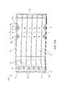
- FIGs. 1 and 2 illustrate a cushioning air bag in which an air cylinder turning zone is preset with an opening disclosed by the present invention.
- An air cylinder bag of the present invention includes a cylinder sheet 200, a plurality of longitudinal heat sealing lines 21, a plurality of transversal heat sealing lines 22, a plurality of turning points 4a, 4b, and a respective non-heat sealing section in a predetermined turning zone at the two sides of the bag and a predetermined reduced area required for air cylinders in the non-heat sealing section of a turning zone.
- the air cylinder sheet 200 is formed of two sheets of outer film 2 by means of heat sealing, and a plurality of hermetically sealed bodies formed of the air cylinder sheet 200 containing check valves capable of locking air after air filling by means of heat sealing are referred to air cylinders, where an air filling passageway 50 in air communication with the air cylinders 1 and air inlet 52 of each air cylinder 1 are configured in the bag. Air enters the air cylinder 1 via each air inlet 52 along the air filling passageway 50 after air filling. The air cylinders are sealed automatically after air filling because of the installment of the check valves, and the turning points 4a,4b are also disposed on the air cylinder sheet 200, allowing the air cylinders 1 to be bent to turn the air cylinder sheet 200.
- the air bag is expanded to form a U-typed bent air cylinder bag after filled with air; the bag may be arranged in pairs with continuous check valves respectively used independently for each air cylinder 1 or a single sheet of check valve in air communication with each air cylinder 1.
- Two sheets of outer film 2 respectively have a corresponding inner face, and an accepting space 10 is formed among a plurality of face-to-face inner surfaces, and an object storing opening 11 is so formed at one end of the air cylinders.
- the outer film 2 above are made from a hot melt hot-sealable material such as polyester, polyethylene-polypropylene copolymer, PET, EVA, nylon, a film compounded with PE, biodegradable materials, paper coated with polymer, or the same, but the present invention is not so limited.
- a hot melt hot-sealable material such as polyester, polyethylene-polypropylene copolymer, PET, EVA, nylon, a film compounded with PE, biodegradable materials, paper coated with polymer, or the same, but the present invention is not so limited.
- the air cylinder sheet 200 is folded in half to form a U-typed air bag along a turning middle line M, as FIG. 1 shows, two sides of the air bag are combined with each other through lateral heat sealing lines 2a to form a bag body 100 for use.
- the two sides 1b herein are preferably adhered together by means of heat sealing, however in practical use, they can be adhered together through an adhesive or other means, but the present invention is not so limited.
- the turning points 4a, 4b, the turning middle line M and the non-heat sealing section 3 of the turning zone i.e.
- the turning middle line M is a virtual line; it being a middle line for folding the air cylinder sheet 200 in half is sufficient, instead of adhering the two sheets of outer film 1a together by means of heat sealing.
- the node 31a herein, as FIG. 1 shows, may be a starting point, and the node 31b may be an end point; this section is an open area predetermined which is not heat-sealed, i.e. it constitutes the non-heat sealing section 3 of the turning zone.
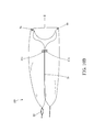
- FIGs. 2 , 3 and 4 in which since the section of the lateral heat sealing line 2a from the node 31a to the node 31b is not heat sealed, the lateral air cylinder 1 at the reserved non-heat sealing section 3 of the turning zone is expanded automatically to form a triangular cylinder opening 40 after the air cylinder sheet 200 is filled with air.
- This structure is simple, without the pointed protrusions at a corner air cylinder that usually happen in a conventional air bag, preventing the air cylinder sheet 200 from leaking due to a fissure caused from the abrasion of the pointed protrusion with an outer box upon transportation.
- the air cylinder 1 at the zone stay flatly close to a side of the outer box, thereby achieving a volume reduction, a cushioning effect of the section can be increased due to the triangular lateral air cylinder.
- the nodes 31a, 31b are marks being not necessarily heat sealing nodes.
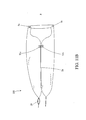
- FIGs. 3 and 5 in which two compressed corners 4 are positioned on the plurality of outer film 1a; the compressed corners 4 will be respectively formed on bent positions when the plurality of outer film 1a are filled with air to form air cylinders 1, and bent into a U-typed body. Consequently, the distance between the two sheets of outer film 1a at the bent position is smaller than the distance between the sheets of outer film 1a at other positions where the air cylinder 1 is not bent; the not-heat sealing section 3 of the turning zone combines substantially with the positions of the compressed corners 4 at the two sides to form a triangular body, and a bottom cushioning air cylinder 41 with a supporting surface 41a is included between the compressed corners 4 at the two sides.
- a bottom surface 41b is formed between the nodes 31a, 31b of the air cylinder sheet 200 after the air cylinder sheet 200 is filled with air, and the non-heat sealing section 3 of the turning zone is expanded to form the lateral polygonal opening 40 and so the supporting surface 41 a on the bottom of the opening 40.
- An object in the accepting space 10 will be against the bottom cushioning air cylinder 41 and the supporting surface 41a of the bottom cushioning air cylinder 41 may be against the table surface to perform a cushioning function after the object is placed in the bag body via the object storing opening 11.
- the plurality of outer films 1a is expanded by filling with air, and an opening 40 is so formed at the triangular zone.
- the air cylinder sheet 200 may be configured with a check valve, a plurality of air inlets 52 may be formed between two sheets of inner film 53, and each air inlet 52 corresponds to one air cylinder 1.
- the structure of the check valve 5 herein is only an example; a structure with a similar effect can only be configured depending on a practical structure requirement, and the present invention is not so limited.
- each air cylinder may be configured with its own check valve 5 such that only one air inlet 52 is formed between the two sheets of inner film 53 of the check valve 5.
- One part of the check valve 5 is positioned between the two sheets of outer film 1a and another part of the check valve 5 is exposed out in the air filling passageway 50.
- the air filling passageway 50 is preferably formed by adhering the two sheets of outer film 1a together by means of heat sealing, providing a route for air filling.
- the check valve 5 has a heat-resistant material 51, which is stuck to form the air inlet 52 by means of heat sealing, where the air inlet 52 is in air communication with the air filling passageway 50.
- the check valves 5 are formed by adhering the plurality of inner film 53 together by means of heat sealing, and a plurality of heat sealing switches 54 are included between the plurality of inner films 53 and the plurality of outer films 1a.
- the two sheets of outer film 1a are pulled apart outward after air is filled into the air filling passageway 50, driving each heat sealing switch 54 to pull the respective inner film 53 corresponding thereto apart outward, and further open the corresponding check valve 5, thereby allowing the air in the air filling passageway 50 to be filled between the plurality of outer films 1a via the check valves 5, and the space between the two sheets of outer sheet 1a to be expanded to form the air cylinders 1, Finally, the air cylinders 1 are bent to form a U-typed body.
- the two sheets of outer film 1a are pulled apart outward by air pressure in the air filling passageway 50 to drive the each heat sealing switch 54 to pull the respective inner film 53 corresponding thereto apart outward, and further to open each corresponding check valve 5, allowing the air in the air filling passageway 50 to be filled between the plurality of outer films 1a via the check valves 5, and the space between the two sheets of outer film 1a to be expanded to form the air cylinders 1, and the air cylinders 1 are finally bent to form a U-typed body.
- FIG. 7 the figure illustrates a second embodiment of the present invention.
- each two air cylinders 1 are partitioned by a heat sealing line 2, causing each two air cylinders 1 not to be in air communication with each other.
- An interval is included between a heat sealing line 2 and another heat sealing line 2.
- the position of the compressed corner 4 at this interval forms a first distance d
- the position of the bottom cushioning air cylinder 41 at this interval also forms a second distance D, where the first distance d is smaller than the second distance D.
- a first interval L1 is included between the two compressed corners 4 on a heat sealing line 2
- the non-heat sealing section 3 of the turning zone on a heat sealing line 2 is positioned between the first node 31a and the second node 31b and includes a second interval L2, where the first interval L1 is shorter than the second interval L2.
- FIGS. 8A , 8B , 9A , 9B , 10A , 10B , 11A and 11B in which the figures illustrate embodiments of contraction of lateral air cylinders in a turning zone; the lateral air cylinders 1 in the turning zone can be contracted depending on a practical use.
- the non-heat sealing section 3 of the turning zone that the side of the lateral air cylinder 1 is not intended to be sealed is adopted to contract the volume of the air cylinder 1, thereby preventing the air cylinder 1 from being stacked and so volume-expanded after being turned.
- the non-heat sealing section 3 of the turning zone is referred to a section of the lateral side of the air cylinder sheet 200 that is not heat-sealed after the air cylinder sheet 200 is bent in half along the turning middle line M, i.e.
- the lateral side of the air cylinder sheet 200 from the node 31a to the node 31b is not heat-sealed after the air cylinder sheet is bent in half.
- the two sheets of outer film 1a at the non-heat sealing section 3 of the turning zone can be adhered together by means of heat sealing to form various shapes of heat sealing blocks 32 such as rectangle, half ellipse, triangle or other irregularly shaped body.
- the heat sealing block 32 is narrower than the air cylinder, and two sections of the air cylinderlat the two sides of the heat sealing block 32 can then be in air communication with each other and so expanded after air filling.
- the heat sealing block 32 may abut upon the turning points 4a, 4b, and may also keep a distance from them, thereby allowing air flow.
- the heat sealing block 32 is narrower than the air cylinder and shorter than the non-heat sealing section 3 of the turning zone so as to reduce the area of the air cylinder 1 at the non-heat sealing section 3 of the turning zone.
- Methods for reducing the area of the lateral air cylinder 1 are the followings:
- a method for making a cushioning air bag with a predetermined opening at an air cylinder turning zone includes:
- a bottom surface 41b is formed between the turning points 4a, 4b of the air cylinder sheet 200, and the non-heat sealing section 3 of the turning zone is expanded to form a lateral polygonal opening 40, and a supporting surface 41a is formed on the bottom of the opening 40 after the air cylinder sheet 200 is filled with air.
- the two sheets of outer film 1a are expanded through air filling, and two compressed corners 4 are formed on the two sheets of outer film 1a; the non-heat sealing section 3 of the turning zone and the two compressed corners 4 form substantially the triangular opening 40, and the bottom cushioning air cylinder 41 is formed between the two compressed corners 4. Consequently, a packed object is buffered by the bottom cushioning air cylinder 41.
- a step of providing check valves 5 is further included after Step 101 of providing the two sheets of outer film 1a, where the structure of the check valve 5 is described above, the detail thereof is herein omitted.
- Air is filled in the air filling passageway 50 to pull the two sheets of outer film 1a apart outward, and the plurality of heat sealing switches 54 is then driven to further pull the two sheets of inner film 53 apart outward to open the check valves 5, allowing the air in the air filling passageway 50 to enter the plurality of outer films 1a via the check valves 5.
- Step 102 of providing a plurality of heat sealing lines 2 Furthermore, a space is provided between the any two adjacent longitudinal heat sealing lines 21 in Step 102 of providing a plurality of heat sealing lines 2. Specifically, the distance d between the compressed corner 4 is shorter than the length D of the bottom cushioning air cylinder 41, as FIG. 7 shows.
- an object is placed in an internal space of the air cylinder bag via an object storing opening, and the surface of the object is supported by a plurality of bottom cushioning air cylinders, allowing the object to be buffered, and the object is wrapped by the air cylinder bag, allowing the object to be protected at the same time.
- Configuring non-heat sealing sections on lateral sides of the turning zone in advance and contracting with a predetermined area on the air cylinder of the turning zone are used to adjust a lateral cushioning effect.
- a triangle of a lateral corner is automatically formed after the cushioning bag is filled with air. Therefore, the lateral portion is flat without any pointed angle, and the cushioning air bag containing the object can be attached to a table face stably without inclination.
- the triangular air cylinder formed after being filled with air and expanded belongs to an edge corner cushioning adjustment and is helpful for reducing an outer box space, thereby reducing the transportation cost.
Landscapes
- Engineering & Computer Science (AREA)
- Mechanical Engineering (AREA)
- Buffer Packaging (AREA)
- Bag Frames (AREA)
- Making Paper Articles (AREA)
Applications Claiming Priority (1)
| Application Number | Priority Date | Filing Date | Title |
|---|---|---|---|
| TW100150083A TWI426040B (zh) | 2011-12-31 | 2011-12-31 | A cushioning bag for preset opening of air column turning zone and a method for manufacturing the same |
Publications (3)
| Publication Number | Publication Date |
|---|---|
| EP2610050A2 true EP2610050A2 (de) | 2013-07-03 |
| EP2610050A3 EP2610050A3 (de) | 2014-01-22 |
| EP2610050B1 EP2610050B1 (de) | 2018-12-26 |
Family
ID=46548318
Family Applications (1)
| Application Number | Title | Priority Date | Filing Date |
|---|---|---|---|
| EP12177446.7A Active EP2610050B1 (de) | 2011-12-31 | 2012-07-23 | Kissen-Airbag mit vorbestimmter Öffnung in einem Luftzylinder-Faltbereich und Herstellung davon |
Country Status (3)
| Country | Link |
|---|---|
| US (1) | US9616634B2 (de) |
| EP (1) | EP2610050B1 (de) |
| TW (1) | TWI426040B (de) |
Cited By (9)
| Publication number | Priority date | Publication date | Assignee | Title |
|---|---|---|---|---|
| EP2778095A1 (de) * | 2013-03-12 | 2014-09-17 | Air- Bag Packing Co., Ltd. | Eckhülse mit hängemattenartiger Polsterstruktur |
| CN104787424A (zh) * | 2014-01-19 | 2015-07-22 | 上海艾尔贝包装科技发展有限公司 | 具有空气缓冲性能的包装盒及其应用 |
| WO2015106712A1 (zh) * | 2014-01-19 | 2015-07-23 | 上海艾尔贝包装科技发展有限公司 | 具有空气缓冲性能的包装盒及其应用 |
| EP2921425A1 (de) * | 2014-03-20 | 2015-09-23 | Air- Bag Packing Co., Ltd. | Polsterkissen mit lasthaltender Schicht zwischen nach innen gebogenen luftgefüllten Säulen |
| EP2921739A1 (de) * | 2014-03-20 | 2015-09-23 | Air- Bag Packing Co., Ltd. | Schwingungsdämpfende Lufthülle mit verbesserter Endverschlussstruktur |
| CN106313640A (zh) * | 2016-07-21 | 2017-01-11 | 戴国平 | 一种成品制袋机 |
| EP3248901A4 (de) * | 2015-01-23 | 2018-10-24 | Green Packaging Technology (Jiangsu) Co., Ltd. | Dämpfendes aufblasbares verpackungskissen |
| EP3575239A1 (de) * | 2018-05-31 | 2019-12-04 | Kunshan Airbag Packing Corp | Luftpolstertasche mit verbessertem schutz an den seiten und ecken |
| WO2020203070A1 (ja) * | 2019-04-01 | 2020-10-08 | 大和製罐株式会社 | シート材からなる自立容器 |
Families Citing this family (6)
| Publication number | Priority date | Publication date | Assignee | Title |
|---|---|---|---|---|
| US20140130461A1 (en) * | 2011-06-22 | 2014-05-15 | Pronova Ab | Device for producing shock-absorbing inflatable package and method for filling it |
| TW201529437A (zh) * | 2014-01-27 | 2015-08-01 | Air Bag Packing Co Ltd | 具有邊角改良結構之空氣防震套 |
| CN206569485U (zh) * | 2015-05-22 | 2017-10-20 | 聂会平 | 空气缓冲体及其充气系统和充气装置以及连续式空气缓冲体 |
| CN110577019A (zh) * | 2018-06-08 | 2019-12-17 | 新加坡商法科达拉有限公司台湾分公司 | 可伸缩调整的防撞充气护角 |
| CN110979997B (zh) * | 2019-12-16 | 2025-02-18 | 杭州丙甲科技有限公司 | 一种新型进气嘴流道及气柱袋 |
| CN113086421B (zh) * | 2020-01-08 | 2026-01-27 | 上海艾尔贝包装科技发展有限公司 | 包装装置、挡板及其包装方法 |
Family Cites Families (9)
| Publication number | Priority date | Publication date | Assignee | Title |
|---|---|---|---|---|
| US7000767B2 (en) * | 2004-05-26 | 2006-02-21 | Air-Paq, Inc. | Structure of air-packing device having improved shock absorbing capability |
| JP2006069621A (ja) * | 2004-09-02 | 2006-03-16 | Sanyo Engineering Kk | 包装用部材 |
| US7254932B2 (en) * | 2004-11-18 | 2007-08-14 | Air-Paq, Inc. | Multi-purpose air-packing method and system |
| KR200397141Y1 (ko) * | 2005-07-13 | 2005-09-28 | (주)에어텍네츄럴 | 공기 주입식 완충 포장재 구조 |
| TW200800744A (en) * | 2006-06-23 | 2008-01-01 | Yao-Sin Liao | Folding style air buffer device |
| TWM306989U (en) * | 2006-08-21 | 2007-03-01 | Yao-Sin Liao | Air sealing structure capable of accommodating different-sized package |
| TW200827253A (en) * | 2006-12-29 | 2008-07-01 | Chieh-Hua Liao | Block reinforced air enclosure and manufacture thereof |
| TWM327855U (en) * | 2007-08-23 | 2008-03-01 | Chieh-Hua Liao | Air-sealing body structure of multi-stage gripping type |
| CN101462624B (zh) * | 2007-12-19 | 2010-09-22 | 廖建华 | 真空吸束式气体包装袋及其包装方法 |
-
2011
- 2011-12-31 TW TW100150083A patent/TWI426040B/zh active
-
2012
- 2012-07-06 US US13/542,877 patent/US9616634B2/en not_active Expired - Fee Related
- 2012-07-23 EP EP12177446.7A patent/EP2610050B1/de active Active
Non-Patent Citations (1)
| Title |
|---|
| None |
Cited By (11)
| Publication number | Priority date | Publication date | Assignee | Title |
|---|---|---|---|---|
| EP2778095A1 (de) * | 2013-03-12 | 2014-09-17 | Air- Bag Packing Co., Ltd. | Eckhülse mit hängemattenartiger Polsterstruktur |
| CN104787424A (zh) * | 2014-01-19 | 2015-07-22 | 上海艾尔贝包装科技发展有限公司 | 具有空气缓冲性能的包装盒及其应用 |
| WO2015106712A1 (zh) * | 2014-01-19 | 2015-07-23 | 上海艾尔贝包装科技发展有限公司 | 具有空气缓冲性能的包装盒及其应用 |
| EP2921425A1 (de) * | 2014-03-20 | 2015-09-23 | Air- Bag Packing Co., Ltd. | Polsterkissen mit lasthaltender Schicht zwischen nach innen gebogenen luftgefüllten Säulen |
| EP2921739A1 (de) * | 2014-03-20 | 2015-09-23 | Air- Bag Packing Co., Ltd. | Schwingungsdämpfende Lufthülle mit verbesserter Endverschlussstruktur |
| EP3248901A4 (de) * | 2015-01-23 | 2018-10-24 | Green Packaging Technology (Jiangsu) Co., Ltd. | Dämpfendes aufblasbares verpackungskissen |
| CN106313640A (zh) * | 2016-07-21 | 2017-01-11 | 戴国平 | 一种成品制袋机 |
| EP3575239A1 (de) * | 2018-05-31 | 2019-12-04 | Kunshan Airbag Packing Corp | Luftpolstertasche mit verbessertem schutz an den seiten und ecken |
| US10974886B2 (en) * | 2018-05-31 | 2021-04-13 | Kunshan Airbag Packing Corp. | Air-sealed bag with enhanced side and corner protection |
| WO2020203070A1 (ja) * | 2019-04-01 | 2020-10-08 | 大和製罐株式会社 | シート材からなる自立容器 |
| JP2020169028A (ja) * | 2019-04-01 | 2020-10-15 | 大和製罐株式会社 | シート材からなる自立容器 |
Also Published As
| Publication number | Publication date |
|---|---|
| US20130171384A1 (en) | 2013-07-04 |
| TW201326002A (zh) | 2013-07-01 |
| TWI426040B (zh) | 2014-02-11 |
| EP2610050B1 (de) | 2018-12-26 |
| EP2610050A3 (de) | 2014-01-22 |
| US9616634B2 (en) | 2017-04-11 |
Similar Documents
| Publication | Publication Date | Title |
|---|---|---|
| EP2610050A2 (de) | Kissen-Airbag mit vorbestimmter Öffnung in einem Luftzylinder-Faltbereich und Herstellung davon | |
| CN105083757B (zh) | 多层式空气包装装置及其制造方法 | |
| US10793336B2 (en) | Crossed, staggered and stacked-type air packaging device, and manufacturing method therefor | |
| CN207791404U (zh) | 包装套筒以及包装件 | |
| TWI609824B (zh) | 空氣包裝裝置及其充氣閥和製造方法 | |
| CN104787424B (zh) | 具有空气缓冲性能的包装盒及其应用 | |
| JP2017507092A (ja) | 空気緩衝性能を有する梱包箱及びその適用 | |
| CN109969610B (zh) | 一种立体折叠式空气包装装置及其制造方法 | |
| TW201643084A (zh) | 流體容器及其截止閥和製造方法 | |
| US6032818A (en) | Liner | |
| CN105083755A (zh) | 一种方形空气包装装置及其制造方法 | |
| CN204150431U (zh) | 一种方形空气包装装置 | |
| CN2700260Y (zh) | 充气包装袋 | |
| CN205256991U (zh) | 可顺畅填充流体的流体容器 | |
| CN204846822U (zh) | 多层式空气包装装置 | |
| CA2567255C (en) | Folded alcohol beverage bag and method | |
| US20050031230A1 (en) | Self standing flexible container | |
| JP4786640B2 (ja) | 筒状袋本体と封着底を備えた筒状袋 | |
| JP2015524776A (ja) | 膨張性パッケージおよびその製造方法 | |
| JP7576925B2 (ja) | 口部材を備えた流体充填式袋状容器 | |
| TWM531452U (zh) | 空氣包裝裝置及其充氣閥 | |
| JP5542979B1 (ja) | 気室の曲がりゾーンに開口を予め設けた緩衝空気袋及びその製造方法 | |
| JP2003155065A (ja) | 緩衝用包装材およびその製造方法 | |
| TWM531453U (zh) | 流體容器及其截止閥 | |
| CN118665841A (zh) | 充气包装袋 |
Legal Events
| Date | Code | Title | Description |
|---|---|---|---|
| PUAI | Public reference made under article 153(3) epc to a published international application that has entered the european phase |
Free format text: ORIGINAL CODE: 0009012 |
|
| AK | Designated contracting states |
Kind code of ref document: A2 Designated state(s): AL AT BE BG CH CY CZ DE DK EE ES FI FR GB GR HR HU IE IS IT LI LT LU LV MC MK MT NL NO PL PT RO RS SE SI SK SM TR |
|
| AX | Request for extension of the european patent |
Extension state: BA ME |
|
| PUAL | Search report despatched |
Free format text: ORIGINAL CODE: 0009013 |
|
| AK | Designated contracting states |
Kind code of ref document: A3 Designated state(s): AL AT BE BG CH CY CZ DE DK EE ES FI FR GB GR HR HU IE IS IT LI LT LU LV MC MK MT NL NO PL PT RO RS SE SI SK SM TR |
|
| AX | Request for extension of the european patent |
Extension state: BA ME |
|
| RIC1 | Information provided on ipc code assigned before grant |
Ipc: B65D 81/05 20060101ALI20131218BHEP Ipc: B31D 5/00 20060101AFI20131218BHEP |
|
| 17P | Request for examination filed |
Effective date: 20140623 |
|
| RBV | Designated contracting states (corrected) |
Designated state(s): AL AT BE BG CH CY CZ DE DK EE ES FI FR GB GR HR HU IE IS IT LI LT LU LV MC MK MT NL NO PL PT RO RS SE SI SK SM TR |
|
| RIN1 | Information on inventor provided before grant (corrected) |
Inventor name: LIAO, CHIEH-HUA |
|
| 17Q | First examination report despatched |
Effective date: 20160704 |
|
| STAA | Information on the status of an ep patent application or granted ep patent |
Free format text: STATUS: EXAMINATION IS IN PROGRESS |
|
| RIC1 | Information provided on ipc code assigned before grant |
Ipc: B65D 81/03 20060101ALI20180607BHEP Ipc: B65D 30/24 20060101ALN20180607BHEP Ipc: B65D 81/05 20060101ALI20180607BHEP Ipc: B31D 5/00 20060101AFI20180607BHEP |
|
| GRAP | Despatch of communication of intention to grant a patent |
Free format text: ORIGINAL CODE: EPIDOSNIGR1 |
|
| STAA | Information on the status of an ep patent application or granted ep patent |
Free format text: STATUS: GRANT OF PATENT IS INTENDED |
|
| RIC1 | Information provided on ipc code assigned before grant |
Ipc: B31D 5/00 20060101AFI20180629BHEP Ipc: B65D 81/03 20060101ALI20180629BHEP Ipc: B65D 81/05 20060101ALI20180629BHEP Ipc: B65D 30/24 20060101ALN20180629BHEP |
|
| INTG | Intention to grant announced |
Effective date: 20180720 |
|
| GRAS | Grant fee paid |
Free format text: ORIGINAL CODE: EPIDOSNIGR3 |
|
| GRAA | (expected) grant |
Free format text: ORIGINAL CODE: 0009210 |
|
| STAA | Information on the status of an ep patent application or granted ep patent |
Free format text: STATUS: THE PATENT HAS BEEN GRANTED |
|
| AK | Designated contracting states |
Kind code of ref document: B1 Designated state(s): AL AT BE BG CH CY CZ DE DK EE ES FI FR GB GR HR HU IE IS IT LI LT LU LV MC MK MT NL NO PL PT RO RS SE SI SK SM TR |
|
| REG | Reference to a national code |
Ref country code: GB Ref legal event code: FG4D |
|
| REG | Reference to a national code |
Ref country code: CH Ref legal event code: EP |
|
| REG | Reference to a national code |
Ref country code: AT Ref legal event code: REF Ref document number: 1080829 Country of ref document: AT Kind code of ref document: T Effective date: 20190115 |
|
| REG | Reference to a national code |
Ref country code: DE Ref legal event code: R096 Ref document number: 602012055053 Country of ref document: DE |
|
| REG | Reference to a national code |
Ref country code: IE Ref legal event code: FG4D |
|
| PG25 | Lapsed in a contracting state [announced via postgrant information from national office to epo] |
Ref country code: BG Free format text: LAPSE BECAUSE OF FAILURE TO SUBMIT A TRANSLATION OF THE DESCRIPTION OR TO PAY THE FEE WITHIN THE PRESCRIBED TIME-LIMIT Effective date: 20190326 Ref country code: HR Free format text: LAPSE BECAUSE OF FAILURE TO SUBMIT A TRANSLATION OF THE DESCRIPTION OR TO PAY THE FEE WITHIN THE PRESCRIBED TIME-LIMIT Effective date: 20181226 Ref country code: LT Free format text: LAPSE BECAUSE OF FAILURE TO SUBMIT A TRANSLATION OF THE DESCRIPTION OR TO PAY THE FEE WITHIN THE PRESCRIBED TIME-LIMIT Effective date: 20181226 Ref country code: NO Free format text: LAPSE BECAUSE OF FAILURE TO SUBMIT A TRANSLATION OF THE DESCRIPTION OR TO PAY THE FEE WITHIN THE PRESCRIBED TIME-LIMIT Effective date: 20190326 Ref country code: LV Free format text: LAPSE BECAUSE OF FAILURE TO SUBMIT A TRANSLATION OF THE DESCRIPTION OR TO PAY THE FEE WITHIN THE PRESCRIBED TIME-LIMIT Effective date: 20181226 Ref country code: FI Free format text: LAPSE BECAUSE OF FAILURE TO SUBMIT A TRANSLATION OF THE DESCRIPTION OR TO PAY THE FEE WITHIN THE PRESCRIBED TIME-LIMIT Effective date: 20181226 |
|
| REG | Reference to a national code |
Ref country code: NL Ref legal event code: MP Effective date: 20181226 |
|
| REG | Reference to a national code |
Ref country code: LT Ref legal event code: MG4D |
|
| PG25 | Lapsed in a contracting state [announced via postgrant information from national office to epo] |
Ref country code: SE Free format text: LAPSE BECAUSE OF FAILURE TO SUBMIT A TRANSLATION OF THE DESCRIPTION OR TO PAY THE FEE WITHIN THE PRESCRIBED TIME-LIMIT Effective date: 20181226 Ref country code: AL Free format text: LAPSE BECAUSE OF FAILURE TO SUBMIT A TRANSLATION OF THE DESCRIPTION OR TO PAY THE FEE WITHIN THE PRESCRIBED TIME-LIMIT Effective date: 20181226 Ref country code: RS Free format text: LAPSE BECAUSE OF FAILURE TO SUBMIT A TRANSLATION OF THE DESCRIPTION OR TO PAY THE FEE WITHIN THE PRESCRIBED TIME-LIMIT Effective date: 20181226 Ref country code: GR Free format text: LAPSE BECAUSE OF FAILURE TO SUBMIT A TRANSLATION OF THE DESCRIPTION OR TO PAY THE FEE WITHIN THE PRESCRIBED TIME-LIMIT Effective date: 20190327 |
|
| REG | Reference to a national code |
Ref country code: AT Ref legal event code: MK05 Ref document number: 1080829 Country of ref document: AT Kind code of ref document: T Effective date: 20181226 |
|
| PG25 | Lapsed in a contracting state [announced via postgrant information from national office to epo] |
Ref country code: NL Free format text: LAPSE BECAUSE OF FAILURE TO SUBMIT A TRANSLATION OF THE DESCRIPTION OR TO PAY THE FEE WITHIN THE PRESCRIBED TIME-LIMIT Effective date: 20181226 |
|
| PG25 | Lapsed in a contracting state [announced via postgrant information from national office to epo] |
Ref country code: PT Free format text: LAPSE BECAUSE OF FAILURE TO SUBMIT A TRANSLATION OF THE DESCRIPTION OR TO PAY THE FEE WITHIN THE PRESCRIBED TIME-LIMIT Effective date: 20190426 Ref country code: IT Free format text: LAPSE BECAUSE OF FAILURE TO SUBMIT A TRANSLATION OF THE DESCRIPTION OR TO PAY THE FEE WITHIN THE PRESCRIBED TIME-LIMIT Effective date: 20181226 Ref country code: ES Free format text: LAPSE BECAUSE OF FAILURE TO SUBMIT A TRANSLATION OF THE DESCRIPTION OR TO PAY THE FEE WITHIN THE PRESCRIBED TIME-LIMIT Effective date: 20181226 Ref country code: PL Free format text: LAPSE BECAUSE OF FAILURE TO SUBMIT A TRANSLATION OF THE DESCRIPTION OR TO PAY THE FEE WITHIN THE PRESCRIBED TIME-LIMIT Effective date: 20181226 |
|
| PG25 | Lapsed in a contracting state [announced via postgrant information from national office to epo] |
Ref country code: IS Free format text: LAPSE BECAUSE OF FAILURE TO SUBMIT A TRANSLATION OF THE DESCRIPTION OR TO PAY THE FEE WITHIN THE PRESCRIBED TIME-LIMIT Effective date: 20190426 Ref country code: SK Free format text: LAPSE BECAUSE OF FAILURE TO SUBMIT A TRANSLATION OF THE DESCRIPTION OR TO PAY THE FEE WITHIN THE PRESCRIBED TIME-LIMIT Effective date: 20181226 Ref country code: RO Free format text: LAPSE BECAUSE OF FAILURE TO SUBMIT A TRANSLATION OF THE DESCRIPTION OR TO PAY THE FEE WITHIN THE PRESCRIBED TIME-LIMIT Effective date: 20181226 Ref country code: EE Free format text: LAPSE BECAUSE OF FAILURE TO SUBMIT A TRANSLATION OF THE DESCRIPTION OR TO PAY THE FEE WITHIN THE PRESCRIBED TIME-LIMIT Effective date: 20181226 Ref country code: SM Free format text: LAPSE BECAUSE OF FAILURE TO SUBMIT A TRANSLATION OF THE DESCRIPTION OR TO PAY THE FEE WITHIN THE PRESCRIBED TIME-LIMIT Effective date: 20181226 |
|
| REG | Reference to a national code |
Ref country code: DE Ref legal event code: R097 Ref document number: 602012055053 Country of ref document: DE |
|
| PG25 | Lapsed in a contracting state [announced via postgrant information from national office to epo] |
Ref country code: AT Free format text: LAPSE BECAUSE OF FAILURE TO SUBMIT A TRANSLATION OF THE DESCRIPTION OR TO PAY THE FEE WITHIN THE PRESCRIBED TIME-LIMIT Effective date: 20181226 Ref country code: DK Free format text: LAPSE BECAUSE OF FAILURE TO SUBMIT A TRANSLATION OF THE DESCRIPTION OR TO PAY THE FEE WITHIN THE PRESCRIBED TIME-LIMIT Effective date: 20181226 |
|
| PGFP | Annual fee paid to national office [announced via postgrant information from national office to epo] |
Ref country code: CZ Payment date: 20190719 Year of fee payment: 8 |
|
| PLBE | No opposition filed within time limit |
Free format text: ORIGINAL CODE: 0009261 |
|
| STAA | Information on the status of an ep patent application or granted ep patent |
Free format text: STATUS: NO OPPOSITION FILED WITHIN TIME LIMIT |
|
| 26N | No opposition filed |
Effective date: 20190927 |
|
| PGFP | Annual fee paid to national office [announced via postgrant information from national office to epo] |
Ref country code: GB Payment date: 20190725 Year of fee payment: 8 |
|
| PG25 | Lapsed in a contracting state [announced via postgrant information from national office to epo] |
Ref country code: SI Free format text: LAPSE BECAUSE OF FAILURE TO SUBMIT A TRANSLATION OF THE DESCRIPTION OR TO PAY THE FEE WITHIN THE PRESCRIBED TIME-LIMIT Effective date: 20181226 Ref country code: MC Free format text: LAPSE BECAUSE OF FAILURE TO SUBMIT A TRANSLATION OF THE DESCRIPTION OR TO PAY THE FEE WITHIN THE PRESCRIBED TIME-LIMIT Effective date: 20181226 |
|
| REG | Reference to a national code |
Ref country code: CH Ref legal event code: PL |
|
| PG25 | Lapsed in a contracting state [announced via postgrant information from national office to epo] |
Ref country code: TR Free format text: LAPSE BECAUSE OF FAILURE TO SUBMIT A TRANSLATION OF THE DESCRIPTION OR TO PAY THE FEE WITHIN THE PRESCRIBED TIME-LIMIT Effective date: 20181226 |
|
| REG | Reference to a national code |
Ref country code: BE Ref legal event code: MM Effective date: 20190731 |
|
| PG25 | Lapsed in a contracting state [announced via postgrant information from national office to epo] |
Ref country code: LU Free format text: LAPSE BECAUSE OF NON-PAYMENT OF DUE FEES Effective date: 20190723 Ref country code: CH Free format text: LAPSE BECAUSE OF NON-PAYMENT OF DUE FEES Effective date: 20190731 Ref country code: BE Free format text: LAPSE BECAUSE OF NON-PAYMENT OF DUE FEES Effective date: 20190731 Ref country code: LI Free format text: LAPSE BECAUSE OF NON-PAYMENT OF DUE FEES Effective date: 20190731 |
|
| PG25 | Lapsed in a contracting state [announced via postgrant information from national office to epo] |
Ref country code: FR Free format text: LAPSE BECAUSE OF NON-PAYMENT OF DUE FEES Effective date: 20190731 |
|
| PG25 | Lapsed in a contracting state [announced via postgrant information from national office to epo] |
Ref country code: IE Free format text: LAPSE BECAUSE OF NON-PAYMENT OF DUE FEES Effective date: 20190723 |
|
| GBPC | Gb: european patent ceased through non-payment of renewal fee |
Effective date: 20200723 |
|
| PG25 | Lapsed in a contracting state [announced via postgrant information from national office to epo] |
Ref country code: GB Free format text: LAPSE BECAUSE OF NON-PAYMENT OF DUE FEES Effective date: 20200723 Ref country code: CZ Free format text: LAPSE BECAUSE OF NON-PAYMENT OF DUE FEES Effective date: 20200723 |
|
| PG25 | Lapsed in a contracting state [announced via postgrant information from national office to epo] |
Ref country code: CY Free format text: LAPSE BECAUSE OF FAILURE TO SUBMIT A TRANSLATION OF THE DESCRIPTION OR TO PAY THE FEE WITHIN THE PRESCRIBED TIME-LIMIT Effective date: 20181226 |
|
| PG25 | Lapsed in a contracting state [announced via postgrant information from national office to epo] |
Ref country code: MT Free format text: LAPSE BECAUSE OF FAILURE TO SUBMIT A TRANSLATION OF THE DESCRIPTION OR TO PAY THE FEE WITHIN THE PRESCRIBED TIME-LIMIT Effective date: 20181226 Ref country code: HU Free format text: LAPSE BECAUSE OF FAILURE TO SUBMIT A TRANSLATION OF THE DESCRIPTION OR TO PAY THE FEE WITHIN THE PRESCRIBED TIME-LIMIT; INVALID AB INITIO Effective date: 20120723 |
|
| PG25 | Lapsed in a contracting state [announced via postgrant information from national office to epo] |
Ref country code: MK Free format text: LAPSE BECAUSE OF FAILURE TO SUBMIT A TRANSLATION OF THE DESCRIPTION OR TO PAY THE FEE WITHIN THE PRESCRIBED TIME-LIMIT Effective date: 20181226 |
|
| PGFP | Annual fee paid to national office [announced via postgrant information from national office to epo] |
Ref country code: DE Payment date: 20250625 Year of fee payment: 14 |