EP2609025B1 - Collating machine - Google Patents
Collating machine Download PDFInfo
- Publication number
- EP2609025B1 EP2609025B1 EP11764082.1A EP11764082A EP2609025B1 EP 2609025 B1 EP2609025 B1 EP 2609025B1 EP 11764082 A EP11764082 A EP 11764082A EP 2609025 B1 EP2609025 B1 EP 2609025B1
- Authority
- EP
- European Patent Office
- Prior art keywords
- stack
- sheet
- magazine
- machine according
- collating machine
- Prior art date
- Legal status (The legal status is an assumption and is not a legal conclusion. Google has not performed a legal analysis and makes no representation as to the accuracy of the status listed.)
- Not-in-force
Links
Images


Classifications
-
- B—PERFORMING OPERATIONS; TRANSPORTING
- B65—CONVEYING; PACKING; STORING; HANDLING THIN OR FILAMENTARY MATERIAL
- B65H—HANDLING THIN OR FILAMENTARY MATERIAL, e.g. SHEETS, WEBS, CABLES
- B65H39/00—Associating, collating, or gathering articles or webs
- B65H39/02—Associating,collating or gathering articles from several sources
- B65H39/04—Associating,collating or gathering articles from several sources from piles
- B65H39/043—Associating,collating or gathering articles from several sources from piles the piles being disposed in juxtaposed carriers
-
- B—PERFORMING OPERATIONS; TRANSPORTING
- B42—BOOKBINDING; ALBUMS; FILES; SPECIAL PRINTED MATTER
- B42C—BOOKBINDING
- B42C1/00—Collating or gathering sheets combined with processes for permanently attaching together sheets or signatures or for interposing inserts
- B42C1/12—Machines for both collating or gathering and permanently attaching together the sheets or signatures
-
- B—PERFORMING OPERATIONS; TRANSPORTING
- B65—CONVEYING; PACKING; STORING; HANDLING THIN OR FILAMENTARY MATERIAL
- B65H—HANDLING THIN OR FILAMENTARY MATERIAL, e.g. SHEETS, WEBS, CABLES
- B65H1/00—Supports or magazines for piles from which articles are to be separated
- B65H1/04—Supports or magazines for piles from which articles are to be separated adapted to support articles substantially horizontally, e.g. for separation from top of pile
- B65H1/06—Supports or magazines for piles from which articles are to be separated adapted to support articles substantially horizontally, e.g. for separation from top of pile for separation from bottom of pile
-
- B—PERFORMING OPERATIONS; TRANSPORTING
- B65—CONVEYING; PACKING; STORING; HANDLING THIN OR FILAMENTARY MATERIAL
- B65H—HANDLING THIN OR FILAMENTARY MATERIAL, e.g. SHEETS, WEBS, CABLES
- B65H1/00—Supports or magazines for piles from which articles are to be separated
- B65H1/08—Supports or magazines for piles from which articles are to be separated with means for advancing the articles to present the articles to the separating device
- B65H1/14—Supports or magazines for piles from which articles are to be separated with means for advancing the articles to present the articles to the separating device comprising positively-acting mechanical devices
-
- B—PERFORMING OPERATIONS; TRANSPORTING
- B65—CONVEYING; PACKING; STORING; HANDLING THIN OR FILAMENTARY MATERIAL
- B65H—HANDLING THIN OR FILAMENTARY MATERIAL, e.g. SHEETS, WEBS, CABLES
- B65H3/00—Separating articles from piles
- B65H3/02—Separating articles from piles using friction forces between articles and separator
- B65H3/04—Endless-belt separators
- B65H3/042—Endless-belt separators separating from the bottom of the pile
-
- B—PERFORMING OPERATIONS; TRANSPORTING
- B65—CONVEYING; PACKING; STORING; HANDLING THIN OR FILAMENTARY MATERIAL
- B65H—HANDLING THIN OR FILAMENTARY MATERIAL, e.g. SHEETS, WEBS, CABLES
- B65H3/00—Separating articles from piles
- B65H3/02—Separating articles from piles using friction forces between articles and separator
- B65H3/04—Endless-belt separators
- B65H3/047—Endless-belt separators separating from the top of a pile
-
- B—PERFORMING OPERATIONS; TRANSPORTING
- B65—CONVEYING; PACKING; STORING; HANDLING THIN OR FILAMENTARY MATERIAL
- B65H—HANDLING THIN OR FILAMENTARY MATERIAL, e.g. SHEETS, WEBS, CABLES
- B65H3/00—Separating articles from piles
- B65H3/08—Separating articles from piles using pneumatic force
- B65H3/0808—Suction grippers
- B65H3/0816—Suction grippers separating from the top of pile
- B65H3/0833—Suction grippers separating from the top of pile and acting on the front part of the articles relatively to the final separating direction
-
- B—PERFORMING OPERATIONS; TRANSPORTING
- B65—CONVEYING; PACKING; STORING; HANDLING THIN OR FILAMENTARY MATERIAL
- B65H—HANDLING THIN OR FILAMENTARY MATERIAL, e.g. SHEETS, WEBS, CABLES
- B65H3/00—Separating articles from piles
- B65H3/08—Separating articles from piles using pneumatic force
- B65H3/0808—Suction grippers
- B65H3/085—Suction grippers separating from the bottom of pile
-
- B—PERFORMING OPERATIONS; TRANSPORTING
- B65—CONVEYING; PACKING; STORING; HANDLING THIN OR FILAMENTARY MATERIAL
- B65H—HANDLING THIN OR FILAMENTARY MATERIAL, e.g. SHEETS, WEBS, CABLES
- B65H3/00—Separating articles from piles
- B65H3/46—Supplementary devices or measures to assist separation or prevent double feed
- B65H3/50—Elements, e.g. fingers, plates, rollers, inserted or traversed between articles to be separated and remainder of the pile
-
- B—PERFORMING OPERATIONS; TRANSPORTING
- B65—CONVEYING; PACKING; STORING; HANDLING THIN OR FILAMENTARY MATERIAL
- B65H—HANDLING THIN OR FILAMENTARY MATERIAL, e.g. SHEETS, WEBS, CABLES
- B65H39/00—Associating, collating, or gathering articles or webs
- B65H39/02—Associating,collating or gathering articles from several sources
- B65H39/04—Associating,collating or gathering articles from several sources from piles
- B65H39/042—Associating,collating or gathering articles from several sources from piles the piles being disposed in superposed carriers
-
- B—PERFORMING OPERATIONS; TRANSPORTING
- B65—CONVEYING; PACKING; STORING; HANDLING THIN OR FILAMENTARY MATERIAL
- B65H—HANDLING THIN OR FILAMENTARY MATERIAL, e.g. SHEETS, WEBS, CABLES
- B65H5/00—Feeding articles separated from piles; Feeding articles to machines
- B65H5/02—Feeding articles separated from piles; Feeding articles to machines by belts or chains, e.g. between belts or chains
- B65H5/021—Feeding articles separated from piles; Feeding articles to machines by belts or chains, e.g. between belts or chains by belts
- B65H5/023—Feeding articles separated from piles; Feeding articles to machines by belts or chains, e.g. between belts or chains by belts between a pair of belts forming a transport nip
-
- B—PERFORMING OPERATIONS; TRANSPORTING
- B65—CONVEYING; PACKING; STORING; HANDLING THIN OR FILAMENTARY MATERIAL
- B65H—HANDLING THIN OR FILAMENTARY MATERIAL, e.g. SHEETS, WEBS, CABLES
- B65H2301/00—Handling processes for sheets or webs
- B65H2301/40—Type of handling process
- B65H2301/44—Moving, forwarding, guiding material
- B65H2301/443—Moving, forwarding, guiding material by acting on surface of handled material
- B65H2301/4431—Moving, forwarding, guiding material by acting on surface of handled material by means with operating surfaces contacting opposite faces of material
- B65H2301/44316—Moving, forwarding, guiding material by acting on surface of handled material by means with operating surfaces contacting opposite faces of material between belts
-
- B—PERFORMING OPERATIONS; TRANSPORTING
- B65—CONVEYING; PACKING; STORING; HANDLING THIN OR FILAMENTARY MATERIAL
- B65H—HANDLING THIN OR FILAMENTARY MATERIAL, e.g. SHEETS, WEBS, CABLES
- B65H2301/00—Handling processes for sheets or webs
- B65H2301/40—Type of handling process
- B65H2301/44—Moving, forwarding, guiding material
- B65H2301/447—Moving, forwarding, guiding material transferring material between transport devices
- B65H2301/4474—Pair of cooperating moving elements as rollers, belts forming nip into which material is transported
-
- B—PERFORMING OPERATIONS; TRANSPORTING
- B65—CONVEYING; PACKING; STORING; HANDLING THIN OR FILAMENTARY MATERIAL
- B65H—HANDLING THIN OR FILAMENTARY MATERIAL, e.g. SHEETS, WEBS, CABLES
- B65H2405/00—Parts for holding the handled material
- B65H2405/30—Other features of supports for sheets
- B65H2405/33—Compartmented support
- B65H2405/332—Superposed compartments
-
- B—PERFORMING OPERATIONS; TRANSPORTING
- B65—CONVEYING; PACKING; STORING; HANDLING THIN OR FILAMENTARY MATERIAL
- B65H—HANDLING THIN OR FILAMENTARY MATERIAL, e.g. SHEETS, WEBS, CABLES
- B65H2601/00—Problem to be solved or advantage achieved
- B65H2601/30—Facilitating or easing
- B65H2601/32—Facilitating or easing entities relating to handling machine
- B65H2601/322—Replenishing
-
- B—PERFORMING OPERATIONS; TRANSPORTING
- B65—CONVEYING; PACKING; STORING; HANDLING THIN OR FILAMENTARY MATERIAL
- B65H—HANDLING THIN OR FILAMENTARY MATERIAL, e.g. SHEETS, WEBS, CABLES
- B65H2601/00—Problem to be solved or advantage achieved
- B65H2601/50—Diminishing, minimizing or reducing
- B65H2601/52—Diminishing, minimizing or reducing entities relating to handling machine
- B65H2601/523—Required space
Definitions
- the invention relates to a gathering machine with at least two adjacent stations, each storing a stack of identical printing sheets, and a transport that connects all stations, from each station a sheet is fed to the already assembled sub-block, and the finished together worn block supplies.
- the gathering operation serves to gather folded sheets or single sheets, previously printed in printing presses and possibly folded in folding machines, into a block in the correct sequential order.
- the sheets or fold sheets that belong to a block are stacked on top of each other.
- the various sheets are located in successive arranged in a collator stations with magazines.
- the blocks are successively transported in close succession through the stations of the gathering machine, at each station the block is supplemented by another arc until it is completed. As it passes through the stations, the block grows from the initial thickness to the final thickness.
- the initial thickness is usually zero. But it can also be introduced a sub-block in the gathering machine, where then the initial thickness has the appropriate value.
- the separation of a sheet from a stack with the same sheet can, for example, as in DE1919418 is proposed to take place upwards by suction via suction on an edge of the sheet, wherein the stack is flat.
- the isolated sheet is then brought laterally by the suckers to a transport shaft and placed on the already assembled sub-block.
- the blocks are transported linearly past the magazines.
- the top edge of the stack is always kept constant to allow separation by the suckers.
- the separation to the top is good for single sheets that are flat, but not for folded sheets, which offer no flat surface because of the folding edge structure for the singling suction.
- the lateral transport of the isolated sheets to the transport channel is transverse to the transport direction.
- the time required for the movement of the mechanism and the abrupt acceleration of the deposited sheet on the linear transport speed limit the performance of such machines very much. They also have a lot of space. This principle is mainly used as a form-setter.
- the magazines can be arranged in a certain number on top of each other, such as in EP 1584589 to see.
- the separation from the plan lying stack is done by suction upwards.
- the isolated sheets are fed to the vertical transport, where they are deflected without speed change from the horizontal to the vertical direction.
- the weight of the stack creates frictional forces that act on the sheet overlying the sheet being withdrawn.
- the weight in the magazine must be kept very small, which of course reduces the magazine capacity. In these magazines but can be done advantageously in the barrel.
- the sheet is immediately deducted from the magazine in the transport direction and avoided the 90 ° deflection of the movement and thus the abrupt acceleration of the arc in the other solutions in the transport direction.
- the lowermost sheet is first separated at one corner by suction, conveyed by a suction plate from the magazine and conveyed by upper and lower belts obliquely downwards in the transport direction in the transport channel, where it is then linearly transported together with the already collected sub-block by transporters.
- the transport takes place with all these solutions in the transport shaft via transporters, which are fixed at intervals on a chain and are moved by this continuously in the transport direction.
- the collapsed sub-block are pushed at the trailing edge. If there is a single sheet at the top, it tends to fly up. The speed must then be significantly reduced.
- the gathering takes place either before the adhesive binding or before the saddle stitching.
- Adhesive bonding For adhesive bonding, the blocks are transported flat through the machine and erected after leaving the gathering machine in front of the perfect binder. Adhesive bonding also produces thicker blocks that require a high number of gathering stations, resulting in a large machine length.
- the transport can then be simply lying flat instead of a semitransport.
- the stations are arranged one behind the other horizontally or vertically one above the other with the disadvantages already mentioned regarding either space or inaccessibility of the magazines.
- a major problem with gathering machines is the reliability of the separation.
- the object of the present invention is to develop a gathering machine of the generic type so that is suitable for use in adhesive binding and saddle stitching, which can handle both folded layers and single sheets with optimum reliability, which requires little space and good accessibility of the Magazine for refilling has.
- Essential to the invention is that the machine consists of several successively arranged stations that are connected to each other via a linear transport consists.
- Each station contains an upper magazine with separation of the lower sheet down and a lower magazine with separation of the uppermost sheet to the top.
- the magazines of a station are arranged one above the other, which halves the required space compared to the prior art for a given number of magazines.
- the upper and lower magazines feed at the same place independently in the longitudinal transport over points, so that they can be used either simultaneously or alternatively.
- a singling up and down has different advantages and disadvantages and is different well suited for folded layers or single sheets.
- the optional use of the upper or lower magazines makes it possible to achieve optimum functional reliability for the corresponding product, which is of crucial importance for the effective performance of the machine.
- the upper magazines work without stopping and are easily accessible for refilling.
- the lower magazines have a very large storage capacity, so that replenishment associated with stopping the machine is very rare.
- the longitudinal transport takes place backwards.
- the sub-blocks are clamped between two upper and two lower main transport belt, which run continuously and which are interrupted at the feed points of the upper and lower magazines for a short distance.
- the distance between the upper and lower belts to each other is adjustable to the partial block thickness. A slight adjustment to the block thickness is made by compression.
- the main transport belts always move the collected sub-block a certain distance away from the sides, which is automatically kept constant during format adjustment.
- separation springs prevent the next sheet from going along with the current arc, creating a double trigger.
- a wedge penetrates, which presses down the back of the sheet on the entire format length, so that a line is formed over the entire width of the sheet.
- the wedge also supports the back area of the stack. This is important for the upper magazines. The friction of the isolated sheet when pulling out of the magazine generates friction on the overlying sheet and tries to prefer this and spatialbulen in the space between the support table and backstop and so jeopardize the next separation process.
- the wedge is retracted throughout the extraction phase and the sucker swung.
- the wedge moves off again. After swiveling the vacuum cleaner to separate the corner of the sheet, the wedge retracts immediately.
- the wedge In the wedge is the front deflection of a conveyor belt for extracting the sheets, both in the lower and in the upper magazines.
- the deflection diameter is small, so that the pulley can penetrate very far within the gap between the individual sheet and stack.
- the deflection pulley On the last piece of stroke when retracting the wedge, the deflection pulley is pressed together with the Auszugstrartsportriemen against a counter-belt and clamped the back portion of the bow.
- the pullout conveyor belts are located on both sides close to the main transport belt. At the moment of contact, the pullout conveyor belts begin to move at synchronous speed to the main conveyor belts and bring the block into the main conveyor belts through the space provided for it. The time is adjusted so that the arc is congruent to the already collected sub-block supplied. That can happen simultaneously from below and above.
- the Walk roller In the upper magazine is a walk roller under the stack. She reaches through the arch support table. The stack weighs on her with his weight. In the lower magazine, the Walk roller with its weight and any additional spring force on the stack in the smallest format area.
- the Walkwalze is freely running on an axle. This axis makes a circular movement over eccentric pins. It touches the stack surface on a part of the movement. In the other part of the movement, there is no contact with the stack.
- the rotational movement of the eccentrically mounted axis is such that the Walk roller rolls in contact with the stack at this from the head stop away. She does one revolution per bar. This creates a walkteffect that shifts the individual leaves slightly up to a certain depth of action.
- the leaves are fanned slightly and Schneidgrat separated, so that the separation can be done without interference.
- the displacement of the leaves away from the head takes place only until the sheets are in front of a stop located on the opposite side. This creates a slope in the last area of the stack, which supports the work of the separation spring.
- the bows that restrained are always minimally available and offer the separation spring an attack edge.
- the loading height of the upper magazines must be kept low and should fluctuate as little as possible.
- an automatic Nachlade Anlagenkeit is provided. Low height stacks are placed on a conveyor belt outside the frame of the machine.
- the conveyor belt is designed to be displaceable as a whole conveyor belt unit and arranged in terms of height so that it is in the inserted state at a certain distance above the support table of the upper magazine. If the supply in the upper magazine is so far used that the upper edge of the rest of the stack is slightly lower than the conveyor belt, this is inserted with a stack thereon, so that the supplied stack is at the desired position in the magazine. For this purpose, the movement of the band is blocked relative to its movable frame.
- the conveyor belt unit is withdrawn, thereby blocking the belt from the frame of the machine, so that it moves relative to the frame of the conveyor belt unit.
- the stack is stored true to the position on the remaining stack. Then a new stack can be placed on the tape and is there in readiness when the upper magazine must be reloaded.
- the lower magazines are not non-stop magazines. They have a large storage capacity for this.
- the lift table can be controlled separately on the right and left.
- the separate control can help to compensate for different pressure build-up over the arc surface so that the suckers have optimal suction conditions left and right.
- a double station with two upper and two lower magazines consists of the lower side walls 1, which are interconnected via support 2, the upper side plates 4, compared to the lower side walls 1 in height to block thickness in a known manner, not shown on format thickness are adjustable, and the two upper and two lower separating units. 5
- the separation units 5 contain main transport belt 6, separating wedge 12, transport belt 15 for the extension, transport belt 22 as a counter belt, telescopic suction device 30 with control.
- the main transport belt 6 with the guide wheels 7 and 8 transport the sub-block from station to station, where then each a sheet is fed from below and / or above.
- the deflection wheel 8 is driven continuously, wherein the power transmission takes place by a splined shaft 9.
- the separating wedge 12 is pivoted by the control cam 13 in the gap between the individual sheet and stack, on the one handfinekippen the one tipped at the corners by the telescopic suction 30 arc across the width and on the other hand when pulling the sheet against the frictional forces acting on the stack To avoid pulling the next bow.
- the front edge of the separating wedge 12 is inclined relative to the front sheet edge.
- the separating wedge 12 first penetrates close to the telescopic suction cup 30, where a defined separating gap between the stack and the printed sheet is ensured, and then peels on the way of penetration between the stack and the printed sheet.
- the movement is not horizontal, but with an angle to the horizontal, which corresponds approximately to half the Abkippwinkel of the sheet when singulating.
- the wedge angle of the separating wedge 12 increases, the farther the front edge is located, so that the lower edge of the separating wedge 12 extends parallel to the leading edge of the printing sheet and in the penetrated state of the separating wedge 12 then tilts the printed sheet in parallel. For the tipped arc facing side of the separating wedge 12 results in a twisted surface.
- the front guide wheel 16 of the conveyor belt 15 is mounted in the separating wedge 12.
- the diameter is small so that it reaches far into the singling gap.
- the guide wheel 16 of the conveyor belt 15 is held taut by the tension roller 19 and the upper guide wheel 20.
- the separating wedge 12 In the last part of the stroke is controlled by cam control of the separating wedge 12 so that the guide wheel 16 gets in contact with the transport belt 22. This is arranged opposite the conveyor belt 15. The sheet to be withdrawn is clamped between the transport belts 15 and 22. While the separating wedge 12 moves forward and tightens the separated sheet, no drive takes place via the splined shaft 18.
- the drive of the transport belt pair 15,22 starts for the withdrawal process, runs synchronously with the main transport belt 6 and brings the new sheet and the already existing partial block together congruently.
- the drive of the spline shaft 18 may e.g. done in a conventional manner by a servo drive or a standstill gear.
- the transport belt 22 runs against a fixed rail, the transport belt 15 against an elastic rail whose spring force determines the contact pressure for the printing sheet during removal.
- the transport belt 22 is deflected by the wheel 23 and driven by the wheel 24.
- the wheel 24 is driven by the wheel 17 of the conveyor belt 15 via a pair of spur gears, so that the transport belt 15 and the transport belt 22 run synchronously with each other.
- the wheel 24 for the drive is congruent with the guide wheel 8 of the main transport belt 6.
- the gap between the areas of action of the main transport belt 6 remains small, the diameter of the guide wheel 8 and the wheel 24 must be small.
- the already collected partial stack is clamped by the main transport belt 6 congruent with the isolated sheet from the transport belt 15 and 22 passed over the gap L in the main transport belt 6 of the next station.
- the format must be larger than the gap L.
- the separation takes place at the right and left corner of the sheet by Teleskopsauger 30 simultaneously.
- the telescopic suction 30 makes a pivoting movement controlled by the curved piece 31, wherein the telescopic suction 30 is guided over the roller 32.
- the movement is generated via the cam 33 which is coaxial to the cam 13 of the continuous 1: 1 running spline shaft 34 is driven.
- the stroke of the cam 33 is transmitted by a linkage 35 to the telescopic suction.
- the stack of layers are on the table 40, the front is so far shortened that the telescopic suckers 30 can tip the sheet leading edge.
- the position of the stack is held by the front stops 41, which are located on the adjustable singulation units 5, and over the entire format width reaching backgauge 42.
- the latter are adjustable in form height in a manner not shown, for example via adjusting spindles. Stops (not shown) for the lateral fixation of the stack are located on the separating units. 5
- the loading height of the upper magazines is limited depending on the material, because the occasional lowermost sheet under the weight load of the stack between this and the table 40 has to be pulled out.
- the sheet stack rests on a plate 50, which is fastened on guide rails 51 on the lifting table 52 and can be pulled out laterally by the amount of the maximum format width. This allows loading to take place outside the machine outline and thus without any obstruction.
- the lower magazines have a large capacity and rarely need recharging.
- the lifting tables 52 are adjusted separately by two spindle drives 53 and 53a, one on the right and one on the left and on the left and on the left side, in order to compensate for differences in stacking height due to ink build-up and to always ensure the exact height at the suction positions.
- the level control of the lifting tables takes place in a known manner.
- a pre-separation is carried out via the Walk rollers 60 and 61.
- the contact pressure between stack and Walk roller 60 is generated by the weight of the stack.
- the Walkwalze 61 In the lower magazine is the Walkwalze 61 with its weight.
- the Walkwalze 61 rolls (see Fig. 3 ) along the block with contact pressure and creates a shift effect between all leaves to a certain depth of effect.
- the sheets are pushed against the back stops 42, which have a slight slope 42a there.
- the mini-set between the blades separates cutting burr and facilitates retention via known retaining elements such as separating springs.
- the Walkwalze 61 is freely running with bearing bush 63 mounted on a shaft 62.
- the shaft 62 has an eccentric journal 62a and is continuously driven 1: 1.
- the Walk roller 61 raises with its weight and an additional spring force when unwinding by the dimension a. In the returning part of the movement, the Walkwalze 61 lifts relative to the stack surface by the dimension b.
- the shift takes place in the unwinding direction of the Walkwalze on the stack.
- the upper magazines are provided with a comfortable recharging.
- the belt 71 is fixed to the upper side plates 4 of the machine frame in a manner not shown. The stack rolls on the existing stack.
Description
Die Erfindung betrifft eine Zusammentragmaschine mit mindestens 2 nebeneinander liegenden Stationen, die jeweils einen Stapel gleicher Druckbogen bevorraten, und einem Transport, der alle Stationen verbindet, wobei aus jeder Station ein Druckbogen dem bereits zusammengetragenen Teilblock zugeführt wird, und der an seinem Ende den fertig zusammen getragenen Block liefert.The invention relates to a gathering machine with at least two adjacent stations, each storing a stack of identical printing sheets, and a transport that connects all stations, from each station a sheet is fed to the already assembled sub-block, and the finished together worn block supplies.
Der Vorgang des Zusammentragens dient dazu, Falzbögen oder Einzelblätter, die vorher in Druckmaschinen gedruckt und ggf. in Falzmaschinen danach gefalzt wurden, zu einem Block in der richtigen sequenziellen Reihenfolge zusammenzutragen. Dabei werden die zu einem Block gehörenden Blätter oder Falzbogen aufeinander gelegt. Die verschiedenen Bogen befinden sich in hintereinander in einer Zusammentragmaschine angeordneten Stationen mit Magazinen.The gathering operation serves to gather folded sheets or single sheets, previously printed in printing presses and possibly folded in folding machines, into a block in the correct sequential order. The sheets or fold sheets that belong to a block are stacked on top of each other. The various sheets are located in successive arranged in a collator stations with magazines.
Die Blocks werden hintereinander in dichter Reihenfolge durch die Stationen der Zusammentragmaschine transportiert, wobei in jeder Station der Block um einen weiteren Bogen ergänzt wird, bis er vervollständigt ist. Beim Durchlauf durch die Stationen wächst der Block von der Anfangsdicke auf die Enddicke. Die Anfangsdicke ist in der Regel Null. Es kann aber auch schon ein Teilblock in die Zusammentragmaschine eingeführt werden, wo bei dann die Anfangsdicke den entsprechenden Wert hat.The blocks are successively transported in close succession through the stations of the gathering machine, at each station the block is supplemented by another arc until it is completed. As it passes through the stations, the block grows from the initial thickness to the final thickness. The initial thickness is usually zero. But it can also be introduced a sub-block in the gathering machine, where then the initial thickness has the appropriate value.
Der Vorgang des Zusammentragens wird in der Praxis mit sehr verschiedenen Methoden vorgenommen, wobei auch die Hauptfunktionen
- 1. Vereinzeln des Bogens aus dem Magazin,
- 2. Auflegen des Bogen auf einen Teilblock ,
- 3. Transport der unfertigen Blöcke durch die Maschine.
- 1. separating the sheet from the magazine,
- 2. placing the sheet on a sub-block,
- 3. Transport of unfinished blocks by the machine.
Die Vereinzelung eines Bogens aus einem Stapel mit gleichen Bogen kann beispielsweise, wie es in
Die Blocks werden linear seitlich an den Magazinen vorbei transportiert. Durch Hubtische, auf denen die Blattstapel liegen, wird die Oberkante des Stapels immer konstant gehalten, um die Vereinzelung durch die Sauger zu ermöglichen. Die Vereinzelung nach oben ist gut für Einzelblätter, die plan liegen, aber nicht für Falzbogen, die wegen des Falzkantenaufbaus für die Vereinzelungssauger keine plan liegende Oberfläche bieten. Der seitliche Transport der vereinzelten Bögen zum Transportkanal erfolgt quer zur Transportrichtung. Die für die Bewegung der Mechanik benötigte Zeit und die abrupte Beschleunigung des abgelegten Bogens auf die Lineartransportgeschwindigkeit schränken die Leistung solcher Maschinen sehr ein. Sie haben außerdem einen großen Platzbedarf. Dieses Prinzip findet hauptsächlich Anwendung als Formularsatzmaschine.The blocks are transported linearly past the magazines. By lifting tables, on which the stacks of sheets lie, the top edge of the stack is always kept constant to allow separation by the suckers. The separation to the top is good for single sheets that are flat, but not for folded sheets, which offer no flat surface because of the folding edge structure for the singling suction. The lateral transport of the isolated sheets to the transport channel is transverse to the transport direction. The time required for the movement of the mechanism and the abrupt acceleration of the deposited sheet on the linear transport speed limit the performance of such machines very much. They also have a lot of space. This principle is mainly used as a form-setter.
Statt der horizontalen Anordnung der verschieden Magazine hintereinander mit großem Platzbedarf können die Magazine in einer bestimmten Anzahl auch übereinander angeordnet werden, wie z.B. in
Die Vereinzelung aus dem plan liegenden Stapel erfolgt durch Saugelemente nach oben. Die vereinzelten Bogen werden dem vertikalen Transport zugeführt, wobei sie ohne Geschwindigkeitsänderung von der horizontalen in die vertikale Richtung umgelenkt werden.The separation from the plan lying stack is done by suction upwards. The isolated sheets are fed to the vertical transport, where they are deflected without speed change from the horizontal to the vertical direction.
Im vertikalen Transport werden die Bogen zusammen mit den aus den darüberliegenden Magazinen kommenden Bögen zwischen Transportriemen und Rollenanordnungen geklemmt und transportiert. Diese Lösung benötigt wenig Platz. Die Magazine verfügen aber nur über eine sehr kleine Kapazität. Das Nachladen der Magazine erfordert den Stopp der Maschine. Wegen der schlechten Zugänglichkeit der übereinander liegenden Magazine ist das Nachladen sehr umständlich. Solche Maschinen sind darum nicht für das Zusammentragen von Falzbogen geeignet, sondern nur von Einzelbögen, wo dann die Kapazität akzeptabel ist, vgl. z.B.
Beim Zusammentragen von gefalzten Druckbogen, dem Standardfall dieses Vorgangs, hat sich im Wesentlichen die Vereinzelung des untersten Bogens aus einem horizontal plan liegenden Stapel nach unten durchgesetzt, wie z.B. in
Beim Abziehen des untersten Bogens aus dem Stapel entstehen durch das Gewicht des Stapels Reibungskräfte, die auf den Bogen wirken, der über dem abzuziehenden Bogen liegt. Bei Verarbeitung von Einzelblättern muss dafür das Gewicht im Magazin ganz klein gehalten werden, was natürlich die Magazinkapazität reduziert. Bei diesen Magazinen kann aber in vorteilhafter Weise Nachlegen im Lauf erfolgen.As the bottom sheet is removed from the stack, the weight of the stack creates frictional forces that act on the sheet overlying the sheet being withdrawn. When processing single sheets, the weight in the magazine must be kept very small, which of course reduces the magazine capacity. In these magazines but can be done advantageously in the barrel.
Ein Problem haben diese Lösungen auch beim Ablegen des Bogens im Transportkanal und beim Beschleunigen des Bogens auf die lineare Transportbewegung. Bei dünnen Produkten insbesondere Einzelblättern muss die Leistung erheblich reduziert werden.These solutions also have a problem when placing the sheet in the transport channel and when accelerating the sheet on the linear transport movement. For thin products, especially single sheets, the performance has to be reduced considerably.
Um das Problem des Ablegens und der Beschleunigung zu reduzieren, bietet
Bei der Lösung gemäß
Der Transport erfolgt bei all diesen Lösungen im Transportschacht über Transporteure, die in Abständen an einer Kette befestigt sind und von dieser kontinuierlich in Transportrichtung bewegt werden. Dabei werden die zusammengetragenen Teilblocks an der Hinterkante geschoben. Befindet sich zuoberst ein Einzelbogen, neigt er zum Hochfliegen. Die Geschwindigkeit muss dann wesentlich reduziert werden.The transport takes place with all these solutions in the transport shaft via transporters, which are fixed at intervals on a chain and are moved by this continuously in the transport direction. The collapsed sub-block are pushed at the trailing edge. If there is a single sheet at the top, it tends to fly up. The speed must then be significantly reduced.
Eine Verarbeitung von Einzelbögen ist bei all den bekannten Lösungen mit Vereinzelung des untersten Bogens schwierig und auf jeden Fall mit Leistungseinschränkung verbunden.Processing of single sheets is difficult in all the known solutions with separation of the lowermost sheet and in any case associated with performance limitation.
Das Zusammentragen erfolgt entweder vor dem Klebebinden oder vor dem Sattelheften.The gathering takes place either before the adhesive binding or before the saddle stitching.
Für das Klebebinden, werden die Blocks flachliegend durch die Maschine transportiert und nach dem Verlassen der Zusammentragmaschine vor dem Klebebinder aufgerichtet. Beim Klebebinden werden auch dickere Blocks erzeugt, die eine hohe Anzahl von Zusammentrag-Stationen erfordern, was zu einer großen Maschinenlänge führt.For adhesive bonding, the blocks are transported flat through the machine and erected after leaving the gathering machine in front of the perfect binder. Adhesive bonding also produces thicker blocks that require a high number of gathering stations, resulting in a large machine length.
Beim Sattelheften werden bei der Standardmethode die normal gefalzten Lagen vereinzelt, in der Mitte geöffnet und auf einem Satteltransport abgelegt und direkt dem Sattelhefter zugeführt, wo sie im ineinander gesteckten Zustand am Rücken geheftet werden. Ein Lösungsweg ist dafür in
Es sind aber auch Ausführungen bekannt, wo für das Sattelheften die Lagen oder Blätter im aufgeschlagenen Zustand zusammengetragen werden und nach dem Verlassen der Zusammentragmaschine vor dem Sattelhefter am Rücken gefalzt werden.However, there are also known designs, where for the saddle stitching the layers or sheets are gathered in the open state and are folded after leaving the gathering machine before the saddle stitcher on the back.
Der Transport kann dann statt eines Satteltransports einfach flachliegend sein. Die Stationen sind hintereinander horizontal oder vertikal übereinander angeordnet mit den bereits erwähnten Nachteilen bezüglich entweder Platzbedarf oder Unzugänglichkeit der Magazine.The transport can then be simply lying flat instead of a semitransport. The stations are arranged one behind the other horizontally or vertically one above the other with the disadvantages already mentioned regarding either space or inaccessibility of the magazines.
Ein wesentliches Problem bei den Zusammentragmaschinen ist die Funktionssicherheit beim Vereinzeln. Dadurch, dass gleichzeitig viele Stationen benutzt werden und die Laufsicherheiten, die immer kleiner als 1 sind, sich multiplizieren, muss die einzelne Station über eine traumhafte Funktionssicherheit von nahezu 1 entsprechend 100% verfügen.A major problem with gathering machines is the reliability of the separation. The fact that many stations are used at the same time and multiply the running safety, which are always less than 1, the single station must have a fantastic reliability of nearly 1 corresponding to 100%.
In Zeiten, wo die Auflagen immer kleiner werden und die Rüstzeit eine große Rolle spielt, darf es nicht erforderlich sein, materialabhängig jedes Mal die Stationen zu optimieren.In times where print runways are getting smaller and make-ready time a big issue, it is not necessary to optimize the stations each time, depending on the material.
Die Aufgabe der vorliegenden Erfindung ist es, eine Zusammentragmaschine der gattungsgemäßen Art so weiterzuentwickeln, die für den Einsatz beim Klebebinden und beim Sattelheften geeignet ist, die sowohl gefalzte Lagen als auch Einzelblätter mit optimaler Funktionssicherheit verarbeiten kann, die wenig Platz benötigt und über gute Zugänglichkeit der Magazine zum Nachlegen verfügt.The object of the present invention is to develop a gathering machine of the generic type so that is suitable for use in adhesive binding and saddle stitching, which can handle both folded layers and single sheets with optimum reliability, which requires little space and good accessibility of the Magazine for refilling has.
Die Aufgabe wird erfindungsgemäß durch die im kennzeichnenden Teil des Anspruches 1 offenbarte technische Lehre gelöst.The object is achieved by the disclosed in the characterizing part of
Erfindungswesentlich ist dabei, dass die Maschine aus mehreren hintereinander angeordneten Stationen , die über einen linearen Transport miteinander verbunden sind, besteht.Essential to the invention is that the machine consists of several successively arranged stations that are connected to each other via a linear transport consists.
Jede Station enthält ein oberes Magazin mit Vereinzelung des untersten Bogens nach unten und ein unteres Magazin mit Vereinzelung des obersten Bogens nach oben. Die Magazine einer Station sind übereinander angeordnet, wodurch sich bei gegebener Anzahl von Magazinen der Platzbedarf gegenüber dem Stand der Technik halbiert.Each station contains an upper magazine with separation of the lower sheet down and a lower magazine with separation of the uppermost sheet to the top. The magazines of a station are arranged one above the other, which halves the required space compared to the prior art for a given number of magazines.
Die oberen und unteren Magazine speisen an der gleichen Stelle unabhängig in den Längstransport über Weichen ein, so dass sie entweder gleichzeitig oder auch alternativ genutzt werden können.The upper and lower magazines feed at the same place independently in the longitudinal transport over points, so that they can be used either simultaneously or alternatively.
Eine Vereinzelung nach oben und unten hat unterschiedliche Vor- und Nachteile und ist unterschiedlich gut für gefalzte Lagen oder Einzelblätter geeignet. Die wahlweise Nutzung der oberen oder unteren Magazine gestattet es, die optimale Funktionssicherheit für das entsprechende Produkt zu erreichen, was für die Effektivleistung der Maschine von ausschlaggebender Bedeutung ist.A singling up and down has different advantages and disadvantages and is different well suited for folded layers or single sheets. The optional use of the upper or lower magazines makes it possible to achieve optimum functional reliability for the corresponding product, which is of crucial importance for the effective performance of the machine.
Die oberen Magazine arbeiten ohne Stopp und sind zum Nachlegen leicht zugänglich.The upper magazines work without stopping and are easily accessible for refilling.
Die unteren Magazine verfügen über eine sehr große Speicherkapazität, so dass ein Nachlegen, das mit einem Anhalten der Maschine verbunden ist, nur sehr selten erfolgen muss.The lower magazines have a very large storage capacity, so that replenishment associated with stopping the machine is very rare.
Beim Nachlegen wird dabei das Magazin seitlich nach außen herausgezogen, um gute Zugänglichkeit zu gewährleisten. Für die optimale Funktionssicherheit ist es erforderlich, dass die Materialien sauber im Magazin liegen.When refilling while the magazine is pulled outwards to the side to ensure good accessibility. For optimum functional reliability, it is necessary that the materials are kept clean in the magazine.
Der Längstransport erfolgt Rücken voran. Die Teilblocks sind dabei zwischen zwei oberen und zwei unteren Haupttransportriemen eingeklemmt, die kontinuierlich laufen und die an den Einspeisestellen der oberen und unteren Magazine auf einer kurzen Strecke unterbrochen sind. Der Abstand der oberen und unteren Riemen zueinander ist auf die Teilblockdicke einstellbar. Eine geringfügige Anpassung an die Blockdicke erfolgt durch Einfedern.The longitudinal transport takes place backwards. The sub-blocks are clamped between two upper and two lower main transport belt, which run continuously and which are interrupted at the feed points of the upper and lower magazines for a short distance. The distance between the upper and lower belts to each other is adjustable to the partial block thickness. A slight adjustment to the block thickness is made by compression.
Die Haupttransportriemen führen den zusammengetragenen Teilblock immer von den Seiten ein bestimmtes Maß entfernt, das bei Formatverstellung automatisch konstant gehalten wird.The main transport belts always move the collected sub-block a certain distance away from the sides, which is automatically kept constant during format adjustment.
Blätter werden dadurch auch bei höherer Transportgeschwindigkeit am Hochfliegen zuverlässig gehindert und bleiben in Position.Leaves are thus reliably prevented from flying upwards even at higher transport speeds and remain in position.
Das Vereinzeln sowohl bei den oberen wie auch bei den unteren Magazinen erfolgt jeweils ganz außen links und rechts in Transportrichtung gesehen dicht an der Rückenkante. Die Bogenecke wird durch eine Schwenkbewegung eines Sauger aus der Ebene nach unten bzw. nach oben herausgekippt. Durch das flächenmäßig begrenzte Vereinzeln an den Ecken wird auch bei hohen Taktzahlen ein Saugplatteneffekt, der zu Doppelabzügen führt, vermieden.The separation both in the upper and in the lower magazines takes place completely outside left and right seen in the transport direction close to the back edge. The corner of the sheet is tilted out of the plane by a pivoting movement of a sucker downwards or upwards. Due to the space-limited separation at the corners, a suction plate effect, which leads to double prints, is avoided even at high cycle rates.
Zusätzlich hindern Trennfedern den nächsten Bogen daran, mit dem aktuellen Bogen mitzugehen und so einen Doppelabzug zu erzeugen.In addition, separation springs prevent the next sheet from going along with the current arc, creating a double trigger.
In den Spalt zwischen abgekippter Bogenecke und dem weiteren Stapel dringt ein Keil ein, der auf der ganzen Formatlänge den Rücken des Bogens herunterdrückt, so dass eine Linie über die ganze Bogenbreite entsteht. Der Keil stützt auch den Rückenbereich des Stapels ab. Dies ist von Bedeutung für die oberen Magazine. Die Reibung des vereinzelten Bogens beim Herausziehen aus dem Magazin erzeugt Reibung am darüberliegenden Bogen und versucht diesen vorzuziehen und im Zwischenraum zwischen Auflagetisch und Rückenanschlag auszubeulen und so den nächsten Vereinzelungsvorgang zu gefährden.In the gap between the tipped corner of the sheet and the other stack, a wedge penetrates, which presses down the back of the sheet on the entire format length, so that a line is formed over the entire width of the sheet. The wedge also supports the back area of the stack. This is important for the upper magazines. The friction of the isolated sheet when pulling out of the magazine generates friction on the overlying sheet and tries to prefer this and auszubulen in the space between the support table and backstop and so jeopardize the next separation process.
Der Keil ist während der ganzen Abzugsphase eingefahren und der Sauger abgeschwenkt. Wenn der Sauger zur nächsten Vereinzelung in die obere Lage zurückschwenkt, nachdem der Bogen herausgezogen ist, fährt der Keil wieder aus. Nach dem Abschwenken des Saugers zum Vereinzeln der Bogenecke fährt der Keil gleich wieder ein.The wedge is retracted throughout the extraction phase and the sucker swung. When the nipple swings back to the next separation in the upper position after the sheet is pulled out, the wedge moves off again. After swiveling the vacuum cleaner to separate the corner of the sheet, the wedge retracts immediately.
In dem Keil befindet sich die vordere Umlenkung eines Transportriemens zum Herausziehen der Bögen, sowohl bei den unteren als auch bei den oberen Magazinen. Der Umlenkungsdurchmesser ist klein, damit die Riemenscheibe sehr weit innerhalb des Spaltes zwischen vereinzeltem Bogen und Stapel eindringen kann.In the wedge is the front deflection of a conveyor belt for extracting the sheets, both in the lower and in the upper magazines. The deflection diameter is small, so that the pulley can penetrate very far within the gap between the individual sheet and stack.
Auf dem letzten Stück des Hubes beim Einfahren des Keils wird die Umlenk-Riemenscheibe zusammen mit dem Auszugstrartsportriemen gegen einen Gegenriemen gedrückt und der Rückenbereich des Bogens eingespannt. Die Auszugs-Transportriemen befinden sich auf beiden Seiten dicht neben den Haupttransportriemen. Im Moment der Berührung beginnen die Auszug-Transportriemen zu laufen mit Synchrongeschwindigkeit zu den Haupttransportriemen und bringen den Block in die Haupttransportriemen durch die dafür vorgesehene Lücke. Der Zeitpunkt ist so abgestimmt, dass der Bogen deckungsgleich dem bereits zusammengetragenen Teilblock zugeführt wird. Das kann gleichzeitig von unten und oben geschehen.On the last piece of stroke when retracting the wedge, the deflection pulley is pressed together with the Auszugstrartsportriemen against a counter-belt and clamped the back portion of the bow. The pullout conveyor belts are located on both sides close to the main transport belt. At the moment of contact, the pullout conveyor belts begin to move at synchronous speed to the main conveyor belts and bring the block into the main conveyor belts through the space provided for it. The time is adjusted so that the arc is congruent to the already collected sub-block supplied. That can happen simultaneously from below and above.
Der geklemmte Transport des Bogens auf beiden Seiten ziemlich weit außen stellt eine sicheren Transport dar. Auszugs-Transportriemen und Gegenriemen sind so weit abgefedert, dass Einzelblätter und Falzbogen ohne weitere Einstellungen auf Dicke gefahren werden können.The clamped transport of the sheet on both sides quite far outwards represents a safe transport. Excerpt transport belt and counter belt are so far cushioned that single sheets and folded sheets can be driven without further adjustments to thickness.
Zur Erhöhung der Funktionssicherheit beim Vereinzeln ist eine besondere Vorvereinzelung vorgesehen.To increase the reliability when separating a special pre-separation is provided.
Im oberen Magazin befindet sich eine Walk-Walze unter dem Stapel. Sie durchgreift den Bogenauflagetisch. Der Stapel lastet auf ihr mit seinem Gewicht. Im unteren Magazin liegt die Walk-Walze mit ihrem Gewicht und eventueller zusätzlicher Federkraft auf dem Stapel im Kleinstformatbereich auf.In the upper magazine is a walk roller under the stack. She reaches through the arch support table. The stack weighs on her with his weight. In the lower magazine, the Walk roller with its weight and any additional spring force on the stack in the smallest format area.
Die Walkwalze ist frei laufend auf einer Achse gelagert. Diese Achse macht eine kreisförmige Bewegung über Excenterzapfen. Sie berührt dabei auf einem Teil der Bewegung die Stapeloberfläche. Im anderen Teil der Bewegung entsteht keine Berührung mit dem Stapel. Die Drehbewegung der exzentrisch gelagerten Achse ist so, dass die Walkwalze bei Berührung mit dem Stapel an diesem vom Kopfanschlag weg abrollt. Sie macht eine Umdrehung pro Takt. Dabei entsteht ein Walkeffekt, der die einzelnen Blätter bis zu einer bestimmten Wirktiefe hin leicht verschiebt.The Walkwalze is freely running on an axle. This axis makes a circular movement over eccentric pins. It touches the stack surface on a part of the movement. In the other part of the movement, there is no contact with the stack. The rotational movement of the eccentrically mounted axis is such that the Walk roller rolls in contact with the stack at this from the head stop away. She does one revolution per bar. This creates a walkteffect that shifts the individual leaves slightly up to a certain depth of action.
Die Blätter werden dabei leicht aufgefächert und Schneidgrat getrennt, damit die Vereinzelung störungsfrei erfolgen kann. Die Verschiebung der Blätter vom Kopf weg erfolgt nur solange, bis die Bogen vor einen auf der gegenüberliegenden Seite befindlichen Anschlag stoßen. Dadurch entsteht im letzten Bereich des Stapels eine Schräge, die die Arbeit der Trennfeder unterstützt. Die Bogen, die zurückgehalten werden sollen, stehen immer minimal vor und bieten der Trennfeder eine Angriffskante.The leaves are fanned slightly and Schneidgrat separated, so that the separation can be done without interference. The displacement of the leaves away from the head takes place only until the sheets are in front of a stop located on the opposite side. This creates a slope in the last area of the stack, which supports the work of the separation spring. The bows that restrained are always minimally available and offer the separation spring an attack edge.
Um eine große Vereinzelungssicherheit zu gewährleisten, muss bei den oberen Magazinen die Beladehöhe gering gehalten werden und soll möglichst wenig schwanken.In order to ensure a large separation safety, the loading height of the upper magazines must be kept low and should fluctuate as little as possible.
Zu diesem Zweck ist eine automatische Nachlademöglichkeit vorgesehen. Stapel geringer Höhe werden außerhalb des Gestells der Maschine auf ein Transportband aufgelegt.For this purpose, an automatic Nachlademöglichkeit is provided. Low height stacks are placed on a conveyor belt outside the frame of the machine.
Das Transportband ist als ganze Transportbandeinheit verschiebbar ausgeführt und höhenmäßig so angeordnet, dass es sich im eingeschobenen Zustand mit einem bestimmten Abstand über dem Auflagetisch des oberen Magazins befindet. Wenn der Vorrat im oberen Magazin so weit verbraucht ist, dass die Oberkante des Reststapels etwas tiefer liegt als das Transportband, wird dieses mit einem darauf befindlichen Stapel eingeschoben, so dass der zugeführte Stapel an der Sollposition im Magazin liegt. Dazu wird die Bewegung des Bandes gegenüber seinem verschiebbaren Gestell blockiert.The conveyor belt is designed to be displaceable as a whole conveyor belt unit and arranged in terms of height so that it is in the inserted state at a certain distance above the support table of the upper magazine. If the supply in the upper magazine is so far used that the upper edge of the rest of the stack is slightly lower than the conveyor belt, this is inserted with a stack thereon, so that the supplied stack is at the desired position in the magazine. For this purpose, the movement of the band is blocked relative to its movable frame.
Danach wird die Transportbandeinheit wieder zurückgezogen und dabei das Band gegenüber dem Gestell der Maschine blockiert, so dass es sich gegenüber dem Gestell der Transportbandeinheit bewegt. Dabei wird der Stapel positionsgetreu auf dem verbliebenen Reststapel abgelegt. Sodann kann ein neuer Stapel auf das Band gelegt werden und ist dort in Bereitschaft, wenn das obere Magazin wieder nachgeladen werden muss.Thereafter, the conveyor belt unit is withdrawn, thereby blocking the belt from the frame of the machine, so that it moves relative to the frame of the conveyor belt unit. The stack is stored true to the position on the remaining stack. Then a new stack can be placed on the tape and is there in readiness when the upper magazine must be reloaded.
Beim Auflegen eines Stapels auf das Band befindet sich dieses außerhalb des Maschinenrahmens und kann darüber hinaus noch weiter nach außen gezogen werden, so dass gute Zugänglichkeit gegeben ist. Das Auflegen des neuen Stapels erfolgt nicht taktgebunden, sondern in einem sehr großen Zeitfenster. So wird stressfrei ein stoppfreier Lauf der Maschine unterstützt.When placing a stack on the tape, this is outside the machine frame and can also be pulled further outwards, so that good accessibility is given. The application of the new stack is not clock bound, but in a very large time window. This way, a stop-free operation of the machine is supported stress-free.
Wie bereits erwähnt sind die unteren Magazine keine Non-Stop-Magazine. Sie verfügen dafür über eine große Speicherfähigkeit.As already mentioned, the lower magazines are not non-stop magazines. They have a large storage capacity for this.
Der Hubtisch kann rechts und links getrennt auf Höhe geregelt werden.The lift table can be controlled separately on the right and left.
Bei großer Stapelhöhe kann sich insbesondere bei Digitaldruck ein begrenzter stark bedruckter Bereich als starker Aufbau bemerkbar machen. Die getrennte Regelung kann dabei helfen, unterschiedlichen Druck-Aufbau über die Bogenfläche so zu kompensieren, dass die Sauger links und rechts optimale Ansaugbedingungen haben.With a large stack height, a limited, strongly printed area can be noticeable as a strong construction, especially in the case of digital printing. The separate control can help to compensate for different pressure build-up over the arc surface so that the suckers have optimal suction conditions left and right.
Das Nachlegen auf den in der Maschine befindlichen Hubtisch wäre unkomfortabel. Darum liegt auf dem Hubtisch noch einmal die eigentliche Tragplatte, die über Teleskopführungen nach außen zum Beladen verschiebbar ist.Refilling on the lifting table located in the machine would be uncomfortable. Therefore, the actual support plate is again on the lifting table, which is displaceable to the outside via telescopic guides for loading.
Nachfolgend wird ein Ausführungsbeispiel anhand der beigefügten Figuren näher erläutert. Es zeigt:
- Fig. 1
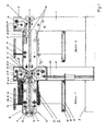
- eine Seitenansicht einer Doppelstation, wobei die erste Station im Schnitt und die zweite Station in der Seitenansicht dargestellt ist,
- Fig. 2
- die Frontansicht einer Station,
- Fig. 3
- das Prinzip der Vorseparierung über Walkeffekt,
- Fig. 4
- eine automatische Nachlademöglichkeit für die oberen Magazine mit Zufuhr von Stapeln im Bereitschaftszustand und
- Fig. 5
- die automatische Nachladung beim Ablegen des Stapels
- Fig. 1
- a side view of a dual station, the first station in section and the second station is shown in side view,
- Fig. 2
- the front view of a station,
- Fig. 3
- the principle of pre-separation via Walkteffekt,
- Fig. 4
- an automatic recharging option for the upper magazines with supply of stacks in standby mode and
- Fig. 5
- the automatic recharging when placing the stack
Eine Doppelstation mit zwei oberen und zwei unteren Magazinen besteht aus den unteren Seitenwänden 1, die über Träger 2 miteinander verbunden sind, den oberen Seitenplatten 4, die gegenüber den unteren Seitenwänden 1 in der Höhe auf Blockdicke in an sich bekannter, nicht dargestellter Weise auf Formatdicke verstellbar sind, und den zwei oberen und zwei unteren Vereinzelungseinheiten 5.A double station with two upper and two lower magazines consists of the
Sie sind passend zur Blockbreite verstellbar, so dass sie immer nahe am Rand es Bogens wirken. Sie sind dabei auf Führungen 10 zwischen den Seitenwänden 1 bzw. den oberen Seitenplatten 4 geführt. Die Verstellung erfolgt in nicht dargestellter Weise über Gewindespindeln.They are adjustable to match the block width, so they always look close to the edge of the bow. They are guided on
Die Vereinzelungseinheiten 5 enthalten Haupttransportriemen 6, Trennkeil 12, Transportriemen 15 für den Auszug, Transportriemen 22 als Gegenriemen, Teleskopsauger 30 mit Ansteuerung.The
Die Haupttransportriemen 6 mit den Umlenkrädern 7 und 8 transportieren den Teilblock von Station zu Station, wo dann jeweils ein Druckbogen von unten und/oder oben zugeführt wird. Das Umlenkrad 8 ist kontinuierlich angetrieben, wobei die Kraftübertragung durch eine Vielkeilwelle 9 erfolgt.The main transport belt 6 with the
Der Trennkeil 12 wird durch die Steuerkurve 13 in den Spalt zwischen vereinzeltem Bogen und Stapel eingeschwenkt, um einerseits den an den Ecken durch die Teleskopsauger 30 abgekippten Bogen auf ganzer Breite parallel abzukippen und um andererseits beim Abziehen des Bogens gegen die auf den Stapel wirkenden Reibungskräfte ein Mitziehen des nächsten Bogens zu vermeiden.The separating
Im Unterschied zu den als Stand der Technik bekannten Trennkeilen ist die Vorderkante des Trennkeiles 12 gegenüber der vorderen Druckbogenkante schräg verlaufend. Der Trennkeil 12 dringt dadurch zuerst dicht neben dem Teleskopsauger 30 ein, wo ein definierter Vereinzelungsspalt zwischen Stapel und Druckbogen gewährleistet ist, und schält sich dann auf dem Weg des Eindringens zwischen Stapel und Druckbogen. Die Bewegung erfolgt nicht waagerecht, sondern mit einem Winkel zur Horizontalen, der in etwa dem halben Abkippwinkel des Bogens beim Vereinzeln entspricht. Der Keilwinkel des Trennkeiles 12 nimmt zu, je weiter die Vorderkante zurück liegt, so dass die Unterkante des Trennkeiles 12 parallel zur Druckbogenvorderkante verläuft und im eingedrungenen Zustand der Trennkeil 12 den Druckbogen dann parallel abkippt. Für die dem abgekippten Bogen zugewandte Seite des Trennkeils 12 ergibt sich dabei eine verdrehte Oberfläche.In contrast to the separation wedges known as prior art, the front edge of the separating
Im Trennkeil 12 ist das vordere Umlenkrad 16 des Transportriemens 15 gelagert. Der Durchmesser ist klein, damit es weit in den Vereinzelungsspalt reicht. Angetrieben wir der Transportriemen 15 durch das Rad 17 und die Vielkeilwelle 18. Zur Längenkompensation aufgrund des Einschwenkhubes des Trennkeils 12 und damit des Umlenkrades 16 wird der Transportriemen 15 durch die Spannrolle 19 und das obere Umlenkrad 20 straff gehalten.In the separating
Auf den letzten Teil des Hubes wird durch Kurvensteuerung der Trennkeil 12 so gesteuert, dass das Umlenkrad 16 Kontakt mit dem Transportriemen 22 bekommt. Dieser ist gegenüber dem Transportriemen 15 angeordnet. Der abzuziehende Bogen wird zwischen den Transportriemen 15 und 22 eingespannt. Während der Trennkeil 12 vorfährt und den vereinzelten Bogen spannt, erfolgt kein Antrieb über die Vielkeilwelle 18. Zum Vorgang des Abziehens startet der Antrieb des Transportriemenpaares 15,22, läuft synchron zum Haupttransportriemen 6 und bringt den neuen Bogen und den schon bestehenden Teilblock deckungsgleich zusammen. Der Antrieb der Vielkeilwelle 18 kann z.B. in an sich bekannter Weise durch einen Servoantrieb oder ein Stillstandsgetriebe erfolgen.In the last part of the stroke is controlled by cam control of the separating
Der Transportriemen 22 läuft dafür gegen eine feste Schiene, der Transportriemen 15 gegen eine elastische Schiene, deren Federkraft die Anpresskraft für den Druckbogen beim Abziehen bestimmt.For this, the transport belt 22 runs against a fixed rail, the
Der Transportriemen 22 wird durch das Rad 23 umgelenkt und durch das Rad 24 angetrieben. Das Rad 24 wird vom Rad 17 des Transportriemens 15 über ein Stirnradpaar angetrieben, so dass Transportriemen 15 und Transportriemen 22 synchron zueinander laufen.The transport belt 22 is deflected by the wheel 23 and driven by the
Das Rad 24 für den Antrieb liegt deckungsgleich zum Umlenkrad 8 des Haupttransportriemens 6. Damit die Lücke zwischen den Wirkungsbereichen der Haupttransportriemen 6 klein bleibt, muss der Durchmesser des Umlenkrades 8 und des Rades 24 klein sein.The
Der bereits zusammengetragene Teilstapel wird eingespannt von den Haupttransportriemen 6 deckungsgleich mit den vereinzelten Bogen aus den Transportriemen 15 und 22 über die Lücke L in die Haupttransportriemen 6 der nächsten Station übergeben. Dazu muss das Format größer als die Lücke L sein.The already collected partial stack is clamped by the main transport belt 6 congruent with the isolated sheet from the
Die Vereinzelung erfolgt an der rechten und linken Bogenecke durch Teleskopsauger 30 gleichzeitig. Der Teleskopsauger 30 macht eine Schwenkbewegung gesteuert durch das Kurvenstück 31 , wobei der Teleskopsauger 30 über die Laufrolle 32 geführt ist. Die Bewegung wird erzeugt über die Kurvenscheibe 33, die koaxial zur Steuerkurve 13 von der kontinuierlich 1:1 laufenden Vielkeilwelle 34 angetrieben wird. Der Hub der Kurvenscheibe 33 wird durch ein Gestänge 35 auf die Teleskopsauger übertragen.The separation takes place at the right and left corner of the sheet by
In den oberen Magazinen liegen die Lagenstapel auf dem Tisch 40 auf, der vorn so weit verkürzt ist, dass die Teleskopsauger 30 die Bogenvorderkante abkippen können.In the upper magazines, the stack of layers are on the table 40, the front is so far shortened that the
Die Position des Stapels wird gehalten durch die Vorderanschläge 41, die sich an den verstellbaren Vereinzelungseinheiten 5 befinden, und die über die ganze Formatbreite reichenden Hinteranschläge 42. Letztere sind in Formathöhe in nicht dargestellter Weise beispielsweise über Stellspindeln einstellbar. Anschläge (nicht dargestellt) zur seitlichen Fixierung des Stapels befinden sich an den Vereinzelungseinheiten 5.The position of the stack is held by the front stops 41, which are located on the
Die Beladehöhe der oberen Magazine ist materialabhängig begrenzt, weil der vereinzelte unterste Bogen unter der Gewichtsbelastung des Stapels zwischen diesem und dem Tisch 40 herausgezogen werden muss.The loading height of the upper magazines is limited depending on the material, because the occasional lowermost sheet under the weight load of the stack between this and the table 40 has to be pulled out.
In den unteren Magazinen liegt der Bogenstapel auf einer Platte 50 auf, die über Führungsschienen 51 auf dem Hubtisch 52 befestigt ist und seitlich um den Betrag der maximalen Formatbreite herausziehbar ist. Dadurch kann das Beladen außerhalb des Maschinenumrisses und dadurch ohne jede Behinderung erfolgen.In the lower magazines, the sheet stack rests on a
Die unteren Magazine verfügen über eine große Kapazität und müssen nur selten nachgeladen werden.The lower magazines have a large capacity and rarely need recharging.
Die Hubtische 52 werden durch zwei Spindeltriebe 53 und 53a, einer rechts und einer links, an der rechten und linken Seite separat verstellt, um Unterschiede in der Stapelhöhe durch Druckfarbenaufbau zu kompensieren und an den Saugerpositionen immer für die exakte Höhe zu sorgen. Die Niveauregelung der Hubtische erfolgt in bekannter Art.The lifting tables 52 are adjusted separately by two spindle drives 53 and 53a, one on the right and one on the left and on the left and on the left side, in order to compensate for differences in stacking height due to ink build-up and to always ensure the exact height at the suction positions. The level control of the lifting tables takes place in a known manner.
Zur Verbesserung der Vereinzelungssicherheit erfolgt eine Vorseparierung über die Walkwalzen 60 und 61. Im oberen Magazin wird der Kontaktdruck zwischen Stapel und Walkwalze 60 durch das Gewicht des Stapels erzeugt. Im unteren Magazin liegt die Walkwalze 61 mit ihrem Gewicht auf. Die Walkwalze 61 rollt (siehe
Die Walkwalze 61 ist frei laufend mit Lagerbuchse 63 auf einer Welle 62 gelagert. Die Welle 62 hat einen exzentrischen Lagerzapfen 62a und wird kontinuierlich 1:1 angetrieben. Die Walkwalze 61 beschreibt dabei eine kreisförmige Bewegung mit einem Radius von e = ca. 5 mm. Auf einem Teil der Kreisbewegung rollt sie dabei am Stapel ab. Beim rückwärtigen Bereich der Kreisbewegung gibt es keinen Kontakt zum Stapel. Bei der vorlaufenden Bewegung mit Abrollen wird der Stapel dabei bei den oberen Magazinen um das Maß a angehoben.The
Bei den unteren Magazinen, wo die Oberfläche des Stapels nicht durch Anheben ausweichen kann, hebt sich die Walkwalze 61 mit ihrem Gewicht und einer zusätzlichen Federkraft beim Abrollen um das Maß a an. Beim rücklaufenden Teil der Bewegung lüftet die Walkwalze 61 gegenüber der Stapeloberfläche um das Maß b.In the lower magazines, where the surface of the stack can not escape by lifting, the
Die Verschiebung erfolgt in Abrollrichtung der Walkwalze am Stapel.The shift takes place in the unwinding direction of the Walkwalze on the stack.
Wie in
Alternativ ist auch vorstellbar, den Stapel von einem über das Magazin gefahrenen Blech abzuschieben, wie in
Claims (12)
- Collating machine having at least two stations located side by side, each of which stocks a stack of identical printed sheets, and a conveyance which connects all the stations, wherein a printed sheet is fed from each station to the part-block already collated, and which conveyance delivers the ready-collated block at its end,
characterised in that
each station contains two magazines, each of which stocks a printed sheet of the book and which are arranged one above the other, and that the printed sheets are selectively isolated, drawn off and fed to the common conveyance from above from the lower magazine, from below from the upper magazine or simultaneously from the lower and upper magazines. - Collating machine according to Claim 1,
characterised in that
isolation of the lowermost sheet takes place downwards in the upper magazines and isolation of the uppermost sheet takes place upwards in the lower magazines. - Collating machine according to Claim 1 or 2,
characterised in that
isolation takes place via vacuum suction cups at the front corner, viewed in the direction of conveyance, on the right and left sides in each case. - Collating machine according to Claim 3,
characterised in that
the vacuum suction cups are constructed as telescopic suction cups (30) which, on making contact with the printed sheet, achieve pre-separation of said printed sheet from the stack at the left-hand and right-hand front corners by means of their small gathering stroke. - Collating machine according to either of Claims 3 or 4,
characterised in that
a separating wedge (12) can be introduced into the isolating gap between the printed sheet isolated by the vacuum suction cup and the stack and, in the process, tilts the front edge of the quire, from the corners, to an angle of preferably 25°. - Collating machine according to one of Claims 1 to 5,
characterised in that
the tilted edge, which is the front edge viewed in the direction of conveyance, of the isolated printed sheet is grasped by preferably two pairs of conveying belts (15, 22) per magazine as a result of being gripped between said belts, and the particular sheet is then drawn out of the magazine in the direction of movement of the main conveyance, under which circumstances the conveying belts (15, 22) are at a standstill when they grip the tilted part of the sheet, and then draw off said sheet at a speed synchronised with the main conveyance and transfer it to said main conveyance. - Collating machine according to Claims 5 and 6,
characterised in that
the front deflecting wheels (16) of one of the conveying belts (15) belonging to the pair of conveying belts are located in the separating wedge (12) and are pivoted, with the latter, into the gap between the tilted printed sheet and the stack and are pressed, over the last part of the pivoting-in movement, against the other conveying belt (22) belonging to the pair of conveying belts via a control cam and, in the process, grip the printed sheet. - Collating machine according to Claim 1,
characterised in that
the main conveyance between the stations takes place in each station by means of preferably two main conveying belts (6) which consist of upper and lower belts which are driven in a continuous manner and convey the partially collated block from station to station and which undergo an interruption in each station, as a result of which a further printed sheet can be fed to the part-blook from above and/or below in the course of conveyance. - Collating machine according to Claim 1,
characterised in that
the elements for isolation, drawing-off and conveyance to the next station are accommodated in compact units, of which two are located in the upper magazine and two in the lower magazine and which can be adjusted as a whole unit, format-wise, on the right and left to the outer edges of the printed sheet. - Collating machine according to Claim 3 or 4,
characterised in that
the lifting tables (52) for the lower magazine have a separate level-regulating system on the left and right sides for the purpose of optimal adaptation of the upper edge of the stack to the position of the vacuum suction cups. - Collating machine according to Claim 9,
characterised in that
there is located, on each lifting table, a plate (50) on which the material lies and which can be extended laterally on guide rails (51) on the lifting table (52) for the purpose of effecting loading outside the frame of the machine. - Collating machine according to Claim 1,
characterised in that
the upper magazine having a low admissible loading height can be subjected to subsequent loading with stacks of low height by means of a laterally displaceable band (71), through the fact that said band (71) can be brought, with a stack laid on it, across the magazine with the band (71) locked in position in relation to the framework (70) of the band, and then retracted again with the band (71) locked in position in relation to the frame of the machine, under which circumstances the new stack rolls off onto the existing residual stack in a congruent manner.
Applications Claiming Priority (2)
| Application Number | Priority Date | Filing Date | Title |
|---|---|---|---|
| DE102010033434A DE102010033434A1 (en) | 2010-08-04 | 2010-08-04 | Collator |
| PCT/DE2011/001484 WO2012016562A1 (en) | 2010-08-04 | 2011-07-21 | Collating machine |
Publications (2)
| Publication Number | Publication Date |
|---|---|
| EP2609025A1 EP2609025A1 (en) | 2013-07-03 |
| EP2609025B1 true EP2609025B1 (en) | 2014-02-19 |
Family
ID=44735760
Family Applications (1)
| Application Number | Title | Priority Date | Filing Date |
|---|---|---|---|
| EP11764082.1A Not-in-force EP2609025B1 (en) | 2010-08-04 | 2011-07-21 | Collating machine |
Country Status (3)
| Country | Link |
|---|---|
| EP (1) | EP2609025B1 (en) |
| DE (2) | DE102010033434A1 (en) |
| WO (1) | WO2012016562A1 (en) |
Families Citing this family (2)
| Publication number | Priority date | Publication date | Assignee | Title |
|---|---|---|---|---|
| CN102658993B (en) * | 2012-05-11 | 2015-07-22 | 浙江新华数码印务有限公司 | Section acceleration device of high-speed roller type automatic assembling machine and assembling machine |
| DE102016217043B4 (en) * | 2016-09-07 | 2019-02-14 | Bundesdruckerei Gmbh | Compact gathering device for creating a material sheet booklet |
Citations (1)
| Publication number | Priority date | Publication date | Assignee | Title |
|---|---|---|---|---|
| JP2007119123A (en) * | 2005-10-26 | 2007-05-17 | Canon Inc | Image forming system |
Family Cites Families (16)
| Publication number | Priority date | Publication date | Assignee | Title |
|---|---|---|---|---|
| DE1919418A1 (en) | 1969-04-17 | 1970-10-29 | Kuepper Und Ruhrberg Gmbh & Co | Gathering machine for sets of forms and the like. |
| CH586611A5 (en) | 1975-11-14 | 1977-04-15 | Grapha Holding Ag | |
| CH635046A5 (en) | 1978-11-17 | 1983-03-15 | Grapha Holding Ag | COLLECTOR FOR PRINTED SHEET. |
| JPS57170348A (en) * | 1981-04-11 | 1982-10-20 | Tomio Kishida | Gathering machine |
| DE3126789A1 (en) | 1981-07-07 | 1983-01-27 | G + H Montage Gmbh, 6700 Ludwigshafen | Refrigeration ship |
| JPS5839392A (en) * | 1981-09-02 | 1983-03-08 | ロ−レルバンクマシン株式会社 | Stacker supporting unit for automatic teller machine |
| EP0207778A3 (en) | 1985-07-03 | 1988-06-15 | Portals Engineering Limited | Gathering machine |
| JP2716384B2 (en) | 1994-11-25 | 1998-02-18 | 忠男 宇野 | Sheet bundle flat stacking device |
| DE19616047C5 (en) | 1996-04-23 | 2011-04-21 | Kolbus Gmbh & Co. Kg | Collator |
| EP1498282B1 (en) * | 2003-07-17 | 2012-03-28 | Wohlenberg Buchbindesysteme GmbH | Method and apparatus for collating printed products |
| JP4249649B2 (en) | 2004-04-09 | 2009-04-02 | ホリゾン・インターナショナル株式会社 | Vertical collating machine |
| DE102004053737A1 (en) * | 2004-11-06 | 2006-05-18 | Kolbus Gmbh & Co. Kg | Method and device for inserting and / or inserting pressure supplements into main printed products |
| JP2006202022A (en) * | 2005-01-20 | 2006-08-03 | Canon Inc | Rearrangement device |
| EP1686084B1 (en) * | 2005-01-31 | 2011-06-15 | Müller Martini Holding AG | Device for gathering printed sheets along a conveying route of a circulating conveyer |
| DE102005035332B4 (en) * | 2005-07-28 | 2015-08-06 | Kolbus Gmbh & Co. Kg | Apparatus for gathering printed sheets |
| US20080257799A1 (en) * | 2007-04-20 | 2008-10-23 | Seidel Randy R | Apparatus & method for high speed document collation for insert into newspaper and other printed media |
-
2010
- 2010-08-04 DE DE102010033434A patent/DE102010033434A1/en not_active Withdrawn
-
2011
- 2011-07-21 EP EP11764082.1A patent/EP2609025B1/en not_active Not-in-force
- 2011-07-21 DE DE112011104099T patent/DE112011104099A5/en not_active Withdrawn
- 2011-07-21 WO PCT/DE2011/001484 patent/WO2012016562A1/en active Application Filing
Patent Citations (1)
| Publication number | Priority date | Publication date | Assignee | Title |
|---|---|---|---|---|
| JP2007119123A (en) * | 2005-10-26 | 2007-05-17 | Canon Inc | Image forming system |
Also Published As
| Publication number | Publication date |
|---|---|
| WO2012016562A1 (en) | 2012-02-09 |
| DE102010033434A1 (en) | 2012-02-09 |
| EP2609025A1 (en) | 2013-07-03 |
| DE112011104099A5 (en) | 2013-11-28 |
Similar Documents
| Publication | Publication Date | Title |
|---|---|---|
| DE3203506A1 (en) | DEVICE FOR INSERTING SHEET PACKAGES INTO A MACHINING MACHINE | |
| DE102006028381A1 (en) | Flat parts e.g. paper sheets, stack forming method, involves withdrawing auxiliary stack carrier from stack areas to deliver partial stack formed on auxiliary stack carrier, and moving upper side of section of main stack | |
| EP2253566B1 (en) | Device for feeding a processing line with printed products | |
| DE10057599C5 (en) | Device for making book covers | |
| EP1622778B1 (en) | Device for inserting sheets into an envelope | |
| CH695770A5 (en) | Book cover machine for producing book cases. | |
| DE2824304C2 (en) | Transport device for transferring folding box blanks from a printing and punching machine to a folding and gluing machine | |
| EP2133295B1 (en) | Device and method for removing flat print products from a pile and transferring the print products to a running transport device | |
| EP2609025B1 (en) | Collating machine | |
| DE1436064C3 (en) | Device for gathering folded sheets into a book block | |
| EP0451091B1 (en) | Sheet feeder | |
| DE3219693A1 (en) | Device for forming processable partial piles from film sheets, in particular paper sheets | |
| EP0845431B1 (en) | Method and device for a piling device of a printing machine | |
| WO2009141119A2 (en) | Apparatus for forming stacked packs | |
| EP1748012B1 (en) | Method and device for collecting sheets | |
| EP1593633B1 (en) | Device for piling printing products | |
| DE2720599A1 (en) | SHEET FEED DEVICE FOR A ROTARY PRINTING MACHINE WITH A SIDE PULLING DEVICE | |
| EP1398286B1 (en) | Method and device for processing and separating a shingled formation of flat and flexible articles | |
| EP1424301B1 (en) | Method and device for stacking sheet material | |
| DE2038219C3 (en) | Automatic pile feeder | |
| DE102009022249B4 (en) | Transfer device for transferring a stack formed by a plurality of sheet layers | |
| DE102022122393A1 (en) | Variable sheet feed | |
| DE4213220A1 (en) | Simple and economical binding machine for book pages or documents - incorporates alignment mechanism for paper sheets and rollers picking up sheets to mate them up with binding boards | |
| EP1274641A1 (en) | Method and device for forming piles of sheets consisting of one or more sheets | |
| CH682484A5 (en) | Loader for binding or stapling machine magazine - uses delivery conveyor within adjustable frame providing stacked sheet sets in magazine from overlapping sheet flow |
Legal Events
| Date | Code | Title | Description |
|---|---|---|---|
| PUAI | Public reference made under article 153(3) epc to a published international application that has entered the european phase |
Free format text: ORIGINAL CODE: 0009012 |
|
| 17P | Request for examination filed |
Effective date: 20120518 |
|
| AK | Designated contracting states |
Kind code of ref document: A1 Designated state(s): AL AT BE BG CH CY CZ DE DK EE ES FI FR GB GR HR HU IE IS IT LI LT LU LV MC MK MT NL NO PL PT RO RS SE SI SK SM TR |
|
| GRAP | Despatch of communication of intention to grant a patent |
Free format text: ORIGINAL CODE: EPIDOSNIGR1 |
|
| RIC1 | Information provided on ipc code assigned before grant |
Ipc: B65H 3/04 20060101ALI20130826BHEP Ipc: B65H 1/06 20060101ALI20130826BHEP Ipc: B65H 39/042 20060101AFI20130826BHEP Ipc: B65H 39/043 20060101ALI20130826BHEP Ipc: B42C 1/12 20060101ALI20130826BHEP Ipc: B65H 5/02 20060101ALI20130826BHEP Ipc: B65H 3/50 20060101ALI20130826BHEP Ipc: B65H 1/14 20060101ALI20130826BHEP Ipc: B65H 3/08 20060101ALI20130826BHEP |
|
| DAX | Request for extension of the european patent (deleted) | ||
| INTG | Intention to grant announced |
Effective date: 20130909 |
|
| GRAS | Grant fee paid |
Free format text: ORIGINAL CODE: EPIDOSNIGR3 |
|
| GRAA | (expected) grant |
Free format text: ORIGINAL CODE: 0009210 |
|
| AK | Designated contracting states |
Kind code of ref document: B1 Designated state(s): AL AT BE BG CH CY CZ DE DK EE ES FI FR GB GR HR HU IE IS IT LI LT LU LV MC MK MT NL NO PL PT RO RS SE SI SK SM TR |
|
| REG | Reference to a national code |
Ref country code: GB Ref legal event code: FG4D Free format text: NOT ENGLISH |
|
| REG | Reference to a national code |
Ref country code: CH Ref legal event code: EP |
|
| REG | Reference to a national code |
Ref country code: AT Ref legal event code: REF Ref document number: 652780 Country of ref document: AT Kind code of ref document: T Effective date: 20140315 |
|
| REG | Reference to a national code |
Ref country code: DE Ref legal event code: R096 Ref document number: 502011002174 Country of ref document: DE Effective date: 20140403 |
|
| REG | Reference to a national code |
Ref country code: IE Ref legal event code: FG4D Free format text: LANGUAGE OF EP DOCUMENT: GERMAN |
|
| REG | Reference to a national code |
Ref country code: NL Ref legal event code: VDEP Effective date: 20140219 |
|
| REG | Reference to a national code |
Ref country code: LT Ref legal event code: MG4D |
|
| PG25 | Lapsed in a contracting state [announced via postgrant information from national office to epo] |
Ref country code: NO Free format text: LAPSE BECAUSE OF FAILURE TO SUBMIT A TRANSLATION OF THE DESCRIPTION OR TO PAY THE FEE WITHIN THE PRESCRIBED TIME-LIMIT Effective date: 20140519 Ref country code: IS Free format text: LAPSE BECAUSE OF FAILURE TO SUBMIT A TRANSLATION OF THE DESCRIPTION OR TO PAY THE FEE WITHIN THE PRESCRIBED TIME-LIMIT Effective date: 20140619 Ref country code: LT Free format text: LAPSE BECAUSE OF FAILURE TO SUBMIT A TRANSLATION OF THE DESCRIPTION OR TO PAY THE FEE WITHIN THE PRESCRIBED TIME-LIMIT Effective date: 20140219 |
|
| PG25 | Lapsed in a contracting state [announced via postgrant information from national office to epo] |
Ref country code: NL Free format text: LAPSE BECAUSE OF FAILURE TO SUBMIT A TRANSLATION OF THE DESCRIPTION OR TO PAY THE FEE WITHIN THE PRESCRIBED TIME-LIMIT Effective date: 20140219 Ref country code: CY Free format text: LAPSE BECAUSE OF FAILURE TO SUBMIT A TRANSLATION OF THE DESCRIPTION OR TO PAY THE FEE WITHIN THE PRESCRIBED TIME-LIMIT Effective date: 20140219 Ref country code: SE Free format text: LAPSE BECAUSE OF FAILURE TO SUBMIT A TRANSLATION OF THE DESCRIPTION OR TO PAY THE FEE WITHIN THE PRESCRIBED TIME-LIMIT Effective date: 20140219 Ref country code: FI Free format text: LAPSE BECAUSE OF FAILURE TO SUBMIT A TRANSLATION OF THE DESCRIPTION OR TO PAY THE FEE WITHIN THE PRESCRIBED TIME-LIMIT Effective date: 20140219 Ref country code: ES Free format text: LAPSE BECAUSE OF FAILURE TO SUBMIT A TRANSLATION OF THE DESCRIPTION OR TO PAY THE FEE WITHIN THE PRESCRIBED TIME-LIMIT Effective date: 20140219 Ref country code: PT Free format text: LAPSE BECAUSE OF FAILURE TO SUBMIT A TRANSLATION OF THE DESCRIPTION OR TO PAY THE FEE WITHIN THE PRESCRIBED TIME-LIMIT Effective date: 20140619 |
|
| PG25 | Lapsed in a contracting state [announced via postgrant information from national office to epo] |
Ref country code: RS Free format text: LAPSE BECAUSE OF FAILURE TO SUBMIT A TRANSLATION OF THE DESCRIPTION OR TO PAY THE FEE WITHIN THE PRESCRIBED TIME-LIMIT Effective date: 20140219 Ref country code: HR Free format text: LAPSE BECAUSE OF FAILURE TO SUBMIT A TRANSLATION OF THE DESCRIPTION OR TO PAY THE FEE WITHIN THE PRESCRIBED TIME-LIMIT Effective date: 20140219 Ref country code: LV Free format text: LAPSE BECAUSE OF FAILURE TO SUBMIT A TRANSLATION OF THE DESCRIPTION OR TO PAY THE FEE WITHIN THE PRESCRIBED TIME-LIMIT Effective date: 20140219 |
|
| PG25 | Lapsed in a contracting state [announced via postgrant information from national office to epo] |
Ref country code: DK Free format text: LAPSE BECAUSE OF FAILURE TO SUBMIT A TRANSLATION OF THE DESCRIPTION OR TO PAY THE FEE WITHIN THE PRESCRIBED TIME-LIMIT Effective date: 20140219 Ref country code: RO Free format text: LAPSE BECAUSE OF FAILURE TO SUBMIT A TRANSLATION OF THE DESCRIPTION OR TO PAY THE FEE WITHIN THE PRESCRIBED TIME-LIMIT Effective date: 20140219 Ref country code: CZ Free format text: LAPSE BECAUSE OF FAILURE TO SUBMIT A TRANSLATION OF THE DESCRIPTION OR TO PAY THE FEE WITHIN THE PRESCRIBED TIME-LIMIT Effective date: 20140219 Ref country code: EE Free format text: LAPSE BECAUSE OF FAILURE TO SUBMIT A TRANSLATION OF THE DESCRIPTION OR TO PAY THE FEE WITHIN THE PRESCRIBED TIME-LIMIT Effective date: 20140219 |
|
| REG | Reference to a national code |
Ref country code: DE Ref legal event code: R097 Ref document number: 502011002174 Country of ref document: DE |
|
| PG25 | Lapsed in a contracting state [announced via postgrant information from national office to epo] |
Ref country code: SK Free format text: LAPSE BECAUSE OF FAILURE TO SUBMIT A TRANSLATION OF THE DESCRIPTION OR TO PAY THE FEE WITHIN THE PRESCRIBED TIME-LIMIT Effective date: 20140219 Ref country code: PL Free format text: LAPSE BECAUSE OF FAILURE TO SUBMIT A TRANSLATION OF THE DESCRIPTION OR TO PAY THE FEE WITHIN THE PRESCRIBED TIME-LIMIT Effective date: 20140219 |
|
| PLBE | No opposition filed within time limit |
Free format text: ORIGINAL CODE: 0009261 |
|
| STAA | Information on the status of an ep patent application or granted ep patent |
Free format text: STATUS: NO OPPOSITION FILED WITHIN TIME LIMIT |
|
| 26N | No opposition filed |
Effective date: 20141120 |
|
| PG25 | Lapsed in a contracting state [announced via postgrant information from national office to epo] |
Ref country code: RS Free format text: LAPSE BECAUSE OF FAILURE TO SUBMIT A TRANSLATION OF THE DESCRIPTION OR TO PAY THE FEE WITHIN THE PRESCRIBED TIME-LIMIT Effective date: 20140903 Ref country code: LU Free format text: LAPSE BECAUSE OF FAILURE TO SUBMIT A TRANSLATION OF THE DESCRIPTION OR TO PAY THE FEE WITHIN THE PRESCRIBED TIME-LIMIT Effective date: 20140721 |
|
| REG | Reference to a national code |
Ref country code: CH Ref legal event code: PL |
|
| REG | Reference to a national code |
Ref country code: DE Ref legal event code: R097 Ref document number: 502011002174 Country of ref document: DE Effective date: 20141120 |
|
| PG25 | Lapsed in a contracting state [announced via postgrant information from national office to epo] |
Ref country code: IT Free format text: LAPSE BECAUSE OF FAILURE TO SUBMIT A TRANSLATION OF THE DESCRIPTION OR TO PAY THE FEE WITHIN THE PRESCRIBED TIME-LIMIT Effective date: 20140219 |
|
| REG | Reference to a national code |
Ref country code: IE Ref legal event code: MM4A |
|
| PG25 | Lapsed in a contracting state [announced via postgrant information from national office to epo] |
Ref country code: CH Free format text: LAPSE BECAUSE OF NON-PAYMENT OF DUE FEES Effective date: 20140731 Ref country code: LI Free format text: LAPSE BECAUSE OF NON-PAYMENT OF DUE FEES Effective date: 20140731 |
|
| PG25 | Lapsed in a contracting state [announced via postgrant information from national office to epo] |
Ref country code: SI Free format text: LAPSE BECAUSE OF FAILURE TO SUBMIT A TRANSLATION OF THE DESCRIPTION OR TO PAY THE FEE WITHIN THE PRESCRIBED TIME-LIMIT Effective date: 20140219 |
|
| REG | Reference to a national code |
Ref country code: FR Ref legal event code: PLFP Year of fee payment: 5 |
|
| PG25 | Lapsed in a contracting state [announced via postgrant information from national office to epo] |
Ref country code: IE Free format text: LAPSE BECAUSE OF NON-PAYMENT OF DUE FEES Effective date: 20140721 |
|
| PGFP | Annual fee paid to national office [announced via postgrant information from national office to epo] |
Ref country code: GB Payment date: 20150707 Year of fee payment: 5 |
|
| PGFP | Annual fee paid to national office [announced via postgrant information from national office to epo] |
Ref country code: FR Payment date: 20150716 Year of fee payment: 5 |
|
| PG25 | Lapsed in a contracting state [announced via postgrant information from national office to epo] |
Ref country code: SM Free format text: LAPSE BECAUSE OF FAILURE TO SUBMIT A TRANSLATION OF THE DESCRIPTION OR TO PAY THE FEE WITHIN THE PRESCRIBED TIME-LIMIT Effective date: 20140219 Ref country code: MC Free format text: LAPSE BECAUSE OF FAILURE TO SUBMIT A TRANSLATION OF THE DESCRIPTION OR TO PAY THE FEE WITHIN THE PRESCRIBED TIME-LIMIT Effective date: 20140219 |
|
| PG25 | Lapsed in a contracting state [announced via postgrant information from national office to epo] |
Ref country code: BG Free format text: LAPSE BECAUSE OF FAILURE TO SUBMIT A TRANSLATION OF THE DESCRIPTION OR TO PAY THE FEE WITHIN THE PRESCRIBED TIME-LIMIT Effective date: 20140219 Ref country code: MT Free format text: LAPSE BECAUSE OF FAILURE TO SUBMIT A TRANSLATION OF THE DESCRIPTION OR TO PAY THE FEE WITHIN THE PRESCRIBED TIME-LIMIT Effective date: 20140219 Ref country code: GR Free format text: LAPSE BECAUSE OF FAILURE TO SUBMIT A TRANSLATION OF THE DESCRIPTION OR TO PAY THE FEE WITHIN THE PRESCRIBED TIME-LIMIT Effective date: 20140520 |
|
| PG25 | Lapsed in a contracting state [announced via postgrant information from national office to epo] |
Ref country code: BE Free format text: LAPSE BECAUSE OF FAILURE TO SUBMIT A TRANSLATION OF THE DESCRIPTION OR TO PAY THE FEE WITHIN THE PRESCRIBED TIME-LIMIT Effective date: 20140731 Ref country code: TR Free format text: LAPSE BECAUSE OF FAILURE TO SUBMIT A TRANSLATION OF THE DESCRIPTION OR TO PAY THE FEE WITHIN THE PRESCRIBED TIME-LIMIT Effective date: 20140219 Ref country code: HU Free format text: LAPSE BECAUSE OF FAILURE TO SUBMIT A TRANSLATION OF THE DESCRIPTION OR TO PAY THE FEE WITHIN THE PRESCRIBED TIME-LIMIT; INVALID AB INITIO Effective date: 20110721 |
|
| GBPC | Gb: european patent ceased through non-payment of renewal fee |
Effective date: 20160721 |
|
| PG25 | Lapsed in a contracting state [announced via postgrant information from national office to epo] |
Ref country code: FR Free format text: LAPSE BECAUSE OF NON-PAYMENT OF DUE FEES Effective date: 20160801 |
|
| REG | Reference to a national code |
Ref country code: FR Ref legal event code: ST Effective date: 20170331 |
|
| PG25 | Lapsed in a contracting state [announced via postgrant information from national office to epo] |
Ref country code: GB Free format text: LAPSE BECAUSE OF NON-PAYMENT OF DUE FEES Effective date: 20160721 |
|
| PGFP | Annual fee paid to national office [announced via postgrant information from national office to epo] |
Ref country code: DE Payment date: 20170511 Year of fee payment: 7 |
|
| PGFP | Annual fee paid to national office [announced via postgrant information from national office to epo] |
Ref country code: AT Payment date: 20170727 Year of fee payment: 7 |
|
| PG25 | Lapsed in a contracting state [announced via postgrant information from national office to epo] |
Ref country code: MK Free format text: LAPSE BECAUSE OF FAILURE TO SUBMIT A TRANSLATION OF THE DESCRIPTION OR TO PAY THE FEE WITHIN THE PRESCRIBED TIME-LIMIT Effective date: 20140219 |
|
| PG25 | Lapsed in a contracting state [announced via postgrant information from national office to epo] |
Ref country code: AL Free format text: LAPSE BECAUSE OF FAILURE TO SUBMIT A TRANSLATION OF THE DESCRIPTION OR TO PAY THE FEE WITHIN THE PRESCRIBED TIME-LIMIT Effective date: 20140219 |
|
| REG | Reference to a national code |
Ref country code: DE Ref legal event code: R119 Ref document number: 502011002174 Country of ref document: DE |
|
| REG | Reference to a national code |
Ref country code: AT Ref legal event code: MM01 Ref document number: 652780 Country of ref document: AT Kind code of ref document: T Effective date: 20180721 |
|
| PG25 | Lapsed in a contracting state [announced via postgrant information from national office to epo] |
Ref country code: DE Free format text: LAPSE BECAUSE OF NON-PAYMENT OF DUE FEES Effective date: 20190201 Ref country code: AT Free format text: LAPSE BECAUSE OF NON-PAYMENT OF DUE FEES Effective date: 20180721 |