EP2608897B1 - Générateur d'ondes mécaniques et procédé associé - Google Patents
Générateur d'ondes mécaniques et procédé associé Download PDFInfo
- Publication number
- EP2608897B1 EP2608897B1 EP11819487.7A EP11819487A EP2608897B1 EP 2608897 B1 EP2608897 B1 EP 2608897B1 EP 11819487 A EP11819487 A EP 11819487A EP 2608897 B1 EP2608897 B1 EP 2608897B1
- Authority
- EP
- European Patent Office
- Prior art keywords
- wave
- waveguide
- dispersive
- source
- medium
- Prior art date
- Legal status (The legal status is an assumption and is not a legal conclusion. Google has not performed a legal analysis and makes no representation as to the accuracy of the status listed.)
- Active
Links
- 238000000034 method Methods 0.000 title claims description 34
- 230000001419 dependent effect Effects 0.000 claims description 5
- 239000000203 mixture Substances 0.000 claims description 5
- 230000005540 biological transmission Effects 0.000 claims description 4
- 239000000919 ceramic Substances 0.000 claims description 4
- 230000002441 reversible effect Effects 0.000 claims description 4
- 230000000644 propagated effect Effects 0.000 claims description 3
- 230000001902 propagating effect Effects 0.000 claims description 3
- 238000009738 saturating Methods 0.000 claims description 2
- 239000002184 metal Substances 0.000 claims 2
- 229920006395 saturated elastomer Polymers 0.000 claims 2
- 238000004904 shortening Methods 0.000 claims 1
- 230000001131 transforming effect Effects 0.000 claims 1
- 239000006185 dispersion Substances 0.000 description 20
- 208000000913 Kidney Calculi Diseases 0.000 description 14
- 206010029148 Nephrolithiasis Diseases 0.000 description 14
- 230000006835 compression Effects 0.000 description 7
- 238000007906 compression Methods 0.000 description 7
- 238000002474 experimental method Methods 0.000 description 7
- 239000011521 glass Substances 0.000 description 6
- 239000000463 material Substances 0.000 description 6
- 239000007787 solid Substances 0.000 description 6
- 239000004593 Epoxy Substances 0.000 description 5
- XAGFODPZIPBFFR-UHFFFAOYSA-N aluminium Chemical compound [Al] XAGFODPZIPBFFR-UHFFFAOYSA-N 0.000 description 5
- 229910052782 aluminium Inorganic materials 0.000 description 5
- 230000008878 coupling Effects 0.000 description 5
- 238000010168 coupling process Methods 0.000 description 5
- 238000005859 coupling reaction Methods 0.000 description 5
- 230000000704 physical effect Effects 0.000 description 5
- 230000002123 temporal effect Effects 0.000 description 5
- 230000003321 amplification Effects 0.000 description 4
- 239000007789 gas Substances 0.000 description 4
- 239000000499 gel Substances 0.000 description 4
- 239000007788 liquid Substances 0.000 description 4
- 238000003199 nucleic acid amplification method Methods 0.000 description 4
- 239000000523 sample Substances 0.000 description 4
- XLYOFNOQVPJJNP-UHFFFAOYSA-N water Substances O XLYOFNOQVPJJNP-UHFFFAOYSA-N 0.000 description 4
- 230000006378 damage Effects 0.000 description 3
- 230000000694 effects Effects 0.000 description 3
- 230000010363 phase shift Effects 0.000 description 3
- 230000004044 response Effects 0.000 description 3
- 238000005316 response function Methods 0.000 description 3
- 230000035939 shock Effects 0.000 description 3
- 239000004575 stone Substances 0.000 description 3
- 238000002604 ultrasonography Methods 0.000 description 3
- 230000008901 benefit Effects 0.000 description 2
- 238000004364 calculation method Methods 0.000 description 2
- 238000005516 engineering process Methods 0.000 description 2
- 239000012634 fragment Substances 0.000 description 2
- 230000006872 improvement Effects 0.000 description 2
- 230000009022 nonlinear effect Effects 0.000 description 2
- 230000005855 radiation Effects 0.000 description 2
- 230000006798 recombination Effects 0.000 description 2
- 238000005215 recombination Methods 0.000 description 2
- 239000008399 tap water Substances 0.000 description 2
- 235000020679 tap water Nutrition 0.000 description 2
- 238000012546 transfer Methods 0.000 description 2
- 238000012285 ultrasound imaging Methods 0.000 description 2
- FYYHWMGAXLPEAU-UHFFFAOYSA-N Magnesium Chemical compound [Mg] FYYHWMGAXLPEAU-UHFFFAOYSA-N 0.000 description 1
- RTAQQCXQSZGOHL-UHFFFAOYSA-N Titanium Chemical compound [Ti] RTAQQCXQSZGOHL-UHFFFAOYSA-N 0.000 description 1
- 239000000956 alloy Substances 0.000 description 1
- 229910045601 alloy Inorganic materials 0.000 description 1
- 238000002399 angioplasty Methods 0.000 description 1
- 230000002238 attenuated effect Effects 0.000 description 1
- 239000012620 biological material Substances 0.000 description 1
- 230000008859 change Effects 0.000 description 1
- 238000006243 chemical reaction Methods 0.000 description 1
- 238000005253 cladding Methods 0.000 description 1
- 238000004891 communication Methods 0.000 description 1
- 239000012141 concentrate Substances 0.000 description 1
- 238000010276 construction Methods 0.000 description 1
- 238000003745 diagnosis Methods 0.000 description 1
- 238000002592 echocardiography Methods 0.000 description 1
- 230000005284 excitation Effects 0.000 description 1
- 239000012530 fluid Substances 0.000 description 1
- 238000002594 fluoroscopy Methods 0.000 description 1
- 239000003292 glue Substances 0.000 description 1
- 238000003780 insertion Methods 0.000 description 1
- 230000037431 insertion Effects 0.000 description 1
- 230000003993 interaction Effects 0.000 description 1
- 238000009533 lab test Methods 0.000 description 1
- 229910052749 magnesium Inorganic materials 0.000 description 1
- 239000011777 magnesium Substances 0.000 description 1
- 239000011159 matrix material Substances 0.000 description 1
- 238000012986 modification Methods 0.000 description 1
- 230000004048 modification Effects 0.000 description 1
- 238000009659 non-destructive testing Methods 0.000 description 1
- 230000010355 oscillation Effects 0.000 description 1
- 239000002245 particle Substances 0.000 description 1
- HTYIXCKSEQQCJO-UHFFFAOYSA-N phenaglycodol Chemical group CC(C)(O)C(C)(O)C1=CC=C(Cl)C=C1 HTYIXCKSEQQCJO-UHFFFAOYSA-N 0.000 description 1
- 239000010935 stainless steel Substances 0.000 description 1
- 229910001220 stainless steel Inorganic materials 0.000 description 1
- 239000000126 substance Substances 0.000 description 1
- 229910052719 titanium Inorganic materials 0.000 description 1
- 239000010936 titanium Substances 0.000 description 1
- 230000007704 transition Effects 0.000 description 1
Images


Classifications
-
- A—HUMAN NECESSITIES
- A61—MEDICAL OR VETERINARY SCIENCE; HYGIENE
- A61H—PHYSICAL THERAPY APPARATUS, e.g. DEVICES FOR LOCATING OR STIMULATING REFLEX POINTS IN THE BODY; ARTIFICIAL RESPIRATION; MASSAGE; BATHING DEVICES FOR SPECIAL THERAPEUTIC OR HYGIENIC PURPOSES OR SPECIFIC PARTS OF THE BODY
- A61H1/00—Apparatus for passive exercising; Vibrating apparatus; Chiropractic devices, e.g. body impacting devices, external devices for briefly extending or aligning unbroken bones
-
- A—HUMAN NECESSITIES
- A61—MEDICAL OR VETERINARY SCIENCE; HYGIENE
- A61B—DIAGNOSIS; SURGERY; IDENTIFICATION
- A61B17/00—Surgical instruments, devices or methods, e.g. tourniquets
- A61B17/22—Implements for squeezing-off ulcers or the like on the inside of inner organs of the body; Implements for scraping-out cavities of body organs, e.g. bones; Calculus removers; Calculus smashing apparatus; Apparatus for removing obstructions in blood vessels, not otherwise provided for
- A61B17/225—Implements for squeezing-off ulcers or the like on the inside of inner organs of the body; Implements for scraping-out cavities of body organs, e.g. bones; Calculus removers; Calculus smashing apparatus; Apparatus for removing obstructions in blood vessels, not otherwise provided for for extracorporeal shock wave lithotripsy [ESWL], e.g. by using ultrasonic waves
-
- B—PERFORMING OPERATIONS; TRANSPORTING
- B06—GENERATING OR TRANSMITTING MECHANICAL VIBRATIONS IN GENERAL
- B06B—METHODS OR APPARATUS FOR GENERATING OR TRANSMITTING MECHANICAL VIBRATIONS OF INFRASONIC, SONIC, OR ULTRASONIC FREQUENCY, e.g. FOR PERFORMING MECHANICAL WORK IN GENERAL
- B06B3/00—Methods or apparatus specially adapted for transmitting mechanical vibrations of infrasonic, sonic, or ultrasonic frequency
-
- G—PHYSICS
- G10—MUSICAL INSTRUMENTS; ACOUSTICS
- G10K—SOUND-PRODUCING DEVICES; METHODS OR DEVICES FOR PROTECTING AGAINST, OR FOR DAMPING, NOISE OR OTHER ACOUSTIC WAVES IN GENERAL; ACOUSTICS NOT OTHERWISE PROVIDED FOR
- G10K15/00—Acoustics not otherwise provided for
- G10K15/02—Synthesis of acoustic waves
-
- G—PHYSICS
- G10—MUSICAL INSTRUMENTS; ACOUSTICS
- G10K—SOUND-PRODUCING DEVICES; METHODS OR DEVICES FOR PROTECTING AGAINST, OR FOR DAMPING, NOISE OR OTHER ACOUSTIC WAVES IN GENERAL; ACOUSTICS NOT OTHERWISE PROVIDED FOR
- G10K15/00—Acoustics not otherwise provided for
- G10K15/04—Sound-producing devices
- G10K15/043—Sound-producing devices producing shock waves
Definitions
- This invention relates to devices for generating mechanical waves and methods thereof.
- a "mechanical wave” is a disturbance that propagates through a medium due to the restoring forces it produces upon deformation of the medium. Solids, liquids, gases, and gels are examples of media through which a mechanical wave may travel.
- the energy of a mechanical wave can be exploited to deform and potentially fracture an object placed in the medium.
- high intensity compression pulses i.e., a brief wave of great amplitude
- kidney stone destruction consists of emitting a compression pulse having a sufficient amount of energy for traveling through the body, reaching the stone, and potentially rupturing the kidney stone upon contact.
- Machines used in medical kidney stone destruction are known in the art as lithotripters.
- the external lithotripters send externally-applied, focused, high-intensity compression pulses toward the kidney stone.
- shockwaves encounters a non-homogeneity such as the kidney stone, a relatively large amount of energy is transferred from the shockwave to the kidney stone in a (relatively) very short period of time.
- this energy transfer is sufficient to break enough of the bonds between the stone particles to destroy the stone.
- the location of the kidney stone within the body of the patient must be known in order to direct the high-intensity compression pulses toward the kidney stone.
- US Patent No. 4,907,573 to Nagasaki entitled “Ultrasonic lithotresis apparatus” and granted on March 13, 1990 discloses a large number of piezoelectric elements arranged in a mosaic pattern on a spherical surface so that ultrasonic waves generated by the elements converge on a single point.
- the arrangement of the elements constitutes a transducer.
- ultrasonic shock waves from each piezoelectric element are concentrated on a lithotresis object, or a calculus so as to break it.
- the ultrasonic shock waves are generated by applying driving impulses (voltage) to each piezoelectric element.
- the transducer In order to locate the calculus, the transducer is coupled to an ultrasonic diagnosis apparatus having a mechanical scanning type ultrasonic probe.
- the piezoelectric elements have resonance frequencies set such that the piezoelectric element positioned at the center of the transducer has the lowest resonance frequency and the resonance frequency of each piezoelectric element is increased in accordance with its distance from the center.
- the frequency range of vibration of the transducer is broadened so that the ultrasonic shock waves become low in negative sound pressure and narrow in pulse width at the point of convergence.
- acoustic probe comprising a piezoelectric ceramic transducer element energizable to emit ultrasonic signals in a first direction and in a second direction opposite to the first, and mountable on a sample to be tested so as to transmit thereto signals emitted in the said first direction, is further provided, according to the invention, with a rod-shaped acoustic waveguide having one end coupled to the transducer element to receive signals emitted by the transducer element in the said second direction and to transmit them along the waveguide, with lossy cladding material acoustically coupled to the surface of the waveguide at least at a part thereof remote from its one end, and with coupling means surrounding and mechanically secured and acoustically coupled to the ceramic element and the said one end of the waveguide, the coupling means having a surface adapted to be secured to the sample to
- US Patent No. 5,509,417 to Dias et al. entitled “Method and apparatus for phased array coupling ultrasonic energy into an acoustic waveguide wire” and granted on April 23, 1996 (“D3”) teaches a method and apparatus for coupling ultrasonic energy into a clad or unclad waveguide which include using phased array techniques to increase the area and intensity of radiation into the waveguide.
- An array of ultrasound transducers is positioned at the exterior of the waveguide and at dissimilar distances from the end of the waveguide. The transducers are individually fired by applying separate phase-shifted excitation signals. The phase shifting achieves a selected phase-differential relationship with respect to signals applied to adjacent transducers. The selected phase-differential relationship defines an angle of radiation into the waveguide.
- the apparatus is a medical device, such as an angioplasty device or ultrasound imaging device.
- Montaldo et al. 'Generation of very high pressure pulses with 1-bit time reversal in a solid waveguide', J. Acoust. Soc. Am. 110(6), December 2001 have developed a way to focus high amplitude pressure pluses at predetermined locations in a fluid.
- the system of Montaldo et al. works according to the time-reversal mirror concept, which exploits the temporal reversibility (or reciprocity) of the wave equation of motion. Reciprocity says that if the wave equation has a solution, the time reversal (using a negative time) of that solution is also a solution of the wave equation.
- the system S proposed by Montaldo et al. shown in Fig. 1 , is composed of seven small independent bi-directional piezoelectric transducers T glued to one end of an aluminum bar (waveguide), which acts as a reverberative cavity RC.
- the transducers T can both emit and receive mechanical waves.
- the walls of the reverberative cavity RC are in contact with the air while the end of the reverberative cavity RC distal to the transducers T lies in water.
- Montaldo et al. use a source placed in the water to emit a pressure pulse toward the reverberative cavity RC.
- the pressure pulse is, after propagation through the reverberative cavity RC, recorded by each of the transducers T.
- the pressure pulse P undergoes some deformation due to reverberations R inside the reverberative cavity RC, as described below.
- the transducers T convert the recorded pressure pulse into an electric signal.
- the signal of each transducer T is then time reversed and processed to excite the same transducer T.
- the mechanical waves produced by each transducer T propagate through the reverberative cavity RC, by reverberations R, toward the other end of the reverberative cavity RC, and emerge at that end thereof to produce a focused pressure pulse W2 (shown in Fig. 2 ) at the location of the source.
- reverberations R when a mechanical wave W1 created by one or more of the transducers T is propagated inside the cavity RC, reverberations R at the wall of the cavity RC redirected it to the core of the cavity RC.
- the reverberations R are a consequence of the difference of acoustic impedance between the reverberative cavity RC and the surrounding air. Since the wall reverberations R are with almost no energy loss, the mechanical wave W1 can travel inside the reverberative cavity RC without undergoing major attenuation.
- Each reverberation R creates the illusion of having originated from a virtual transducer VT.
- the assembly of these virtual transducers VT is perceived by an observer at a focal point FP as a source of great dimension, although only a limited number of real transducers RT is used.
- Montaldo et al. uses a limited number of low-power transducers to temporally and spatially concentrate trains of low amplitude waves in order to obtain a high amplitude and short-lasting focused wave.
- the spatial focalisation is made possible by the reverberating nature of the cavity while the temporal compression is made possible by the time reversal operation.
- Montaldo et al. sends the pulses at predetermined locations which correspond to locations where a source was originally positioned.
- Montaldo et al.'s device reaches some limits, especially when applied to lithotripsy. A simple calculation can show that their proposed device is not capable of reaching focal distances compatible with applications where the target is typically remote from the wave emitting device. Further, to reach typical focal distances required for kidney stones destruction in human subjects, one would need to construct a device having an unrealistic number of transducers or else have the reverberative cavity of a cumbersome length or diameter. A device of such a size is far from Montaldo et al.'s main object which was to present a simple and compact alternative to current commercial lithotripters, and this probably explains why there is no evidence of the construction of such a device in literature.
- the wave generator of the present invention is defined in claims 1 to 7, and a method of emitting a desired mechanical output wave into a medium is defined in claims 8 to 15.
- the wave generator includes an elongated dispersive waveguide and a source covering at least partially one end of the waveguide.
- the source is programmable to generate one or more mechanical waves in the dispersive waveguide. Because the waveguide is dispersive, a mechanical wave gets typically distorted as it travels through the waveguide. When reaching the end of the waveguide distal to the source, at least components waves composing the mechanical waves recombine due to the dispersive effects to form a desired wave that is emitted in the medium in contact with the end of the waveguide distal to the source.
- the mechanical wave generated in the dispersive waveguide can be determined so as to form, when recombined, an emitted wave as chosen by the user.
- the device of the present invention works by beneficially exploiting dispersion. Dispersion is an intrinsic property of the geometry and composition of the waveguide.
- Any waveform can be decomposed into a finite sum of component waves.
- the components waves each include a function in time and a function in space.
- Each component wave has an associated frequency, magnitude and phase in time and an associated deformation field in space.
- a specific shape of the deformation field corresponds to a mode of the waveguide.
- a component wave has an associated frequency, an associated magnitude, an associated phase and an associated mode of the waveguide.
- two component waves can have a same frequency and excite different modes.
- Two component waves can also have different frequencies and excite a same mode.
- Two component waves can also have different frequencies and excite different modes.
- the modes are longitudinal modes propagating in a longitudinal axis of an elongated waveguide.
- a component wave For a mechanical wave traveling in the waveguide, a component wave has an associated propagation velocity.
- the propagation velocity in the waveguide depends on the frequency and the mode of the component wave, the waveguide is qualified as 'dispersive'.
- a dispersive waveguide compels a relative phase difference of the component waves of a mechanical wave, which transforms a pulse (ordered phase component waves) into an oscillation train having a lower amplitude and a longer temporal span (rearranged component waves).
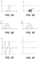
- a pulse P (characterized by its amplitude A distribution in function of time t, as shown in Fig. 3A ) has a plurality of component waves (shown in Fig. 3B ), each of them being characterized by their unique frequency f , their associated phase ⁇ (or relative phase) (shown Fig. 3C ), their magnitude M (shown in Fig. 3B ) and their mode.
- the pulse P becomes a dispersed wave DW (characterized by its amplitude A distribution in function of time t, as shown in Fig. 3D ) after propagation in the dispersive waveguide.
- the dispersed wave DW has the same component waves (shown in Fig. 3E ) characterized by the same frequencies f, the same magnitude M (shown in Fig. 3E ) but different associated phases ⁇ (shown in Fig. 3F ).
- the dispersive properties of the waveguide have introduced a phase shift between the component waves traveling through the dispersive waveguide. It is assumed that the waveguide is dispersive with no attenuation, as illustrated in Figs. 3B and 3E where a maximum magnitude M 1 is the same for in Figs. 3B and 3E . It is contemplated that some attenuation could be present.
- the inventors have realized that, when the dispersive properties of a waveguide are known, it is possible to program a source so as to generate a mechanical wave where the component waves of the mechanical wave have associated phases such that, once phase shift is introduced by the dispersive waveguide, the mechanical wave recombines at the other end of the waveguide into the desired mechanical wave.
- the wave generator of the present invention works according to this principle, by exploiting the dispersive properties of a waveguide to generate desired mechanical waves. Since the emitted mechanical waves are chosen by the user, in some cases, the wave generator can also be used as a ⁇ passive amplifier' to generate high amplitude acoustic pulses.
- the dispersive properties of the waveguide are predetermined. Knowing the dispersive properties consists in knowing the relationships between component waves and propagation velocities in the waveguide. A unique calibration step is sufficient to determine the dispersive properties. The calibration step can be done experimentally or analytically. In one example, the finite element method is used to determine the dispersion relationships. In another example, a hydrophone can be used to experimentally determine the dispersive properties.
- Initial calibration of the wave generator is done independently of an emitting source present in the medium. Montaldo et al., however, rely on an emitting source to calibrate initially their device. Further, the wave generator of the present invention uses the same calibration whatever the focal point is, whereas Montaldo et al. require a moving emitting source to calibrate different focal points. In addition, the present device can generate selected desired mechanical output waves that are designed according to the application the user intends to use the mechanical waves for, contrary to Montaldo et al. which device only generates mechanical output waves according the emitting source.
- the present invention uses a source (e. g. a single transducer) covering totally or partially an end of the waveguide, the mechanical waves generated can be one dimensional.
- the device of Montaldo et al. has instead a plurality of bi-directional transducers covering only partially the end of the reverberative cavity RC (as can be seen in Fig. 1 ) and this arrangement generates multi-dimensional waves.
- a one-dimensional source e. g. single transducer
- a tridimensional source e. g. plurality of transducers
- Puckett et al. in 'A time-reversal mirror in a solid circular waveguide using a single, time-reversal element', ARLO 4(2), April 2003 cleans the echoes present in a buffer rod placed between a target medium and a transducer by using the temporal reverse mirror method in order to cancel the undesired effects of dispersion.
- it is possible to eliminate the phase difference of a signal caused by dispersion with only one transducer covering a whole end of the buffer rod it is as much possible to efficiently exploit that dispersion in order to increase tenfold a one-dimensional source power.
- the wave generator can use a one-dimensional source, the wave generator can generate planar waves, which can propagate at relatively long distances away from the emitting end of the waveguide.
- the device of Montaldo et al. generates pulses focused at locations relatively close to the emitting end of the waveguide.
- the present wave generator can generate planar waves which excite a single mode. In some cases, the wave generator can excite solely the fundamental (first) mode of the waveguide. Although the present wave generator may be capable of exciting multiple modes, in one aspect the present wave generator does not require to excite more than one mode.
- the present invention provides a wave generator configured to emit a desired mechanical output wave into a medium
- the wave generator comprising: a wave emitter including: an elongated dispersive waveguide having a first end and a second end, when in operation the second end being at least partially in contact with the medium, dispersive properties of the elongated dispersive waveguide being dependent on a geometry and a composition thereof; and a source operatively connected to the first end of the dispersive waveguide covering at least partially a surface area of the first end, the source being configured to generate a mechanical input wave in the dispersive waveguide based on electrical signals input to the source; a signal generator in operative connection with the source, the signal generator being configured to create the electrical signals convertible by the source into the mechanical input wave in the dispersive waveguide; and a computer in operative connection with the signal generator, the computer having a processor and a machine-readable storage medium, the machine-readable storage medium containing instructions that when
- a method of emitting a desired mechanical output wave into a medium comprises emitting a desired mechanical output wave into a medium, the method comprising: providing an elongated dispersive waveguide having a first end and a second end, the second end being at least partially in contact with the medium dispersive properties of the elongated dispersive waveguide being dependent on a geometry and a composition thereof; determining the desired mechanical output wave; determining a mechanical input wave, the mechanical input wave having at least two component waves, each of at least two of the component waves having a unique predetermined propagation velocity through the dispersive waveguide, the mechanical input wave when inputted at the first end of the dispersive waveguide and once having propagated through the dispersive waveguide combining at least partially at the second end of the dispersive waveguide to form the desired mechanical output wave; generating by a source operatively connected to the first end of the dispersive waveguide the mechanical input wave at the first end of the dispersive waveguide; allowing the mechanical input
- wave includes all mechanical waves, i.e ., waves that propagate through a medium due to restoring forces they produce upon deformation of the medium.
- component waves refers to functions of space and time on which a mechanical wave can be decomposed.
- medium refers to any substance (e.g. gas, liquid, solid, gel, non-biological or biological material) that allows for the propagation of a mechanical wave through it.
- waveguide refers to a structure that conveys mechanical waves between its endpoints.
- shockwave refers to a region of abrupt change of pressure that moves a wave front at a relatively rapid velocity though a medium.
- acoustic refers to mechanical waves in gases, liquids, and solids at frequencies in the range of the sound, ultrasound and infrasound.
- disersion refers to a physical property of a waveguide by which component waves have different propagation velocities through that waveguide.
- source refers to any element capable of generating a generally planar longitudinal mechanical wave.
- Embodiments of the present invention each have at least one of the above-mentioned objects and/or aspects, but do not necessarily have all of them. It should be understood that some aspects of the present invention that have resulted from attempting to attain the above-mentioned objects may not satisfy these objects and/or may satisfy other objects not specifically recited herein.
- the wave emitter 10 has a waveguide 14 and a single transducer 12 disposed at a first end 15 of the waveguide 14. A second end 16 of the waveguide 14 is free. When in operation, the second 16 is put into contact with a medium 104 in which the wave emitter 10 emits mechanical waves.
- the medium 104 and a method for generating mechanical waves will be described below.
- the transducer 12 is fixedly disposed to the first end 15 by two screws (not shown) which exert pressure to retain the transducer 12 on the waveguide 14. It is contemplated that other ways to affix the transducer 12 to the waveguide 14 could be used. For example, the transducer 12 could be glued to the first end 15 of the waveguide. It is also contemplated that a gel (similar to the ones used in ultrasound imaging) could be disposed between the transducer 12 and the waveguide 14 to enhance energy transmission between the transducer 12 and the waveguide 14.
- the single transducer 12 is one example of source that could be used to generate mechanical waves into the waveguide 14.
- the waveguide 14 is an elongated rod of circular cross-section. It is contemplated that a waveguide 14 could have a cross-section different from circular. As shown in Fig. 5 , the waveguide 14 could be embodied as a waveguide 14a having a C-shape, and as shown in Fig. 6 , the waveguide 14 could also be embodied as a waveguide 14b being hollow and having a hole 8 along its length. It is also contemplated that the waveguide 14 could be a combination of the waveguides 14a and 14b, and could have a C-shape and one or more hole 8 with same or different shape and sizes. It is also contemplated that the waveguide 14 could have yet different shapes of cross-section.
- the waveguide 14 has a constant cross-section. It is contemplated that the waveguide 14 could not have a constant cross-section. For example, the waveguide 14 could have one end squared and another end circular and could transition smoothly between the two along its length. In another example, the waveguide is tapered.
- the waveguide 14 has an aspect ratio of 40. It is contemplated that the aspect ratio of the waveguide 14 could range between 10 and 1000. A length of the waveguide 14 is 1000 mm, and a cross-section area is 25 mm (area: 490 mm 2 ). The length of the waveguide 14 is preferably chosen, on one end to accommodate the fact that the longer the waveguide 14, the more dispersed a mechanical wave will be (and therefore the higher the gain) and on the other end, to accommodate the fact that the longer the waveguide 14, the more attenuated the mechanical wave will be after propagation through the waveguide 14. It is contemplated that the waveguide 14 could have other dimensions. For example, the length of the waveguide 14 could be between 200 mm and 1500 mm, and the diameter could be between 1 mm and 50 mm.
- the waveguide 14 is straight and inflexible. It is contemplated that the waveguide 14 could have some curvature. For example, a radius of curvature of the waveguide 14 could be one order of magnitude greater than a wavelength of a signal propagating through waveguide 14. As shown in Fig. 7 , the waveguide 14 could be embodied as a waveguide 14C that is flexible. The flexible waveguide 14C could have a size and mechanical compliance adapted to allow insertion of the waveguide 14C in place where access is restricted.
- the waveguide 14 is made of aluminum 6061-T6. It is contemplated that the waveguide 14 could be made of a different type of aluminum or a different material. It is also contemplated that the waveguide 14 could be made of an alloy of materials. For example the waveguide 14 could be made of aluminum, magnesium, stainless steel, titanium, etc. It is also contemplated that the waveguide 14 could be formed of two or more adjacently arranged waveguides. For example the waveguide 14 could be made of two concentrically arranged waveguides, each waveguide being made of a different material. The waveguide 14 is dispersive within a bandwidth of the transducer 12. The waveguide 14 also has a low attenuation coefficient around the central frequency of the transducer 12 for maximizing amplification gain.
- the transducer 12 is a single gas matrix piezoelectric of The Ultran Group model GWC-D28-10.
- the transducer 12 has a diameter of 25 mm and is sized to cover an entirety of the first end 15 of the waveguide 14. It is contemplated that the transducer 12 could be bigger or smaller than the first end 15.
- a planar wave can be generated.
- the transducer 12 is smaller than the cross-section of the waveguide 14 multiple reflections at walls of the waveguide 14 may deform the planar wave as it travels the waveguide 14.
- the planar waves are generally unfocused and excite one or more longitudinal modes of the waveguide 14. It is contemplated that the mechanical waves could not be planar, could not be unfocused, and could excite modes other than longitudinal modes.
- the transducer 12 is disposed at the first end 15 perpendicularly to a longitudinal direction of the waveguide 14. It is contemplated that the transducer 12 could be positioned at the first end 15 not perpendicularly to the longitudinal direction of the waveguide 14. It is contemplated that some reverberations could occur when the transducer 12 is not disposed perpendicularly to the longitudinal direction of the waveguide 14.
- the transducer 12 has a central frequency of 600 kHz. It is contemplated that the transducer 12 could have a central frequency different from 600 kHz.
- the transducer's 12 central frequency is preferably chosen in accordance with the dispersive properties of the waveguide 14. In the present case, a central frequency of 600 kHz is desired because the waveguide 14 is made of aluminum and is dispersive within a range around 600 kHz for the dimensions of the waveguide 14 recited above.
- a bandwidth of the transducer 12 is from 300 kHz to 900 KHz. It is contemplated that the transducer 12 could have a different bandwidth.
- the wave emitter 20 is similar to the wave emitter 10 but features a bi-directional transducer 22 in place of the unidirectional transducer 12. Elements of the wave emitter 20 common to the wave emitter 10 will have same reference numerals, and will not be described in detail herein again.
- the bi-directional transducer 22 can convert electric signals into mechanical waves and reversely, mechanical waves into electrical signals.
- the bi-directional transducer 22 enables the wave emitter 20 to detect mechanical waves in a medium 104 (shown in Fig. 11 ) in addition to emitting mechanical waves in the medium 104.
- a transducer assembly could replace the bi-directional transducer 22.
- the transducer assembly could be formed by the association of two transducers, the assembly covering the first end 15 of the waveguide 14.
- the two transducers could be disposed adjacent to each other or concentrically arranged. One of the two transducers could be used to emit mechanical waves, and the other to receive mechanical waves.
- An acoustic impedance coupler 18 can be coupled to any of the wave emitters 10 and 20 for increasing energy transmission of the mechanical wave between the second end 16 of the waveguide 14, and the medium 104.
- the acoustic impedance coupler 18 includes a layer of glass and a layer of epoxy between the glass and the second end 16 of the waveguide 14. The epoxy is used to glue the glass to the waveguide 14.
- Each of the layers of epoxy and glass is disk shaped to match the circular cross-section of the waveguide 14.
- the layer of epoxy has a thickness of 730 ⁇ m, and the layer of glass has a thickness of 300 ⁇ m.
- the acoustic impedance coupler 18 has an acoustic impedance intermediate to an acoustic impedance of the waveguide 14 and to an acoustic impedance of the medium 104. It is contemplated that the acoustic impedance coupler 18 could be embodied as a structure having different shape or material, or be even a gel or a softer material. It is also contemplated that the acoustic impedance coupler 18 could include a plurality of layers of glass and epoxy.
- An acoustic lens 23 (shown in Fig. 10 ) can be disposed at the second end 16 of the waveguide 14 of any of the wave emitters 10 and 20, to geometrically focus the mechanical waves emitted into the medium 104. It is also contemplated that the wave emitters 10 and 20 could have the acoustic lens 23 and the acoustic impedance coupler 18 disposed is series at the second end 16 of the waveguide 14. It is also contemplated that the acoustic lens 23 could not be used for focusing the mechanical waves emitted into the medium 104. For example, the wave emitters 10 and 20 could exploit diffraction effects at the second end 16 of the waveguide 14 to focus energy at a predetermined spatial location within the medium 104. Diffraction patterns are dependent on the shape and size of the second end as well as on a wavelength of the desired output wave. In other example, the second end 16 of the waveguide 14 could be shaped so as to geometrically focus the mechanical waves.
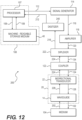
- the wave generator 100 is a system powering the wave emitter 10 and used to program the wave emitter 10 to generate desired mechanical waves.
- the wave emitter 10 is powered by a signal generator 114, which is programmable by a computer 106.
- the signal generator 114 is a National Instruments, PXI 5412 (14-Bit 100 MS/s).
- the computer 106 is a general purpose computer well known in the art. It is contemplated that the computer 106 could be another type of computing interface. It is contemplated that the signal generator 114 could be different.
- the computer 106 has a processor 107 in communication (data 108) with a machine-readable storage medium 110.
- the machine-readable storage medium 110 is used to store the data 108, which are digitized input signals corresponding to mechanical input waves 128.
- the computer 106 constitutes an interface used by a user to program an input signal 112 that will lead to the generation of one or more mechanical input waves 128.
- the signal generator 114 transforms the input signal 112 into a low voltage signal 116.
- the low voltage signal 116 is transformed into a higher voltage signal 120 by an amplifier 118.
- the amplifier 118 is a RITEC, GA-2500A (400 Watts). It is contemplated that the amplifier 118 could be different.
- the higher voltage signal 120 goes through a coupler 122 which optimizes power transfer between the amplifier 118 and the wave emitter 10 by coupling electric impedances of the amplifier 118 and the wave emitter 10. It is contemplated that the amplifier 118 could be omitted. After passage through the coupler 122, the higher voltage signal 120 becomes input voltage signal 124 to the wave emitter 10. It is contemplated that the coupler 122 could be omitted.
- the transducer 12 converts the input voltage signal 124 into the mechanical input wave 128, and the waveguide 14 propagates the mechanical input wave 128 towards the second end 16 of the waveguide 14 which is being put in contact with the medium 104 for generating mechanical waves 102 in the medium 104.
- the medium 104 is degassed tap water at room temperature. It is contemplated that the medium 104 could be different.
- the waveguide 14 being dispersive, the mechanical input wave 128 is distorted into a mechanical output wave 102 by the time the mechanical input wave 128 has reached the second end 16. Some component waves of the mechanical input wave 128 travel faster than others and can reach the second end 16 at the same time as the slower component waves. When the slower and faster components waves reach simultaneously the second end 16 an interaction occurs to form the mechanical output wave 102.
- the mechanical output wave 102 is a recombination of the mechanical input wave 128.
- the mechanical output wave 102 is emitted into the medium 104.
- the user starts with determining the desired mechanical output wave 102 that he/she wishes to emit in the medium 104.
- the user uses the computer 106 to determine the input signal 112 input to the signal generator 114 that ultimately will lead to the mechanical output wave 102 after conversion by the transducer 12 and propagation through the dispersive waveguide 14.
- a method for generating the mechanical output waves 102 will be described below.
- the input signal 112 is calculated taking into consideration the dispersive properties of the waveguide 14 and in some cases taking into consideration the physical properties of the medium 104.
- the dispersive properties of the waveguide 14 and the physical properties of the medium 104 are determined in a prior calibration step typically done only once.
- the waveguide 14 is calibrated using the impulse response method. It is contemplated that other methods well known in the art could be used to calibrate the waveguide 14. For example, time reversal mirror, inverse filter, or analytical calculation of dispersion curves could be used.
- a known pulse is sent by the transducer 12 into the waveguide 14, and after traveling through the waveguide 14 and being deformed due to the dispersive properties of the waveguide 14, the pulse propagates in the medium 104 until reaching a hydrophone (not shown) priory placed in front of the waveguide 14.
- An advantage of the impulse response calibration method is that it allows to take into consideration the characteristics of the medium 104 itself. It is possible that the choice of medium 104 influences a shape of the mechanical output waves 102, after having been generated at the second end 16, when the mechanical output waves 102 enter the medium 104. Therefore, it is preferable that the calibration takes into consideration the medium 104. It is contemplated that the medium 104 could be calibration in a separate calibration step.
- the hydrophone is a Müller-Platte Needleprobe 100-100-1 with a sensitive diameter inferior to 0.5 mm. It is contemplated that the hydrophone could be different.
- the hydrophone records the emitted wave which is used along with the impulse to characterize a frequency response function of the wave emitter 10.
- the frequency response function is a key of the system (wave emitter 10) which once known allows to determine how any wave will be modified into, after propagation in the dispersive waveguide 14. It is contemplated that if the transducer 12 were bi-directional, it could be possible to use, instead of the hydrophone, a reflection of the impulse itself at the second end 16 of the waveguide 14 in order to determine the frequency response function of the wave emitter 10.
- the wave generator 200 is a system powering the wave emitter 20 used to generate the desired mechanical output waves 102 and further to record information coming from the medium 104 for the purpose of, for example, locating a non-homogeneity in the medium 104.
- the wave generator 200 is similar to the wave generator 100, but features a diplexer 222 and a digitizer 240. Elements of the wave generator 200 common to the wave generator 100 will have same reference numerals, and will not be described herein again.
- the diplexer 222 is located between the amplifier 118 and the coupler 122.
- the diplexer 222 acts as a switch to separate electric signals 124 incoming and outgoing the bi-directional transducer 22.
- the diplexer 222 separates signals 234 incoming from the medium 104 through the waveguide 14 from signals 134 incoming from the signal generator 114.
- the diplexer 222 is only one example of a switch.
- the digitizer 240 transforms a signal 216 outgoing from the diplexer 222 into a signal 212 readable by the computer 106.
- the bi-directional transducer 22 converts the voltage signal 124 into the corresponding mechanical input wave 128, and reversely converts a mechanical wave 228 coming from the waveguide 14 (reverse direction mechanical wave) into a corresponding electric signal 224.
- Emission of mechanical waves by the wave generator 200 is similar to the one described below for the wave generator 100, except that the higher voltage signal 120 goes through the diplexer 222 and the coupler 122 before entering the wave emitter 20 without being noticeably deformed.
- Reception of mechanical waves by the wave generator 200 starts with the waveguide 14 receiving a mechanical wave 202 (e.g. perturbation) from the medium 104 at the second end 16.
- the mechanical wave 202 could be emitted from a source in the medium 104 or reflected by a non-homogeneity in the medium 104.
- the mechanical wave 202 propagates through the waveguide 14 toward the bi-directional transducer 22.
- the mechanical wave 202 reaches the bi-directional transducer 22
- the mechanical wave 202 has been transformed into the mechanical wave 228 which is a dispersed version of the mechanical wave 202.
- the bi-directional transducer 22 converts the mechanical wave 228 into a corresponding electric signal 224.
- the electric signal 224 goes through the coupler 122, becomes signal 234, goes through the diplexer 222 becomes the signal 216, before reaching the digitizer 240, and being transformed into the signal 212 readable by the computer 106.
- the wave emitter 20 can be used as a location device for a non-homogeneity.
- the calibration of the wave emitter 20 can be done in a unique calibration step, analytically or experimentally.
- the calibration of the wave emitter 20 is similar to the calibration for the wave emitter 10 described above.
- a method for locating a non-homogeneity in the medium 104 starts with the wave emitter 200 emitting a pulse. Then, the pulse is reflected by the non-homogeneity and reaches back the wave emitter 20 (with some distortion due to propagation in the medium 104). Dispersion in the waveguide 14 is taken into consideration by the prior calibration of the wave emitter 20.
- the reflected mechanical wave from the non-homogeneity is compared with the original pulse sent toward the non-homogeneity to determine a distance between the second end 16 of the waveguide 14 and the non-homogeneity. Comparison can be performed by the computer 106. It is also possible to exploit the waves reflected by the non-homogeneity to characterize heterogeneities in the medium 104.
- a method 300 for generating a desired mechanical wave by exploiting waveguide dispersion of the wave emitter 10 in the wave generator 100 will now be described.
- the method 300 will be described assuming the wave emitter 10 has been priory calibrated and the dispersive properties of the waveguide 14 (and optionally the physical properties of the medium 104) are known, as described above. It is contemplated that the method 300 could be used for generating a desired mechanical wave by exploiting waveguide dispersion of the wave emitter 20 in the wave generator 200.
- the method 300 starts at step 302, with the user determining the desired mechanical output wave 102.
- the desired mechanical output wave 102 has at least two component waves having relative phases between them.
- Each component wave has (among other characteristics) an associated frequency and an associated mode within the predetermined range of frequencies and modes for which the waveguide 14 is dispersive.
- the input signal 112 is calculated by the computer 106.
- the input signal 112 corresponds to the mechanical input wave 128 produced by the transducer 12, which once distorted by the dispersive waveguide 14 will recombine into the desired mechanical output wave 102.
- the input signal 112 is calculated taking into account the dispersive relations of the waveguide 14, so as to compensate at the end 16 of the waveguide 14 for the relative phase shifts introduced by the waveguide 14 as the components waves of the mechanical input wave 128 travel through it.
- the method 300 can go either through step 305, or directly to step 306.
- the input signal 112 is amplified.
- One way to amplify the input signal 112 is to saturate it before amplifying it. To do so, a magnitude of the input signal 112 for the different frequencies composing it, is fixed to a limit value, and consequently amplified. Saturating and amplifying the input signal 112 allows to amplify without affecting relative phases. It is contemplated that one could amplify and then saturate the input signal 112. It is contemplated that the saturation and amplification could be done differently. An example of amplification by saturation is given below.
- the input signal 112 is transformed by the transducer 12 into the mechanical input wave 128.
- the mechanical input wave 128 travels through the waveguide 14 and gets distorted due to the dispersive properties of the waveguide 14.
- a step 310 the desired mechanical output wave 102 is generated from a recombination of the mechanical input wave 128 at the second end 16. Once the desired mechanical output wave 102 is generated, it is emitted into the medium 104 at step 310. If at step 312, the wave emitter 10 is coupled to the acoustic impedance coupler 18, the desired mechanical output wave 102 propagates through the acoustic impedance coupler 18 before reaching the medium 104. If at step 314 the wave emitter 10 is coupled to the acoustic lens 23, the desired mechanical output wave 102 propagates through the acoustics lens 23 before reaching the medium 104 at step 314. The wave emitter 10 could also be coupled to the acoustic lens 23 and the acoustic impedance coupler 18.
- Figs. 14 to 17 an example of mechanical input wave 128 and a resulting desired mechanical output wave 102 will be described.
- the wave emitter 10 is connected to the impedance acoustic coupler 18 but has no acoustic lens 23 attached to it.
- the medium 104 is degassed tap water at room temperature.
- the wave emitter 10 is positioned so as to have the second end 16 in contact with the medium 104.
- the user desires to emit a pulse of a normalized amplitude of 3 and a desired time signature of 1.67 ⁇ s. It is contemplated that the experiment could be performed for generating a pulse other than the one above.
- the experiment could be performed for generating mechanical waves other than a pulse.
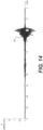
- the user uses the computer 106 to determine a mechanical input wave 400 that needs to be generated by the transducer 12 in order to generate at the second end 16 of the waveguide 14, the desired pulse.
- Fig. 14 shows the mechanical input wave 400 as generated by the transducer 12.
- the wave 400 is characterized by a time signature of 0.2 ms and an amplitude of 1 ( Fig. 14 showing the amplitude normalized).
- a pulse 410 characterized by a time signature of approximately 1.67 ⁇ s and an amplitude of 3 ( Fig. 15 showing the amplitude normalized) is recorded at the second end 16 of the waveguide 14.
- the wave generator 10 has passively compressed in time and has amplified the wave 400 to form the pulse 410.
- the gain is 3 and the temporal compression is of a factor of 120.
- the user can also saturate the signal leading to the generation of the mechanical input wave 400, so as to amplify even further the amplitude of the desired pulse 410.
- Fig. 16 when recorded at the second end 16 of the waveguide 14 is a pulse 420 having the same time signature as the pulse 410, but having an amplitude of 8 ( Fig. 16 showing the amplitude normalized). Saturation did not affect the time signature, and has increased the amplitude by about 2.7 times compared to the same experiment without saturation.
- the pulse 410 and 420 are emitted in the medium 104, non-linear effects of the medium 104 distort the pulses 401, 402 as they travel through it.
- the pulse 410 has becomes a shockwave 430.
- the shockwave 430 is characterized by a time signature of less than 1 ⁇ s and an amplitude of 100 bars. This amplitude of the shockwave 430 is 20 times more than a wave that would be created by the same transducer 12 (without waveguide 14), driven by the same electrical power and emitting in the same medium 104 (water).
Landscapes
- Health & Medical Sciences (AREA)
- Engineering & Computer Science (AREA)
- Life Sciences & Earth Sciences (AREA)
- General Health & Medical Sciences (AREA)
- Physics & Mathematics (AREA)
- Acoustics & Sound (AREA)
- Multimedia (AREA)
- Surgery (AREA)
- Veterinary Medicine (AREA)
- Public Health (AREA)
- Animal Behavior & Ethology (AREA)
- Heart & Thoracic Surgery (AREA)
- Biomedical Technology (AREA)
- Molecular Biology (AREA)
- Medical Informatics (AREA)
- Mechanical Engineering (AREA)
- Orthopedic Medicine & Surgery (AREA)
- Vascular Medicine (AREA)
- Nuclear Medicine, Radiotherapy & Molecular Imaging (AREA)
- Audiology, Speech & Language Pathology (AREA)
- Rehabilitation Therapy (AREA)
- Epidemiology (AREA)
- Pain & Pain Management (AREA)
- Physical Education & Sports Medicine (AREA)
- Surgical Instruments (AREA)
- Transducers For Ultrasonic Waves (AREA)
- Apparatuses For Generation Of Mechanical Vibrations (AREA)
- Investigating Or Analyzing Materials By The Use Of Ultrasonic Waves (AREA)
Claims (15)
- Générateur d'onde (100, 200) configuré pour émettre une onde de sortie mécanique souhaitée dans un milieu, le générateur d'onde comprenant :
un émetteur d'onde (10, 20) comportant :un guide d'ondes dispersif allongé (14) présentant une première extrémité et une deuxième extrémité, lors du fonctionnement la deuxième extrémité (16) étant au moins en partie en contact avec le milieu (104),une source (12) connectée de manière fonctionnelle à la première extrémité (15) du guide d'ondes dispersif couvrant au moins en partie une superficie de la première extrémité, la source étant configurée pour générer une onde d'entrée mécanique (128) dans le guide d'ondes dispersif sur la base de signaux électriques entrés dans la source ;un générateur de signal (114) en connexion fonctionnelle avec la source, le générateur de signal étant configuré pour créer les signaux électriques convertibles par la source en l'onde d'entrée mécanique dans le guide d'ondes dispersif ; etun ordinateur (106) en connexion fonctionnelle avec le générateur de signal, l'ordinateur présentant un processeur et un support de stockage lisible par machine (110), le support de stockage lisible par machine contenant des instructions qui lorsqu'elles sont exécutées par le processeur amènent le générateur de signal à créer des signaux électriques convertibles par la source en l'onde d'entrée mécanique,l'onde d'entrée mécanique présentant au moins deux ondes composantes, chacune des au moins deux des ondes composantes présentant une vitesse de propagation prédéterminée unique à travers le guide d'ondes dispersif, les au moins deux ondes composantes présentant des vitesses de propagation prédéterminées différentes à travers le guide d'ondes dispersif,les instructions d'ordinateur étant configurées pour interpréter l'onde d'entrée mécanique (i) indépendamment de données liées à une onde mécanique reçue d'une source dans le milieu et (ii) en prenant en compte les vitesses de propagation prédéterminées différentes des au moins deux ondes composantes de sorte que les au moins deux ondes composantes se combinent au moins en partie les unes avec les autres au niveau de la deuxième extrémité du guide d'ondes dispersif pour former l'onde de sortie mécanique (102) souhaitée émise dans le milieu,caractérisé en ce que :les propriétés dispersives du guide d'ondes dispersif allongé dépendent d'une géométrie et d'une composition de celui-ci ;les instructions d'ordinateur sont en outre configurées pour interpréter les au moins deux ondes composantes présentant chacune une fréquence associée et excitant chacune un mode associé du guide d'ondes, etsoit les au moins deux ondes composantes présentent une même fréquence associée et excitent chacune des modes associés différents du guide d'ondes, soitles au moins deux ondes composantes présentent chacune des fréquences associées différentes et excitent un même mode associé du guide d'ondes, soit les au moins deux ondes composantes présentent chacune des fréquences associées différentes et excitent chacune des modes associés différents du guide d'ondes. - Générateur d'onde selon la revendication 1, dans lequel l'onde d'entrée mécanique présente une première durée dans le temps, l'onde de sortie mécanique souhaitée présente une deuxième durée dans le temps, et la première durée dans le temps est plus longue que la deuxième durée dans le temps.
- Générateur d'onde selon l'une quelconque des revendications 1 et 2, dans lequel l'onde d'entrée mécanique présente une première amplitude, l'onde de sortie mécanique souhaitée présente une deuxième amplitude, et la deuxième amplitude est plus grande que la première amplitude.
- Générateur d'onde selon l'une quelconque des revendications 1 à 3, dans lequel le même mode associé est un monomode du guide d'ondes.
- Générateur d'onde selon la revendication 4, dans lequel le monomode est un mode longitudinal fondamental du guide d'ondes.
- Générateur d'onde selon l'une quelconque des revendications 1 à 5, comprenant en outre une ou plusieurs des caractéristiques suivantes :- la source est un transducteur ;- la source présente une largeur de bande de fréquence, les au moins deux ondes composantes présentent chacune une fréquence associée, et les fréquences associées des au moins deux ondes composantes sont à l'intérieur de la largeur de bande de fréquence de la source ;- la source couvre au moins une totalité de la superficie de la première extrémité du guide d'ondes dispersif ;- le guide d'ondes dispersif présente une section transversale constante ;- au moins l'un d'un coupleur d'impédance acoustique et d'une lentille acoustique étant connecté de manière fonctionnelle à la deuxième extrémité du guide d'ondes dispersif, le coupleur d'impédance acoustique comporte au moins une couche présentant une impédance acoustique intermédiaire par rapport à une impédance acoustique du guide d'ondes dispersif et à une impédance acoustique du milieu, l'au moins une couche est agencée en fonction de son impédance acoustique de manière à maximiser la transmission d'énergie de l'onde de sortie mécanique souhaitée entre la deuxième extrémité du guide d'ondes dispersif et le milieu ;- à l'intérieur d'une largeur de bande de fréquence de la source, un coefficient d'atténuation du guide d'ondes dispersif est tel que l'émetteur d'onde présente un gain positif ;- le guide d'ondes dispersif est un choisi dans le groupe constitué par un métal et une céramique ;- un rapport d'aspect du guide d'ondes dispersif est au moins 10 ;- l'onde de sortie mécanique souhaitée est généralement plane ;- l'onde de sortie mécanique souhaitée est non focalisée ou focalisée ;- le guide d'ondes dispersif est courbé le long de sa longueur au moins en partie entre la première extrémité et la deuxième extrémité ;- le guide d'ondes dispersif présente un rayon de courbure au moins d'un ordre de magnitude de longueurs d'onde des au moins deux ondes composantes ;- le guide d'ondes dispersif est flexible ; et- le générateur d'onde comprend en outre un amplificateur connecté de manière fonctionnelle au générateur de signal, l'amplificateur ayant pour fonction de modifier une amplitude d'au moins une partie des signaux électriques entrés dans la source.
- Générateur d'onde selon l'une quelconque des revendications 1 à 6,dans lequel la source est une source bidirectionnelle, et a en outre pour fonction de générer des signaux électriques de sortie à partir d'une onde mécanique en sens inverse, l'onde mécanique en sens inverse se propageant à travers le guide d'ondes dispersif à partir de la deuxième extrémité vers la première extrémité du guide d'ondes dispersif ; etle générateur d'onde comprenant en outre :un commutateur en connexion fonctionnelle avec la source bidirectionnelle, le commutateur ayant pour fonction de séparer les signaux électriques d'entrée destinés à être entrés dans la source bidirectionnelle des signaux électriques de sortie sortis de la source bidirectionnelle ; etun numériseur (240) en connexion fonctionnelle avec le commutateur et avec l'ordinateur, le numériseur ayant pour fonction de numériser les signaux électriques de sortie pour utilisation par l'ordinateur.
- Procédé d'émission d'une onde de sortie mécanique souhaitée dans un milieu, le procédé comprenant :la fourniture d'un guide d'ondes dispersif allongé (14) présentant une première extrémité (15) et une deuxième extrémité (16), la deuxième extrémité étant au moins en partie en contact avec le milieu (104),la détermination de l'onde de sortie mécanique (102) souhaitée ;la détermination d'une onde d'entrée mécanique (128), l'onde d'entrée mécanique présentant au moins deux ondes composantes, chacune d'au moins deux des ondes composantes présentant une vitesse de propagation prédéterminée unique à travers le guide d'ondes dispersif, l'onde d'entrée mécanique lorsqu'elle est entrée au niveau de la première extrémité du guide d'ondes dispersif et une fois s'étant propagée à travers le guide d'ondes dispersif se combinant au moins en partie au niveau de la deuxième extrémité du guide d'ondes dispersif pour former l'onde de sortie mécanique souhaitée ;la génération par une source connectée de manière fonctionnelle à la première extrémité du guide d'ondes dispersif de l'onde d'entrée mécanique au niveau de la première extrémité du guide d'ondes dispersif ;le fait de laisser l'onde d'entrée mécanique se propager à travers le guide d'ondes dispersif en direction de la deuxième extrémité ;la combinaison de l'onde d'entrée mécanique pour former l'onde de sortie mécanique souhaitée au niveau de la deuxième extrémité du guide d'ondes dispersif en raison des différences des vitesses de propagation prédéterminées des au moins deux ondes composantes ; etl'émission de l'onde de sortie mécanique souhaitée dans le milieu au niveau de la deuxième extrémité du guide d'ondes dispersif,les au moins deux ondes composantes présentant des vitesses de propagation prédéterminées différentes à travers le guide d'ondes dispersif,l'onde d'entrée mécanique étant interprétée (i) indépendamment de données liées à une onde mécanique reçue d'une source dans le milieu et (ii) en prenant en compte les vitesses de propagation prédéterminées différentes des au moins deux ondes composantes de sorte que les au moins deux ondes composantes se combinent au moins en partie les unes avec les autres au niveau de la deuxième extrémité du guide d'ondes dispersif pour former l'onde de sortie mécanique souhaitée émise dans le milieu,caractérisé en ce que :les propriétés dispersives du guide d'ondes dispersif allongé dépendent d'une géométrie et d'une composition de celui-ci ;les au moins deux ondes composantes présentent chacune une fréquence associée et excitent chacune un mode associé du guide d'ondes,soit les au moins deux ondes composantes présentent chacune des fréquences associées différentes et excitent un même mode associé, soitles au moins deux ondes composantes excitent chacune des modes associés différents et présentent une même fréquence associée, soitles au moins deux ondes composantes présentent chacune des fréquences associées différentes et excitent chacune des modes associés différents du guide d'ondes.
- Procédé selon la revendication 8, dans lequel la combinaison de l'onde d'entrée mécanique présentant une première durée dans le temps pour former l'onde de sortie mécanique souhaitée présentant une deuxième durée dans le temps comporte le raccourcissement de la première durée dans le temps en la deuxième durée dans le temps.
- Procédé selon l'une quelconque des revendications 8 et 9, dans lequel la combinaison de l'onde d'entrée mécanique pour former l'onde de sortie mécanique souhaitée comporte la combinaison de l'onde d'entrée mécanique présentant une première amplitude pour former l'onde de sortie mécanique souhaitée présentant une deuxième amplitude, la deuxième amplitude étant plus grande que la première amplitude.
- Procédé selon l'une quelconque des revendications 8 à 10, dans lequel le même mode associé est un monomode du guide d'ondes.
- Procédé selon la revendication 11, dans lequel le monomode est le monomode est un mode fondamental du guide d'ondes.
- Procédé selon l'une quelconque des revendications 8 à 12, comprenant en outre une ou plusieurs des caractéristiques suivantes :- la source est un transducteur ;- la source présente une largeur de bande de fréquence, les au moins deux ondes composantes présentent chacune une fréquence associée, et les fréquences associées des au moins deux ondes composantes sont à l'intérieur de la largeur de bande de fréquence de la source ;- la source couvre au moins une totalité de la superficie de la première extrémité du guide d'ondes dispersif ;- le guide d'ondes dispersif présente une section transversale constante ;- le procédé comprend en outre l'émission de l'onde de sortie mécanique souhaitée dans au moins l'un d'un coupleur d'impédance acoustique et d'une lentille acoustique avant l'émission de l'onde de sortie mécanique souhaitée dans le milieu, et le coupleur d'impédance acoustique comporte au moins une couche avant l'émission de l'onde de sortie mécanique souhaitée dans le milieu, l'au moins une couche présentant une impédance acoustique intermédiaire par rapport à une impédance acoustique du guide d'ondes dispersif et à une impédance acoustique du milieu, l'au moins une couche étant agencée en fonction de son impédance acoustique de manière à maximiser la transmission d'énergie de l'onde de sortie mécanique souhaitée entre la deuxième extrémité du guide d'ondes dispersif et le milieu ;- à l'intérieur d'une largeur de bande de fréquence de la source, un coefficient d'atténuation du guide d'ondes dispersif est tel que l'émetteur d'onde présente un gain positif ;- le guide d'ondes dispersif est un choisi dans le groupe constitué par un métal et une céramique ;- un rapport d'aspect du guide d'ondes dispersif est au moins 10 ;- l'émission de l'onde de sortie mécanique souhaitée dans le milieu comporte l'émission de l'onde de sortie mécanique souhaitée en tant qu'onde généralement plane ;- l'émission de l'onde de sortie mécanique souhaitée dans le milieu comporte l'émission de l'onde de sortie mécanique souhaitée non focalisée dans le milieu ;- l'émission de l'onde de sortie mécanique souhaitée dans le milieu comporte l'émission de l'onde de sortie mécanique souhaitée focalisée dans le milieu ;- le guide d'ondes dispersif est courbé le long de sa longueur au moins en partie entre la première extrémité et la deuxième extrémité ;- le guide d'ondes dispersif présente un rayon de courbure au moins d'un ordre de magnitude de longueurs d'onde des au moins deux ondes composantes ; et- le guide d'ondes dispersif est flexible.
- Procédé selon l'une quelconque des revendications 8 à 13, comprenant en outre :la détermination d'une amplitude de coupure ;la saturation du signal électrique d'entrée par rapport à l'amplitude de coupure pour qu'il devienne un signal saturé ; etl'amplification d'au moins une partie du signal saturé,avant l'entrée du signal électrique d'entrée dans la source.
- Procédé selon l'une quelconque des revendications 8 à 14, dans lequel la génération de l'onde d'entrée mécanique au niveau de la première extrémité du guide d'ondes dispersif comporte :la génération d'un signal électrique d'entrée correspondant à l'onde d'entrée mécanique ; etl'entrée du signal électrique d'entrée dans la source disposée au niveau de la première extrémité du guide d'ondes dispersif, la source transformant le signal d'entrée en l'onde d'entrée mécanique.
Applications Claiming Priority (2)
| Application Number | Priority Date | Filing Date | Title |
|---|---|---|---|
| US37751910P | 2010-08-27 | 2010-08-27 | |
| PCT/IB2011/002701 WO2012025833A2 (fr) | 2010-08-27 | 2011-08-29 | Générateur d'ondes mécaniques et procédé associé |
Publications (3)
| Publication Number | Publication Date |
|---|---|
| EP2608897A2 EP2608897A2 (fr) | 2013-07-03 |
| EP2608897C0 EP2608897C0 (fr) | 2023-08-02 |
| EP2608897B1 true EP2608897B1 (fr) | 2023-08-02 |
Family
ID=45723862
Family Applications (1)
| Application Number | Title | Priority Date | Filing Date |
|---|---|---|---|
| EP11819487.7A Active EP2608897B1 (fr) | 2010-08-27 | 2011-08-29 | Générateur d'ondes mécaniques et procédé associé |
Country Status (4)
| Country | Link |
|---|---|
| US (1) | US9833373B2 (fr) |
| EP (1) | EP2608897B1 (fr) |
| CA (1) | CA2809746C (fr) |
| WO (1) | WO2012025833A2 (fr) |
Families Citing this family (43)
| Publication number | Priority date | Publication date | Assignee | Title |
|---|---|---|---|---|
| US10702293B2 (en) | 2008-06-13 | 2020-07-07 | Shockwave Medical, Inc. | Two-stage method for treating calcified lesions within the wall of a blood vessel |
| ES2671898T3 (es) | 2008-06-13 | 2018-06-11 | Shockwave Medical, Inc. | Sistema de catéter con globo de ondas de choque |
| US9642673B2 (en) | 2012-06-27 | 2017-05-09 | Shockwave Medical, Inc. | Shock wave balloon catheter with multiple shock wave sources |
| WO2014025397A1 (fr) | 2012-08-06 | 2014-02-13 | Shockwave Medical, Inc. | Electrodes à profil bas pour cathéter à onde de choc d'angioplastie |
| CA2887832C (fr) * | 2013-08-16 | 2015-09-08 | Kevin Allan Dooley Inc. | Systemes et procedes de commande de pressions a infrasons |
| US10048151B2 (en) | 2013-08-16 | 2018-08-14 | Kevin Allan Dooley, Inc. | Systems and methods for control of motion sickness within a moving structure due to infrasound pressures |
| US9730715B2 (en) | 2014-05-08 | 2017-08-15 | Shockwave Medical, Inc. | Shock wave guide wire |
| KR20160089689A (ko) * | 2015-01-20 | 2016-07-28 | 삼성전자주식회사 | 초음파 프로브, 및 이를 포함하는 초음파 영상장치, 및 그 제어방법 |
| CA3218014A1 (fr) | 2015-04-24 | 2016-10-27 | Les Solutions Medicales Soundbite Inc. | Dispositif de connexion pour guides d'ondes mecaniques |
| US20160310354A1 (en) * | 2015-04-27 | 2016-10-27 | International Business Machines Corporation | Acoustic stimulation for the prevention and treatment of obesity |
| WO2017087195A1 (fr) | 2015-11-18 | 2017-05-26 | Shockwave Medical, Inc. | Électrodes d'onde de choc |
| CN109328115B (zh) | 2016-04-25 | 2021-11-12 | 莱斯桑百特医疗解决方案股份有限公司 | 其上设有标记件的机械波导 |
| US10226265B2 (en) | 2016-04-25 | 2019-03-12 | Shockwave Medical, Inc. | Shock wave device with polarity switching |
| CA3029129A1 (fr) * | 2016-06-30 | 2018-01-04 | Les Solutions Medicales Soundbite Inc. | Procede et systeme de traitement de lesions |
| RU2753466C2 (ru) * | 2016-10-26 | 2021-08-16 | Лес Солютионс Медикалес Соундбите Инк. | Катетерное устройство для подведения механических волн |
| US10357264B2 (en) | 2016-12-06 | 2019-07-23 | Shockwave Medical, Inc. | Shock wave balloon catheter with insertable electrodes |
| US11020135B1 (en) | 2017-04-25 | 2021-06-01 | Shockwave Medical, Inc. | Shock wave device for treating vascular plaques |
| US10966737B2 (en) | 2017-06-19 | 2021-04-06 | Shockwave Medical, Inc. | Device and method for generating forward directed shock waves |
| US10709462B2 (en) | 2017-11-17 | 2020-07-14 | Shockwave Medical, Inc. | Low profile electrodes for a shock wave catheter |
| US11103262B2 (en) | 2018-03-14 | 2021-08-31 | Boston Scientific Scimed, Inc. | Balloon-based intravascular ultrasound system for treatment of vascular lesions |
| US11819229B2 (en) | 2019-06-19 | 2023-11-21 | Boston Scientific Scimed, Inc. | Balloon surface photoacoustic pressure wave generation to disrupt vascular lesions |
| CN112367934A (zh) | 2018-06-21 | 2021-02-12 | 冲击波医疗公司 | 治疗躯体管腔中的闭塞物的系统 |
| US11622779B2 (en) | 2018-10-24 | 2023-04-11 | Boston Scientific Scimed, Inc. | Photoacoustic pressure wave generation for intravascular calcification disruption |
| US10825437B2 (en) | 2018-12-12 | 2020-11-03 | Pq Productions Llc | Stringed-instrument amplification |
| US11717139B2 (en) | 2019-06-19 | 2023-08-08 | Bolt Medical, Inc. | Plasma creation via nonaqueous optical breakdown of laser pulse energy for breakup of vascular calcium |
| US11660427B2 (en) | 2019-06-24 | 2023-05-30 | Boston Scientific Scimed, Inc. | Superheating system for inertial impulse generation to disrupt vascular lesions |
| US20200406010A1 (en) | 2019-06-26 | 2020-12-31 | Boston Scientific Scimed, Inc. | Side light direction plasma system to disrupt vascular lesions |
| JP7515576B2 (ja) | 2019-09-24 | 2024-07-12 | ショックウェーブ メディカル, インコーポレイテッド | 身体管腔内の血栓を治療するためのシステム |
| US11583339B2 (en) | 2019-10-31 | 2023-02-21 | Bolt Medical, Inc. | Asymmetrical balloon for intravascular lithotripsy device and method |
| USD882106S1 (en) * | 2019-11-21 | 2020-04-21 | Chongde Qiu | Sex toy |
| US11672599B2 (en) | 2020-03-09 | 2023-06-13 | Bolt Medical, Inc. | Acoustic performance monitoring system and method within intravascular lithotripsy device |
| US20210290286A1 (en) | 2020-03-18 | 2021-09-23 | Bolt Medical, Inc. | Optical analyzer assembly and method for intravascular lithotripsy device |
| US11707323B2 (en) | 2020-04-03 | 2023-07-25 | Bolt Medical, Inc. | Electrical analyzer assembly for intravascular lithotripsy device |
| US11992232B2 (en) | 2020-10-27 | 2024-05-28 | Shockwave Medical, Inc. | System for treating thrombus in body lumens |
| US12016610B2 (en) | 2020-12-11 | 2024-06-25 | Bolt Medical, Inc. | Catheter system for valvuloplasty procedure |
| US11672585B2 (en) | 2021-01-12 | 2023-06-13 | Bolt Medical, Inc. | Balloon assembly for valvuloplasty catheter system |
| US11648057B2 (en) | 2021-05-10 | 2023-05-16 | Bolt Medical, Inc. | Optical analyzer assembly with safety shutdown system for intravascular lithotripsy device |
| US11806075B2 (en) | 2021-06-07 | 2023-11-07 | Bolt Medical, Inc. | Active alignment system and method for laser optical coupling |
| US12089861B2 (en) | 2021-08-05 | 2024-09-17 | Nextern Innovation, Llc | Intravascular lithotripsy system and device |
| US12023098B2 (en) | 2021-10-05 | 2024-07-02 | Shockwave Medical, Inc. | Lesion crossing shock wave catheter |
| WO2023069902A1 (fr) | 2021-10-19 | 2023-04-27 | Shockwave Medical, Inc. | Cathéter de lithotripsie intravasculaire avec ondes de choc interférentes |
| US11839391B2 (en) | 2021-12-14 | 2023-12-12 | Bolt Medical, Inc. | Optical emitter housing assembly for intravascular lithotripsy device |
| US12035932B1 (en) | 2023-04-21 | 2024-07-16 | Shockwave Medical, Inc. | Intravascular lithotripsy catheter with slotted emitter bands |
Family Cites Families (40)
| Publication number | Priority date | Publication date | Assignee | Title |
|---|---|---|---|---|
| CH574734A5 (fr) | 1973-10-12 | 1976-04-30 | Dornier System Gmbh | |
| US4276491A (en) | 1979-10-02 | 1981-06-30 | Ausonics Pty. Limited | Focusing piezoelectric ultrasonic medical diagnostic system |
| DE3328051A1 (de) | 1983-08-03 | 1985-02-14 | Siemens AG, 1000 Berlin und 8000 München | Einrichtung zum beruehrungslosen zertruemmern von konkrementen |
| DE3543867C3 (de) | 1985-12-12 | 1994-10-06 | Wolf Gmbh Richard | Vorrichtung zur räumlichen Ortung und zur Zerstörung von Konkrementen in Körperhöhlen |
| US4907573A (en) * | 1987-03-21 | 1990-03-13 | Olympus Optical Co., Ltd. | Ultrasonic lithotresis apparatus |
| EP0316863B2 (fr) | 1987-11-16 | 2000-11-29 | Kabushiki Kaisha Toshiba | Appareillage de traitement par onde de choc |
| DE3803275A1 (de) | 1988-02-04 | 1989-08-17 | Dornier Medizintechnik | Piezoelektrische stosswellenquelle |
| US4957099A (en) | 1988-02-10 | 1990-09-18 | Siemens Aktiengesellschaft | Shock wave source for extracorporeal lithotripsy |
| EP0340470A1 (fr) | 1988-05-06 | 1989-11-08 | Satronic Ag | Procédé et circuit pour exciter un transducteur par ultrasons, et leur utilisation pour l'atomisation d'un liquide |
| EP0359863B1 (fr) | 1988-09-23 | 1994-05-04 | Siemens Aktiengesellschaft | Générateur haute tension et méthode de production d'une impulsion haute tension à forte intensité de courant pour commander un générateur d'ondes de choc |
| DE3907605C2 (de) | 1989-03-09 | 1996-04-04 | Dornier Medizintechnik | Stosswellenquelle |
| DE3932959C1 (fr) | 1989-10-03 | 1991-04-11 | Richard Wolf Gmbh, 7134 Knittlingen, De | |
| DE3932966C1 (fr) | 1989-10-03 | 1991-04-04 | Richard Wolf Gmbh, 7134 Knittlingen, De | |
| DE3932967A1 (de) | 1989-10-03 | 1991-04-11 | Wolf Gmbh Richard | Ultraschall-stosswellenwandler |
| DE4117638A1 (de) | 1990-05-30 | 1991-12-05 | Toshiba Kawasaki Kk | Stosswellengenerator mit einem piezoelektrischen element |
| US5064265A (en) | 1990-06-04 | 1991-11-12 | Hoechst Celanese Corp. | Optical parametric amplifier |
| EP0461287B1 (fr) | 1990-06-13 | 1994-05-04 | Siemens Aktiengesellschaft | Générateur d'ondes de choc entraîné électriquement |
| FR2664120B1 (fr) | 1990-06-27 | 1993-05-21 | Commissariat Energie Atomique | Systeme d'emission-reception d'ultrasons. |
| DE4130796A1 (de) | 1990-09-27 | 1992-04-02 | Siemens Ag | Elektrisch antreibbare stosswellenquelle |
| DE4132343C1 (fr) | 1991-09-27 | 1992-12-10 | Siemens Ag, 8000 Muenchen, De | |
| GB9126082D0 (en) * | 1991-12-06 | 1992-02-05 | Nat Res Dev | Acoustic non-destructive testing |
| US5370120A (en) | 1992-12-08 | 1994-12-06 | Siemens Aktiengesellschaft | Ultrasound imaging apparatus |
| US5509417A (en) | 1994-12-19 | 1996-04-23 | Hewlett Packard Company | Method and apparatus for phased array coupling ultrasonic energy into an acoustic waveguide wire |
| DE19539195A1 (de) | 1995-10-20 | 1997-04-24 | Vladimir Dr Abramov | Gerät zur Einkopplung von Ultraschall in ein flüssiges oder pastöses Medium |
| CA2202586C (fr) | 1996-04-15 | 2003-05-06 | Masashi Onishi | Fibre compensatrice de dispersion et systeme de transmission optique comprenant cette fibre |
| US20020040199A1 (en) | 1997-12-29 | 2002-04-04 | Klopotek Peter J. | Method and apparatus for therapeutic treatment of skin |
| JP4137211B2 (ja) | 1998-02-23 | 2008-08-20 | 富士通株式会社 | 分散補償ファイバ及びそれを用いた光増幅装置 |
| US6948843B2 (en) | 1998-10-28 | 2005-09-27 | Covaris, Inc. | Method and apparatus for acoustically controlling liquid solutions in microfluidic devices |
| US20020108631A1 (en) * | 1999-01-21 | 2002-08-15 | Madanshetty Sameer I. | Single-transducer ACIM method and apparatus |
| US6936009B2 (en) * | 2001-02-27 | 2005-08-30 | General Electric Company | Matching layer having gradient in impedance for ultrasound transducers |
| FR2830468B1 (fr) | 2001-10-04 | 2004-02-20 | Inst Nat Sante Rech Med | Dispositif et procede de production d'impulsions ultrasonores de forte pression |
| AU2002219490A1 (en) | 2002-01-08 | 2003-07-24 | Bio Scan Ltd. | Ultrasonic transducer probe |
| US20030199857A1 (en) | 2002-04-17 | 2003-10-23 | Dornier Medtech Systems Gmbh | Apparatus and method for manipulating acoustic pulses |
| US8376946B2 (en) | 2002-05-16 | 2013-02-19 | Barbara Ann Karamanos Cancer Institute | Method and apparatus for combined diagnostic and therapeutic ultrasound system incorporating noninvasive thermometry, ablation control and automation |
| EP1701659A4 (fr) | 2003-08-14 | 2010-04-07 | Univ Duke | Procede de lithotripsie par onde de choc amelioree a generateur combine d'onde de choc a reseau piezoelectrique annulaire et hydraulique |
| US20080146970A1 (en) | 2005-12-06 | 2008-06-19 | Julia Therapeutics, Llc | Gel dispensers for treatment of skin with acoustic energy |
| ITVR20060113A1 (it) | 2006-06-07 | 2008-01-07 | Giglio Antonio Del | Dispositivo per il trattamento del tessuto adiposo sottocutaneo mediante shockwaves non foicalizzate e contrapposte |
| US7724420B2 (en) | 2006-10-10 | 2010-05-25 | Raytheon Company | Frequency modulation structure and method utilizing frozen shockwave |
| FR2912817B1 (fr) | 2007-02-21 | 2009-05-22 | Super Sonic Imagine Sa | Procede d'optimisation de la focalisation d'ondes au travers d'un element introducteur d'aberations. |
| US8061014B2 (en) * | 2007-12-03 | 2011-11-22 | Covidien Ag | Method of assembling a cordless hand-held ultrasonic cautery cutting device |
-
2011
- 2011-08-29 US US13/819,575 patent/US9833373B2/en active Active
- 2011-08-29 EP EP11819487.7A patent/EP2608897B1/fr active Active
- 2011-08-29 CA CA2809746A patent/CA2809746C/fr active Active
- 2011-08-29 WO PCT/IB2011/002701 patent/WO2012025833A2/fr active Application Filing
Also Published As
| Publication number | Publication date |
|---|---|
| US9833373B2 (en) | 2017-12-05 |
| CA2809746A1 (fr) | 2012-03-01 |
| WO2012025833A2 (fr) | 2012-03-01 |
| US20130158453A1 (en) | 2013-06-20 |
| EP2608897C0 (fr) | 2023-08-02 |
| WO2012025833A3 (fr) | 2012-05-03 |
| CA2809746C (fr) | 2019-02-12 |
| EP2608897A2 (fr) | 2013-07-03 |
Similar Documents
| Publication | Publication Date | Title |
|---|---|---|
| EP2608897B1 (fr) | Générateur d'ondes mécaniques et procédé associé | |
| Gibbs et al. | Ultrasound physics and technology: how, why and when | |
| Azuma et al. | Dual-frequency ultrasound imaging and therapeutic bilaminar array using frequency selective isolation layer | |
| US4205686A (en) | Ultrasonic transducer and examination method | |
| Bercoff et al. | Sonic boom in soft materials: The elastic Cerenkov effect | |
| US4957099A (en) | Shock wave source for extracorporeal lithotripsy | |
| JPWO2005120360A1 (ja) | 静電容量型超音波プローブ装置 | |
| JPS59131335A (ja) | 超音波診断撮像装置 | |
| US5509417A (en) | Method and apparatus for phased array coupling ultrasonic energy into an acoustic waveguide wire | |
| US20050245824A1 (en) | High-intensity focused-ultrasound hydrophone | |
| US5458120A (en) | Ultrasonic transducer with magnetostrictive lens for dynamically focussing and steering a beam of ultrasound energy | |
| Montaldo et al. | Ultrasound shock wave generator with one-bit time reversal in a dispersive medium, application to lithotripsy | |
| Roux et al. | Experimental evidence in acoustics of the violation of time-reversal invariance induced by vorticity | |
| JP5179836B2 (ja) | 超音波探触子 | |
| IL173358A (en) | Imaging method using sound waves and a device | |
| Wevers et al. | Low-frequency ultrasonic piezoceramic sandwich transducer | |
| Arnal et al. | Tunable time-reversal cavity for high-pressure ultrasonic pulses generation: A tradeoff between transmission and time compression | |
| CN108889589A (zh) | 超声换能器及超声装置 | |
| Choi et al. | Two-dimensional virtual array for ultrasonic nondestructive evaluation using a time-reversal chaotic cavity | |
| Cathignol et al. | Electronic beam steering of shock waves | |
| Sutin et al. | Spatial and temporal concentrating of ultrasound energy in complex systems by single transmitter using time reversal principles | |
| JPH08206115A (ja) | 音波を音響導波管と結合する装置 | |
| Lindström et al. | Application of air-borne ultrasound to biomedical measurements | |
| Huang et al. | Improvements on focused tactile feedback using time reversal mirror | |
| Moriya et al. | Development of flexible acoustic transmission line for intravascular ultrasonography |
Legal Events
| Date | Code | Title | Description |
|---|---|---|---|
| PUAI | Public reference made under article 153(3) epc to a published international application that has entered the european phase |
Free format text: ORIGINAL CODE: 0009012 |
|
| 17P | Request for examination filed |
Effective date: 20130326 |
|
| AK | Designated contracting states |
Kind code of ref document: A2 Designated state(s): AL AT BE BG CH CY CZ DE DK EE ES FI FR GB GR HR HU IE IS IT LI LT LU LV MC MK MT NL NO PL PT RO RS SE SI SK SM TR |
|
| DAX | Request for extension of the european patent (deleted) | ||
| R17P | Request for examination filed (corrected) |
Effective date: 20130326 |
|
| R17P | Request for examination filed (corrected) |
Effective date: 20130326 |
|
| STAA | Information on the status of an ep patent application or granted ep patent |
Free format text: STATUS: EXAMINATION IS IN PROGRESS |
|
| 17Q | First examination report despatched |
Effective date: 20180605 |
|
| STAA | Information on the status of an ep patent application or granted ep patent |
Free format text: STATUS: EXAMINATION IS IN PROGRESS |
|
| STAA | Information on the status of an ep patent application or granted ep patent |
Free format text: STATUS: EXAMINATION IS IN PROGRESS |
|
| REG | Reference to a national code |
Ref country code: DE Ref legal event code: R079 Ref document number: 602011074131 Country of ref document: DE Free format text: PREVIOUS MAIN CLASS: B06B0001020000 Ipc: B06B0003000000 Ref country code: DE Ref legal event code: R079 Free format text: PREVIOUS MAIN CLASS: B06B0001020000 Ipc: B06B0003000000 |
|
| GRAP | Despatch of communication of intention to grant a patent |
Free format text: ORIGINAL CODE: EPIDOSNIGR1 |
|
| STAA | Information on the status of an ep patent application or granted ep patent |
Free format text: STATUS: GRANT OF PATENT IS INTENDED |
|
| RIC1 | Information provided on ipc code assigned before grant |
Ipc: A61B 17/225 20060101ALI20230116BHEP Ipc: G10K 15/04 20060101ALI20230116BHEP Ipc: G10K 15/02 20060101ALI20230116BHEP Ipc: B06B 3/00 20060101AFI20230116BHEP |
|
| INTG | Intention to grant announced |
Effective date: 20230221 |
|
| RAP3 | Party data changed (applicant data changed or rights of an application transferred) |
Owner name: SOCPRA SCIENCES ET GENIE S.E.C. |
|
| GRAS | Grant fee paid |
Free format text: ORIGINAL CODE: EPIDOSNIGR3 |
|
| GRAA | (expected) grant |
Free format text: ORIGINAL CODE: 0009210 |
|
| STAA | Information on the status of an ep patent application or granted ep patent |
Free format text: STATUS: THE PATENT HAS BEEN GRANTED |
|
| AK | Designated contracting states |
Kind code of ref document: B1 Designated state(s): AL AT BE BG CH CY CZ DE DK EE ES FI FR GB GR HR HU IE IS IT LI LT LU LV MC MK MT NL NO PL PT RO RS SE SI SK SM TR |
|
| REG | Reference to a national code |
Ref country code: GB Ref legal event code: FG4D |
|
| REG | Reference to a national code |
Ref country code: CH Ref legal event code: EP |
|
| REG | Reference to a national code |
Ref country code: DE Ref legal event code: R096 Ref document number: 602011074131 Country of ref document: DE |
|
| REG | Reference to a national code |
Ref country code: IE Ref legal event code: FG4D |
|
| U01 | Request for unitary effect filed |
Effective date: 20230803 |
|
| U07 | Unitary effect registered |
Designated state(s): AT BE BG DE DK EE FI FR IT LT LU LV MT NL PT SE SI Effective date: 20230817 |
|
| U20 | Renewal fee paid [unitary effect] |
Year of fee payment: 13 Effective date: 20230824 |
|
| RAP2 | Party data changed (patent owner data changed or rights of a patent transferred) |
Owner name: LES SOLUTIONS MEDICALES SOUNDBITE INC. |
|
| U1K | Transfer of rights of the unitary patent after the registration of the unitary effect |
Owner name: LES SOLUTIONS MEDICALES SOUNDBITE INC.; CA |
|
| PGFP | Annual fee paid to national office [announced via postgrant information from national office to epo] |
Ref country code: GB Payment date: 20230920 Year of fee payment: 13 |
|
| PG25 | Lapsed in a contracting state [announced via postgrant information from national office to epo] |
Ref country code: GR Free format text: LAPSE BECAUSE OF FAILURE TO SUBMIT A TRANSLATION OF THE DESCRIPTION OR TO PAY THE FEE WITHIN THE PRESCRIBED TIME-LIMIT Effective date: 20231103 |
|
| PG25 | Lapsed in a contracting state [announced via postgrant information from national office to epo] |
Ref country code: IS Free format text: LAPSE BECAUSE OF FAILURE TO SUBMIT A TRANSLATION OF THE DESCRIPTION OR TO PAY THE FEE WITHIN THE PRESCRIBED TIME-LIMIT Effective date: 20231202 |
|
| PG25 | Lapsed in a contracting state [announced via postgrant information from national office to epo] |
Ref country code: RS Free format text: LAPSE BECAUSE OF FAILURE TO SUBMIT A TRANSLATION OF THE DESCRIPTION OR TO PAY THE FEE WITHIN THE PRESCRIBED TIME-LIMIT Effective date: 20230802 Ref country code: NO Free format text: LAPSE BECAUSE OF FAILURE TO SUBMIT A TRANSLATION OF THE DESCRIPTION OR TO PAY THE FEE WITHIN THE PRESCRIBED TIME-LIMIT Effective date: 20231102 Ref country code: IS Free format text: LAPSE BECAUSE OF FAILURE TO SUBMIT A TRANSLATION OF THE DESCRIPTION OR TO PAY THE FEE WITHIN THE PRESCRIBED TIME-LIMIT Effective date: 20231202 Ref country code: HR Free format text: LAPSE BECAUSE OF FAILURE TO SUBMIT A TRANSLATION OF THE DESCRIPTION OR TO PAY THE FEE WITHIN THE PRESCRIBED TIME-LIMIT Effective date: 20230802 Ref country code: GR Free format text: LAPSE BECAUSE OF FAILURE TO SUBMIT A TRANSLATION OF THE DESCRIPTION OR TO PAY THE FEE WITHIN THE PRESCRIBED TIME-LIMIT Effective date: 20231103 |
|
| PG25 | Lapsed in a contracting state [announced via postgrant information from national office to epo] |
Ref country code: PL Free format text: LAPSE BECAUSE OF FAILURE TO SUBMIT A TRANSLATION OF THE DESCRIPTION OR TO PAY THE FEE WITHIN THE PRESCRIBED TIME-LIMIT Effective date: 20230802 |
|
| REG | Reference to a national code |
Ref country code: CH Ref legal event code: PL |
|
| PG25 | Lapsed in a contracting state [announced via postgrant information from national office to epo] |
Ref country code: ES Free format text: LAPSE BECAUSE OF FAILURE TO SUBMIT A TRANSLATION OF THE DESCRIPTION OR TO PAY THE FEE WITHIN THE PRESCRIBED TIME-LIMIT Effective date: 20230802 |
|
| PG25 | Lapsed in a contracting state [announced via postgrant information from national office to epo] |
Ref country code: SM Free format text: LAPSE BECAUSE OF FAILURE TO SUBMIT A TRANSLATION OF THE DESCRIPTION OR TO PAY THE FEE WITHIN THE PRESCRIBED TIME-LIMIT Effective date: 20230802 Ref country code: RO Free format text: LAPSE BECAUSE OF FAILURE TO SUBMIT A TRANSLATION OF THE DESCRIPTION OR TO PAY THE FEE WITHIN THE PRESCRIBED TIME-LIMIT Effective date: 20230802 Ref country code: ES Free format text: LAPSE BECAUSE OF FAILURE TO SUBMIT A TRANSLATION OF THE DESCRIPTION OR TO PAY THE FEE WITHIN THE PRESCRIBED TIME-LIMIT Effective date: 20230802 Ref country code: CZ Free format text: LAPSE BECAUSE OF FAILURE TO SUBMIT A TRANSLATION OF THE DESCRIPTION OR TO PAY THE FEE WITHIN THE PRESCRIBED TIME-LIMIT Effective date: 20230802 Ref country code: CH Free format text: LAPSE BECAUSE OF NON-PAYMENT OF DUE FEES Effective date: 20230831 Ref country code: SK Free format text: LAPSE BECAUSE OF FAILURE TO SUBMIT A TRANSLATION OF THE DESCRIPTION OR TO PAY THE FEE WITHIN THE PRESCRIBED TIME-LIMIT Effective date: 20230802 |
|
| REG | Reference to a national code |
Ref country code: DE Ref legal event code: R097 Ref document number: 602011074131 Country of ref document: DE |
|
| REG | Reference to a national code |
Ref country code: IE Ref legal event code: MM4A |
|
| PG25 | Lapsed in a contracting state [announced via postgrant information from national office to epo] |
Ref country code: MC Free format text: LAPSE BECAUSE OF FAILURE TO SUBMIT A TRANSLATION OF THE DESCRIPTION OR TO PAY THE FEE WITHIN THE PRESCRIBED TIME-LIMIT Effective date: 20230802 |
|
| PLBE | No opposition filed within time limit |
Free format text: ORIGINAL CODE: 0009261 |
|
| STAA | Information on the status of an ep patent application or granted ep patent |
Free format text: STATUS: NO OPPOSITION FILED WITHIN TIME LIMIT |
|
| PG25 | Lapsed in a contracting state [announced via postgrant information from national office to epo] |
Ref country code: IE Free format text: LAPSE BECAUSE OF NON-PAYMENT OF DUE FEES Effective date: 20230829 |
|
| 26N | No opposition filed |
Effective date: 20240503 |
|
| PG25 | Lapsed in a contracting state [announced via postgrant information from national office to epo] |
Ref country code: IE Free format text: LAPSE BECAUSE OF NON-PAYMENT OF DUE FEES Effective date: 20230829 |