EP2608896B1 - Verfahren zur präparierung einer oberfläche mit kontrollierter beschichtung aus partikeln in nanogrösse - Google Patents
Verfahren zur präparierung einer oberfläche mit kontrollierter beschichtung aus partikeln in nanogrösse Download PDFInfo
- Publication number
- EP2608896B1 EP2608896B1 EP11757205.7A EP11757205A EP2608896B1 EP 2608896 B1 EP2608896 B1 EP 2608896B1 EP 11757205 A EP11757205 A EP 11757205A EP 2608896 B1 EP2608896 B1 EP 2608896B1
- Authority
- EP
- European Patent Office
- Prior art keywords
- peg
- nanoparticles
- terminated
- thiol
- gradient
- Prior art date
- Legal status (The legal status is an assumption and is not a legal conclusion. Google has not performed a legal analysis and makes no representation as to the accuracy of the status listed.)
- Active
Links
- 239000002245 particle Substances 0.000 title claims description 134
- 238000000034 method Methods 0.000 title claims description 49
- 239000002105 nanoparticle Substances 0.000 claims description 100
- 239000010931 gold Substances 0.000 claims description 75
- PCHJSUWPFVWCPO-UHFFFAOYSA-N gold Chemical compound [Au] PCHJSUWPFVWCPO-UHFFFAOYSA-N 0.000 claims description 73
- 229910052737 gold Inorganic materials 0.000 claims description 73
- VYPSYNLAJGMNEJ-UHFFFAOYSA-N Silicium dioxide Chemical compound O=[Si]=O VYPSYNLAJGMNEJ-UHFFFAOYSA-N 0.000 claims description 50
- 239000000243 solution Substances 0.000 claims description 48
- 150000003573 thiols Chemical class 0.000 claims description 39
- 239000011521 glass Substances 0.000 claims description 38
- 238000009792 diffusion process Methods 0.000 claims description 29
- 239000000377 silicon dioxide Substances 0.000 claims description 25
- -1 poly-L-lysine-PEG Chemical compound 0.000 claims description 24
- 150000004662 dithiols Chemical class 0.000 claims description 21
- 150000003839 salts Chemical class 0.000 claims description 19
- 230000027455 binding Effects 0.000 claims description 17
- 238000009739 binding Methods 0.000 claims description 17
- 125000002496 methyl group Chemical group [H]C([H])([H])* 0.000 claims description 17
- 239000012266 salt solution Substances 0.000 claims description 17
- 229910000077 silane Inorganic materials 0.000 claims description 17
- 238000004458 analytical method Methods 0.000 claims description 16
- 150000001875 compounds Chemical class 0.000 claims description 16
- 238000002198 surface plasmon resonance spectroscopy Methods 0.000 claims description 16
- 239000002253 acid Substances 0.000 claims description 15
- 125000002924 primary amino group Chemical group [H]N([H])* 0.000 claims description 15
- 108090000765 processed proteins & peptides Proteins 0.000 claims description 15
- FZHAPNGMFPVSLP-UHFFFAOYSA-N silanamine Chemical compound [SiH3]N FZHAPNGMFPVSLP-UHFFFAOYSA-N 0.000 claims description 15
- 150000004756 silanes Chemical class 0.000 claims description 14
- BLRPTPMANUNPDV-UHFFFAOYSA-N Silane Chemical compound [SiH4] BLRPTPMANUNPDV-UHFFFAOYSA-N 0.000 claims description 13
- 125000003396 thiol group Chemical group [H]S* 0.000 claims description 13
- 230000003993 interaction Effects 0.000 claims description 11
- 239000000725 suspension Substances 0.000 claims description 11
- 239000003153 chemical reaction reagent Substances 0.000 claims description 9
- 239000002184 metal Substances 0.000 claims description 9
- 229910052751 metal Inorganic materials 0.000 claims description 9
- 150000001720 carbohydrates Chemical class 0.000 claims description 8
- 238000004626 scanning electron microscopy Methods 0.000 claims description 8
- 239000007787 solid Substances 0.000 claims description 8
- XLYOFNOQVPJJNP-UHFFFAOYSA-N water Substances O XLYOFNOQVPJJNP-UHFFFAOYSA-N 0.000 claims description 7
- 239000000919 ceramic Substances 0.000 claims description 6
- 239000002861 polymer material Substances 0.000 claims description 6
- 230000004888 barrier function Effects 0.000 claims description 5
- 238000000386 microscopy Methods 0.000 claims description 5
- 150000004676 glycans Chemical class 0.000 claims description 4
- 229920001282 polysaccharide Polymers 0.000 claims description 4
- 239000005017 polysaccharide Substances 0.000 claims description 4
- 230000001105 regulatory effect Effects 0.000 claims description 4
- 230000008021 deposition Effects 0.000 claims description 2
- 230000005518 electrochemistry Effects 0.000 claims description 2
- 229910052739 hydrogen Inorganic materials 0.000 claims description 2
- 239000001257 hydrogen Substances 0.000 claims description 2
- 229920001223 polyethylene glycol Polymers 0.000 description 36
- 238000001179 sorption measurement Methods 0.000 description 23
- 238000002474 experimental method Methods 0.000 description 19
- 239000002202 Polyethylene glycol Substances 0.000 description 18
- 239000000758 substrate Substances 0.000 description 15
- 239000010410 layer Substances 0.000 description 10
- 230000004044 response Effects 0.000 description 10
- 230000002209 hydrophobic effect Effects 0.000 description 9
- 239000000463 material Substances 0.000 description 9
- 210000001772 blood platelet Anatomy 0.000 description 8
- 238000004519 manufacturing process Methods 0.000 description 8
- 229920000642 polymer Polymers 0.000 description 8
- 239000003774 sulfhydryl reagent Substances 0.000 description 8
- 230000035587 bioadhesion Effects 0.000 description 7
- 239000000872 buffer Substances 0.000 description 7
- 239000000126 substance Substances 0.000 description 7
- 241000894006 Bacteria Species 0.000 description 6
- 102000008946 Fibrinogen Human genes 0.000 description 6
- 108010049003 Fibrinogen Proteins 0.000 description 6
- 239000007979 citrate buffer Substances 0.000 description 6
- 238000005516 engineering process Methods 0.000 description 6
- 229940012952 fibrinogen Drugs 0.000 description 6
- 102000004169 proteins and genes Human genes 0.000 description 6
- 108090000623 proteins and genes Proteins 0.000 description 6
- 239000002904 solvent Substances 0.000 description 6
- 210000004027 cell Anatomy 0.000 description 5
- 238000011156 evaluation Methods 0.000 description 5
- 238000002360 preparation method Methods 0.000 description 5
- 230000008901 benefit Effects 0.000 description 4
- 230000006870 function Effects 0.000 description 4
- 239000013642 negative control Substances 0.000 description 4
- KZCOBXFFBQJQHH-UHFFFAOYSA-N octane-1-thiol Chemical compound CCCCCCCCS KZCOBXFFBQJQHH-UHFFFAOYSA-N 0.000 description 4
- 239000013641 positive control Substances 0.000 description 4
- 230000008569 process Effects 0.000 description 4
- 239000000654 additive Substances 0.000 description 3
- 230000000996 additive effect Effects 0.000 description 3
- 229920001222 biopolymer Polymers 0.000 description 3
- 230000002596 correlated effect Effects 0.000 description 3
- 230000001419 dependent effect Effects 0.000 description 3
- 239000003792 electrolyte Substances 0.000 description 3
- 238000000799 fluorescence microscopy Methods 0.000 description 3
- 150000002343 gold Chemical class 0.000 description 3
- 238000003384 imaging method Methods 0.000 description 3
- 230000001788 irregular Effects 0.000 description 3
- 238000012986 modification Methods 0.000 description 3
- 230000004048 modification Effects 0.000 description 3
- 239000002086 nanomaterial Substances 0.000 description 3
- WKVAXZCSIOTXBT-UHFFFAOYSA-N octane-1,1-dithiol Chemical compound CCCCCCCC(S)S WKVAXZCSIOTXBT-UHFFFAOYSA-N 0.000 description 3
- 238000009832 plasma treatment Methods 0.000 description 3
- 239000002094 self assembled monolayer Substances 0.000 description 3
- 239000013545 self-assembled monolayer Substances 0.000 description 3
- 235000012239 silicon dioxide Nutrition 0.000 description 3
- IYMAXBFPHPZYIK-BQBZGAKWSA-N Arg-Gly-Asp Chemical class NC(N)=NCCC[C@H](N)C(=O)NCC(=O)N[C@@H](CC(O)=O)C(O)=O IYMAXBFPHPZYIK-BQBZGAKWSA-N 0.000 description 2
- 241000588724 Escherichia coli Species 0.000 description 2
- LFQSCWFLJHTTHZ-UHFFFAOYSA-N Ethanol Chemical compound CCO LFQSCWFLJHTTHZ-UHFFFAOYSA-N 0.000 description 2
- XOJVVFBFDXDTEG-UHFFFAOYSA-N Norphytane Natural products CC(C)CCCC(C)CCCC(C)CCCC(C)C XOJVVFBFDXDTEG-UHFFFAOYSA-N 0.000 description 2
- DPKHZNPWBDQZCN-UHFFFAOYSA-N acridine orange free base Chemical compound C1=CC(N(C)C)=CC2=NC3=CC(N(C)C)=CC=C3C=C21 DPKHZNPWBDQZCN-UHFFFAOYSA-N 0.000 description 2
- 108010072041 arginyl-glycyl-aspartic acid Proteins 0.000 description 2
- 230000001580 bacterial effect Effects 0.000 description 2
- DZBUGLKDJFMEHC-UHFFFAOYSA-N benzoquinolinylidene Natural products C1=CC=CC2=CC3=CC=CC=C3N=C21 DZBUGLKDJFMEHC-UHFFFAOYSA-N 0.000 description 2
- 230000015572 biosynthetic process Effects 0.000 description 2
- 230000008614 cellular interaction Effects 0.000 description 2
- 230000008859 change Effects 0.000 description 2
- 238000007385 chemical modification Methods 0.000 description 2
- YGZSVWMBUCGDCV-UHFFFAOYSA-N chloro(methyl)silane Chemical compound C[SiH2]Cl YGZSVWMBUCGDCV-UHFFFAOYSA-N 0.000 description 2
- 239000011248 coating agent Substances 0.000 description 2
- 238000000576 coating method Methods 0.000 description 2
- 239000006185 dispersion Substances 0.000 description 2
- 238000009826 distribution Methods 0.000 description 2
- 239000012530 fluid Substances 0.000 description 2
- 238000011534 incubation Methods 0.000 description 2
- 229910052500 inorganic mineral Inorganic materials 0.000 description 2
- 150000002500 ions Chemical class 0.000 description 2
- 239000011159 matrix material Substances 0.000 description 2
- 238000005259 measurement Methods 0.000 description 2
- 239000011707 mineral Substances 0.000 description 2
- 230000003287 optical effect Effects 0.000 description 2
- 230000008520 organization Effects 0.000 description 2
- 238000000059 patterning Methods 0.000 description 2
- 230000001846 repelling effect Effects 0.000 description 2
- 150000003923 2,5-pyrrolediones Chemical class 0.000 description 1
- FWBHETKCLVMNFS-UHFFFAOYSA-N 4',6-Diamino-2-phenylindol Chemical compound C1=CC(C(=N)N)=CC=C1C1=CC2=CC=C(C(N)=N)C=C2N1 FWBHETKCLVMNFS-UHFFFAOYSA-N 0.000 description 1
- 102000007469 Actins Human genes 0.000 description 1
- 108010085238 Actins Proteins 0.000 description 1
- SXRSQZLOMIGNAQ-UHFFFAOYSA-N Glutaraldehyde Chemical compound O=CCCCC=O SXRSQZLOMIGNAQ-UHFFFAOYSA-N 0.000 description 1
- KDXKERNSBIXSRK-UHFFFAOYSA-N Lysine Natural products NCCCCC(N)C(O)=O KDXKERNSBIXSRK-UHFFFAOYSA-N 0.000 description 1
- 239000004472 Lysine Substances 0.000 description 1
- PEEHTFAAVSWFBL-UHFFFAOYSA-N Maleimide Chemical compound O=C1NC(=O)C=C1 PEEHTFAAVSWFBL-UHFFFAOYSA-N 0.000 description 1
- CTQNGGLPUBDAKN-UHFFFAOYSA-N O-Xylene Chemical compound CC1=CC=CC=C1C CTQNGGLPUBDAKN-UHFFFAOYSA-N 0.000 description 1
- 229920005654 Sephadex Polymers 0.000 description 1
- 239000012507 Sephadex™ Substances 0.000 description 1
- 230000009471 action Effects 0.000 description 1
- 239000013543 active substance Substances 0.000 description 1
- 239000000853 adhesive Substances 0.000 description 1
- 230000001070 adhesive effect Effects 0.000 description 1
- 150000001335 aliphatic alkanes Chemical class 0.000 description 1
- 150000001413 amino acids Chemical group 0.000 description 1
- 125000003277 amino group Chemical group 0.000 description 1
- 238000004082 amperometric method Methods 0.000 description 1
- 239000012491 analyte Substances 0.000 description 1
- 239000007864 aqueous solution Substances 0.000 description 1
- 239000013060 biological fluid Substances 0.000 description 1
- 239000012620 biological material Substances 0.000 description 1
- 125000002915 carbonyl group Chemical group [*:2]C([*:1])=O 0.000 description 1
- 230000021164 cell adhesion Effects 0.000 description 1
- 230000004663 cell proliferation Effects 0.000 description 1
- 230000001413 cellular effect Effects 0.000 description 1
- 238000005119 centrifugation Methods 0.000 description 1
- 229910052681 coesite Inorganic materials 0.000 description 1
- 239000004020 conductor Substances 0.000 description 1
- 239000000599 controlled substance Substances 0.000 description 1
- 230000001276 controlling effect Effects 0.000 description 1
- 230000000875 corresponding effect Effects 0.000 description 1
- 238000003869 coulometry Methods 0.000 description 1
- 229910052906 cristobalite Inorganic materials 0.000 description 1
- 230000007812 deficiency Effects 0.000 description 1
- 238000013461 design Methods 0.000 description 1
- 238000011161 development Methods 0.000 description 1
- 238000012377 drug delivery Methods 0.000 description 1
- 238000002848 electrochemical method Methods 0.000 description 1
- 238000000572 ellipsometry Methods 0.000 description 1
- 238000001704 evaporation Methods 0.000 description 1
- 230000008020 evaporation Effects 0.000 description 1
- 235000013305 food Nutrition 0.000 description 1
- 239000007863 gel particle Substances 0.000 description 1
- 238000002523 gelfiltration Methods 0.000 description 1
- 230000005484 gravity Effects 0.000 description 1
- 125000000623 heterocyclic group Chemical group 0.000 description 1
- 230000005661 hydrophobic surface Effects 0.000 description 1
- 238000002847 impedance measurement Methods 0.000 description 1
- 238000001566 impedance spectroscopy Methods 0.000 description 1
- 239000010445 mica Substances 0.000 description 1
- 229910052618 mica group Inorganic materials 0.000 description 1
- 230000000813 microbial effect Effects 0.000 description 1
- 238000007431 microscopic evaluation Methods 0.000 description 1
- 238000002156 mixing Methods 0.000 description 1
- 239000000203 mixture Substances 0.000 description 1
- 150000002772 monosaccharides Chemical class 0.000 description 1
- 239000008188 pellet Substances 0.000 description 1
- 230000010412 perfusion Effects 0.000 description 1
- 238000012545 processing Methods 0.000 description 1
- 230000002035 prolonged effect Effects 0.000 description 1
- 238000011002 quantification Methods 0.000 description 1
- 238000011160 research Methods 0.000 description 1
- 210000002966 serum Anatomy 0.000 description 1
- 239000002356 single layer Substances 0.000 description 1
- 150000003384 small molecules Chemical class 0.000 description 1
- 238000002791 soaking Methods 0.000 description 1
- 238000010186 staining Methods 0.000 description 1
- 230000003068 static effect Effects 0.000 description 1
- 229910052682 stishovite Inorganic materials 0.000 description 1
- 235000000346 sugar Nutrition 0.000 description 1
- 150000008163 sugars Chemical class 0.000 description 1
- 229910052905 tridymite Inorganic materials 0.000 description 1
- 238000012800 visualization Methods 0.000 description 1
- 238000004832 voltammetry Methods 0.000 description 1
- 239000008096 xylene Substances 0.000 description 1
Images


Classifications
-
- G—PHYSICS
- G01—MEASURING; TESTING
- G01N—INVESTIGATING OR ANALYSING MATERIALS BY DETERMINING THEIR CHEMICAL OR PHYSICAL PROPERTIES
- G01N19/00—Investigating materials by mechanical methods
- G01N19/04—Measuring adhesive force between materials, e.g. of sealing tape, of coating
-
- B—PERFORMING OPERATIONS; TRANSPORTING
- B05—SPRAYING OR ATOMISING IN GENERAL; APPLYING FLUENT MATERIALS TO SURFACES, IN GENERAL
- B05D—PROCESSES FOR APPLYING FLUENT MATERIALS TO SURFACES, IN GENERAL
- B05D1/00—Processes for applying liquids or other fluent materials
- B05D1/18—Processes for applying liquids or other fluent materials performed by dipping
-
- A—HUMAN NECESSITIES
- A61—MEDICAL OR VETERINARY SCIENCE; HYGIENE
- A61L—METHODS OR APPARATUS FOR STERILISING MATERIALS OR OBJECTS IN GENERAL; DISINFECTION, STERILISATION OR DEODORISATION OF AIR; CHEMICAL ASPECTS OF BANDAGES, DRESSINGS, ABSORBENT PADS OR SURGICAL ARTICLES; MATERIALS FOR BANDAGES, DRESSINGS, ABSORBENT PADS OR SURGICAL ARTICLES
- A61L27/00—Materials for grafts or prostheses or for coating grafts or prostheses
- A61L27/50—Materials characterised by their function or physical properties, e.g. injectable or lubricating compositions, shape-memory materials, surface modified materials
-
- B—PERFORMING OPERATIONS; TRANSPORTING
- B05—SPRAYING OR ATOMISING IN GENERAL; APPLYING FLUENT MATERIALS TO SURFACES, IN GENERAL
- B05D—PROCESSES FOR APPLYING FLUENT MATERIALS TO SURFACES, IN GENERAL
- B05D1/00—Processes for applying liquids or other fluent materials
- B05D1/007—Processes for applying liquids or other fluent materials using an electrostatic field
-
- B—PERFORMING OPERATIONS; TRANSPORTING
- B82—NANOTECHNOLOGY
- B82B—NANOSTRUCTURES FORMED BY MANIPULATION OF INDIVIDUAL ATOMS, MOLECULES, OR LIMITED COLLECTIONS OF ATOMS OR MOLECULES AS DISCRETE UNITS; MANUFACTURE OR TREATMENT THEREOF
- B82B3/00—Manufacture or treatment of nanostructures by manipulation of individual atoms or molecules, or limited collections of atoms or molecules as discrete units
- B82B3/0061—Methods for manipulating nanostructures
- B82B3/0071—Sorting nanostructures
-
- B—PERFORMING OPERATIONS; TRANSPORTING
- B82—NANOTECHNOLOGY
- B82Y—SPECIFIC USES OR APPLICATIONS OF NANOSTRUCTURES; MEASUREMENT OR ANALYSIS OF NANOSTRUCTURES; MANUFACTURE OR TREATMENT OF NANOSTRUCTURES
- B82Y40/00—Manufacture or treatment of nanostructures
-
- B—PERFORMING OPERATIONS; TRANSPORTING
- B82—NANOTECHNOLOGY
- B82Y—SPECIFIC USES OR APPLICATIONS OF NANOSTRUCTURES; MEASUREMENT OR ANALYSIS OF NANOSTRUCTURES; MANUFACTURE OR TREATMENT OF NANOSTRUCTURES
- B82Y5/00—Nanobiotechnology or nanomedicine, e.g. protein engineering or drug delivery
-
- C—CHEMISTRY; METALLURGY
- C12—BIOCHEMISTRY; BEER; SPIRITS; WINE; VINEGAR; MICROBIOLOGY; ENZYMOLOGY; MUTATION OR GENETIC ENGINEERING
- C12Q—MEASURING OR TESTING PROCESSES INVOLVING ENZYMES, NUCLEIC ACIDS OR MICROORGANISMS; COMPOSITIONS OR TEST PAPERS THEREFOR; PROCESSES OF PREPARING SUCH COMPOSITIONS; CONDITION-RESPONSIVE CONTROL IN MICROBIOLOGICAL OR ENZYMOLOGICAL PROCESSES
- C12Q1/00—Measuring or testing processes involving enzymes, nucleic acids or microorganisms; Compositions therefor; Processes of preparing such compositions
- C12Q1/02—Measuring or testing processes involving enzymes, nucleic acids or microorganisms; Compositions therefor; Processes of preparing such compositions involving viable microorganisms
-
- G—PHYSICS
- G01—MEASURING; TESTING
- G01N—INVESTIGATING OR ANALYSING MATERIALS BY DETERMINING THEIR CHEMICAL OR PHYSICAL PROPERTIES
- G01N33/00—Investigating or analysing materials by specific methods not covered by groups G01N1/00 - G01N31/00
- G01N33/48—Biological material, e.g. blood, urine; Haemocytometers
- G01N33/50—Chemical analysis of biological material, e.g. blood, urine; Testing involving biospecific ligand binding methods; Immunological testing
- G01N33/86—Chemical analysis of biological material, e.g. blood, urine; Testing involving biospecific ligand binding methods; Immunological testing involving blood coagulating time or factors, or their receptors
-
- B—PERFORMING OPERATIONS; TRANSPORTING
- B05—SPRAYING OR ATOMISING IN GENERAL; APPLYING FLUENT MATERIALS TO SURFACES, IN GENERAL
- B05D—PROCESSES FOR APPLYING FLUENT MATERIALS TO SURFACES, IN GENERAL
- B05D1/00—Processes for applying liquids or other fluent materials
- B05D1/18—Processes for applying liquids or other fluent materials performed by dipping
- B05D1/20—Processes for applying liquids or other fluent materials performed by dipping substances to be applied floating on a fluid
-
- B—PERFORMING OPERATIONS; TRANSPORTING
- B05—SPRAYING OR ATOMISING IN GENERAL; APPLYING FLUENT MATERIALS TO SURFACES, IN GENERAL
- B05D—PROCESSES FOR APPLYING FLUENT MATERIALS TO SURFACES, IN GENERAL
- B05D5/00—Processes for applying liquids or other fluent materials to surfaces to obtain special surface effects, finishes or structures
- B05D5/04—Processes for applying liquids or other fluent materials to surfaces to obtain special surface effects, finishes or structures to obtain a surface receptive to ink or other liquid
-
- B—PERFORMING OPERATIONS; TRANSPORTING
- B05—SPRAYING OR ATOMISING IN GENERAL; APPLYING FLUENT MATERIALS TO SURFACES, IN GENERAL
- B05D—PROCESSES FOR APPLYING FLUENT MATERIALS TO SURFACES, IN GENERAL
- B05D5/00—Processes for applying liquids or other fluent materials to surfaces to obtain special surface effects, finishes or structures
- B05D5/08—Processes for applying liquids or other fluent materials to surfaces to obtain special surface effects, finishes or structures to obtain an anti-friction or anti-adhesive surface
-
- B—PERFORMING OPERATIONS; TRANSPORTING
- B82—NANOTECHNOLOGY
- B82Y—SPECIFIC USES OR APPLICATIONS OF NANOSTRUCTURES; MEASUREMENT OR ANALYSIS OF NANOSTRUCTURES; MANUFACTURE OR TREATMENT OF NANOSTRUCTURES
- B82Y15/00—Nanotechnology for interacting, sensing or actuating, e.g. quantum dots as markers in protein assays or molecular motors
-
- B—PERFORMING OPERATIONS; TRANSPORTING
- B82—NANOTECHNOLOGY
- B82Y—SPECIFIC USES OR APPLICATIONS OF NANOSTRUCTURES; MEASUREMENT OR ANALYSIS OF NANOSTRUCTURES; MANUFACTURE OR TREATMENT OF NANOSTRUCTURES
- B82Y30/00—Nanotechnology for materials or surface science, e.g. nanocomposites
-
- G—PHYSICS
- G01—MEASURING; TESTING
- G01N—INVESTIGATING OR ANALYSING MATERIALS BY DETERMINING THEIR CHEMICAL OR PHYSICAL PROPERTIES
- G01N2333/00—Assays involving biological materials from specific organisms or of a specific nature
- G01N2333/435—Assays involving biological materials from specific organisms or of a specific nature from animals; from humans
- G01N2333/745—Assays involving non-enzymic blood coagulation factors
- G01N2333/75—Fibrin; Fibrinogen
-
- Y—GENERAL TAGGING OF NEW TECHNOLOGICAL DEVELOPMENTS; GENERAL TAGGING OF CROSS-SECTIONAL TECHNOLOGIES SPANNING OVER SEVERAL SECTIONS OF THE IPC; TECHNICAL SUBJECTS COVERED BY FORMER USPC CROSS-REFERENCE ART COLLECTIONS [XRACs] AND DIGESTS
- Y10—TECHNICAL SUBJECTS COVERED BY FORMER USPC
- Y10S—TECHNICAL SUBJECTS COVERED BY FORMER USPC CROSS-REFERENCE ART COLLECTIONS [XRACs] AND DIGESTS
- Y10S977/00—Nanotechnology
- Y10S977/70—Nanostructure
- Y10S977/81—Of specified metal or metal alloy composition
-
- Y—GENERAL TAGGING OF NEW TECHNOLOGICAL DEVELOPMENTS; GENERAL TAGGING OF CROSS-SECTIONAL TECHNOLOGIES SPANNING OVER SEVERAL SECTIONS OF THE IPC; TECHNICAL SUBJECTS COVERED BY FORMER USPC CROSS-REFERENCE ART COLLECTIONS [XRACs] AND DIGESTS
- Y10—TECHNICAL SUBJECTS COVERED BY FORMER USPC
- Y10T—TECHNICAL SUBJECTS COVERED BY FORMER US CLASSIFICATION
- Y10T428/00—Stock material or miscellaneous articles
- Y10T428/249921—Web or sheet containing structurally defined element or component
-
- Y—GENERAL TAGGING OF NEW TECHNOLOGICAL DEVELOPMENTS; GENERAL TAGGING OF CROSS-SECTIONAL TECHNOLOGIES SPANNING OVER SEVERAL SECTIONS OF THE IPC; TECHNICAL SUBJECTS COVERED BY FORMER USPC CROSS-REFERENCE ART COLLECTIONS [XRACs] AND DIGESTS
- Y10—TECHNICAL SUBJECTS COVERED BY FORMER USPC
- Y10T—TECHNICAL SUBJECTS COVERED BY FORMER US CLASSIFICATION
- Y10T428/00—Stock material or miscellaneous articles
- Y10T428/25—Web or sheet containing structurally defined element or component and including a second component containing structurally defined particles
-
- Y—GENERAL TAGGING OF NEW TECHNOLOGICAL DEVELOPMENTS; GENERAL TAGGING OF CROSS-SECTIONAL TECHNOLOGIES SPANNING OVER SEVERAL SECTIONS OF THE IPC; TECHNICAL SUBJECTS COVERED BY FORMER USPC CROSS-REFERENCE ART COLLECTIONS [XRACs] AND DIGESTS
- Y10—TECHNICAL SUBJECTS COVERED BY FORMER USPC
- Y10T—TECHNICAL SUBJECTS COVERED BY FORMER US CLASSIFICATION
- Y10T428/00—Stock material or miscellaneous articles
- Y10T428/26—Web or sheet containing structurally defined element or component, the element or component having a specified physical dimension
Definitions
- This invention pertains in general to the field of surface chemistry. More particularly the invention relates to surfaces with nano scale properties.
- nanostructured materials with a structure size of 1-1000 nm, have very interesting properties with regards to optimized interaction with biological fluids and living tissue.
- This patent application is a recently published paper describing a method of making nanostructured solid surfaces with nanostructures around 10 nm [1]. The method includes that flat gold surfaces are allowed to react with thiol terminated, lineary alkanes (dithiols), binding to the gold surface with one thiol group, whereas the other thiol end will constitute an overlayering carpet of pristine thiol groups.
- a stable colloidal solution of negatively charged gold particles in the size range of 8-12 nm was brought into contact with the surface and the gold particles were adsorbed to the aforementioned pristine thiol groups. It was observed that the distance between the adsorbed particles could be controlled by varying the ionic strength of the citrate buffer that was used during the adsorption. The distance (center to center) could be varied between 10-100 nm when the molarity (concentration) of the buffer was varied between 10 - 0 nM as judged from visualization experiments with scanning electron microscopy (SEM). Similar results have earlier been demonstrated in particle adsorption experiments with electrostatically stabilized solutions of surface charged polymer particles to mineral surfaces such as glass, silicon dioxide or mica [2-5]. In addition, similar results have also been presented concerning adsorption of negatively charged gold surface nanoparticles from electrostatic stabilized solutions to glass surfaces or silicon dioxide surfaces that are positively charged due to chemical modifications [6].
- FIG 2 The principle of electrostatically controlled particle adsorption is shown in figure 2 .
- An electrostatically stabilized solution 202 containing surface charged nanoparticles 200 is applied to a beaker 201 ( figure 2A ).
- a surface preparation 203 is introduced in the container ( figure 2B ) allowing the particles 200 to bind to the surface 203 by means of electrostatic, semi-covalent, covalent or other types of bindings, leading to that a stable adsorption is obtained after a certain time ( figure 2C ).
- the particles have a certain distance, r, from each other.
- This condition represents a terminal condition for the adsorption, and prolonged incubation time does not have any further impact on surface coverage of particles.
- the distance between two adjacent particles can be estimated from the interaction pair-potential according to the DLVO-theory [1,7], figure 3 .
- the pair potential U(r), where r is the distance between two particles may be calculated as the sum of an attractive potential U attraction (r) emanating from the dispersive forces between the particles as well as a repulsive potential U repuusion (r) emanating from the electrostatic repulsion between the particles.
- the shape of the repulsive potential can be calculated in different ways, but will always vary with the so called Debye-distance which is an approximate measure of the declination of the potential outside the surface of the particle.
- a short Debye-distance means that the repulsive potential is rapidly declining outside the surface of the particle.
- polymer particles in an electrostatic stabilized solution is adsorbed to charged mineral surfaces and that the distance between the adsorbed particles has been controlled with electrostatic repulsion according to the above description [10].
- the adsorbed surfaces either have a native net charge, or have been charged through chemical modification, e.g. with functional silanes.
- the bond between the surface and particles has primarily been of electrostatic nature.
- the surfaces with the adsorbed polymer particles have been used as a lithographic template with which the polymer particle covered parts of the surface have been transformed to isles of gold in the size range of 10-1000 nm surrounded by the substrate surface material.
- the surrounding substrate surface was then modified, e.g. with poly-L-lysine-PEG.
- Lysine is a positively charged polymer, which is adsorbed by negatively charged surfaces, and when conjugated with PEG, in certain cases make these surfaces resistant to bio adhesion.
- the gold surfaces can then be modified with thiol reagents, e.g. linear alkane thiols, which make the gold surfaces hydrophobic.
- thiol reagents e.g. linear alkane thiols
- proteins can be adsorbed, e.g. the protein laminin. Such surfaces have been used to study cell proliferation and surface interaction.
- a method to limit the methodological error and to reduce time spent to prepare surfaces is to create gradients in the chemical characteristics on a surface.
- One example of such a method is the so called “wettability gradient", a surface which is hydrophobic in one end and hydrophilic in the other [11]. Between these endpoints the controlled and continuous gradient of chemical characteristics is found. This type of surface gradient significantly reduces time to prepare as well as the methodological error, and is often used in academic research [12-14].
- reagent 001 e.g. methylchlorosilane
- solvent with high density 002 e.g. trichloroethyleneacetate (tri-).
- tri- trichloroethyleneacetate
- the mixture is then layered under a different solvent 003, e.g. xylene with low density.
- surface 004 e.g. glass on which a gradient will form.
- the solvents start to diffuse into each other where also the set of reagent 001 diffuses and binds to the surface 004.
- US 2003/170480 discloses a gradient disposed on a surface adapted to transport a fluid or a non-fluid.
- the gradient comprises: (a) a surface; and (b) a self-assembled monolayer (SAM) disposed on the surface, the SAM comprising a patterning material, the patterning material being disposed on the surface so as to define: (i) a first region defining an area of high driving force with respect to an interaction with a material to be transported; (ii) a second region defining an area of low driving force with respect to an interaction with a material to be transported; and (iii) a third region defining a region of diffuse driving force with respect to an interaction with a material to be transported, the third region being contiguous with the first and second regions.
- SAM self-assembled monolayer
- US 2009/098366 discloses a method of forming an adsorbed nanoparticle coating on the surface of the substrate.
- the method comprises the steps of: contacting a surface of a substrate with an aqueous solution comprising first nanoparticles having positively charged moieties on a surface thereof and second nanoparticles having negatively charged moieties on a surface thereof; and adsorbing the first and second nanoparticles onto the surface to form an adsorbed nanoparticle coating on the surface of the substrate.
- the present invention preferably seeks to mitigate, alleviate or eliminate one or more of the above-identified deficiencies in the art and disadvantages singly or in any combination and solves at least the above mentioned problems by providing a method, a surface, a product and a use according to the appended claims.
- a method for preparing a continuous gradient of deposited and electrically charged nanoparticles along a solid surface wherein the number of deposited and electrically charged nanoparticles per unit area of the surface is relatively high on one end of the surface and relatively low on the opposite end of the surface.
- the distance between the deposited particles, at the time of deposition, is regulated through electrostatic repulsion between the nanoparticles in a solution.
- the degree of electrostatic repulsion of particles in the solution is obtained by a diffusion of a salt solution into the solution comprising nanoparticles.
- the diffusion of salt solution may be obtained by forming a layer of a salt solution with relatively high density and concentration under a layer of substantially salt free solution comprising nanoparticles, and that the continuous gradient may be regulated by the time of diffusion and concentration of salt in the salt solution.
- the diffusion of the salt solution may be obtained by keeping the salt solution in a reservoir, placed into contact with the suspension of nanoparticles further comprising a matrix allowing diffusion of nanoparticles but prohibiting convection currents, e.g. polysaccharides in a water containing particle form, and which suspension of nanoparticles is in contact with the solid surface.
- convection currents e.g. polysaccharides in a water containing particle form
- the nanoparticles may consist of metal, ceramics, such as glass, or polymer material.
- the solid surface may consist of metal, ceramics, such as glass, or polymer material.
- the bonding forces between the nanoparticles and the surface may comprises covalent bonds, Coulombic interactions, metal bonds, van der Waals bonds, hydrogen bonds, dipole-dipole bonds or ion-dipole bonds.
- the surface is gold, with bound dithiol reagent and the nanoparticles are covalently bound to thiol groups of the dithiol molecules bound to the gold surface.
- negatively charged but non-surface binding particles are mixed with surface binding nanoparticles.
- the method may further comprising adding a first separate surface and a second separate surface to the surface, wherein the first separate surface has a surface chemistry similar to the nanoparticle and the second separate surface has a surface chemistry similar to the surface.
- scale marks are added to the surface.
- An advantage with this is that it may simplify microscopic analysis of adhesion analysis.
- a surface is provided, with a continuous gradient of deposited and electrically charged nanoparticles.
- the nanoparticles have an average diameter between 10 and 60 nm and the average distance of the nanoparticles is about 10-60 nm in one end of the gradient and about 100-150 nm in the other end of the gradient.
- the gradient length may be between 1 mm and 50 mm.
- the gradient is linear.
- the nanoparticles and/or the surface may consist of metal, ceramics, such as glass, or polymer material.
- the nanoparticles and/or the surface may have a compound conjugated to them.
- the compound may be selected from the group consisting of thiol groups, such as methyl terminated, amino terminated, acid terminated, peptide terminated, saccharide-conjugated or PEG-conjugated thiol, or thiol silane; PEG, such as poly-L-lysine-PEG, PEG-modified silanes, malemide-PEG; and aminosilane.
- a chip for use in analysis of adhesion phenomena comprising a gradient surface according to the second aspect, a first separate surface and a second separate surface, wherein the surfaces are separated by barriers.
- the nanoparticles and the first separate surface have the same type of compound conjugated to them.
- the compound is selected from the group consisting of thiol groups, such as methyl terminated, amino terminated, acid terminated, peptide terminated, saccharide-conjugated or PEG-conjugated thiol, or thiol silane; PEG, such as poly-L-lysine-PEG, PEG-modified silanes, malemide-PEG; and aminosilane.
- the gradient surface and the second separate surface have the same type compound conjugated to them.
- the compound is selected from the group consisting of thiol groups, such as methyl terminated, amino terminated, acid terminated, peptide terminated, saccharide-conjugated or PEG-conjugated thiol, or thiol silane; PEG, such as poly-L-lysine-PEG, PEG-modified silanes, malemide-PEG; and aminosilane.
- a fourth aspect use the surface according to the second aspect, or the device according to third aspect, for adhesion analysis is provided.
- the analysis is based on surface plasmon resonance (SPR), electrochemistry, light microscopy or scanning electron microscopy (SEM).
- the present invention provides the advantage over the prior art that it allows forming an improved gradient of nanoparticles on a surface.
- a method for the convenient manufacture of surfaces with adsorbed nanoparticles with a gradient is provided.
- the method may be described as follows.
- a plane surface 203 with the ability to bind electrostatic surface charged nanoparticles 200 from an electrostatically stabilized particle solution is put in a vial 401.
- a salt free, or almost salt free, solution 402 with surface charged particles 200 is then added to the vial.
- a salt solution 403 with a relatively high density is carefully layered under the salt free solution 402 in a way so that the gravity dependent phase level between the solutions 403 and 402 is leveled with the lower part of the surface 203. In time, the salt solution 403 will diffuse into the salt free solution 402 and form a gradient of ionic strength in this.
- the surface does not need to be plane, but may have any kind of curvature or shape.
- the electrostatic dependent repulsion between the particles is reduced when the ionic strength in the buffer close to the surface 203 increases.
- the particles therefore adsorb gradually closer to each other on the surface with the highest density of particles closest to the original phase level between the solutions 402 and 403.
- the lowest density of particles is found in the upper layer of the vial where the ionic strength is low and therefore the electrostatic repulsion is highest.
- the solution is emptied from the vial, from below through the same tube 404 which was used when layering the salt solution 403 under particle containing salt free solution 402.
- FIG. 5 uses vials 501 which allow several surfaces to be used at the same procedure of diffusion as described in figure 4 .
- An advantage of this method is that all surfaces in the vial will be exposed to the same solution of gold particles, molarity of the salt solution, and the time of diffusion. This assures that surfaces can be prepared with a high rate of conformity at the same preparation.
- Figure 6A is a side view and figure 6B is a top view.
- a salt free, or almost salt free suspension 602 comprising nanoparticles and a matrix that allows diffusion of nanoparticles but at the same time prevent convection currents, is poured into the Petri dish.
- a suspension can consist of polysaccharides in a water containing particle form, e.g. gel particles used for gel filtration e.g. Sephadex g-25 or similar material.
- a free solvent e.g. water
- a reservoir 603 such as a round piece of blotter, is placed on the suspension.
- the reservoir 603 is previously filled with the salt solution 403 with high molarity, for example by soaking a blotter in such a solution. This system is then given time for diffusion. The solution 403 will diffuse in the suspension 602 and the circular diffusion front will after a while reaches the surface 203 which eventually will result in a circular surface with a radial concentration gradient of ions. Finally, the suspension 602 is flushed away with a solvent, e.g. water. The end result is a circular surface of adsorbed particles which density is highest in the middle of the surface and lowest towards the periphery.
- a solvent e.g. water
- An important aspect of the described invention is the analytical dynamics, which is the range between that part of the surface gradient with the highest number of adsorbed particles per surface unit and the part of the same gradient surface with the lowest number of adsorbed particles per surface unit.
- the greater this range is, the more analytical information is obtained in adhesion and adsorption experiments.
- a methodological source of error can be electrically particles in low concentration in a salt free solvent such as water has a tendency to bind irregularly to surfaces in unpredictable patterns. Such irregular patterns make the interpretation of additional adhesion and adsorption experiments more difficult.
- a method to prevent the formation of irregular patterns is provided. The method comprises mixing electrically charged, surface binding particles 200 with the electrically charged particles 604 which do not bind to the surface 203. The function of the latter particles is to improve the dispersion of the charged and the binding particles in the solution in order for pattern of binding not to become irregular.
- a gradient area with bound particles is normally between 1 - 50 mm, such as 1 - 10 mm.
- surface adsorption experiments with biopolymers and adhesion experiments with cells can be performed. The result of the experiments can then be correlated to a continuous gradient of bound nanoparticles per surface unit.
- simple biopolymer adsorption experiments it is possible to use surface sensitive, optical methods.
- light microscopy can be used for detailed studies of the cells as well as fluorescent microscopy for studies of fine details.
- the particle gradient is applied to a surface 700 to which a scale has been added to facilitate the analysis through a microscope.
- the scale marks can be vertical 702, horizontal 703 or radial 704.
- the scales and the scale marks can be in different ranges to accommodate different types of analysis e.g. mm range for ocular analysis or 10-500 micrometers range for the analysis for light microscopy or SEM which is described in figure 7B , 705.
- the scale marks can consist of engravings, completely or partly through the particle-binding surface, e.g. a dithiol modified gold surface, so that the underlying substrate, e.g. glass or silica, is exposed.
- the scale marks can be ridges, e.g. in gold, on a particle-binding surface, e.g. a thiol silane modified glass or silica surface.
- the surface pattern is preferably made with photo lithographical techniques.
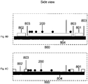
- figure 8 a nanoparticle gradient surface 203 or 700 is present on a chip surface 800, e.g. a glass slide, together with two additional, separate surfaces 801 and 802.
- Figure 8A is a top view and figure 8B and 8C are side views according to two embodiments.
- the two additional, separate surfaces are chemically modified in such a way that one of the surfaces 802 is given the same surface chemistry as the surface with the nanoparticles, whereas the other surface 801 is given the same chemistry as the surface that surrounds the particles in the gradient.
- the operator can examine through a microscope whether the bacteria adsorbs to an area of the gradient surface.
- the operator also obtains information regarding how the bacteria adsorb to surfaces that do not contain nanoparticles but only unmixed surface chemistries. In this way the operator can determine whether the adhesion of the bacteria is related to the presence of nanoparticles or not, and which particle density is necessary for adsorption.
- the different surfaces 203 / 700, 801, an 802 can be separated on the chip 800 with the help of barriers 803 in order to facilitate the use and fabrication of the surface.
- the barriers can be made of engravings or spaces between the surfaces 203/700, 801, and 802 on the chip 800 in such a way that the underlying substrate 804 is exposed. Alternatively, the barriers can consist of ridges between the surfaces 203/700, 801, and 802, specifically in those cases where the particle gradient has been applied on the underlying substrate 804.
- An application of the invention is a product, e.g. a chip comprising a surface, e.g. a glass slide with the three surfaces mentioned above; 1, gold nanoparticle gradient surface where the gold nanoparticle gradient is manufactured on a dithiol modified gold surface on which free dithiols between the particles has reacted with malemide-PEG and the surface of the particles has reacted with a functional thiol, e.g. methyl terminated, amino terminated, acid terminated, or peptide terminated; 2, a gold surface which has been modified dithiol and malemide-PEG; 3, a gold surface which has been modified with the same functional thiol as the surface on the particles.
- a functional thiol e.g. methyl terminated, amino terminated, acid terminated, or peptide terminated
- An application of the invention is a product comprising a surface, e.g. glass slide with the three surfaces mentioned above; 1, gold nanoparticle gradient surface where the gold nanoparticle gradient is manufactured on a dithiol modified gold surface on which free dithiols between the particles has reacted with a malemide-conjugated molecule, e.g. methyl terminated, amino terminated, acid terminated, or peptide terminated, phosphorylated, heterocyclics, aromatics, carbonyles, sugars, inorganics, metal containing particles and the surface of the particles has reacted with a PEG-conjugated thiol.
- a malemide-conjugated molecule e.g. methyl terminated, amino terminated, acid terminated, or peptide terminated, phosphorylated, heterocyclics, aromatics, carbonyles, sugars, inorganics, metal containing particles and the surface of the particles has reacted with a PEG-conjugated thio
- An application of the invention is a product comprising a surface, e.g. glass slide with the three surfaces mentioned above; 1, gold nanoparticle gradient surface where the gold nanoparticle gradient is manufactured on a dithiol modified gold surface on which free dithiols between the particles has reacted with malemide-PEG; 2, a gold surface which has been modified dithiol and malemide-PEG; 3, a pure gold surface.
- the operator can choose which thiol reagent that should be used.
- thiols that can affect adhesion, e.g. thiols conjugated with amino groups, mono- and polysaccharides.
- An application of the invention is a product comprising a surface, e.g. glass slide with the three surfaces mentioned above; 1, gold nanoparticle gradient surface where the gold nanoparticle gradient is manufactured on a dithiol modified gold surface; 2, a gold surface which has been modified dithiol; 3 a pure gold surface.
- a surface e.g. glass slide with the three surfaces mentioned above; 1, gold nanoparticle gradient surface where the gold nanoparticle gradient is manufactured on a dithiol modified gold surface; 2, a gold surface which has been modified dithiol; 3 a pure gold surface.
- An application of the invention is a product comprising a surface, e.g. glass slide with the three surfaces mentioned above; 1, gold nanoparticle gradient surface where the gold nanoparticle gradient is manufactured on a thiol silane modified glass- or silica surface, where free thiol silanes between the particles has reacted with malemide PEG, and where the surface on the particles has reacted with the functional thiol, e.g. methyl terminated, amino terminated, acid terminated, or peptide terminated; 2, a glass or silica surface which has been modified with thiol silane and malemide-PEG; 3, a gold surface which has been modified the same functional thiol as the surface of the particles.
- 1, gold nanoparticle gradient surface where the gold nanoparticle gradient is manufactured on a thiol silane modified glass- or silica surface, where free thiol silanes between the particles has reacted with malemide PEG, and where the surface on the particles has reacted with the functional
- An application of the invention is a product comprising a surface, e.g. glass slide with the three surfaces mentioned above; 1, gold nanoparticle gradient surface where the gold nanoparticle gradient is manufactured on a thiol silane modified glass- or silica surface, where free thiol silanes, between the particles, have reacted with malemide PEG; 2, glass- or silica surface which has been modified with thiol silane and malemide PEG; 3, an unmodified gold surface.
- the operator can choose which thiol reagent to be used.
- An application of the invention is a product comprising a surface, e.g. glass slide with the three surfaces mentioned above; 1, gold nanoparticle gradient surface where the gold nanoparticle gradient is manufactured on a thiol- or aminosilane modified glass- or silica surface, where the silanes under and between the particles has been removed in such a way, e.g. trough plasma treatment, that the particles are sintered on the glass or silica surface where the surfaces between the particles has reacted with PEG-Silane and the surface of the particles has reacted with a functional thiol, e.g.
- An application of the invention is a product comprising a surface, e.g. glass slide with the three surfaces mentioned above; 1, gold nanoparticle gradient surface where the gold nanoparticle gradient is manufactured on a thiol- or aminosilane modified glass- or silica surface and the surface of the particles has reacted with a functional thiol, e.g. PEG terminated, methyl terminated, amino terminated, acid terminated or peptide terminated; 2, a glass or silica surface which has been modified with thiol- or aminosilane; 3, a gold surface which has been modified with the same functional thiol as the surface of the particles.
- a functional thiol e.g. PEG terminated, methyl terminated, amino terminated, acid terminated or peptide terminated
- An application of the invention is a product comprising a surface, e.g. glass slide with the three surfaces mentioned above; 1, gold nanoparticle gradient surface where the gold nanoparticle gradient is manufactured on a thiol- or aminosilane modified glass- or silica surface, where the silanes under and between the particles has been removed in such a way, e.g. trough plasma treatment, that the particles are sintered on the glass or silica surface where the surfaces between the particles have reacted with PEG-Silane; 2, a glass or silica surface which has been modified PEG-Silane; 3, an unmodified gold surface.
- a surface e.g. glass slide with the three surfaces mentioned above; 1, gold nanoparticle gradient surface where the gold nanoparticle gradient is manufactured on a thiol- or aminosilane modified glass- or silica surface, where the silanes under and between the particles has been removed in such a way, e.g. trough plasma treatment, that the particles are sintered on the glass or
- An application of the invention is a product comprising a surface, e.g. glass slide with the three surfaces mentioned above; 1, gold nanoparticle gradient surface where the gold nanoparticle gradient is manufactured on a thiol- or aminosilane modified glass- or silica surface, where the silanes under and between the particles has been removed in such a way, e.g. trough plasma treatment, that the particles are sintered on the glass or silica surface; 2, a glass or silica surface; 3, an unmodified gold surface.
- the operator can choose which surface chemistry and method of modification for the different surfaces.
- the three typical surfaces can in manufacturing be made separate, and then be combined on the glass slides with an adhesive. It is also possible to prepare these surfaces directly on a glass slide.
- FIG. 9A A set up for iSPR analysis of a gradient surface is illustrated in figure 9A .
- An apparatus 900 for imaging SPR such as described in [17], normally controlled with a computer 905, is applied in contact with an SPR-substrate usually comprising a glass surface 901 on which a thin gold layer 902 has been applied.
- a chamber 904 containing a solution is placed, e.g. a buffer in such a way that the gold layer is in contact with the solution.
- the chamber 904 can have an inlet 907 and an outlet 908 and function as a perfusion system to transport solution and analytes to and from the surface.
- the gold surface 902 has been chemically modified with the layer 903 to bind nanoparticles from solution, and a gradient of nanoparticles has been applied to the surface.
- the SPR-response from different positions on the gradient surface can be correlated to partial density at this position.
- bio adhesion e.g. protein-, thrombocyte-, or bacterial adsorption takes place to the gradient surface this can also be detected as an additive response, figure 9B .
- Electrochemical technologies can also be used to estimate the number of nanoparticles on an electrode surface. This specifically is true for conducting nanoparticles for instance gold [19].
- a nanoparticle gradient is applied on a surface 1000 which is made up of n particle binding surfaces 1001 of an electrically conducting material which has been modified with the chemistry 1003 to bind nanoparticles.
- the surfaces 1001 is place on a non-conducting substrate 1002 in such a way that the surfaces 1001 an act as electrodes electrically isolated from one and other.
- the surface 1000 is applied in contact with an electrolyte, e.g. a buffer, in an electrochemical cell 1004 which also can have an inlet 1005 and an outlet 1006 in order to facilitate transportation of electrolyte and analyte to the surface 1000.
- an electrolyte e.g. a buffer
- an electrochemical cell 1004 which also can have an inlet 1005 and an outlet 1006 in order to facilitate transportation of electrolyte and analyte to the surface 1000.
- an electrolyte e.g. a buffer
- an electrochemical cell 1004 which also can have an inlet 1005 and an outlet 1006 in order to facilitate transportation of electrolyte and analyte to the surface 1000.
- an additional reference electrode 1007 and a counter electrode 1008 applied in the electrolyte.
- the electrodes 1007 and or 1008 can also be placed on the surface 1000. All electrodes 1-n on the surface 1000 and in some cases 1007 and 1008, are connected individually by a system for electrochemical reference 10
- the system 1009 could be a system designed for a single type of electrochemical measurements such as impedance measurements.
- the electrochemical response from the different electrodes on the surface 1000 can be measured either between different electrodes on the surface 1000, or by using the electrodes 1007 and 1008 in a conventional tri electrode setup [20].
- the electrochemical response from different electrodes with different positions on the surface 1000 can be correlated to the particle density at this position. If bio adhesion, e.g. cell adhesion, takes place to the gradient surface this can also be detected as an additive, usually a negative, change of the electrochemical response. If a redox active substance comes in contact with the surface this can also be detected as an additive, usually a positive change of the electrochemical response.
- Gold surfaces with size 11 x 20 mm were manufactured by evaporation of first 5 nm Cr and then 200 nm Au on a substrate of SiO2. These were washed and provided with a monolayer of dithiol according to the procedure described in detail [1, 8]. In short, the clean gold surfaces were incubated in a solution of octane dithiol in ethanol where they were reactivated with dithiolthreitol (DDT). An electrostatically stabilized gold particle solution with gold particles around 10 nm in diameter was manufactured according to the procedure described in detail [1, 8]. The gold solution was centrifuged at 16000 g to reduce the ionic strength in the solution, and in order to increase the concentration of the particles.
- DDT dithiolthreitol
- the gold particle pellet was diluted to an approximate particle concentration of 55 nM in pure water with the conductivity of 18.2 M ⁇ *cm.
- This particle solution was transferred to a container designed gradient manufacturing according to figure 5 after which a number of the dithiol prepared surfaces were placed in the same container with a specific distance to the bottom the same. There after a citrate buffer with the concentration 1M and pH 4,0 was placed at the bottom of the gradient container so that the space underneath the surfaces was filled with this buffer. The citrate buffer was then allowed to diffuse over the surfaces during 30 minutes after which the procedure was stopped by emptying the solution from the gradient container from below.
- the citrate buffer with the concentration 50mM was applied underneath the surfaces and was the allowed to diffuse less than 90 minutes which results in a longer gradient with less slope compared to the one obtained with 1 M buffer under 30 minutes.
- the surfaces were analyzed with SEM at different positions on the gradient surface. A selection of pictures is presented in figure 11 .
- Each particle gradient also had reacted with maleimide-PEG in order minimize bioadhesion between the distributed particles, and with octane thiol above the particles which makes the surfaces on the particles hydrophobic in order to promote bio adhesion.
- On each gradient surface an area of app. 1 x 5 mm was analyzed. In these areas all essential parts of the gradient was pictured.
- the SPR wave length presented in the 3D graph z-axis is proportional to the surface coverage of gold nanoparticles.
- a line scan of a "short" gradient is presented together with a line scan for a positive control surface, (in this case a surface modified with only octanedithiol), and a negative control surface modified with octane dithiol and maleimide-PEG.
- Each line scan represents an average of all scans of the surface.
- Example 3 Evaluation of fibrinogen adsorption and thrombocyte adsorption to hydrophobic nanoparticle gradients with iSPR and fluorescence microscopy.
- FIG 14 the response from fibrinogen and thrombocyte adsorption is presented for a gradient surface and a positive controlled surface.
- the blue curve shows the adsorption of fibrinogen
- the green curve the accumulated response from both fibrinogen and thrombocytes.
- the response from the underlying surfaces corresponding to what is shown in figure 13 , has been subtracted from the results in figure 14 .
- the positive surface adsorbs both fibrinogen and thrombocytes homogeneously across the surface, while the gradient surface adsorbs both protein and thrombocytes gradually.
- the negative control surfaces gave no significant response.
- FIG. 15 shows representative thrombocytes at positions with high (A) and low (B) particle coverage respectively.
- Example 4 Evaluation of microbial adhesion to hydrophobic nanoparticle gradients.
Claims (15)
- Ein Verfahren zum Erstellen eines kontinuierlichen Gradienten abgeschiedener und elektrisch geladener Nanopartikel (200) entlang einer festen Oberfläche (203), wobei die Anzahl der abgeschiedenen und elektrisch geladenen Nanopartikel (200) pro Flächeneinheit der Oberfläche (203) an dem einen Ende der Oberfläche relativ hoch ist und an dem gegenüberliegenden Ende der Oberfläche relativ niedrig ist und wobei der Abstand zwischen den abgeschiedenen Partikeln zum Zeitpunkt der Abscheidung durch elektrostatische Abstoßung zwischen den Nanopartikeln in einer Lösung (402) reguliert wird, dadurch gekennzeichnet, dass das Ausmaß der elektrischen Abstoßung von Partikeln in der Lösung (402) durch eine Diffusion einer Salzlösung (403) in die Lösung, die die Nanopartikel (402) enthält, erhalten wird.
- Das Verfahren gemäß Anspruch 1, wobei die Diffusion der Salzlösung (403) durch Ausbilden einer Schicht einer Salzlösung unter einer Schicht einer salzfreien Lösung, die die Nanopartikel (402) enthält, erhalten wird und der kontinuierliche Gradient über die Diffusionszeit und die Konzentration des Salzes in der Salzlösung (403) reguliert wird.
- Das Verfahren gemäß Anspruch 1 oder 2, wobei die Diffusion der Salzlösung (403) durch Halten der Salzlösung (403) in einem Reservoir (603), das in Kontakt mit der Suspension der Nanopartikel (602) angeordnet ist, erhalten wird, wobei diese Suspension außerdem Polysaccharide in einer wasserhaltigen partikulären Form enthält und wobei die Suspension der Nanopartikel (602) in Kontakt mit der festen Oberfläche (203) steht.
- Das Verfahren gemäß einem der vorhergehenden Ansprüche, wobei die Nanoartikel (200) aus Metall, Keramik, wie Glas, oder einem Polymermaterial bestehen und/oder wobei die feste Oberfläche (203) aus Metall, Keramik, wie zum Beispiel Glas, oder einem Polymermaterial besteht.
- Das Verfahren gemäß einem der vorhergehenden Ansprüche, wobei die Bindungskräfte zwischen den Nanopartikeln (200) und der Oberfläche (203) kovalente Bindungen, Coulomb'sche Wechselwirkungen, Metallbindungen, van-der-Waals-Bindungen, Wasserstoffbrückenbindungen, Dipol-Dipol-Bindungen oder lon-Dipol-Bindungen umfassen.
- Das Verfahren gemäß einem der vorhergehenden Ansprüche, wobei die Oberfläche (203) Gold mit einem gebundenen Dithiolreagens ist und die Nanopartikel (200) kovalent an die Thiolgruppen des Dithiolmoleküls gebunden sind, das an die Goldoberfläche gebunden ist.
- Das Verfahren gemäß einem der vorhergehenden Ansprüche, wobei negativ geladene, aber nicht an die Oberfläche bindende Partikel (604) mit oberflächenbindenden Nanopartikeln (200) gemischt werden.
- Das Verfahren gemäß einem der vorhergehenden Ansprüche, außerdem umfassend das Zugeben einer ersten getrennten Oberfläche (801) und einer zweiten getrennten Oberfläche (802) zu der Oberfläche (203), wobei- die Nanopartikel (200) und die erste getrennte Oberfläche (801) denselben Typ einer Verbindung an diese ankonjugiert aufweisen, wobei die Verbindung ausgewählt ist aus der Gruppe bestehend aus Thiolgruppen, wie Thiol mit endständigen Methyl-, endständigen Amino-, endständigen Säure-, endständigen Peptidgruppen, saccharidkonjugiertem oder PEG-konjugiertem Thiol oder Thiolsilan; PEG, wie Poly-L-Lysin-PEG, PEG-modifizierten Silanen, Maleimid-PEG, und Aminosilan und- die Gradientenoberfläche (203) und die zweite getrennte Oberfläche (802) denselben Typ von Verbindungen an diese ankonjugiert aufweisen, wobei die Verbindung ausgewählt ist aus der Gruppe bestehend aus Thiolgruppen, wie Thiol mit endständigen Methyl-, endständigen Amino-, endständigen Säure-, endständigen PeptidGruppen, saccharidkonjugiertem oder PEG-konjugiertem Thiol oder Thiolsilan; PEG, wie Poly-L-Lysin-PEG, PEG-modifizierten Silanen, Maleimid-PEG, und Aminosilan.
- Das Verfahren gemäß einem der vorhergehenden Ansprüche, außerdem umfassend das Anbringen von Skalierungsmarkierungen (702, 703, 704) auf der Oberfläche (203).
- Eine Oberfläche (203, 700) mit einem kontinuierlichen Gradienten abgeschiedener und elektrisch geladener Nanopartikel (200), wobei die Nanopartikel (200) einen mittleren Durchmesser zwischen 10 und 60 nm aufweisen, wobei der durchschnittliche Abstand von Zentrum zu Zentrum der Nanopartikel ungefähr 10 bis 60 nm an dem einen Ende des Gradienten und ungefähr 100 bis 150 nm an dem anderen Ende des Gradienten beträgt.
- Die Oberfläche gemäß Anspruch 10, wobei die Gradientenlänge zwischen 1 mm und 50 mm beträgt und/oder wobei der Gradient linear ist.
- Die Oberfläche gemäß einem der Ansprüche 10 bis 12, wobei die Nanopartikel (200) und/oder die Oberfläche (203) aus Metall, Keramik, wie Glas, oder einem Polymermaterial besteht, wobei bevorzugt die Nanopartikel und/oder die Oberfläche (203) eine Verbindung an diese ankonjugiert aufweisen, wobei die Verbindung bevorzugt ausgewählt ist aus der Gruppe bestehend aus Dithiolgruppen, Thiolgruppen, wie Thiol mit endständigen Methyl-, endständigen Amino-, endständigen Säure-, endständigen PeptidGruppen, saccharidkonjugiertem oder PEG-konjugiertem Thiol oder Thiolsilan; PEG, wie Poly-L-Lysin-PEG, PEG-modifizierten Silanen, Maleimid-PEG, und Aminosilan.
- Ein Chip (800) für die Verwendung bei der Analyse von Adhäsionsphänomenen, wobei der Chip (800) eine Oberfläche (203, 700) gemäß einem der Ansprüche 10 bis 12, eine erste getrennte Oberfläche (801) und eine zweite getrennte Oberfläche (802) aufweist, wobei- die Oberflächen durch Abgrenzungen (803) getrennt sind,- die Nanopartikel (200) und die erste getrennte Oberfläche (801) denselben Typ einer Verbindung an diese ankonjugiert aufweisen, wobei die Verbindung ausgewählt ist aus der Gruppe bestehend aus Thiolgruppen, wie Thiol mit endständigen Methyl-, endständigen Amino-, endständigen Säure-, endständigen Peptidgruppen, saccharidkonjugiertem oder PEG-konjugiertem Thiol oder Thiolsilan; PEG, wie Poly-L-Lysin-PEG, PEG-modifizierten Silanen, Maleimid-PEG, und Aminosilan und- die Gradientenoberfläche (203) und die zweite getrennte Oberfläche (802) denselben Typ von Verbindungen an diese ankonjugiert aufweisen, wobei die Verbindung ausgewählt ist aus der Gruppe bestehend aus Thiolgruppen, wie Thiol mit endständigen Methyl-, endständigen Amino-, endständigen Säure-, endständigen PeptidGruppen, saccharidkonjugiertes oder PEG-konjugiertes Thiol oder Thiolsilan; PEG, wie Poly-L-Lysin-PEG, PEG-modifizierte Silane, Maleimid-PEG, und Aminosilan.
- Der Chip (800) gemäß Anspruch 13, wobei:- die Gradientenoberfläche (203, 700) ein Goldnanopartikelgradient ist, der auf einer thiol- oder aminosilanmodifizierten Glas- oder Quarz(glas)oberfläche hergestellt ist und die Oberfläche der Partikel mit einem funktionellen Thiol, zum Beispiel mit endständigen PEG-, endständigen Methyl-, endständigen Amino-, endständigen Säure- oder endständigen Peptidgruppen reagiert hat,- die erste getrennte Oberfläche (801) eine Goldoberfläche ist, die mit demselben funktionellen Thiol modifiziert worden ist wie die Oberfläche der Partikel, und- die zweite getrennte Oberfläche (802) eine Glas- oder Quarz(glas)oberfläche ist, die mit einem Thiol- oder Aminosilan modifiziert worden ist.
- Verwendung der Oberfläche (203, 700) gemäß den Ansprüchen 10 bis 12 oder der Vorrichtung gemäß Anspruch 13 oder 14 für eine Adhäsionsanalyse, wobei die Analyse auf Oberflächenplasmaresonanz (SPR), Elektrochemie, Lichtmikroskopie oder Rasterelektronenmikroskopie (SEM) basiert.
Applications Claiming Priority (2)
| Application Number | Priority Date | Filing Date | Title |
|---|---|---|---|
| SE1050866A SE535087C2 (sv) | 2010-08-24 | 2010-08-24 | En metod för att preparera en plan yta med en kontrollerad täthetsgradient av deponerade partiklar i nanostorlek |
| PCT/EP2011/064582 WO2012025576A1 (en) | 2010-08-24 | 2011-08-24 | A method for preparing a surface with a controlled coverage of nanograde particles |
Publications (2)
| Publication Number | Publication Date |
|---|---|
| EP2608896A1 EP2608896A1 (de) | 2013-07-03 |
| EP2608896B1 true EP2608896B1 (de) | 2017-12-27 |
Family
ID=44651681
Family Applications (1)
| Application Number | Title | Priority Date | Filing Date |
|---|---|---|---|
| EP11757205.7A Active EP2608896B1 (de) | 2010-08-24 | 2011-08-24 | Verfahren zur präparierung einer oberfläche mit kontrollierter beschichtung aus partikeln in nanogrösse |
Country Status (8)
| Country | Link |
|---|---|
| US (2) | US9566604B2 (de) |
| EP (1) | EP2608896B1 (de) |
| JP (2) | JP6114192B2 (de) |
| CN (1) | CN103180055B (de) |
| DK (1) | DK2608896T3 (de) |
| ES (1) | ES2663833T3 (de) |
| SE (1) | SE535087C2 (de) |
| WO (1) | WO2012025576A1 (de) |
Cited By (1)
| Publication number | Priority date | Publication date | Assignee | Title |
|---|---|---|---|---|
| EP3872168A1 (de) | 2020-02-28 | 2021-09-01 | Cline Scientific AB | Chondrozytendifferenzierung |
Families Citing this family (4)
| Publication number | Priority date | Publication date | Assignee | Title |
|---|---|---|---|---|
| GB201204579D0 (en) * | 2012-03-15 | 2012-05-02 | Univ Nottingham Trent | Coating metal oxide particles |
| EP3091347A1 (de) * | 2015-05-04 | 2016-11-09 | The European Union, represented by the European Commission | Screening von nanopartikeleigenschaften |
| EP4056271A1 (de) | 2021-03-10 | 2022-09-14 | Cline Scientific AB | Quantifizierung der zellmigration und des metastatischen potentials von tumorzellen |
| CN116251951B (zh) * | 2023-03-10 | 2023-11-10 | 清华大学 | 一种基于界面张力梯度-静电引力复合制备金属纳米颗粒自组装层的方法及其应用 |
Family Cites Families (21)
| Publication number | Priority date | Publication date | Assignee | Title |
|---|---|---|---|---|
| US5609907A (en) | 1995-02-09 | 1997-03-11 | The Penn State Research Foundation | Self-assembled metal colloid monolayers |
| US6025202A (en) | 1995-02-09 | 2000-02-15 | The Penn State Research Foundation | Self-assembled metal colloid monolayers and detection methods therewith |
| US6242264B1 (en) | 1996-09-04 | 2001-06-05 | The Penn State Research Foundation | Self-assembled metal colloid monolayers having size and density gradients |
| DE10144252A1 (de) | 2001-08-31 | 2003-03-27 | Fraunhofer Ges Forschung | Nanopartikel mit daran immobilisiertem biologisch aktivem TNF |
| FI118061B (fi) | 2001-09-24 | 2007-06-15 | Beanor Oy | Menetelmä ja bioanturi analyysiä varten |
| DE10200648A1 (de) | 2002-01-10 | 2003-07-24 | Inst Neue Mat Gemein Gmbh | Verfahren zur Herstellung Optischer Elemente mit Gradientenstruktur |
| US6972155B2 (en) | 2002-01-18 | 2005-12-06 | North Carolina State University | Gradient fabrication to direct transport on a surface |
| CN1646912A (zh) | 2002-04-03 | 2005-07-27 | 独立行政法人科学技术振兴机构 | 担载了聚乙二醇化纳米粒子的生物传感器芯片表面 |
| US20060003097A1 (en) | 2003-08-06 | 2006-01-05 | Andres Ronald P | Fabrication of nanoparticle arrays |
| US7750352B2 (en) | 2004-08-10 | 2010-07-06 | Pinion Technologies, Inc. | Light strips for lighting and backlighting applications |
| WO2006080895A1 (en) | 2005-01-20 | 2006-08-03 | Agency For Science, Technology And Research | Water-soluble, surface-functionalized nanoparticle for bioconjugation via universal silane coupling |
| DE102005026485A1 (de) | 2005-06-09 | 2006-12-14 | Bayer Technology Services Gmbh | Hydrophile Nanoteilchen mit funktionellen Oberflächengruppen, deren Herstellung und Verwendung |
| US20070127164A1 (en) | 2005-11-21 | 2007-06-07 | Physical Logic Ag | Nanoscale Sensor |
| FR2893934B1 (fr) | 2005-11-25 | 2008-11-14 | Commissariat Energie Atomique | Dispositif nanostructure |
| EP2351610A3 (de) | 2006-03-28 | 2011-10-12 | Inanovate, Inc. | Biochipsubstrat mit Nanopartikel |
| KR100900955B1 (ko) * | 2006-12-06 | 2009-06-08 | 한국전자통신연구원 | 자기조립된 분자의 커버리지 분석용 기판 및 이를 이용하여자기조립된 분자의 커버리지를 분석하는 방법 |
| WO2008136882A2 (en) * | 2007-02-14 | 2008-11-13 | The Board Of Trustees Of The Leland Stanford Junior University | Fabrication method of size-controlled, spatially distributed nanostructures by atomic layer deposition |
| US20090098366A1 (en) | 2007-09-07 | 2009-04-16 | Northwestern University | Methods of coating surfaces with nanoparticles and nanoparticle coated surfaces |
| US20110245528A1 (en) | 2008-09-23 | 2011-10-06 | Schwartz C Eric | Therapeutic compounds |
| US8267681B2 (en) * | 2009-01-28 | 2012-09-18 | Donaldson Company, Inc. | Method and apparatus for forming a fibrous media |
| CN101993467B (zh) | 2009-08-24 | 2015-12-09 | 香港科技大学 | 在纳米颗粒表面控制功能分子密度的方法 |
-
2010
- 2010-08-24 SE SE1050866A patent/SE535087C2/sv unknown
-
2011
- 2011-08-24 WO PCT/EP2011/064582 patent/WO2012025576A1/en active Application Filing
- 2011-08-24 JP JP2013525302A patent/JP6114192B2/ja active Active
- 2011-08-24 US US13/818,541 patent/US9566604B2/en active Active
- 2011-08-24 ES ES11757205.7T patent/ES2663833T3/es active Active
- 2011-08-24 CN CN201180051333.1A patent/CN103180055B/zh active Active
- 2011-08-24 EP EP11757205.7A patent/EP2608896B1/de active Active
- 2011-08-24 DK DK11757205.7T patent/DK2608896T3/en active
-
2016
- 2016-12-29 US US15/394,140 patent/US10274415B2/en active Active
-
2017
- 2017-03-14 JP JP2017048302A patent/JP6462746B2/ja active Active
Cited By (1)
| Publication number | Priority date | Publication date | Assignee | Title |
|---|---|---|---|---|
| EP3872168A1 (de) | 2020-02-28 | 2021-09-01 | Cline Scientific AB | Chondrozytendifferenzierung |
Also Published As
| Publication number | Publication date |
|---|---|
| US20170241896A1 (en) | 2017-08-24 |
| EP2608896A1 (de) | 2013-07-03 |
| US10274415B2 (en) | 2019-04-30 |
| CN103180055A (zh) | 2013-06-26 |
| JP2017189764A (ja) | 2017-10-19 |
| CN103180055B (zh) | 2014-12-31 |
| SE1050866A1 (sv) | 2012-02-25 |
| JP6462746B2 (ja) | 2019-01-30 |
| JP2013541410A (ja) | 2013-11-14 |
| DK2608896T3 (en) | 2018-03-26 |
| ES2663833T3 (es) | 2018-04-17 |
| SE535087C2 (sv) | 2012-04-10 |
| US9566604B2 (en) | 2017-02-14 |
| US20130180326A1 (en) | 2013-07-18 |
| JP6114192B2 (ja) | 2017-04-12 |
| WO2012025576A1 (en) | 2012-03-01 |
Similar Documents
| Publication | Publication Date | Title |
|---|---|---|
| US10274415B2 (en) | Method for preparing a surface with a controlled coverage of nanograde particles | |
| Dabrowski et al. | Nanostructured molecularly imprinted polymers for protein chemosensing | |
| Colangelo et al. | Characterizing self-assembled monolayers on gold nanoparticles | |
| Zheng et al. | Imparting biomimetic ion-gating recognition properties to electrodes with a hydrogen-bonding structured core− shell nanoparticle network | |
| Nebhani et al. | Orthogonal transformations on solid substrates: efficient avenues to surface modification | |
| de Groot et al. | Smart polymer brush nanostructures guide the self-assembly of pore-spanning lipid bilayers with integrated membrane proteins | |
| Akkahat et al. | Surface-grafted poly (acrylic acid) brushes as a precursor layer for biosensing applications: Effect of graft density and swellability on the detection efficiency | |
| US20080003694A1 (en) | Robust, self-assembled, biocompatible films | |
| Fernandes et al. | Metal-dendrimer hybrid nanomaterials for sensing applications | |
| US20060014013A1 (en) | Stabilized biocompatible supported lipid membrane | |
| Giraud et al. | Amino-functionalized monolayers covalently grafted to silica-based substrates as a robust primer anchorage in aqueous media | |
| Zhu et al. | Monolayer arrays of nanoparticles on block copolymer brush films | |
| Li et al. | Single molecule catch and release: potential-dependent plasmid DNA adsorption along chemically graded electrode surfaces | |
| Taylor et al. | Fabrication of protein dot arrays via particle lithography | |
| JP2011185874A (ja) | 生体分子分析用キット、これを用いた生体分子の分析方法 | |
| KR101836226B1 (ko) | 금 나노입자와 고분자 코팅을 활용한 고효율 바이오칩의 제조방법 및 그에 의한 바이오칩 | |
| US20100015718A1 (en) | Substrate for analyzing coverage of self-assembled molecules and analyzing method using the same | |
| Aleknavičienė et al. | Electrochemical properties of tethered lipid bilayers on thin film silver substrates | |
| Calo et al. | Diffusion-controlled deposition of natural nanovesicles containing G-protein coupled receptors for biosensing platforms | |
| Ktari et al. | Immobilization of magnetic nanoparticles onto conductive surfaces modified by diazonium chemistry | |
| Sopoušek et al. | Thick nanoporous matrices of polystyrene nanoparticles and their potential for electrochemical biosensing | |
| Leïchlé et al. | Nanostructuring surfaces with conjugated silica colloids deposited using silicon-based microcantilevers | |
| Lettieri et al. | DPPTE Thiolipid Self-Assembled Monolayer: A Critical Assay | |
| Lee et al. | Trends in the development and application of functional biomembrane surfaces | |
| Shirahata et al. | An efficient matrix that resists the nonspecific adsorption of protein to fabricate carbohydrate arrays on silicon |
Legal Events
| Date | Code | Title | Description |
|---|---|---|---|
| PUAI | Public reference made under article 153(3) epc to a published international application that has entered the european phase |
Free format text: ORIGINAL CODE: 0009012 |
|
| 17P | Request for examination filed |
Effective date: 20130319 |
|
| AK | Designated contracting states |
Kind code of ref document: A1 Designated state(s): AL AT BE BG CH CY CZ DE DK EE ES FI FR GB GR HR HU IE IS IT LI LT LU LV MC MK MT NL NO PL PT RO RS SE SI SK SM TR |
|
| DAX | Request for extension of the european patent (deleted) | ||
| 17Q | First examination report despatched |
Effective date: 20150226 |
|
| GRAP | Despatch of communication of intention to grant a patent |
Free format text: ORIGINAL CODE: EPIDOSNIGR1 |
|
| RIC1 | Information provided on ipc code assigned before grant |
Ipc: B05D 1/00 20060101ALI20170705BHEP Ipc: B05D 1/18 20060101AFI20170705BHEP Ipc: B05D 1/20 20060101ALI20170705BHEP Ipc: B05D 5/04 20060101ALI20170705BHEP Ipc: G01N 19/04 20060101ALI20170705BHEP Ipc: B82Y 30/00 20110101ALI20170705BHEP Ipc: B05D 5/08 20060101ALI20170705BHEP |
|
| INTG | Intention to grant announced |
Effective date: 20170728 |
|
| GRAS | Grant fee paid |
Free format text: ORIGINAL CODE: EPIDOSNIGR3 |
|
| GRAA | (expected) grant |
Free format text: ORIGINAL CODE: 0009210 |
|
| AK | Designated contracting states |
Kind code of ref document: B1 Designated state(s): AL AT BE BG CH CY CZ DE DK EE ES FI FR GB GR HR HU IE IS IT LI LT LU LV MC MK MT NL NO PL PT RO RS SE SI SK SM TR |
|
| REG | Reference to a national code |
Ref country code: GB Ref legal event code: FG4D |
|
| REG | Reference to a national code |
Ref country code: CH Ref legal event code: EP |
|
| REG | Reference to a national code |
Ref country code: AT Ref legal event code: REF Ref document number: 957860 Country of ref document: AT Kind code of ref document: T Effective date: 20180115 |
|
| REG | Reference to a national code |
Ref country code: IE Ref legal event code: FG4D |
|
| REG | Reference to a national code |
Ref country code: DE Ref legal event code: R096 Ref document number: 602011044553 Country of ref document: DE |
|
| REG | Reference to a national code |
Ref country code: DK Ref legal event code: T3 Effective date: 20180320 |
|
| REG | Reference to a national code |
Ref country code: NL Ref legal event code: FP |
|
| REG | Reference to a national code |
Ref country code: ES Ref legal event code: FG2A Ref document number: 2663833 Country of ref document: ES Kind code of ref document: T3 Effective date: 20180417 |
|
| PG25 | Lapsed in a contracting state [announced via postgrant information from national office to epo] |
Ref country code: LT Free format text: LAPSE BECAUSE OF FAILURE TO SUBMIT A TRANSLATION OF THE DESCRIPTION OR TO PAY THE FEE WITHIN THE PRESCRIBED TIME-LIMIT Effective date: 20171227 Ref country code: NO Free format text: LAPSE BECAUSE OF FAILURE TO SUBMIT A TRANSLATION OF THE DESCRIPTION OR TO PAY THE FEE WITHIN THE PRESCRIBED TIME-LIMIT Effective date: 20180327 Ref country code: FI Free format text: LAPSE BECAUSE OF FAILURE TO SUBMIT A TRANSLATION OF THE DESCRIPTION OR TO PAY THE FEE WITHIN THE PRESCRIBED TIME-LIMIT Effective date: 20171227 |
|
| REG | Reference to a national code |
Ref country code: LT Ref legal event code: MG4D |
|
| REG | Reference to a national code |
Ref country code: AT Ref legal event code: MK05 Ref document number: 957860 Country of ref document: AT Kind code of ref document: T Effective date: 20171227 |
|
| PG25 | Lapsed in a contracting state [announced via postgrant information from national office to epo] |
Ref country code: GR Free format text: LAPSE BECAUSE OF FAILURE TO SUBMIT A TRANSLATION OF THE DESCRIPTION OR TO PAY THE FEE WITHIN THE PRESCRIBED TIME-LIMIT Effective date: 20180328 Ref country code: LV Free format text: LAPSE BECAUSE OF FAILURE TO SUBMIT A TRANSLATION OF THE DESCRIPTION OR TO PAY THE FEE WITHIN THE PRESCRIBED TIME-LIMIT Effective date: 20171227 Ref country code: HR Free format text: LAPSE BECAUSE OF FAILURE TO SUBMIT A TRANSLATION OF THE DESCRIPTION OR TO PAY THE FEE WITHIN THE PRESCRIBED TIME-LIMIT Effective date: 20171227 Ref country code: BG Free format text: LAPSE BECAUSE OF FAILURE TO SUBMIT A TRANSLATION OF THE DESCRIPTION OR TO PAY THE FEE WITHIN THE PRESCRIBED TIME-LIMIT Effective date: 20180327 Ref country code: RS Free format text: LAPSE BECAUSE OF FAILURE TO SUBMIT A TRANSLATION OF THE DESCRIPTION OR TO PAY THE FEE WITHIN THE PRESCRIBED TIME-LIMIT Effective date: 20171227 |
|
| PG25 | Lapsed in a contracting state [announced via postgrant information from national office to epo] |
Ref country code: EE Free format text: LAPSE BECAUSE OF FAILURE TO SUBMIT A TRANSLATION OF THE DESCRIPTION OR TO PAY THE FEE WITHIN THE PRESCRIBED TIME-LIMIT Effective date: 20171227 Ref country code: SK Free format text: LAPSE BECAUSE OF FAILURE TO SUBMIT A TRANSLATION OF THE DESCRIPTION OR TO PAY THE FEE WITHIN THE PRESCRIBED TIME-LIMIT Effective date: 20171227 Ref country code: CZ Free format text: LAPSE BECAUSE OF FAILURE TO SUBMIT A TRANSLATION OF THE DESCRIPTION OR TO PAY THE FEE WITHIN THE PRESCRIBED TIME-LIMIT Effective date: 20171227 Ref country code: CY Free format text: LAPSE BECAUSE OF FAILURE TO SUBMIT A TRANSLATION OF THE DESCRIPTION OR TO PAY THE FEE WITHIN THE PRESCRIBED TIME-LIMIT Effective date: 20171227 |
|
| REG | Reference to a national code |
Ref country code: FR Ref legal event code: PLFP Year of fee payment: 8 |
|
| PG25 | Lapsed in a contracting state [announced via postgrant information from national office to epo] |
Ref country code: SM Free format text: LAPSE BECAUSE OF FAILURE TO SUBMIT A TRANSLATION OF THE DESCRIPTION OR TO PAY THE FEE WITHIN THE PRESCRIBED TIME-LIMIT Effective date: 20171227 Ref country code: AT Free format text: LAPSE BECAUSE OF FAILURE TO SUBMIT A TRANSLATION OF THE DESCRIPTION OR TO PAY THE FEE WITHIN THE PRESCRIBED TIME-LIMIT Effective date: 20171227 Ref country code: RO Free format text: LAPSE BECAUSE OF FAILURE TO SUBMIT A TRANSLATION OF THE DESCRIPTION OR TO PAY THE FEE WITHIN THE PRESCRIBED TIME-LIMIT Effective date: 20171227 Ref country code: IS Free format text: LAPSE BECAUSE OF FAILURE TO SUBMIT A TRANSLATION OF THE DESCRIPTION OR TO PAY THE FEE WITHIN THE PRESCRIBED TIME-LIMIT Effective date: 20180427 Ref country code: PL Free format text: LAPSE BECAUSE OF FAILURE TO SUBMIT A TRANSLATION OF THE DESCRIPTION OR TO PAY THE FEE WITHIN THE PRESCRIBED TIME-LIMIT Effective date: 20171227 |
|
| REG | Reference to a national code |
Ref country code: DE Ref legal event code: R097 Ref document number: 602011044553 Country of ref document: DE |
|
| PLBE | No opposition filed within time limit |
Free format text: ORIGINAL CODE: 0009261 |
|
| STAA | Information on the status of an ep patent application or granted ep patent |
Free format text: STATUS: NO OPPOSITION FILED WITHIN TIME LIMIT |
|
| 26N | No opposition filed |
Effective date: 20180928 |
|
| PG25 | Lapsed in a contracting state [announced via postgrant information from national office to epo] |
Ref country code: SI Free format text: LAPSE BECAUSE OF FAILURE TO SUBMIT A TRANSLATION OF THE DESCRIPTION OR TO PAY THE FEE WITHIN THE PRESCRIBED TIME-LIMIT Effective date: 20171227 |
|
| PG25 | Lapsed in a contracting state [announced via postgrant information from national office to epo] |
Ref country code: MC Free format text: LAPSE BECAUSE OF FAILURE TO SUBMIT A TRANSLATION OF THE DESCRIPTION OR TO PAY THE FEE WITHIN THE PRESCRIBED TIME-LIMIT Effective date: 20171227 |
|
| PG25 | Lapsed in a contracting state [announced via postgrant information from national office to epo] |
Ref country code: LU Free format text: LAPSE BECAUSE OF NON-PAYMENT OF DUE FEES Effective date: 20180824 |
|
| PG25 | Lapsed in a contracting state [announced via postgrant information from national office to epo] |
Ref country code: MT Free format text: LAPSE BECAUSE OF NON-PAYMENT OF DUE FEES Effective date: 20180824 |
|
| PG25 | Lapsed in a contracting state [announced via postgrant information from national office to epo] |
Ref country code: TR Free format text: LAPSE BECAUSE OF FAILURE TO SUBMIT A TRANSLATION OF THE DESCRIPTION OR TO PAY THE FEE WITHIN THE PRESCRIBED TIME-LIMIT Effective date: 20171227 |
|
| PG25 | Lapsed in a contracting state [announced via postgrant information from national office to epo] |
Ref country code: PT Free format text: LAPSE BECAUSE OF FAILURE TO SUBMIT A TRANSLATION OF THE DESCRIPTION OR TO PAY THE FEE WITHIN THE PRESCRIBED TIME-LIMIT Effective date: 20171227 Ref country code: HU Free format text: LAPSE BECAUSE OF FAILURE TO SUBMIT A TRANSLATION OF THE DESCRIPTION OR TO PAY THE FEE WITHIN THE PRESCRIBED TIME-LIMIT; INVALID AB INITIO Effective date: 20110824 |
|
| PG25 | Lapsed in a contracting state [announced via postgrant information from national office to epo] |
Ref country code: SE Free format text: LAPSE BECAUSE OF FAILURE TO SUBMIT A TRANSLATION OF THE DESCRIPTION OR TO PAY THE FEE WITHIN THE PRESCRIBED TIME-LIMIT Effective date: 20171227 Ref country code: IE Free format text: LAPSE BECAUSE OF NON-PAYMENT OF DUE FEES Effective date: 20180824 Ref country code: MK Free format text: LAPSE BECAUSE OF NON-PAYMENT OF DUE FEES Effective date: 20171227 |
|
| PG25 | Lapsed in a contracting state [announced via postgrant information from national office to epo] |
Ref country code: AL Free format text: LAPSE BECAUSE OF FAILURE TO SUBMIT A TRANSLATION OF THE DESCRIPTION OR TO PAY THE FEE WITHIN THE PRESCRIBED TIME-LIMIT Effective date: 20171227 |
|
| PGFP | Annual fee paid to national office [announced via postgrant information from national office to epo] |
Ref country code: NL Payment date: 20230829 Year of fee payment: 13 |
|
| PGFP | Annual fee paid to national office [announced via postgrant information from national office to epo] |
Ref country code: IT Payment date: 20230830 Year of fee payment: 13 Ref country code: GB Payment date: 20230829 Year of fee payment: 13 Ref country code: ES Payment date: 20230905 Year of fee payment: 13 Ref country code: CH Payment date: 20230902 Year of fee payment: 13 |
|
| PGFP | Annual fee paid to national office [announced via postgrant information from national office to epo] |
Ref country code: FR Payment date: 20230829 Year of fee payment: 13 Ref country code: DK Payment date: 20230829 Year of fee payment: 13 Ref country code: DE Payment date: 20230829 Year of fee payment: 13 Ref country code: BE Payment date: 20230829 Year of fee payment: 13 |