EP2605662B1 - Gear box with variably coupled oscillation and rotation for kneading machine - Google Patents
Gear box with variably coupled oscillation and rotation for kneading machine Download PDFInfo
- Publication number
- EP2605662B1 EP2605662B1 EP11818670.9A EP11818670A EP2605662B1 EP 2605662 B1 EP2605662 B1 EP 2605662B1 EP 11818670 A EP11818670 A EP 11818670A EP 2605662 B1 EP2605662 B1 EP 2605662B1
- Authority
- EP
- European Patent Office
- Prior art keywords
- gear
- gear box
- shaft
- primary
- oscillation
- Prior art date
- Legal status (The legal status is an assumption and is not a legal conclusion. Google has not performed a legal analysis and makes no representation as to the accuracy of the status listed.)
- Active
Links
Images

Classifications
-
- B—PERFORMING OPERATIONS; TRANSPORTING
- B29—WORKING OF PLASTICS; WORKING OF SUBSTANCES IN A PLASTIC STATE IN GENERAL
- B29B—PREPARATION OR PRETREATMENT OF THE MATERIAL TO BE SHAPED; MAKING GRANULES OR PREFORMS; RECOVERY OF PLASTICS OR OTHER CONSTITUENTS OF WASTE MATERIAL CONTAINING PLASTICS
- B29B7/00—Mixing; Kneading
- B29B7/30—Mixing; Kneading continuous, with mechanical mixing or kneading devices
- B29B7/34—Mixing; Kneading continuous, with mechanical mixing or kneading devices with movable mixing or kneading devices
- B29B7/36—Mixing; Kneading continuous, with mechanical mixing or kneading devices with movable mixing or kneading devices shaking, oscillating or vibrating
-
- B—PERFORMING OPERATIONS; TRANSPORTING
- B29—WORKING OF PLASTICS; WORKING OF SUBSTANCES IN A PLASTIC STATE IN GENERAL
- B29B—PREPARATION OR PRETREATMENT OF THE MATERIAL TO BE SHAPED; MAKING GRANULES OR PREFORMS; RECOVERY OF PLASTICS OR OTHER CONSTITUENTS OF WASTE MATERIAL CONTAINING PLASTICS
- B29B7/00—Mixing; Kneading
- B29B7/30—Mixing; Kneading continuous, with mechanical mixing or kneading devices
- B29B7/34—Mixing; Kneading continuous, with mechanical mixing or kneading devices with movable mixing or kneading devices
- B29B7/38—Mixing; Kneading continuous, with mechanical mixing or kneading devices with movable mixing or kneading devices rotary
- B29B7/40—Mixing; Kneading continuous, with mechanical mixing or kneading devices with movable mixing or kneading devices rotary with single shaft
- B29B7/42—Mixing; Kneading continuous, with mechanical mixing or kneading devices with movable mixing or kneading devices rotary with single shaft with screw or helix
- B29B7/422—Mixing; Kneading continuous, with mechanical mixing or kneading devices with movable mixing or kneading devices rotary with single shaft with screw or helix with screw sections co-operating, e.g. intermeshing, with elements on the wall of the surrounding casing
- B29B7/423—Mixing; Kneading continuous, with mechanical mixing or kneading devices with movable mixing or kneading devices rotary with single shaft with screw or helix with screw sections co-operating, e.g. intermeshing, with elements on the wall of the surrounding casing and oscillating axially
-
- A—HUMAN NECESSITIES
- A21—BAKING; EDIBLE DOUGHS
- A21C—MACHINES OR EQUIPMENT FOR MAKING OR PROCESSING DOUGHS; HANDLING BAKED ARTICLES MADE FROM DOUGH
- A21C1/00—Mixing or kneading machines for the preparation of dough
- A21C1/14—Structural elements of mixing or kneading machines; Parts; Accessories
- A21C1/1465—Drives
-
- B—PERFORMING OPERATIONS; TRANSPORTING
- B01—PHYSICAL OR CHEMICAL PROCESSES OR APPARATUS IN GENERAL
- B01F—MIXING, e.g. DISSOLVING, EMULSIFYING OR DISPERSING
- B01F27/00—Mixers with rotary stirring devices in fixed receptacles; Kneaders
- B01F27/60—Mixers with rotary stirring devices in fixed receptacles; Kneaders with stirrers rotating about a horizontal or inclined axis
- B01F27/72—Mixers with rotary stirring devices in fixed receptacles; Kneaders with stirrers rotating about a horizontal or inclined axis with helices or sections of helices
- B01F27/721—Mixers with rotary stirring devices in fixed receptacles; Kneaders with stirrers rotating about a horizontal or inclined axis with helices or sections of helices with two or more helices in the same receptacle
- B01F27/722—Mixers with rotary stirring devices in fixed receptacles; Kneaders with stirrers rotating about a horizontal or inclined axis with helices or sections of helices with two or more helices in the same receptacle the helices closely surrounded by a casing
-
- B—PERFORMING OPERATIONS; TRANSPORTING
- B01—PHYSICAL OR CHEMICAL PROCESSES OR APPARATUS IN GENERAL
- B01F—MIXING, e.g. DISSOLVING, EMULSIFYING OR DISPERSING
- B01F27/00—Mixers with rotary stirring devices in fixed receptacles; Kneaders
- B01F27/60—Mixers with rotary stirring devices in fixed receptacles; Kneaders with stirrers rotating about a horizontal or inclined axis
- B01F27/72—Mixers with rotary stirring devices in fixed receptacles; Kneaders with stirrers rotating about a horizontal or inclined axis with helices or sections of helices
- B01F27/721—Mixers with rotary stirring devices in fixed receptacles; Kneaders with stirrers rotating about a horizontal or inclined axis with helices or sections of helices with two or more helices in the same receptacle
- B01F27/723—Mixers with rotary stirring devices in fixed receptacles; Kneaders with stirrers rotating about a horizontal or inclined axis with helices or sections of helices with two or more helices in the same receptacle the helices intermeshing to knead the mixture
-
- B—PERFORMING OPERATIONS; TRANSPORTING
- B01—PHYSICAL OR CHEMICAL PROCESSES OR APPARATUS IN GENERAL
- B01F—MIXING, e.g. DISSOLVING, EMULSIFYING OR DISPERSING
- B01F31/00—Mixers with shaking, oscillating, or vibrating mechanisms
- B01F31/40—Mixers with shaking, oscillating, or vibrating mechanisms with an axially oscillating rotary stirrer
- B01F31/401—Mixers with shaking, oscillating, or vibrating mechanisms with an axially oscillating rotary stirrer for material flowing continuously axially therethrough
-
- B—PERFORMING OPERATIONS; TRANSPORTING
- B29—WORKING OF PLASTICS; WORKING OF SUBSTANCES IN A PLASTIC STATE IN GENERAL
- B29B—PREPARATION OR PRETREATMENT OF THE MATERIAL TO BE SHAPED; MAKING GRANULES OR PREFORMS; RECOVERY OF PLASTICS OR OTHER CONSTITUENTS OF WASTE MATERIAL CONTAINING PLASTICS
- B29B7/00—Mixing; Kneading
- B29B7/30—Mixing; Kneading continuous, with mechanical mixing or kneading devices
- B29B7/34—Mixing; Kneading continuous, with mechanical mixing or kneading devices with movable mixing or kneading devices
- B29B7/38—Mixing; Kneading continuous, with mechanical mixing or kneading devices with movable mixing or kneading devices rotary
- B29B7/40—Mixing; Kneading continuous, with mechanical mixing or kneading devices with movable mixing or kneading devices rotary with single shaft
- B29B7/42—Mixing; Kneading continuous, with mechanical mixing or kneading devices with movable mixing or kneading devices rotary with single shaft with screw or helix
- B29B7/428—Parts or accessories, e.g. casings, feeding or discharging means
- B29B7/429—Screws
-
- B—PERFORMING OPERATIONS; TRANSPORTING
- B29—WORKING OF PLASTICS; WORKING OF SUBSTANCES IN A PLASTIC STATE IN GENERAL
- B29B—PREPARATION OR PRETREATMENT OF THE MATERIAL TO BE SHAPED; MAKING GRANULES OR PREFORMS; RECOVERY OF PLASTICS OR OTHER CONSTITUENTS OF WASTE MATERIAL CONTAINING PLASTICS
- B29B7/00—Mixing; Kneading
- B29B7/30—Mixing; Kneading continuous, with mechanical mixing or kneading devices
- B29B7/58—Component parts, details or accessories; Auxiliary operations
-
- B—PERFORMING OPERATIONS; TRANSPORTING
- B29—WORKING OF PLASTICS; WORKING OF SUBSTANCES IN A PLASTIC STATE IN GENERAL
- B29B—PREPARATION OR PRETREATMENT OF THE MATERIAL TO BE SHAPED; MAKING GRANULES OR PREFORMS; RECOVERY OF PLASTICS OR OTHER CONSTITUENTS OF WASTE MATERIAL CONTAINING PLASTICS
- B29B7/00—Mixing; Kneading
- B29B7/80—Component parts, details or accessories; Auxiliary operations
-
- B—PERFORMING OPERATIONS; TRANSPORTING
- B29—WORKING OF PLASTICS; WORKING OF SUBSTANCES IN A PLASTIC STATE IN GENERAL
- B29C—SHAPING OR JOINING OF PLASTICS; SHAPING OF MATERIAL IN A PLASTIC STATE, NOT OTHERWISE PROVIDED FOR; AFTER-TREATMENT OF THE SHAPED PRODUCTS, e.g. REPAIRING
- B29C45/00—Injection moulding, i.e. forcing the required volume of moulding material through a nozzle into a closed mould; Apparatus therefor
- B29C45/17—Component parts, details or accessories; Auxiliary operations
- B29C45/46—Means for plasticising or homogenising the moulding material or forcing it into the mould
- B29C45/47—Means for plasticising or homogenising the moulding material or forcing it into the mould using screws
- B29C45/50—Axially movable screw
-
- B—PERFORMING OPERATIONS; TRANSPORTING
- B29—WORKING OF PLASTICS; WORKING OF SUBSTANCES IN A PLASTIC STATE IN GENERAL
- B29C—SHAPING OR JOINING OF PLASTICS; SHAPING OF MATERIAL IN A PLASTIC STATE, NOT OTHERWISE PROVIDED FOR; AFTER-TREATMENT OF THE SHAPED PRODUCTS, e.g. REPAIRING
- B29C48/00—Extrusion moulding, i.e. expressing the moulding material through a die or nozzle which imparts the desired form; Apparatus therefor
- B29C48/25—Component parts, details or accessories; Auxiliary operations
- B29C48/252—Drive or actuation means; Transmission means; Screw supporting means
-
- F—MECHANICAL ENGINEERING; LIGHTING; HEATING; WEAPONS; BLASTING
- F16—ENGINEERING ELEMENTS AND UNITS; GENERAL MEASURES FOR PRODUCING AND MAINTAINING EFFECTIVE FUNCTIONING OF MACHINES OR INSTALLATIONS; THERMAL INSULATION IN GENERAL
- F16H—GEARING
- F16H25/00—Gearings comprising primarily only cams, cam-followers and screw-and-nut mechanisms
- F16H25/08—Gearings comprising primarily only cams, cam-followers and screw-and-nut mechanisms for interconverting rotary motion and reciprocating motion
- F16H25/12—Gearings comprising primarily only cams, cam-followers and screw-and-nut mechanisms for interconverting rotary motion and reciprocating motion with reciprocation along the axis of rotation, e.g. gearings with helical grooves and automatic reversal
- F16H25/125—Gearings comprising primarily only cams, cam-followers and screw-and-nut mechanisms for interconverting rotary motion and reciprocating motion with reciprocation along the axis of rotation, e.g. gearings with helical grooves and automatic reversal having the cam on an end surface of the rotating element
-
- F—MECHANICAL ENGINEERING; LIGHTING; HEATING; WEAPONS; BLASTING
- F16—ENGINEERING ELEMENTS AND UNITS; GENERAL MEASURES FOR PRODUCING AND MAINTAINING EFFECTIVE FUNCTIONING OF MACHINES OR INSTALLATIONS; THERMAL INSULATION IN GENERAL
- F16H—GEARING
- F16H37/00—Combinations of mechanical gearings, not provided for in groups F16H1/00 - F16H35/00
- F16H37/12—Gearings comprising primarily toothed or friction gearing, links or levers, and cams, or members of at least two of these types
- F16H37/16—Gearings comprising primarily toothed or friction gearing, links or levers, and cams, or members of at least two of these types with a driving or driven member which both rotates or oscillates on its axis and reciprocates
-
- B—PERFORMING OPERATIONS; TRANSPORTING
- B29—WORKING OF PLASTICS; WORKING OF SUBSTANCES IN A PLASTIC STATE IN GENERAL
- B29C—SHAPING OR JOINING OF PLASTICS; SHAPING OF MATERIAL IN A PLASTIC STATE, NOT OTHERWISE PROVIDED FOR; AFTER-TREATMENT OF THE SHAPED PRODUCTS, e.g. REPAIRING
- B29C45/00—Injection moulding, i.e. forcing the required volume of moulding material through a nozzle into a closed mould; Apparatus therefor
- B29C45/17—Component parts, details or accessories; Auxiliary operations
- B29C45/46—Means for plasticising or homogenising the moulding material or forcing it into the mould
- B29C45/47—Means for plasticising or homogenising the moulding material or forcing it into the mould using screws
- B29C45/50—Axially movable screw
- B29C45/5008—Drive means therefor
- B29C2045/5084—Drive means therefor screws axially driven by roller elements
-
- Y—GENERAL TAGGING OF NEW TECHNOLOGICAL DEVELOPMENTS; GENERAL TAGGING OF CROSS-SECTIONAL TECHNOLOGIES SPANNING OVER SEVERAL SECTIONS OF THE IPC; TECHNICAL SUBJECTS COVERED BY FORMER USPC CROSS-REFERENCE ART COLLECTIONS [XRACs] AND DIGESTS
- Y10—TECHNICAL SUBJECTS COVERED BY FORMER USPC
- Y10T—TECHNICAL SUBJECTS COVERED BY FORMER US CLASSIFICATION
- Y10T74/00—Machine element or mechanism
- Y10T74/18—Mechanical movements
- Y10T74/18024—Rotary to reciprocating and rotary
-
- Y—GENERAL TAGGING OF NEW TECHNOLOGICAL DEVELOPMENTS; GENERAL TAGGING OF CROSS-SECTIONAL TECHNOLOGIES SPANNING OVER SEVERAL SECTIONS OF THE IPC; TECHNICAL SUBJECTS COVERED BY FORMER USPC CROSS-REFERENCE ART COLLECTIONS [XRACs] AND DIGESTS
- Y10—TECHNICAL SUBJECTS COVERED BY FORMER USPC
- Y10T—TECHNICAL SUBJECTS COVERED BY FORMER US CLASSIFICATION
- Y10T74/00—Machine element or mechanism
- Y10T74/19—Gearing
- Y10T74/19642—Directly cooperating gears
Definitions
- the present invention is related to a gear box for a kneading machine which allows coupled oscillation and rotation from a single drive wherein the oscillation strokes per revolution is adjustable but invariant at a given adjustment.
- Kneading machines are widely used in a variety of applications.
- kneading machines can be categorized as either rotational only or rotational and oscillatory.
- the present application is related to a kneader capable of rotating and oscillating which is also referred to in the art as a reciprocating kneader.
- a critical design feature of a reciprocating kneader is the relationship between the rotation and the oscillation.
- stroke ratio is the number of oscillations, or translations parallel to the rotational axis, per rotation of the axis.
- stroke length is the range of motion.
- stroke ratio 2 the oscillation would occur twice with a single rotation.
- the stroke ratio can be a whole number or in some instances it may be a fraction, such as 2.5, wherein five oscillations would occur with two rotations.
- the screw design and, if present, pin arrangement define the stroke ratio and stroke length requirements of a reciprocating kneader. If the stroke ratio and stroke length is not matched to the screw design and pin arrangement the screw flights and pins may collide in catastrophic fashion. As a result, reciprocating kneaders have been considered relatively inflexible with regards to design changes. Reciprocating kneaders are typically designed for a specific application and the design choice often limits the materials which can be kneaded in an existing kneader.
- the rotation and oscillation can be adjusted by using separate drive mechanisms yet this approach has a high failure rate. If one drive mechanism varies, even slightly, the rotation and oscillation lose their synchronous motion which leads to collisions of flights and pins with catastrophic results. Therefore, it is highly desirable that the rotation and oscillation have a common drive to avoid the potential for stroke ratio variability.
- a particular feature of the present invention is the ability to utilize a single drive thereby insuring that the stroke ratio is invariant with regards to rotation rate.
- the gear box has a gear box primary shaft adapted for coupling to a motor.
- a primary rotational gear is attached to the gear box primary shaft and rotates in concert with the gear box primary shaft.
- a secondary rotational gear is engaged with the primary rotation gear and rotates in concert with the primary rotational gear.
- a gear box secondary shaft is attached to the secondary rotational gear and rotates in concert with the secondary rotational gear.
- a primary oscillation gear is attached to the gear box primary shaft and rotates in concert with the gear box primary shaft.
- a secondary oscillation gear is engaged with the primary oscillation gear and rotates in concert with the primary oscillation gear wherein the secondary oscillation gear rotates on the gear box secondary shaft.
- An eccentric comprising at least one lobe is coupled to the secondary oscillation gear and the eccentric rotates in concert with the secondary oscillation gear.
- a yoke is engaged with the eccentric wherein the yoke oscillates on an axis perpendicular to the gear box secondary shaft in response to contact with the lobe of the eccentric during rotation and the gearbox secondary shaft moves along its axis in concert with yoke oscillation.
- a housing is pivotally attached to the yoke at a yoke pivot axis and pivotally attached to a casing at a casing pivot axis herein the yoke pivot axis and the casing pivot axis are not parallel.
- a coupling is on the gear box secondary shaft and adapted for attachment to a screw of a kneader.
- a reciprocating kneader is also provided.
- the reciprocating kneader has a kneader with a cylindrical casing.
- a screw extends into the cylindrical casing wherein the screw has flights and pins extending into the cylindrical casing.
- a gear box is provided.
- the gear box has a gear box primary shaft adapted for coupling to a motor.
- a primary rotational gear is attached to the gear box primary shaft and rotates in concert with the gear box primary shaft.
- a secondary rotational gear is engaged with the primary rotation gear and rotates in concert with the primary rotational gear.
- a gear box secondary shaft is attached to the secondary rotational gear and rotates in concert with the secondary rotational gear.
- a primary oscillation gear is attached to the gear box primary shaft and rotates in concert with the gear box primary shaft.
- a secondary oscillation gear is engaged with the primary oscillation gear and rotates in concert with the primary oscillation gear wherein the secondary oscillation gear rotates on the gear box secondary shaft.
- An eccentric comprising lobes, is coupled to the secondary oscillation gear wherein the eccentric rotates in concert with the secondary oscillation.
- a yoke is engaged with the eccentric wherein the yoke oscillates on an axis perpendicular to the gear box secondary shaft in response to contact with the lobes of the eccentric during rotation and the gearbox secondary shaft moves along its axis in concert with yoke oscillation.
- a housing is pivotally attached to the yoke at a yoke pivot axis and pivotally attached to the casing at a casing pivot axis herein the yoke pivot axis and the casing pivot axis are not parallel.
- the gear box secondary shaft is coupled to the screw such that the screw moves in concert with movement of the gear box secondary shaft.
- a motor is coupled to the gear box primary shaft.
- a gear box for a reciprocating kneader has a casing with a primary shaft extending through the casing.
- a roller plate is attached to the primary shaft wherein the roller plate has circumferentially symmetrically placed deviations from planarity.
- At least one roller assembly is attached to the casing and engaged with the roller plate. Rotation of the roller plate causes the primary shaft to move parallel to rotation relative to the casing in response to engagement between the roller plate and the roller assembly.
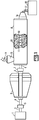
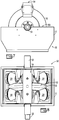
- a drive motor 1, having a motor drive shaft, 3, is the primary source of power for the gear box, 2.
- the motor drive shaft is coupled to a gear box primary shaft, 4, by a primary shaft couple, 5.
- the motor which is not limited herein, may be directly coupled, as illustrated, or coupled through a mechanism such as a transmission, gear assembly, belt assembly or the like without limit herein.
- the drive motor is arranged to rotate the gear box primary shaft.
- the gear box, 2, which will be described more fully herein, has an output coupler, 6, which is coupled to an kneader input shaft, 9, of a reciprocating kneader, 8, by a kneader shaft couple, 7.
- the kneader shaft couple insures that the rotation and oscillation of the output coupler is translated to the kneader input shaft.
- the reciprocating kneader comprises a screw, 10, with a multiplicity of flights, 11, thereon. As the screw rotates and oscillates the flights pass by pins, 12, in close proximity thereby providing the kneading function.
- Precursor material, 14, enters a hopper, 15, wherein it passes into the kneader and exits, optionally through an extrusion die, 16, as extrudate, 17, for collection in a bin, 18.
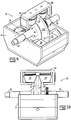
- the gear box, 2 is shown in isolated perspective view in Fig. 2 .
- the gear box comprises upper and lower casing members, 20, suitable for mounting to a frame member, not shown, as would be realized.
- the gear box primary shaft, 4, extends from the rear of the gear box and the output coupler, 6, is accessible on the front of the gear box for coupling thereto.
- Casing bearings are not further described since these would be readily understood to be appropriate and the design thereof is not particularly limiting.
- a pivot pin flange, 21, is on either side of the casing the purpose of which will be more fully understood after further discussion.
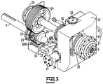
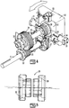
- FIG. 3 An embodiment of the internal components of the gear box is illustrated in front perspective view in Fig. 3 and another embodiment is illustrated in rear perspective in Fig. 4 with the casing removed in both views for clarity.
- the gear box primary shaft, 4 drives rotation and oscillation in concert.
- a bearing, 22, supports the gear box primary shaft in the housing as would be readily appreciated.
- a primary rotational gear, 23, is secured to, and driven by, the gear box primary shaft.
- the primary rotational gear engages with a secondary rotational gear, 24, thereby providing rotation to a gear box secondary shaft, 25.
- the gear box secondary shaft is preferably parallel to the gearbox primary shaft.
- the gear ratio of the primary rotational gear to the secondary rotational gear determines the rate of rotation of the gear box secondary shaft, 25, relative to the gear box primary shaft, 4.
- the gear box secondary shaft is supported by a bearing, 26, which engages with the casing.
- a primary oscillation gear, 27, is secured to, and driven by, the gear box primary shaft.
- the primary oscillation gear engages with a secondary oscillation gear, 28, which rotates freely on the gear box secondary shaft, 25.
- the secondary oscillation gear drives an eccentric, 29.
- the eccentric, 29, has lobes, 30.
- a yoke, 31, rides on the eccentric. As the eccentric rotates the yoke transfers the pattern of the lobe to a housing, 32.
- the yoke pivots on a secondary pivot axis, 33, within the housing and the housing pivots on a primary pivot sleeve, 34, which is secured to the casing by bearings (not shown) and bound by the pivot pin flange, 21.
- the primary pivot sleeve, 34 is offset relative to the gear box secondary shaft which causes the housing to oscillate back and forth along the arrow in Fig. 4 on the axis defined by the primary pivot sleeves.
- the length of the oscillation is dependent on the angle of the lobes on the eccentric and the distance between the primary pivot sleeve and the axis of the gear box secondary shaft. In general, the stroke length increases as the angle of the eccentric increases and as the distance from the center line of the gear box secondary shaft to the primary pivot sleeve increases.
- a preferred output coupler bearing housing, 35 contains the output coupler, 6, and provides an attachment point for the kneader.
- the secondary oscillation gear and eccentric may rotate at a different rate than the gear box secondary shaft. Therefore, they must rotate freely on the gear box secondary shaft and be free to move along the gear box secondary shaft.
- a tertiary gear, 350 may function as an idler roller or it may turn an oil pump, 36, or other auxiliary equipment, diagnostic equipment or the like.
- Auxiliary equipment and diagnostic equipment may include lubrication monitors, tachometers, hour monitors and the like.
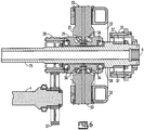
- FIG. 6 A portion of the internal components of the gear box is illustrated in cross-sectional side schematic view in Fig. 6 .
- the eccentric, 29, rotates freely on the gear box secondary shaft, 25.
- the eccentric and gear box secondary shaft have secondary shaft bearings, 36, there between to reduce rotational friction between the eccentric and a land, 38, of the gear box secondary shaft.
- the secondary shaft bearings are preferably spherical roller thrust bearings.
- the output coupler, 6, and output coupler bearing housing, 35 have a coupler housing bearing, 37, there between to reduce rotational friction.
- a particularly preferred coupler housing bearing is a toroidal bearing.
- a feature of the present invention is the constant correlation of rotation and oscillation thereby prohibiting catastrophic contact between flights and pins.
- the primary rotational gear and primary oscillation gear are secured to the gear box primary shaft in such a way that they do not rotate on the gear box primary shaft independent of each other.
- the primary rotational gear and primary oscillation gear are preferably reversibly attached to the gear box primary shaft by keyways, mating surface shapes, threaded members and the like.
- the union between the primary rotation gear and secondary rotation gear, the union between the primary oscillation gear and secondary oscillation gear, the union between the secondary rotation gear and the gear box secondary shaft and the union between the secondary oscillation gear and eccentric are preferably unions which prohibit slip.
- Belts can be incorporated but are not preferred unless they are a toothed belt, with protrusion on the inside, mated with a geared wheel. Mating primary and secondary gears such as toothed gears are a preferred embodiment. Chain assemblies are another preferred embodiment.
- a particular feature of the invention is the ability to change the stroke.
- the stroke length can be changed by replacing the eccentric.
- the stroke ratio can be changed by changing the gear ratio of the primary oscillation gear to secondary oscillation gear, by changing the gear ratio of the primary rotation gear to secondary rotational gear or combinations thereof.
- the rotation rate of the gear box primary shaft, 4 is determined by the motor attached thereto.
- a rotation rate of the gear box primary shaft of 1800 rpm is considered.
- the rotation rate of the screw within the kneader will be the same as the rotation rate of the gear box secondary shaft which is determined by the gear ratio of the primary rotation gear to the secondary rotation gear.
- a gear ratio of the secondary rotational gear to the primary rotational gear could be 2:1 thereby providing a rotation rate for the gear box secondary shaft which is half of the rotation rate of the gear box primary shaft.
- the rotation rate of the kneader screw would be 900 rpm.
- the oscillation rate of the screw would be determined by the number of lobes on the eccentric and the rotation rate of the eccentric.
- the eccentric may have a single lobe wherein one rotation of the eccentric creates one oscillation of the screw.
- the oscillation rate would therefore be determined by the rotation rate of the eccentric.
- the eccentric is coupled to the gear box primary shaft and defined by the ratio of the primary oscillation gear to the secondary oscillation gear. Again for illustration purposes, if the ratio of the primary oscillation gear to the secondary oscillation gear is 1.5:1 the eccentric rotates at a rate of 2700 rpm which is three times that of the gear box secondary shaft.
- the result in this example is 3 oscillations per rotation for a stroke ratio of 3.
- a particular feature of the invention is that the stroke ratio is invariant to motor speed or the rotational rate of the gear box primary shaft thereby eliminating collision opportunities within the kneader. Any disturbance in speed of the motor, such as by power supply fluctuations, would result in a change in the rotation rate of the kneader screw and rate of oscillations but there would be no alteration in the stroke ratio.
- FIG. 7-10 Another non-claimed embodiment of a gearbox is illustrated in schematic partial view in Figs. 7-10 .
- the lower casing, 51 is illustrated and the upper casing is removed for clarity.
- the gearbox, 50 is illustrated in front view in Fig. 7 , top view in Fig. 8 , perspective side view in Fig. 9 , and side view in Fig. 10 .
- the gear box, 50 comprises a primary shaft, 52, which is continuous through the gear box.
- a motor attaches to the primary shaft at a sliding couple, 53.
- the sliding couple couples the rotation of the primary shaft to the motor while allowing the primary shaft to oscillate parallel to the motor shaft.
- the sliding couple may be a direct connection between the motor and primary shaft or it may be an offset couple employing gears, pulleys, chains, a transmission or the like.
- the roller plate comprises deviations from planarity which are symmetrically placed circumferentially. It is particularly preferred that the deviations from planarity are on opposing sides of the center plane of the roller plates in a sinusoidal fashion. It is particularly preferred that the edge, 55, have a sin(sin(x)) sinusoidal pattern.
- Roller assemblies, 54, attached to the casing, 51, are arranged at the same frequency as the deviations from planarity.
- the roller assembly comprises a bracket, 58, with rollers, 59, attached thereto.
- the bracket is secured to the casing.
- the rollers form a limited path for passage of the roller plate. As the roller plate passes through the rollers the primary shaft is persuaded to move parallel to the axis of rotation due to the force applied to the roller plate by the roller.
- the deviations from planarity are separated by 120 degrees as are the roller assemblies.
- the shaft will be forced to move linearly relative to the roller assemblies, and casing, in response to the deviations from planarity.
- the number of occurrences of deviation from planarity determines the stroke of the gear box.
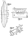
- a representative roller plate is illustrated in Fig. 11 .
- three deviations are illustrated wherein the deviations are separated by 120°.
- a gear box with a roller plate as illustrated in Fig. 11 would generate 3 strokes per revolution. For the purposes of discussion deviations are defined based on the center line.
- the gear box With two deviations, which would be separated by 180°, the gear box would generate 2 strokes per revolution. With four deviations, which would be separated by 90°, the gear box would generate four strokes per revolution. The length of each stroke would be determined by the amount of deviation from planarity. The larger the deviation from planarity the longer the stroke.
- roller assemblies are arranged at fixed intervals based on the number of deviations.
- the number of roller assemblies is no more than one roller per deviation and they are placed symmetrically with the same frequency as the number of deviations.
- fewer roller assemblies can be employed than the number of deviations as long as they are disposed symmetrically in a manner which matches the frequency of deviation.
- the roller plate has four deviations they would be displaced at 90° intervals around the roller plate.
- Four roller assemblies could be used with the four roller plate deviations placed in 90° intervals.
- select roller assemblies could be eliminated.
- three roller assemblies could be used placed at intervals of 90°-90°-90°-180°.
- two roller assemblies could be used with spacings of 90° or 180° intervals.
- a single roller assembly could be used.
- the kneader screw would be coupled to the primary shaft with a union which fixes the rotation and oscillation to the shaft.
- the mixing chamber, 120 comprises a multiplicity of voids, 121, through which pins, 122, extend.
- the pins are attached to a rail, 123.
- the rail, 123 preferably resides in a slot, 124, thereby maintaining a surface on the mixing chamber with minimum deviations from a round exterior.
- a particular advantage of the embodiment illustrated in Fig. 12 is the ability to insert a large number of pins simultaneously.
- the mixing chamber, 120 may be encased in an outer sleeve, either completely or partially, thereby securing the rail within the slot. Alternatively, the rail may be secured by threaded members.
- the pin rail may be installed on the interior of the mixing chamber but this is less preferred.
- the screw may comprise a cylindrical screw shaft with continuous wings or portions of wings on the exterior thereof.
- the pitch of the wings may vary with length thereby providing different kneading characteristics along the flow path.
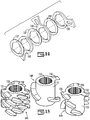
- a screw shaft, 130 comprises a cylindrical core, 131, with outward protrusions, 132, symmetrically attached thereto.
- a segmented flight, 133 slides on the screw shaft.
- the segmented flight, 133 has a center void, 134, which receives the cylindrical core of the screw shaft. Depressions, 135, in the center void mate with the protrusions to prohibit rotation of the segmented flight on the screw shaft.
- the segmented flight has a wing, 136, thereon which kneads the material, optionally, by passing into close proximity with pins as described above.
- the segmented flight can be placed in a limited number of rotational orientations based on the number of protrusions and depressions. As illustrated, the segmented flight can be placed in one of three rotational positions. An advantage of this is described with reference to Fig. 14 wherein three segmented flights, 133, are shown in exploded view as they would be oriented on a screw shaft. Each one is rotated 120° relative to the adjacent segmented flight. Spacers, 137, between segmented flights define the separation. By varying the thickness of the segmented flight, the pitch of the wing, and the spacers a great variety of kneading conditions can be established. Furthermore, a damaged flight can be easily replaced. While illustrated with protrusions on the shaft and matching depressions on the segmented flight this arrangement can be reversed.
- FIG. 15 multiple wing sleeves, 149, with each comprising multiple wings, 150, and multiple orientations are illustrated attached to a cylindrical core, 151.
- the cylindrical core is preferably placed on a shaft, not shown, wherein the shaft comprises teeth which mate with the teeth, 152, in the central cavity of the wing.
- the kneading pattern can be adjusted by the use of wing sleeves in various configurations.
Landscapes
- Engineering & Computer Science (AREA)
- Mechanical Engineering (AREA)
- General Engineering & Computer Science (AREA)
- Chemical Kinetics & Catalysis (AREA)
- Chemical & Material Sciences (AREA)
- Life Sciences & Earth Sciences (AREA)
- Food Science & Technology (AREA)
- Manufacturing & Machinery (AREA)
- Mixers Of The Rotary Stirring Type (AREA)
- Processing And Handling Of Plastics And Other Materials For Molding In General (AREA)
- Transmission Devices (AREA)
- Mixers With Rotating Receptacles And Mixers With Vibration Mechanisms (AREA)
- Accessories For Mixers (AREA)
- Gear Transmission (AREA)
Applications Claiming Priority (2)
| Application Number | Priority Date | Filing Date | Title |
|---|---|---|---|
| US12/857,001 US8807825B2 (en) | 2010-08-16 | 2010-08-16 | Gear box with variably coupled oscillation and rotation for kneading machine |
| PCT/US2011/047937 WO2012024307A2 (en) | 2010-08-16 | 2011-08-16 | Gear box with variably coupled oscillation and rotation for kneading machine |
Publications (3)
| Publication Number | Publication Date |
|---|---|
| EP2605662A2 EP2605662A2 (en) | 2013-06-26 |
| EP2605662A4 EP2605662A4 (en) | 2016-07-13 |
| EP2605662B1 true EP2605662B1 (en) | 2018-01-10 |
Family
ID=45564741
Family Applications (1)
| Application Number | Title | Priority Date | Filing Date |
|---|---|---|---|
| EP11818670.9A Active EP2605662B1 (en) | 2010-08-16 | 2011-08-16 | Gear box with variably coupled oscillation and rotation for kneading machine |
Country Status (9)
| Country | Link |
|---|---|
| US (5) | US8807825B2 (enExample) |
| EP (1) | EP2605662B1 (enExample) |
| JP (2) | JP5665990B2 (enExample) |
| CN (1) | CN103153069B (enExample) |
| BR (1) | BR112013003770B1 (enExample) |
| CA (2) | CA2908468C (enExample) |
| MX (3) | MX339725B (enExample) |
| SG (1) | SG187825A1 (enExample) |
| WO (1) | WO2012024307A2 (enExample) |
Families Citing this family (11)
| Publication number | Priority date | Publication date | Assignee | Title |
|---|---|---|---|---|
| US8807825B2 (en) * | 2010-08-16 | 2014-08-19 | B&P Process Equipment And Systems, Llc | Gear box with variably coupled oscillation and rotation for kneading machine |
| US9862121B2 (en) * | 2012-12-17 | 2018-01-09 | B&P Littleford Llc | Kneading method and apparatus |
| US9919279B2 (en) | 2012-12-17 | 2018-03-20 | B&P Littleford Llc | Shaft spacing flange for a kneading machine |
| CN105415057A (zh) * | 2015-10-09 | 2016-03-23 | 滁州品之达电器科技有限公司 | 一种特种数控开槽机 |
| CN105435693B (zh) * | 2016-01-12 | 2018-06-26 | 尚鲁强 | 医用振荡器 |
| RU181561U1 (ru) * | 2018-03-12 | 2018-07-19 | Закрытое акционерное общество Научно - инженерный центр "ИНКОМСИСТЕМ" | Устройство преобразования поступательного движения во вращательное с возвратно-поступательным |
| CN108339480A (zh) * | 2018-03-29 | 2018-07-31 | 浙江宜佳新材料股份有限公司 | 一种辐照交联卷材加工用混料设备 |
| KR102361881B1 (ko) * | 2020-04-27 | 2022-02-11 | 용 석 장 | 반죽기용 감속장치 |
| CN112169739A (zh) * | 2020-10-19 | 2021-01-05 | 江西金凯化工有限公司 | 一种高安全的化工搅拌反应釜 |
| CN115096063B (zh) * | 2022-05-25 | 2023-06-02 | 广州市通四海生物科技有限公司 | 一种酒厂废弃物资源再利用流水生产线及控制方法 |
| US12228980B2 (en) * | 2022-12-12 | 2025-02-18 | Quanta Computer Inc. | Mounting system for an electronic device |
Family Cites Families (50)
| Publication number | Priority date | Publication date | Assignee | Title |
|---|---|---|---|---|
| US2547151A (en) * | 1945-09-15 | 1951-04-03 | Albert H Braeseke | Extruding machine |
| US2629132A (en) | 1950-10-27 | 1953-02-24 | Gen Electric | Molding apparatus |
| US2801237A (en) * | 1952-10-15 | 1957-07-30 | Rhodiaceta | Continuous process for the esterification of cellulose in homogeneous phase |
| US2916769A (en) | 1953-06-05 | 1959-12-15 | R H Windsor Ltd | Injection moulding machines |
| US3115681A (en) | 1961-06-28 | 1963-12-31 | Borg Warner | Fluted ram and fluted extruder |
| US3133316A (en) | 1961-08-07 | 1964-05-19 | Pennsalt Chemicals Corp | Molding apparatus |
| NL283627A (enExample) | 1962-09-26 | 1900-01-01 | ||
| DE1241417B (de) | 1962-09-28 | 1967-06-01 | Buss Ag | Kontinuierlich arbeitende Misch- und Kneteinrichtung |
| ES295777A1 (es) * | 1963-01-28 | 1964-05-01 | Dacco Ernesto | Maquina para el moldeo por inyecciën a presiën de materiales termoplasticos |
| GB1052514A (enExample) | 1963-03-11 | 1900-01-01 | ||
| US3253818A (en) | 1963-06-17 | 1966-05-31 | Celanese Corp | Mixing and shearing apparatus |
| US3317962A (en) | 1965-03-17 | 1967-05-09 | Injection Molders Supply Co In | Injection machine positive stop |
| JPS519936B1 (enExample) * | 1966-02-08 | 1976-03-31 | ||
| US3456298A (en) | 1967-01-18 | 1969-07-22 | Xaloy Inc | Pressure balancing means for cylinders for injection molding and extrusion |
| US3443446A (en) | 1967-01-25 | 1969-05-13 | George K Buergel | Reciprocating motion creating double thrust ball bearing |
| US3570588A (en) | 1968-12-12 | 1971-03-16 | Baker Perkins Inc | Methods and apparatus for cooling mixes such as carbonaceous particle-pitch masses being blended |
| CH512987A (de) | 1969-09-04 | 1971-09-30 | Buehler Ag Geb | Verfahren und Vorrichtung zum Spritzgiessen von Kunststoff zu geschäumten Gegenständen |
| US3734667A (en) | 1970-09-30 | 1973-05-22 | Extruders Inc | Plastic extrusion apparatus |
| GB1390190A (en) | 1971-07-01 | 1975-04-09 | Wisz E | Mixing apparatus and method |
| CH528294A (de) * | 1971-10-28 | 1972-09-30 | Buss Ag | Satz von Schneckenmaschinen und Verfahren zum Betrieb der Maschinen |
| CH544602A (de) | 1971-12-10 | 1973-11-30 | Btr Osam Kam Dso Zmm | Pinolenantriebskopf zum Arbeiten in Zyklen mit kurzer Zeitdauer |
| US3802278A (en) * | 1972-01-24 | 1974-04-09 | Baker Perkins Inc | Mixer drive mechanism |
| DE2264315A1 (de) | 1972-12-30 | 1974-07-04 | Krauss Maffei Ag | Rotations- und vorschubantriebsvorrichtung fuer eine spritzgiessmaschine |
| CH576086A5 (en) | 1973-07-23 | 1976-05-31 | Buss Ag | Simultaneously rotating and axially reciprocating drive shaft - for screw conveyors, agitators etc is also fitted with wobble plate |
| US3862551A (en) | 1973-09-12 | 1975-01-28 | Baker Perkins Inc | Drive shaft construction for mixers and the like |
| JPS519936A (ja) | 1974-06-25 | 1976-01-27 | Chizuru Watanabe | Jitenshasokorenshusochi |
| US4099899A (en) | 1976-06-28 | 1978-07-11 | Phillips Petroleum Company | Carbon black pelleter |
| ES233279Y (es) | 1978-01-16 | 1978-11-16 | Prensa continua para uvas y frutos. | |
| JPS5610854A (en) * | 1979-07-02 | 1981-02-03 | Fukao Sakata | Conversion mechanism for rotating and reciprocating movements |
| DE3150719C2 (de) * | 1981-12-22 | 1987-04-02 | Uniroyal Englebert Reifen GmbH, 5100 Aachen | Schneckenextruder |
| EP0102400B1 (de) * | 1982-08-26 | 1987-01-14 | HERMANN BERSTORFF Maschinenbau GmbH | Entgasungsextruder |
| JPS61277410A (ja) | 1985-06-03 | 1986-12-08 | Nippei Toyama Corp | 推力方向往復運動装置の圧力補償装置 |
| CH672057A5 (enExample) | 1987-06-22 | 1989-10-31 | Gianfranco Passoni | |
| US4976904A (en) * | 1989-04-20 | 1990-12-11 | Energy Research Corporation | Method and apparatus for continuous formation of fibrillated polymer binder electrode component |
| JP3179086B2 (ja) | 1990-03-07 | 2001-06-25 | 冷化工業株式会社 | 混合装置 |
| DE4106998C2 (de) | 1990-03-07 | 1997-08-14 | Reica Corp | Mischvorrichtung |
| JPH1082457A (ja) | 1996-09-06 | 1998-03-31 | Matsushita Electric Ind Co Ltd | スパイラル動作装置 |
| US5789830A (en) * | 1997-07-08 | 1998-08-04 | Systems, Machines, Automation Components Corporation | In-line rotational drive |
| US7070318B2 (en) | 2000-05-02 | 2006-07-04 | Renfro Charles K | Mixing apparatus having rotational and axial motion |
| US6431755B1 (en) * | 2000-08-11 | 2002-08-13 | Loren T. Schneider | Drive train for use with a kneader apparatus |
| JP2005131578A (ja) | 2003-10-31 | 2005-05-26 | Reika Kogyo Kk | 撹拌混合装置 |
| ITVI20050187A1 (it) | 2005-06-28 | 2006-12-29 | Tecres Spa | Cartuccia per la miscelazione sterile di un composto bifasico, perticolarmente per resine acriliche bicomponenti |
| DE102005034278A1 (de) * | 2005-07-22 | 2007-04-12 | Daimlerchrysler Ag | Antriebseinheit für ein Fahrzeug |
| US20070140054A1 (en) | 2005-12-16 | 2007-06-21 | Stocker Stephen D | Quick-disconnect mixer drive system |
| TWI284560B (en) | 2006-01-26 | 2007-08-01 | Mao-Hsin Huang | Mixing device for beverage dispenser |
| DE502007000130D1 (de) | 2006-02-06 | 2008-11-13 | Buss Ag | Misch- und Knetmaschine |
| JP4961225B2 (ja) * | 2007-02-07 | 2012-06-27 | 荻野工業株式会社 | 揺動型歯車装置 |
| PT2018946T (pt) | 2007-07-25 | 2017-03-15 | Buss Ag | Máquina de misturar e amassar para processos de preparação contínua, e procedimento para execução de processos de preparação contínua por intermédio de uma máquina de misturar e amassar |
| US8807825B2 (en) * | 2010-08-16 | 2014-08-19 | B&P Process Equipment And Systems, Llc | Gear box with variably coupled oscillation and rotation for kneading machine |
| CN202161960U (zh) | 2011-07-15 | 2012-03-14 | 江苏华东明茂机械有限公司 | 一种具有十字滑块联轴器的搅拌机 |
-
2010
- 2010-08-16 US US12/857,001 patent/US8807825B2/en active Active
-
2011
- 2011-08-16 WO PCT/US2011/047937 patent/WO2012024307A2/en not_active Ceased
- 2011-08-16 MX MX2013001625A patent/MX339725B/es active IP Right Grant
- 2011-08-16 EP EP11818670.9A patent/EP2605662B1/en active Active
- 2011-08-16 JP JP2013524930A patent/JP5665990B2/ja active Active
- 2011-08-16 CA CA2908468A patent/CA2908468C/en active Active
- 2011-08-16 BR BR112013003770-9A patent/BR112013003770B1/pt not_active IP Right Cessation
- 2011-08-16 CN CN201180048330.2A patent/CN103153069B/zh active Active
- 2011-08-16 CA CA2808122A patent/CA2808122C/en active Active
- 2011-08-16 SG SG2013010517A patent/SG187825A1/en unknown
-
2013
- 2013-02-08 MX MX2022011398A patent/MX2022011398A/es unknown
- 2013-02-08 MX MX2022013349A patent/MX2022013349A/es unknown
- 2013-12-16 US US14/107,023 patent/US9566719B2/en active Active
-
2014
- 2014-06-27 JP JP2014132640A patent/JP2014240067A/ja active Pending
- 2014-08-07 US US14/454,242 patent/US9592624B2/en active Active
-
2017
- 2017-03-13 US US15/457,409 patent/US10611055B2/en active Active
-
2020
- 2020-04-01 US US16/837,378 patent/US20210053252A1/en not_active Abandoned
Non-Patent Citations (1)
| Title |
|---|
| None * |
Also Published As
| Publication number | Publication date |
|---|---|
| EP2605662A2 (en) | 2013-06-26 |
| CA2808122C (en) | 2016-05-31 |
| MX339725B (es) | 2016-06-07 |
| WO2012024307A3 (en) | 2012-05-31 |
| US20120039145A1 (en) | 2012-02-16 |
| JP2014240067A (ja) | 2014-12-25 |
| US9592624B2 (en) | 2017-03-14 |
| CA2808122A1 (en) | 2012-02-23 |
| BR112013003770B1 (pt) | 2018-07-31 |
| US20210053252A1 (en) | 2021-02-25 |
| SG187825A1 (en) | 2013-03-28 |
| CA2908468C (en) | 2017-05-09 |
| JP2013540571A (ja) | 2013-11-07 |
| CA2908468A1 (en) | 2012-02-23 |
| WO2012024307A2 (en) | 2012-02-23 |
| BR112013003770A2 (pt) | 2016-05-31 |
| CN103153069A (zh) | 2013-06-12 |
| EP2605662A4 (en) | 2016-07-13 |
| JP5665990B2 (ja) | 2015-02-04 |
| US10611055B2 (en) | 2020-04-07 |
| MX2022013349A (es) | 2022-12-13 |
| US20150124551A1 (en) | 2015-05-07 |
| MX2022011398A (es) | 2022-10-13 |
| US20170297226A1 (en) | 2017-10-19 |
| US8807825B2 (en) | 2014-08-19 |
| MX2013001625A (es) | 2013-06-05 |
| CN103153069B (zh) | 2015-02-25 |
| US20140102232A1 (en) | 2014-04-17 |
| US9566719B2 (en) | 2017-02-14 |
Similar Documents
| Publication | Publication Date | Title |
|---|---|---|
| EP2605662B1 (en) | Gear box with variably coupled oscillation and rotation for kneading machine | |
| US9862121B2 (en) | Kneading method and apparatus | |
| US12146558B2 (en) | Plate-shaped harmonic reducer | |
| JPH0861450A (ja) | 遊星ローラ式変速機構を用いた動力伝達装置 | |
| EP1005969B1 (en) | Rotor for mixing elastomers having a variable flange or flight angle | |
| EP4470747A1 (en) | An element and a screw for a counter-rotating twin-screw processor | |
| US5103689A (en) | Co-rotating dual outputs twin screw extruder with axial offset pinions | |
| CN103119301B (zh) | 旋转活塞泵和用于运行旋转活塞泵的方法 | |
| HK1186067A (en) | Gear box with variably coupled oscillation and rotation for kneading machine | |
| KR102171148B1 (ko) | 모노펌프 타입 액체정량토출장치 | |
| US3862551A (en) | Drive shaft construction for mixers and the like | |
| KR20240006783A (ko) | 압출스크류의 조절부를 갖는 식품 압출기 | |
| US20200011405A1 (en) | Ball type speed reducer | |
| JP2024148632A (ja) | 連続式混練装置 | |
| JP2002070846A (ja) | すべり軸受け及びこれを用いたギヤポンプ | |
| RU1789750C (ru) | Регулируемый привод плунжерного насоса | |
| JPH10266977A (ja) | ローター型ポンプ | |
| RU2001125213A (ru) | Планетарно-цевочный редуктор |
Legal Events
| Date | Code | Title | Description |
|---|---|---|---|
| PUAI | Public reference made under article 153(3) epc to a published international application that has entered the european phase |
Free format text: ORIGINAL CODE: 0009012 |
|
| 17P | Request for examination filed |
Effective date: 20130318 |
|
| AK | Designated contracting states |
Kind code of ref document: A2 Designated state(s): AL AT BE BG CH CY CZ DE DK EE ES FI FR GB GR HR HU IE IS IT LI LT LU LV MC MK MT NL NO PL PT RO RS SE SI SK SM TR |
|
| DAX | Request for extension of the european patent (deleted) | ||
| RIC1 | Information provided on ipc code assigned before grant |
Ipc: F16H 37/16 20060101ALI20160307BHEP Ipc: B01F 7/08 20060101AFI20160307BHEP Ipc: F16H 25/12 20060101ALI20160307BHEP Ipc: B01F 11/00 20060101ALI20160307BHEP |
|
| A4 | Supplementary search report drawn up and despatched |
Effective date: 20160615 |
|
| RIC1 | Information provided on ipc code assigned before grant |
Ipc: F16H 25/12 20060101ALI20160609BHEP Ipc: B01F 11/00 20060101ALI20160609BHEP Ipc: F16H 37/16 20060101ALI20160609BHEP Ipc: B01F 7/08 20060101AFI20160609BHEP |
|
| RAP1 | Party data changed (applicant data changed or rights of an application transferred) |
Owner name: B&P LITTLEFORD LLC |
|
| REG | Reference to a national code |
Ref country code: DE Ref legal event code: R079 Ref document number: 602011045061 Country of ref document: DE Free format text: PREVIOUS MAIN CLASS: A21C0001140000 Ipc: B01F0007080000 |
|
| GRAP | Despatch of communication of intention to grant a patent |
Free format text: ORIGINAL CODE: EPIDOSNIGR1 |
|
| RIC1 | Information provided on ipc code assigned before grant |
Ipc: B01F 11/00 20060101ALI20170713BHEP Ipc: A21C 1/14 20060101ALI20170713BHEP Ipc: B29B 7/36 20060101ALI20170713BHEP Ipc: B29C 45/50 20060101ALI20170713BHEP Ipc: B29B 7/80 20060101ALI20170713BHEP Ipc: B01F 7/08 20060101AFI20170713BHEP Ipc: F16H 25/12 20060101ALI20170713BHEP Ipc: F16H 37/16 20060101ALI20170713BHEP |
|
| INTG | Intention to grant announced |
Effective date: 20170808 |
|
| GRAS | Grant fee paid |
Free format text: ORIGINAL CODE: EPIDOSNIGR3 |
|
| GRAA | (expected) grant |
Free format text: ORIGINAL CODE: 0009210 |
|
| AK | Designated contracting states |
Kind code of ref document: B1 Designated state(s): AL AT BE BG CH CY CZ DE DK EE ES FI FR GB GR HR HU IE IS IT LI LT LU LV MC MK MT NL NO PL PT RO RS SE SI SK SM TR |
|
| REG | Reference to a national code |
Ref country code: AT Ref legal event code: REF Ref document number: 961794 Country of ref document: AT Kind code of ref document: T Effective date: 20180115 Ref country code: CH Ref legal event code: EP |
|
| REG | Reference to a national code |
Ref country code: IE Ref legal event code: FG4D |
|
| REG | Reference to a national code |
Ref country code: DE Ref legal event code: R096 Ref document number: 602011045061 Country of ref document: DE |
|
| REG | Reference to a national code |
Ref country code: CH Ref legal event code: NV Representative=s name: E. BLUM AND CO. AG PATENT- UND MARKENANWAELTE , CH |
|
| REG | Reference to a national code |
Ref country code: NL Ref legal event code: FP |
|
| REG | Reference to a national code |
Ref country code: AT Ref legal event code: MK05 Ref document number: 961794 Country of ref document: AT Kind code of ref document: T Effective date: 20180110 |
|
| PG25 | Lapsed in a contracting state [announced via postgrant information from national office to epo] |
Ref country code: CY Free format text: LAPSE BECAUSE OF FAILURE TO SUBMIT A TRANSLATION OF THE DESCRIPTION OR TO PAY THE FEE WITHIN THE PRESCRIBED TIME-LIMIT Effective date: 20180110 Ref country code: LT Free format text: LAPSE BECAUSE OF FAILURE TO SUBMIT A TRANSLATION OF THE DESCRIPTION OR TO PAY THE FEE WITHIN THE PRESCRIBED TIME-LIMIT Effective date: 20180110 Ref country code: FI Free format text: LAPSE BECAUSE OF FAILURE TO SUBMIT A TRANSLATION OF THE DESCRIPTION OR TO PAY THE FEE WITHIN THE PRESCRIBED TIME-LIMIT Effective date: 20180110 Ref country code: NO Free format text: LAPSE BECAUSE OF FAILURE TO SUBMIT A TRANSLATION OF THE DESCRIPTION OR TO PAY THE FEE WITHIN THE PRESCRIBED TIME-LIMIT Effective date: 20180410 Ref country code: HR Free format text: LAPSE BECAUSE OF FAILURE TO SUBMIT A TRANSLATION OF THE DESCRIPTION OR TO PAY THE FEE WITHIN THE PRESCRIBED TIME-LIMIT Effective date: 20180110 Ref country code: ES Free format text: LAPSE BECAUSE OF FAILURE TO SUBMIT A TRANSLATION OF THE DESCRIPTION OR TO PAY THE FEE WITHIN THE PRESCRIBED TIME-LIMIT Effective date: 20180110 |
|
| PG25 | Lapsed in a contracting state [announced via postgrant information from national office to epo] |
Ref country code: AT Free format text: LAPSE BECAUSE OF FAILURE TO SUBMIT A TRANSLATION OF THE DESCRIPTION OR TO PAY THE FEE WITHIN THE PRESCRIBED TIME-LIMIT Effective date: 20180110 Ref country code: BG Free format text: LAPSE BECAUSE OF FAILURE TO SUBMIT A TRANSLATION OF THE DESCRIPTION OR TO PAY THE FEE WITHIN THE PRESCRIBED TIME-LIMIT Effective date: 20180410 Ref country code: RS Free format text: LAPSE BECAUSE OF FAILURE TO SUBMIT A TRANSLATION OF THE DESCRIPTION OR TO PAY THE FEE WITHIN THE PRESCRIBED TIME-LIMIT Effective date: 20180110 Ref country code: PL Free format text: LAPSE BECAUSE OF FAILURE TO SUBMIT A TRANSLATION OF THE DESCRIPTION OR TO PAY THE FEE WITHIN THE PRESCRIBED TIME-LIMIT Effective date: 20180110 Ref country code: GR Free format text: LAPSE BECAUSE OF FAILURE TO SUBMIT A TRANSLATION OF THE DESCRIPTION OR TO PAY THE FEE WITHIN THE PRESCRIBED TIME-LIMIT Effective date: 20180411 Ref country code: LV Free format text: LAPSE BECAUSE OF FAILURE TO SUBMIT A TRANSLATION OF THE DESCRIPTION OR TO PAY THE FEE WITHIN THE PRESCRIBED TIME-LIMIT Effective date: 20180110 Ref country code: SE Free format text: LAPSE BECAUSE OF FAILURE TO SUBMIT A TRANSLATION OF THE DESCRIPTION OR TO PAY THE FEE WITHIN THE PRESCRIBED TIME-LIMIT Effective date: 20180110 Ref country code: IS Free format text: LAPSE BECAUSE OF FAILURE TO SUBMIT A TRANSLATION OF THE DESCRIPTION OR TO PAY THE FEE WITHIN THE PRESCRIBED TIME-LIMIT Effective date: 20180510 |
|
| REG | Reference to a national code |
Ref country code: DE Ref legal event code: R097 Ref document number: 602011045061 Country of ref document: DE |
|
| PG25 | Lapsed in a contracting state [announced via postgrant information from national office to epo] |
Ref country code: AL Free format text: LAPSE BECAUSE OF FAILURE TO SUBMIT A TRANSLATION OF THE DESCRIPTION OR TO PAY THE FEE WITHIN THE PRESCRIBED TIME-LIMIT Effective date: 20180110 Ref country code: EE Free format text: LAPSE BECAUSE OF FAILURE TO SUBMIT A TRANSLATION OF THE DESCRIPTION OR TO PAY THE FEE WITHIN THE PRESCRIBED TIME-LIMIT Effective date: 20180110 Ref country code: RO Free format text: LAPSE BECAUSE OF FAILURE TO SUBMIT A TRANSLATION OF THE DESCRIPTION OR TO PAY THE FEE WITHIN THE PRESCRIBED TIME-LIMIT Effective date: 20180110 |
|
| PLBE | No opposition filed within time limit |
Free format text: ORIGINAL CODE: 0009261 |
|
| STAA | Information on the status of an ep patent application or granted ep patent |
Free format text: STATUS: NO OPPOSITION FILED WITHIN TIME LIMIT |
|
| PG25 | Lapsed in a contracting state [announced via postgrant information from national office to epo] |
Ref country code: DK Free format text: LAPSE BECAUSE OF FAILURE TO SUBMIT A TRANSLATION OF THE DESCRIPTION OR TO PAY THE FEE WITHIN THE PRESCRIBED TIME-LIMIT Effective date: 20180110 Ref country code: SM Free format text: LAPSE BECAUSE OF FAILURE TO SUBMIT A TRANSLATION OF THE DESCRIPTION OR TO PAY THE FEE WITHIN THE PRESCRIBED TIME-LIMIT Effective date: 20180110 Ref country code: SK Free format text: LAPSE BECAUSE OF FAILURE TO SUBMIT A TRANSLATION OF THE DESCRIPTION OR TO PAY THE FEE WITHIN THE PRESCRIBED TIME-LIMIT Effective date: 20180110 Ref country code: CZ Free format text: LAPSE BECAUSE OF FAILURE TO SUBMIT A TRANSLATION OF THE DESCRIPTION OR TO PAY THE FEE WITHIN THE PRESCRIBED TIME-LIMIT Effective date: 20180110 |
|
| 26N | No opposition filed |
Effective date: 20181011 |
|
| PG25 | Lapsed in a contracting state [announced via postgrant information from national office to epo] |
Ref country code: SI Free format text: LAPSE BECAUSE OF FAILURE TO SUBMIT A TRANSLATION OF THE DESCRIPTION OR TO PAY THE FEE WITHIN THE PRESCRIBED TIME-LIMIT Effective date: 20180110 |
|
| PG25 | Lapsed in a contracting state [announced via postgrant information from national office to epo] |
Ref country code: MC Free format text: LAPSE BECAUSE OF FAILURE TO SUBMIT A TRANSLATION OF THE DESCRIPTION OR TO PAY THE FEE WITHIN THE PRESCRIBED TIME-LIMIT Effective date: 20180110 |
|
| GBPC | Gb: european patent ceased through non-payment of renewal fee |
Effective date: 20180816 |
|
| PG25 | Lapsed in a contracting state [announced via postgrant information from national office to epo] |
Ref country code: LU Free format text: LAPSE BECAUSE OF NON-PAYMENT OF DUE FEES Effective date: 20180816 |
|
| REG | Reference to a national code |
Ref country code: BE Ref legal event code: MM Effective date: 20180831 |
|
| REG | Reference to a national code |
Ref country code: IE Ref legal event code: MM4A |
|
| PG25 | Lapsed in a contracting state [announced via postgrant information from national office to epo] |
Ref country code: IE Free format text: LAPSE BECAUSE OF NON-PAYMENT OF DUE FEES Effective date: 20180816 |
|
| PG25 | Lapsed in a contracting state [announced via postgrant information from national office to epo] |
Ref country code: FR Free format text: LAPSE BECAUSE OF NON-PAYMENT OF DUE FEES Effective date: 20180831 Ref country code: BE Free format text: LAPSE BECAUSE OF NON-PAYMENT OF DUE FEES Effective date: 20180831 |
|
| PG25 | Lapsed in a contracting state [announced via postgrant information from national office to epo] |
Ref country code: GB Free format text: LAPSE BECAUSE OF NON-PAYMENT OF DUE FEES Effective date: 20180816 |
|
| PG25 | Lapsed in a contracting state [announced via postgrant information from national office to epo] |
Ref country code: MT Free format text: LAPSE BECAUSE OF NON-PAYMENT OF DUE FEES Effective date: 20180816 |
|
| PG25 | Lapsed in a contracting state [announced via postgrant information from national office to epo] |
Ref country code: TR Free format text: LAPSE BECAUSE OF FAILURE TO SUBMIT A TRANSLATION OF THE DESCRIPTION OR TO PAY THE FEE WITHIN THE PRESCRIBED TIME-LIMIT Effective date: 20180110 |
|
| PG25 | Lapsed in a contracting state [announced via postgrant information from national office to epo] |
Ref country code: HU Free format text: LAPSE BECAUSE OF FAILURE TO SUBMIT A TRANSLATION OF THE DESCRIPTION OR TO PAY THE FEE WITHIN THE PRESCRIBED TIME-LIMIT; INVALID AB INITIO Effective date: 20110816 Ref country code: PT Free format text: LAPSE BECAUSE OF FAILURE TO SUBMIT A TRANSLATION OF THE DESCRIPTION OR TO PAY THE FEE WITHIN THE PRESCRIBED TIME-LIMIT Effective date: 20180110 |
|
| PG25 | Lapsed in a contracting state [announced via postgrant information from national office to epo] |
Ref country code: MK Free format text: LAPSE BECAUSE OF NON-PAYMENT OF DUE FEES Effective date: 20180110 |
|
| REG | Reference to a national code |
Ref country code: DE Ref legal event code: R079 Ref document number: 602011045061 Country of ref document: DE Free format text: PREVIOUS MAIN CLASS: B01F0007080000 Ipc: B01F0027720000 |
|
| P01 | Opt-out of the competence of the unified patent court (upc) registered |
Effective date: 20230523 |
|
| PGFP | Annual fee paid to national office [announced via postgrant information from national office to epo] |
Ref country code: NL Payment date: 20250812 Year of fee payment: 15 |
|
| PGFP | Annual fee paid to national office [announced via postgrant information from national office to epo] |
Ref country code: DE Payment date: 20250808 Year of fee payment: 15 |
|
| PGFP | Annual fee paid to national office [announced via postgrant information from national office to epo] |
Ref country code: IT Payment date: 20250811 Year of fee payment: 15 |
|
| PGFP | Annual fee paid to national office [announced via postgrant information from national office to epo] |
Ref country code: CH Payment date: 20250901 Year of fee payment: 15 |