EP2604902A2 - Résonateur de chambre pour amortissement de bruits et sons purs dans les conduites - Google Patents
Résonateur de chambre pour amortissement de bruits et sons purs dans les conduites Download PDFInfo
- Publication number
- EP2604902A2 EP2604902A2 EP12190688.7A EP12190688A EP2604902A2 EP 2604902 A2 EP2604902 A2 EP 2604902A2 EP 12190688 A EP12190688 A EP 12190688A EP 2604902 A2 EP2604902 A2 EP 2604902A2
- Authority
- EP
- European Patent Office
- Prior art keywords
- pipe
- chamber
- funnel
- pipeline
- resonator
- Prior art date
- Legal status (The legal status is an assumption and is not a legal conclusion. Google has not performed a legal analysis and makes no representation as to the accuracy of the status listed.)
- Withdrawn
Links
- 239000000463 material Substances 0.000 claims description 11
- 238000013016 damping Methods 0.000 claims description 8
- 229910052751 metal Inorganic materials 0.000 claims description 5
- 238000005476 soldering Methods 0.000 claims description 5
- 238000003466 welding Methods 0.000 claims description 5
- 239000002184 metal Substances 0.000 claims description 4
- 229910000831 Steel Inorganic materials 0.000 claims description 2
- 238000004026 adhesive bonding Methods 0.000 claims description 2
- 229910052782 aluminium Inorganic materials 0.000 claims description 2
- XAGFODPZIPBFFR-UHFFFAOYSA-N aluminium Chemical compound [Al] XAGFODPZIPBFFR-UHFFFAOYSA-N 0.000 claims description 2
- 238000005304 joining Methods 0.000 claims description 2
- 239000010959 steel Substances 0.000 claims description 2
- 229910000679 solder Inorganic materials 0.000 claims 1
- 238000007599 discharging Methods 0.000 abstract 1
- 238000007789 sealing Methods 0.000 abstract 1
- 238000000034 method Methods 0.000 description 11
- 238000004519 manufacturing process Methods 0.000 description 8
- 239000008141 laxative Substances 0.000 description 6
- 230000002475 laxative effect Effects 0.000 description 6
- 230000001419 dependent effect Effects 0.000 description 2
- 230000000694 effects Effects 0.000 description 2
- 239000000203 mixture Substances 0.000 description 2
- 230000010355 oscillation Effects 0.000 description 2
- 239000004033 plastic Substances 0.000 description 2
- 239000002699 waste material Substances 0.000 description 2
- 240000006829 Ficus sundaica Species 0.000 description 1
- 244000089486 Phragmites australis subsp australis Species 0.000 description 1
- 238000009825 accumulation Methods 0.000 description 1
- 239000003518 caustics Substances 0.000 description 1
- 238000004891 communication Methods 0.000 description 1
- 239000002131 composite material Substances 0.000 description 1
- 238000012937 correction Methods 0.000 description 1
- 238000013461 design Methods 0.000 description 1
- 238000011161 development Methods 0.000 description 1
- 230000018109 developmental process Effects 0.000 description 1
- 238000010586 diagram Methods 0.000 description 1
- 238000005516 engineering process Methods 0.000 description 1
- 230000005284 excitation Effects 0.000 description 1
- 230000002349 favourable effect Effects 0.000 description 1
- 238000009413 insulation Methods 0.000 description 1
- 239000007769 metal material Substances 0.000 description 1
- 150000002739 metals Chemical class 0.000 description 1
- 239000011490 mineral wool Substances 0.000 description 1
- 239000002245 particle Substances 0.000 description 1
- 238000002360 preparation method Methods 0.000 description 1
- 238000003825 pressing Methods 0.000 description 1
- 238000012545 processing Methods 0.000 description 1
- 238000004080 punching Methods 0.000 description 1
- 238000004064 recycling Methods 0.000 description 1
- 238000000926 separation method Methods 0.000 description 1
- 239000004575 stone Substances 0.000 description 1
- 238000003860 storage Methods 0.000 description 1
- 238000003856 thermoforming Methods 0.000 description 1
- 230000001960 triggered effect Effects 0.000 description 1
- 238000009423 ventilation Methods 0.000 description 1
Images

Classifications
-
- F—MECHANICAL ENGINEERING; LIGHTING; HEATING; WEAPONS; BLASTING
- F16—ENGINEERING ELEMENTS AND UNITS; GENERAL MEASURES FOR PRODUCING AND MAINTAINING EFFECTIVE FUNCTIONING OF MACHINES OR INSTALLATIONS; THERMAL INSULATION IN GENERAL
- F16L—PIPES; JOINTS OR FITTINGS FOR PIPES; SUPPORTS FOR PIPES, CABLES OR PROTECTIVE TUBING; MEANS FOR THERMAL INSULATION IN GENERAL
- F16L55/00—Devices or appurtenances for use in, or in connection with, pipes or pipe systems
- F16L55/02—Energy absorbers; Noise absorbers
- F16L55/033—Noise absorbers
-
- G—PHYSICS
- G10—MUSICAL INSTRUMENTS; ACOUSTICS
- G10K—SOUND-PRODUCING DEVICES; METHODS OR DEVICES FOR PROTECTING AGAINST, OR FOR DAMPING, NOISE OR OTHER ACOUSTIC WAVES IN GENERAL; ACOUSTICS NOT OTHERWISE PROVIDED FOR
- G10K11/00—Methods or devices for transmitting, conducting or directing sound in general; Methods or devices for protecting against, or for damping, noise or other acoustic waves in general
- G10K11/16—Methods or devices for protecting against, or for damping, noise or other acoustic waves in general
- G10K11/161—Methods or devices for protecting against, or for damping, noise or other acoustic waves in general in systems with fluid flow
-
- F—MECHANICAL ENGINEERING; LIGHTING; HEATING; WEAPONS; BLASTING
- F16—ENGINEERING ELEMENTS AND UNITS; GENERAL MEASURES FOR PRODUCING AND MAINTAINING EFFECTIVE FUNCTIONING OF MACHINES OR INSTALLATIONS; THERMAL INSULATION IN GENERAL
- F16L—PIPES; JOINTS OR FITTINGS FOR PIPES; SUPPORTS FOR PIPES, CABLES OR PROTECTIVE TUBING; MEANS FOR THERMAL INSULATION IN GENERAL
- F16L55/00—Devices or appurtenances for use in, or in connection with, pipes or pipe systems
- F16L55/02—Energy absorbers; Noise absorbers
- F16L55/033—Noise absorbers
- F16L55/0336—Noise absorbers by means of sound-absorbing materials
-
- G—PHYSICS
- G10—MUSICAL INSTRUMENTS; ACOUSTICS
- G10K—SOUND-PRODUCING DEVICES; METHODS OR DEVICES FOR PROTECTING AGAINST, OR FOR DAMPING, NOISE OR OTHER ACOUSTIC WAVES IN GENERAL; ACOUSTICS NOT OTHERWISE PROVIDED FOR
- G10K11/00—Methods or devices for transmitting, conducting or directing sound in general; Methods or devices for protecting against, or for damping, noise or other acoustic waves in general
- G10K11/16—Methods or devices for protecting against, or for damping, noise or other acoustic waves in general
- G10K11/172—Methods or devices for protecting against, or for damping, noise or other acoustic waves in general using resonance effects
Definitions
- the invention relates to a chamber resonator for damping noises and single tones in pipelines and method for its production.
- Pipelines in the context of the present invention are jacketed spaces with small transverse dimensions (ventilation ducts, exhaust pipes, chimneys etc.) that are small in relation to their longitudinal dimension.
- a common type of resonator for example, the Helmholtz resonator, which consists in principle of a cavity which is usually connected by one or more openings with the line to be damped. The openings are evenly or symmetrically distributed over the common area between the chamber and pipe.
- the disadvantage is that the damping effect of a Helmholtz resonator remains largely limited to the range around a single frequency, the resonant frequency of the system. In the remaining frequency ranges there is a much lower level reduction.
- a modified representative of this type of resonator is the so-called hole resonator. It consists essentially of a cavity which is separated by a perforated plate with a certain hole surface portion of the room to be damped.
- pipe resonator Also known is the so-called pipe resonator.
- the operation of a pipe resonator is based on interference between the incoming sound wave in the pipeline and a reflected sound wave.
- the reflection occurs, for example, in pipe sections coupled to the pipeline or in spaces having large cross-sectional changes with respect to the pipeline, into which the pipeline still protrudes.
- the damping effect of the interference phenomena is dependent the length of the connected pipe or the length with which the pipe still protrudes into the room with an enlarged cross-section.
- the maximum attenuation of such a pipe resonator is at a wavelength which corresponds to four times the length of the coupled pipe or the projecting part of the pipeline (lambda / 4 whistle).
- lambda represents the wavelength of the sound wave in the propagation medium in the pipeline.
- the physical pipe length for the air oscillation is extended by a certain distance. Therefore, the physical pipe length of such a pipe resonator is shortened by an orifice correction.
- the known resonators were expensive to produce, led to unusable material residues and required a variety of individual components, such as fasteners, which led to undesirable storage costs and other processing steps.
- a cover is provided in the distance of about a chamber length from the pipe end to form the boundary of the first chamber to the supplying pipe.
- funnel-like pipe sections of different lengths are put together, the length of which depends on the desired dimensions of limited by the respective funnel-like pipe section further chamber, as seen from Fig. 3 seen.
- first and second tubes are made of the same material. Then, if both are made of the same material, recycling problems can be circumvented, as well as problems that could arise from different coefficients of expansion of different metals.
- pipe sections made of different materials are provided to one of the two pipe sections.
- the respective funnel-like tube section is sealingly attached to the next funnel-shaped tube section so as to form the chamber, with a lid for closing the first chamber being provided around the end region of the feeding tube section.
- the feeding tube then forms the inner wall of the resonance chamber, which leaves a slot-like opening through which the chamber is connected to the tube interior.
- a fastening method is, for example, such a selected from the group: welding, soldering, screwing, riveting, folding, on.
- a typical material for a resonator in the automotive field is at least partially metal, such as aluminum sheet, steel sheet u. Like. For special applications but also plastic or combinations of plastic and metal or composite materials can be used, depending on the application. So silencers can be designed by the skilled person choice of material so that they are also in piping, are passed through the partially contaminated with corrosive gas mixtures, long service life.
- a method of manufacturing such a multi-chamber resonator may include:
- the method may include making the at least one step-like bump on the funnel-like tube sections by: upsetting; hydroforming; Thermoforming; Punching, pressing and other, familiar to those skilled forming process is produced.
- the joining of the pipe sections to the resonator can be carried out in any known manner permitting tight connections, for example by: welding, soldering, screwing, riveting, folding.
- the chambers of the resonator can be used to be damped pipes by inserting funnel-like pipe sections, it is possible to provide such resonators in curved lines of any length and even with a small space. It is possible to produce the inventive resonator largely from uniform funnel-like pipe sections, which are inserted into the pipe to be damped, resulting in a much simplified manufacturing process.
- the structural dimensions of the resonator such as the length of the chamber or the extent to which the one pipe section protrudes into the surrounding extended pipe section or limits the chamber, is measured essentially according to the desired frequency of the resonator, as is familiar to the person skilled in the art.
- the resonators act as Helmholtz resonators, thus can be determined with suitable dimensioning resonance frequencies at which the damping acts. A suitable dimensioning is readily apparent to those skilled in the art.
- the chamber volume for sound insulation can also be filled with suitable material, such as e.g. Stone / mineral wool may be completely or partially filled.
- the multi-chamber resonator of Fig. 1 has chambers 10, 10.1, 10.2 of different lengths and volumes with connection openings 11, 11.1, 11.2 around the pipeline.
- the chambers are outside by extended areas 3 funnel-like pipe sections 6 and inside by the non-expanded end portions 4 of the funnel-like pipe sections 6, which are shorter than the extended areas 3, limited.
- Fig. 1 schematically an embodiment of a resonator according to the invention is shown. At the non-expanded end of the last funnel-like expanded pipe section 6, the dissipative pipe 5 closes.
- a simple production of the inventive resonator can be done by a with a widening 3, the diameter of the sum of the tube diameter and two chamber diameters, provided funnel-like pipe section 6 is connected with its unexpanded end 4 to the laxative pipe 5.
- a conventional fastening method can take place, but it is also possible to transform the end of the laxative pipe 5 so that it ends in a funnel-like pipe section 6.
- different funnel-like pipe sections 6 can be set depending on the frequency damping requirements (for example the number of chambers).
- a pipe section 6 is provided with a cover 7 closing a pipe passage opening for the feeding pipe 2.
- the lid 7 at a distance of one chamber length minus opening length attached to the next funnel-like pipe section 6. This is followed at the edge of the lid, the upper end of a funnel-like pipe section 6, but on which also the cover 7 by known per se methods, such as hydroforming, may be formed (s. Fig. 1 ). It is a connection opening 11 - eg a circumferential slot - formed in the chamber region of the feeding pipe 2 between the pipe end and the lower edge of the funnel-shaped pipe section 6 and so a connection between the pipe interior and connected resonant cavity 10 is formed.
- the fastening of the pipe sections with each other can, for example, by welding or soldering, but also by folding or other suitable methods.
- chambers 10 are formed around the pipe, which act as resonators.
- the tube 2 in which standing waves would form if no resonators are provided, with further volumes, the chamber volume in communication.
- the volumes in the chambers 10 have different natural frequencies than the pipeline.
- the chamber natural frequency and the tube frequencies are ideally extinguished or at least sufficiently interference to prevent a buildup of resonance in the pipeline or a resonance catastrophe.
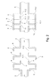
- FIG. 2 an assembly of a resonator is shown schematically in section. From the left you can see the feeding pipe 2; the lid 7 to be fastened thereon; two funnel-like pipe sections 6 and an integrally formed with the laxative pipe 5 further funnel-like pipe section. It can clearly be seen that the wall heights of the widened region 3 of the funnel-like pipe sections 6 are longer than those of the non-widened region, which then form the slot-shaped openings 11, via which a pressure exchange between the pipeline and the respective surrounding chamber 10 is possible.
- the necessary connections 20 for this embodiment are shown in the schematic diagram.
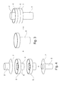
- Fig. 3 are individual parts for the preparation of a resonator and the assembled resonator shown in perspective.
- the lid 7 is mounted on a feeding pipe 2 and is placed on a funnel-like pipe section 6 which is placed on the next funnel-like pipe section 6 so that the edge of the region of larger diameter 3 on the end of the region of larger diameter of the subsequent funnel-like pipe section. 6 comes to rest and there both can be connected.
- As the last pipe section here follows a laxative pipe 5 with integrally formed funnel-like section, but it is also possible to form this last pipe section in several parts - eg, by a funnel-like pipe section 6, which is connected to a non-extended laxative pipe 5.
- resonators with a plurality of chambers of different volumes according to a modular system, as in 3 and 4 shown by way of example, which can then cancel out several resonance frequencies.
- the volumes are determined by the easily adjustable via separation lengths of the otherwise same funnel-shaped pipe sections.
- connection technique depends heavily on the material used, the medium to be damped and the dimensions of the damper.
- connection technology for the resonator components any technique that is customary in the technical field is suitable - in the case of metal pipes, for example, welding of any type, folding, soldering or gluing is suitable.
- welding of any type, folding, soldering or gluing is suitable.
- a short connection tube piece for an incoming or outgoing line can be provided on the chamber resonator according to the invention.
Landscapes
- Engineering & Computer Science (AREA)
- Physics & Mathematics (AREA)
- General Engineering & Computer Science (AREA)
- Chemical & Material Sciences (AREA)
- Aviation & Aerospace Engineering (AREA)
- Combustion & Propulsion (AREA)
- Fluid Mechanics (AREA)
- Acoustics & Sound (AREA)
- Multimedia (AREA)
- Mechanical Engineering (AREA)
- Pipe Accessories (AREA)
- Exhaust Silencers (AREA)
Applications Claiming Priority (1)
| Application Number | Priority Date | Filing Date | Title |
|---|---|---|---|
| DE202011052317U DE202011052317U1 (de) | 2011-12-15 | 2011-12-15 | Kammer-Resonator zur Dämpfung von Geräuschen und Einzeltönen in Rohrleitungen |
Publications (2)
| Publication Number | Publication Date |
|---|---|
| EP2604902A2 true EP2604902A2 (fr) | 2013-06-19 |
| EP2604902A3 EP2604902A3 (fr) | 2017-04-12 |
Family
ID=46875413
Family Applications (1)
| Application Number | Title | Priority Date | Filing Date |
|---|---|---|---|
| EP12190688.7A Withdrawn EP2604902A3 (fr) | 2011-12-15 | 2012-10-30 | Résonateur de chambre pour amortissement de bruits et sons purs dans les conduites |
Country Status (2)
| Country | Link |
|---|---|
| EP (1) | EP2604902A3 (fr) |
| DE (1) | DE202011052317U1 (fr) |
Families Citing this family (2)
| Publication number | Priority date | Publication date | Assignee | Title |
|---|---|---|---|---|
| WO2020112450A1 (fr) | 2018-11-27 | 2020-06-04 | Smith & Burgess Process Safety Consulting | Résonateur pour un système de fluide sous pression |
| DE102022212686A1 (de) * | 2022-11-28 | 2024-05-29 | Fraunhofer-Gesellschaft zur Förderung der angewandten Forschung eingetragener Verein | Rohrschalldämpfer sowie Bausatz und Verfahren zu seiner Herstellung |
Family Cites Families (4)
| Publication number | Priority date | Publication date | Assignee | Title |
|---|---|---|---|---|
| FR48791E (fr) * | 1937-09-16 | 1938-06-23 | Silencieux pour moteur à explosion ou à combustion | |
| US6116375A (en) * | 1995-11-16 | 2000-09-12 | Lorch; Frederick A. | Acoustic resonator |
| FR2912201A1 (fr) * | 2007-02-02 | 2008-08-08 | Trelleborg Fluid & Acoustic Solutions Tfas | Dispositif d'attenuation des bruits pour circuit d'admission de fluide gazeux |
| DE102009058843A1 (de) * | 2009-12-18 | 2011-06-22 | Elb Form Gmbh | Kammer-Resonator und Verfahren zu seiner Herstellung |
-
2011
- 2011-12-15 DE DE202011052317U patent/DE202011052317U1/de not_active Expired - Lifetime
-
2012
- 2012-10-30 EP EP12190688.7A patent/EP2604902A3/fr not_active Withdrawn
Non-Patent Citations (1)
| Title |
|---|
| SCHMIDT, HELMUT: "Schalltechnisches Taschenbuch", 1989 |
Also Published As
| Publication number | Publication date |
|---|---|
| EP2604902A3 (fr) | 2017-04-12 |
| DE202011052317U1 (de) | 2012-08-21 |
Similar Documents
| Publication | Publication Date | Title |
|---|---|---|
| EP2549108B1 (fr) | Amortissement du bruit dans un circuit de refroidissement | |
| DE102010028089B4 (de) | Rohrschalldämpfer für eine Strömungsmaschine und Verfahren zum Einbau eines Rohrschalldämpfers | |
| EP3728824B1 (fr) | Amortisseur à bande large pour un moteur de véhicule automobile | |
| EP1959106B2 (fr) | Silencieux pour un système d'échappement | |
| EP1715189A1 (fr) | Silencieux développé pour et destiné à un compresseur | |
| DE112015000105B4 (de) | Absorptionseinrichtung und Verfahren zu deren Herstellung | |
| DE19956172B4 (de) | Doppelkammerdämpfer | |
| EP0990851B1 (fr) | Chambre de combustion pour une turbine à gaz | |
| DE4121525A1 (de) | Schalldaempfer mit einstueckigem gehaeuse | |
| EP0713046B1 (fr) | Dispositif de silencieux pour tuyaux | |
| DE102021113611A1 (de) | Schallminderer, Verfahren zu dessen Herstellung und Fluidleitungssystem mit einem solchen Schallminderer | |
| DE2131410A1 (de) | Schalldaempfer | |
| DE102008057882A1 (de) | Karosserieteil für ein Kraftfahrzeug | |
| DE2908506A1 (de) | Schalldaempfer fuer verbrennungskraftmaschinen | |
| EP2341499A1 (fr) | Enceinte résonante et son procédé de fabrication | |
| DE202011052317U1 (de) | Kammer-Resonator zur Dämpfung von Geräuschen und Einzeltönen in Rohrleitungen | |
| EP1375848B1 (fr) | Dispositif permettant de réduire les émissions sonores et méthode pour la réalisation d'un tel dispositif | |
| EP1715188A1 (fr) | Silencieux développé pour et destiné à un compresseur | |
| DE202007003923U1 (de) | Resonator zur Dämpfung von Geräuschen und Einzeltönen in Rohrleitungen | |
| DE2738601C2 (de) | Schalldämpfer | |
| EP1510668B1 (fr) | Silencieux et dispositif d'échappement | |
| EP3529131B1 (fr) | Élément d'absorption d'énergie pour un châssis d'un véhicule automobile en tant que volume de résonance et véhicule automobile | |
| DE10339811B4 (de) | Resonator zur Reduzierung von Luftschall | |
| DE2231617A1 (de) | Schalldaempfer fuer drucklufthaemmer | |
| DE1292666B (de) | Schalldaempfendes Gasleitrohr |
Legal Events
| Date | Code | Title | Description |
|---|---|---|---|
| PUAI | Public reference made under article 153(3) epc to a published international application that has entered the european phase |
Free format text: ORIGINAL CODE: 0009012 |
|
| AK | Designated contracting states |
Kind code of ref document: A2 Designated state(s): AL AT BE BG CH CY CZ DE DK EE ES FI FR GB GR HR HU IE IS IT LI LT LU LV MC MK MT NL NO PL PT RO RS SE SI SK SM TR |
|
| AX | Request for extension of the european patent |
Extension state: BA ME |
|
| PUAL | Search report despatched |
Free format text: ORIGINAL CODE: 0009013 |
|
| AK | Designated contracting states |
Kind code of ref document: A3 Designated state(s): AL AT BE BG CH CY CZ DE DK EE ES FI FR GB GR HR HU IE IS IT LI LT LU LV MC MK MT NL NO PL PT RO RS SE SI SK SM TR |
|
| AX | Request for extension of the european patent |
Extension state: BA ME |
|
| RIC1 | Information provided on ipc code assigned before grant |
Ipc: F16L 55/033 20060101AFI20170306BHEP Ipc: G10K 11/172 20060101ALN20170306BHEP Ipc: G10K 11/16 20060101ALI20170306BHEP |
|
| STAA | Information on the status of an ep patent application or granted ep patent |
Free format text: STATUS: THE APPLICATION IS DEEMED TO BE WITHDRAWN |
|
| 18D | Application deemed to be withdrawn |
Effective date: 20171013 |