EP2604896A1 - Mischvorrichtung für Leitungswasser - Google Patents
Mischvorrichtung für Leitungswasser Download PDFInfo
- Publication number
- EP2604896A1 EP2604896A1 EP20110193649 EP11193649A EP2604896A1 EP 2604896 A1 EP2604896 A1 EP 2604896A1 EP 20110193649 EP20110193649 EP 20110193649 EP 11193649 A EP11193649 A EP 11193649A EP 2604896 A1 EP2604896 A1 EP 2604896A1
- Authority
- EP
- European Patent Office
- Prior art keywords
- flow
- valve
- mixing
- spindle
- water
- Prior art date
- Legal status (The legal status is an assumption and is not a legal conclusion. Google has not performed a legal analysis and makes no representation as to the accuracy of the status listed.)
- Granted
Links
- 238000002156 mixing Methods 0.000 title claims abstract description 48
- 239000008399 tap water Substances 0.000 title claims description 4
- 235000020679 tap water Nutrition 0.000 title claims description 4
- XLYOFNOQVPJJNP-UHFFFAOYSA-N water Substances O XLYOFNOQVPJJNP-UHFFFAOYSA-N 0.000 claims abstract description 58
- 230000001105 regulatory effect Effects 0.000 claims description 9
- 238000000034 method Methods 0.000 claims description 2
- 238000000265 homogenisation Methods 0.000 abstract description 3
- 230000001747 exhibiting effect Effects 0.000 abstract description 2
- 239000010865 sewage Substances 0.000 abstract 1
- 125000006850 spacer group Chemical group 0.000 abstract 1
- 238000011161 development Methods 0.000 description 5
- 230000018109 developmental process Effects 0.000 description 5
- 230000015572 biosynthetic process Effects 0.000 description 3
- 238000005192 partition Methods 0.000 description 2
- 229910001369 Brass Inorganic materials 0.000 description 1
- 238000009529 body temperature measurement Methods 0.000 description 1
- 239000010951 brass Substances 0.000 description 1
- 230000000694 effects Effects 0.000 description 1
- 238000003780 insertion Methods 0.000 description 1
- 230000037431 insertion Effects 0.000 description 1
- 230000001788 irregular Effects 0.000 description 1
- 238000004519 manufacturing process Methods 0.000 description 1
- 238000005259 measurement Methods 0.000 description 1
- 239000002184 metal Substances 0.000 description 1
- 230000035515 penetration Effects 0.000 description 1
- 239000007787 solid Substances 0.000 description 1
- 238000011144 upstream manufacturing Methods 0.000 description 1
Images





Classifications
-
- F—MECHANICAL ENGINEERING; LIGHTING; HEATING; WEAPONS; BLASTING
- F16—ENGINEERING ELEMENTS AND UNITS; GENERAL MEASURES FOR PRODUCING AND MAINTAINING EFFECTIVE FUNCTIONING OF MACHINES OR INSTALLATIONS; THERMAL INSULATION IN GENERAL
- F16K—VALVES; TAPS; COCKS; ACTUATING-FLOATS; DEVICES FOR VENTING OR AERATING
- F16K19/00—Arrangements of valves and flow lines specially adapted for mixing fluids
- F16K19/006—Specially adapted for faucets
-
- F—MECHANICAL ENGINEERING; LIGHTING; HEATING; WEAPONS; BLASTING
- F16—ENGINEERING ELEMENTS AND UNITS; GENERAL MEASURES FOR PRODUCING AND MAINTAINING EFFECTIVE FUNCTIONING OF MACHINES OR INSTALLATIONS; THERMAL INSULATION IN GENERAL
- F16K—VALVES; TAPS; COCKS; ACTUATING-FLOATS; DEVICES FOR VENTING OR AERATING
- F16K11/00—Multiple-way valves, e.g. mixing valves; Pipe fittings incorporating such valves
- F16K11/02—Multiple-way valves, e.g. mixing valves; Pipe fittings incorporating such valves with all movable sealing faces moving as one unit
- F16K11/06—Multiple-way valves, e.g. mixing valves; Pipe fittings incorporating such valves with all movable sealing faces moving as one unit comprising only sliding valves, i.e. sliding closure elements
- F16K11/072—Multiple-way valves, e.g. mixing valves; Pipe fittings incorporating such valves with all movable sealing faces moving as one unit comprising only sliding valves, i.e. sliding closure elements with pivoted closure members
- F16K11/074—Multiple-way valves, e.g. mixing valves; Pipe fittings incorporating such valves with all movable sealing faces moving as one unit comprising only sliding valves, i.e. sliding closure elements with pivoted closure members with flat sealing faces
-
- F—MECHANICAL ENGINEERING; LIGHTING; HEATING; WEAPONS; BLASTING
- F16—ENGINEERING ELEMENTS AND UNITS; GENERAL MEASURES FOR PRODUCING AND MAINTAINING EFFECTIVE FUNCTIONING OF MACHINES OR INSTALLATIONS; THERMAL INSULATION IN GENERAL
- F16K—VALVES; TAPS; COCKS; ACTUATING-FLOATS; DEVICES FOR VENTING OR AERATING
- F16K31/00—Actuating devices; Operating means; Releasing devices
- F16K31/02—Actuating devices; Operating means; Releasing devices electric; magnetic
- F16K31/04—Actuating devices; Operating means; Releasing devices electric; magnetic using a motor
- F16K31/041—Actuating devices; Operating means; Releasing devices electric; magnetic using a motor for rotating valves
-
- F—MECHANICAL ENGINEERING; LIGHTING; HEATING; WEAPONS; BLASTING
- F16—ENGINEERING ELEMENTS AND UNITS; GENERAL MEASURES FOR PRODUCING AND MAINTAINING EFFECTIVE FUNCTIONING OF MACHINES OR INSTALLATIONS; THERMAL INSULATION IN GENERAL
- F16K—VALVES; TAPS; COCKS; ACTUATING-FLOATS; DEVICES FOR VENTING OR AERATING
- F16K37/00—Special means in or on valves or other cut-off apparatus for indicating or recording operation thereof, or for enabling an alarm to be given
- F16K37/0025—Electrical or magnetic means
-
- G—PHYSICS
- G05—CONTROLLING; REGULATING
- G05D—SYSTEMS FOR CONTROLLING OR REGULATING NON-ELECTRIC VARIABLES
- G05D23/00—Control of temperature
- G05D23/01—Control of temperature without auxiliary power
- G05D23/13—Control of temperature without auxiliary power by varying the mixing ratio of two fluids having different temperatures
- G05D23/1393—Control of temperature without auxiliary power by varying the mixing ratio of two fluids having different temperatures characterised by the use of electric means
Definitions
- the invention relates to a mixing device for tap water according to the preamble of patent claim 1.
- thermocouple When supplying water, especially in the kitchen and bathroom, there is regularly the requirement to be able to set a defined water temperature and a defined water pressure.
- a thermostatic mixer which regulates the mixing ratio of a cold water flow and a hot water flow via a thermal element.
- the thermocouple is arranged such that due to the thermal expansion of the element, the water flows are influenced.
- the relative position of the thermocouple can be varied via a knob, whereby the desired water temperature is adjustable.
- the adjustment of the water pressure via a downstream flow control valve, with which the inflow of the mixed water flow of the thermostatic valve is adjustable. The adjustment is made regularly by turning or tilting devices.
- the previously known mixing device largely ensures a predetermined flow rate and temperature of the water flow rate on the basis of the respective measured values.
- a predetermined flow rate and temperature of the water flow rate on the basis of the respective measured values.
- considerable temperature fluctuations can result.
- the desired temperature reliably adjusts to the predetermined setpoint values.
- the invention aims to remedy this situation.
- the invention has for its object to provide a mixing device of the aforementioned type, in particular at the beginning of a water passage, a predetermined temperature of the water flow is ensured. According to the invention, this object is solved by the features of the characterizing part of patent claim 1.
- a mixing device of the aforementioned type is provided, in particular at the beginning of a water passage, a predetermined temperature of the water flow rate is ensured. It has been shown that a homogenization of the mixed water flow flowing around the temperature sensor allows a reliable measurement and thus also a reliable temperature control of the water flow rate.
- the means for homogenizing the mixed water flow flowing around the temperature sensor comprise a swirling device which is arranged in the inflow of the quantity valve.
- the swirling device is formed by a wellgelradular.
- the temperature sensor is arranged in the spindle of the multi-way valve. As a result, an optimal positioning of the sensor is achieved in the flow of water flow within the flow control valve.
- the means for homogenizing the mixing water flow flowing around the temperature sensor are formed by the spreader disk of the quantity valve, which is designed such that it has exactly one inlet opening.
- control disk is formed as a circular disk, on which a circular arc-shaped web is formed, which encloses an inner space by at least 250 °, preferably by 270 °, whereby an arcuate inlet opening is formed.
- a one-sided mixing water flow is ensured. Due to the at least 110 ° large, circular arc inlet opening and an inflow of parts of both windows is possible.
- a rotation radius of the spindle of 180 ° is made possible, whereby an embodiment of the multi-way valve is such that both the assignment of the process to be supplied and the flow rate of the water flow rate can be adjusted via the spindle.
- an outlet opening is introduced into the circular disk of the inlet opening opposite. This ensures leakage of the flow of water after passing through the temperature sensor.
- a flow sensor for measuring the flow of water flow is arranged in the line, which is connected to the control and regulating device, wherein via the control and regulating device, the flow rate the amount of water flow is adjustable. This allows a comfortable control of water flow rate and temperature.
- both the mixing valve and the quantity valve have a head piece, which is centrally penetrated by a radially guided in this spindle and in the laterally opposite two windows are introduced and receives on its opposite side of the spindle a passage disc with two openings , wherein the flow direction of the water flow in the flow control valve is opposite to the flow direction in the mixing valve.
- the mixing device 1 chosen as an exemplary embodiment comprises a rail 11, on which two housing parts 12 are arranged side by side, which are connected to one another via a line 13, in which a flow sensor 21 is arranged.
- the one, inlet-side housing part 12 receives a mixing valve upper part 3 and is provided with two connecting pieces 121, 122.
- the other, drain-side housing part 12 receives a Mehrwegeventiloberteil 4 and is also provided with two connecting pieces 121, 122, Furthermore, two electric motors 5, 6 for actuating the mixing valve upper part 3 and der Mehrwegventiloberteils 4 anabend.
- the rail 11 is formed in the embodiment as a rectangular metal sheet, which is angled perpendicularly at one longitudinal side.
- bores for fixing the two housing parts 12 are introduced.
- two recesses 111 for the passage of a valve upper part 3, 4 are introduced.
- bores 112 for fastening the device 1 are provided in the angled region of the rail 11.
- the housing parts 12 are identical and formed in the embodiment as a substantially cylindrical brass hollow body. On its underside facing away from the rail 11, two bores 120 for receiving the connecting pieces 121, 122 are introduced into the housing 12.
- the holes 120 are formed drop-shaped and have about one-third of their length a diameter constriction through which a shoulder 127 is formed.
- the two bores 120 of the housing part 12 have a common partition 128 into which the two connection parts 121, 122 tangentially a guide 129 is introduced for receiving a locking pin.
- the guide 129 is in the embodiment executed in the form of a hollow cylindrical bore, which is provided at its outer end with a - not shown - internal thread. By the guide 129 forming hole, the common partition 128 is severed, so that an inserted into the guide 129 locking pin projects into the two holes 120.
- a bore 126 is introduced into the housing part 12, which opens into the bore 123 serving as a valve seat.
- a shoulder 1261 is formed, which serves as a stop for the line 13.
- the connecting pieces 121, 122 are designed in the manner of a pipe section and serve to connect inlet and outlet lines to the housing parts 12.
- the connecting piece 121 is designed as a short connecting piece and has circumferentially a circumferential locking groove 1211 with a circular arc-shaped cross-section.
- the diameter of the circular arc-shaped cross section of the locking groove 1211 corresponds substantially to the outer diameter of a introduced into the guide 129 locking pin.
- On both sides of the locking groove 1211 in the connecting piece 121 circumferentially continue two grooves 1212 for receiving an O-ring 1213 is introduced.
- the connecting piece 122 which is designed to be longer in relation to the connecting piece 121, likewise has a locking groove 1221, on both sides of which, circumferentially, two grooves 1222 for receiving an O-ring 1223 are inserted.
- the mixing valve upper part 3 chosen as an exemplary embodiment has a head piece 31, which is penetrated centrally by a spindle 32 guided radially in it. With the spindle 32, a control disk 33 is positively connected and guided radially in the head piece 31. On the side facing away from the spindle 32 of the control disk 33, an inlet disk 34 is provided in the head piece 31, to which a connection plate 35 connects, which comes to rest with the valve seat formed by the bore 123 of the housing part 12.
- the head piece 31 consists of a symmetrical hollow body whose two end faces are open. On its side facing the housing part 12, the head piece 31 has a sleeve-like part 310. In part 310, two passage windows 311 are provided.
- a collar 312 of the head piece 31 After insertion into the housing part 12 is a collar 312 of the head piece 31 on the bottom of serving as a valve seat bore 123.
- a back turn 313 is arranged inside in the region of the collar 312.
- the spindle 32 is substantially solid. It is executed on its side facing away from the head piece 31 end outside as contemplatvielkant 321. Subsequently, a cylindrical surface 322 is provided externally on the spindle 32, with which the spindle 32 is guided radially in the head piece 31. Between the cylindrical surface 322 and the outer polyhedron 321 a recess 323 is provided, in which a shaft lock 326 is resiliently inserted in the form of a snap ring. The shaft lock 326 prevents the penetration of the spindle 32 in the head piece 31 beyond the intended extent. Furthermore, in the cylindrical surface 322 two annular grooves 324 are introduced, the O-rings 325 record. On the outer polygon 321 opposite side of the spindle 32, a disc 327 is formed, which has on its the housing part 12 side facing a driver 3271.
- the control disk 33 is formed substantially as a circular disk, from which a circular cutout 331 is excluded.
- the circular cutout 331 has an angle of approximately 90 ° in the exemplary embodiment.
- the control disk 3 On its side facing the spindle 32, the control disk 3 has two diametrically arranged arcuate shoulders 332.
- the annular shoulder 332 comprises in the assembled state the driver 3271 of the spindle 32.
- Recesses 333 are formed on the shoulders 332, into which the driver 3271 grasps (cf. FIG. 4c) ).
- the inlet disc is in FIG. 5 shown. It has on its circumference two diametrically opposite lugs 341. With the lugs 341, the disc 34 in recesses, which are provided for this purpose in the sleeve-shaped part 310 of the head piece 31.
- the inlet disk 34 is thus non-rotatably arranged in the head piece 31.
- the inlet disk 34 has two adjacent circular cutouts 342, which correspond to the circular cutout 331 of the control disk 33.
- web-like contours 343 are integrally formed.
- connection plate 35 is made in the embodiment of plastic. It also has on its circumference two diametrically opposite lugs with which it engages in recesses provided for this purpose in the sleeve-shaped part 310 of the head piece 31. It is thus non-rotatably arranged in the head piece 31.
- the connecting plate 35 has two juxtaposed passage openings 351, which are positioned with the two circular cutouts 342 of the inlet disc 34 in overlap and in each of which a lip seal 352 is arranged to seal against the valve seat formed by the bore 123 of the housing part 12. Furthermore, the connection plate 35 has on its underside facing away from the inlet disk 34 a cylindrical pin 353 which corresponds to a blind hole arranged in the housing part 12 and serves to position the mixing valve upper part 3 in the housing part 12.
- the multi-way valve upper part 4 is constructed substantially identical to the mixing valve upper part 3. It has an identical head piece 41, which is penetrated centrally by a spindle 42 guided radially in it.
- a thermal sensor 22 for continuously measuring the temperature of the water supplied from the mixing valve upper part 3 is additionally arranged (cf. FIG. 6 ).
- the spindle 42 is also a, albeit differently designed control disk 43 positively connected and guided radially in the head piece 41.
- an inlet disc 44 is provided in the header 41, to which a connection plate 45 connects, which comes with the valve seat formed by the bore 123 of the housing part 12 to the plant.
- the multi-way valve 4 differs from the mixing valve 3 by the different control disk 43, inlet disk 44 and connecting disk 45 used.
- the control disk 43 is designed substantially as a circular disk, from which a circular cutout 431 is excluded.
- the circular cutout 431 has an angle of approximately 90 ° in the exemplary embodiment.
- the control disk 43 On its side facing the spindle 42, in contrast to the control disk 33 of the mixing valve upper part 3, the control disk 43 has a circular-arc-shaped web 432 which encloses an inner space of 270 °. This forms an arcuate inlet opening 4321.
- the circular-arc-shaped web 432 comprises the driver 3271 of the spindle 42.
- Recesses 433 are formed on the web 432 in the opposite direction, in which the driver 3271 grasps (cf. Fig. 8 c )).
- the inlet port 4321 is disposed opposite to the circular cutout 431.
- the inlet disk 44 of the multiway valve upper part 4 is in FIG. 9 shown.
- it has two circular passage openings 442 arranged diametrically opposite one another.
- web-shaped contours 442 are integrally formed around the passage openings 442 and in the area of the laterally formed lugs 441 on the underside of the inlet disk 44 facing the connection disk 45.
- the connecting disk 45 has two circular passage openings 451 arranged diametrically opposite one another, which are aligned with the passage openings 442 of the inlet disk 44.
- a web 452 is integrally formed on the inside for receiving a lip seal 453.
- the lip seal 453 is held in the passage opening 451 via an inserted support ring 454.
- the lips 4531 of the lip seal 453 seal against the inlet disc 44 and against the bottom of the valve seat Bore 123 of the housing part 12 at.
- the connection plate 45 has a cylindrical pin 455 on its underside facing away from the inlet disk 44, which corresponds to a blind bore introduced into the housing part 12 and serves to position the multiway valve upper part 4 in the housing part 12.
- the housing parts 12 are fastened to the rail 11 by means of screws (not shown) in such a way that the valve upper part 3, 4 introduced into the respective housing part 12 protrudes with its head piece 31, 41 through the recess 111 of the rail 11.
- the housing parts 12 are connected to each other via the line 13, which bears with one end on the shoulder 1261 of a housing part 12.
- an impeller 7 is arranged within the conduit 13 upstream of the multiway valve upper part 4.
- the impeller 7 essentially consists of a circular disk-shaped main body 71, in which four quarter-circular recesses 72 are introduced radially uniformly spaced from each other.
- the recesses 72 centered covering the main body 71 propeller-like wings 73 are formed (see. Fig. 13 ).
- the thus formed impeller 7 is positioned in the conduit 13 so that it is set in flow in the direction of the multi-way valve upper part 4 in rotation, whereby a thorough mixing of the water flow rate is effected.
- an electric motor 5, 6 is arranged on each housing part 12, which is connected by means - not shown - screws, which are guided by elongated holes of the rail 11 with the rail 11, such that the motor shaft 51st , 61 of the respective motor 5, 6 protrudes through the recess 111 of the rail 11.
- the shafts 51, 61 of the motors 5, 6 connected to a toothed disc 52, 62, which via a toothed belt 36, 46 with the outer polygon of the spindle 32, 42 of the valve body parts 3, 4 is connected.
- a rotation of the shaft 51, 61 of a motor is thereby transmitted to a spindle 32, 42 of a valve upper part 3, 4, which thereby can be operated.
- a - not shown - control and regulating device is the input side with the flow sensor 21 and the temperature sensor 22 connected. Furthermore, an input unit (not shown) is arranged on the input side, by means of which user-side specifications with respect to the water temperature, the water flow rate and the water drainage (bathtub / shower) are adjustable. On the output side is - not shown - control and regulating electronically connected to the motors 5, 6.
- the mixing device is connected on the inlet side via the connecting piece 121 with a cold water inlet and via the connecting piece 122 with a hot water inlet.
- the drain-side housing part is connected via the connecting piece 121 with a faucet of a bathtub and via the connecting piece 122 with the inlet of a shower head.
- the valve heads 3, 4 are adjusted via the motors 5, 6 such that the measured values transmitted via the sensors 21, 22 coincide with the selected default data ,
- the desired water temperature is set via the mixing valve upper part 3, which is continuously measured in the inlet of the multi-way valve upper part 4 via the sensor 22.
- the sensor 22 is flushed with the vortexed and homogenized via the impeller 7 water flow. Due to the particular configuration of the control disk 43 with only one inlet opening 4321, countercurrent formation is avoided. On the one hand, the assignment of the water flow provided by the mixing valve upper part 3 to the bath or shower takes place via the multiway valve upper part 4; On the other hand, the multi-way valve upper part 4 can be adjusted by adjusting the coverage of the circular cutout 431 of the control disk 43 with the passage opening 442 of the inlet disk 44 or with this corresponding passage opening 451 of the connection disk 45.
- the water flow rate achieved in each case is reported via the flow sensor 21 to the control and regulating device (not shown), which performs a readjustment of the multiway valve upper part 4 via the motor 6 in the event of a deviation from the set default value.
- a readjustment of the Mixing valve upper part 3 via the motor 5 in case of deviations between the measured by the temperature sensor 22 real value to the preset temperature setpoint.
Landscapes
- Engineering & Computer Science (AREA)
- General Engineering & Computer Science (AREA)
- Mechanical Engineering (AREA)
- Physics & Mathematics (AREA)
- General Physics & Mathematics (AREA)
- Automation & Control Theory (AREA)
- Multiple-Way Valves (AREA)
Abstract
Description
- Die Erfindung betrifft eine Mischvorrichtung für Leitungswasser nach dem Oberbegriff des Patentanspruchs 1.
- Bei der Zuführung von Wasser, insbesondere in Küche und Bad, besteht regelmäßig die Anforderung, eine definierte Wassertemperatur sowie einen definierten Wasserdruck einstellen zu können. Zur Einstellung der Temperatur ist es bekannt, Thermostatmischer einzusetzen, welche über ein thermisches Element das Mischungsverhältnis eines Kaltwasserstroms sowie eines Warmwasserstroms regelt. Das Thermoelement ist dabei derart angeordnet, dass bedingt durch die thermische Ausdehnung des Elementes die Wasserströme beeinflusst werden. Die relative Position des Thermoelements kann über einen Einstellknopf variiert werden, wodurch die gewünschte Wassertemperatur einstellbar ist. Die Einstellung des Wasserdrucks erfolgt über ein nachgeschaltetes Mengenventil, mit dem der Zufluss des Mischwasserstroms des Thermostatventils einstellbar ist. Die Einstellung erfolge regelmäßig über Dreh- oder Kippeinrichtungen. Durch mechanische Einwirkungen, wie durch den Wasserdurchfluss indizierte Vibrationen oder durch den Verstellhebel anliegende Gewichtskräfte ist jedoch oftmals eine eigendynamische Verstellung bewirkt, welche eine Änderung der tatsächlich anliegenden Temperatur bzw. des tatsächliche anliegenden Wasserdrucks zu Folge hat und die ein Nachstellen der Parameter in unregelmäßigen Zeitabständen erforderlich machen kann.
- Vor diesem Hintergrund besteht zunehmend die Anforderung, die Temperatur und den Volumenstrom des Wassers komfortabel und zuverlässig einstellen zu können. Aus der
DE 20 2009 000 525 U1 ist eine elektronisch regelbare Mischvorrichtung für Leitungswasser bekannt, welche eine komfortable Regelung von Wasserdruck und -temperatur ermöglicht. Dabei sind ein Mischventil und Mengenventil über eine Leitung miteinander verbunden hintereinander geschaltet angeordnet. Das Mengenventil weist ein seitlich gegenüberliegend zwei Fenster aufweisendes Kopfstück auf, das von einer in diesem radial geführten Spindel mittig durchsetzt ist, die mit einer Steuerscheibe im Eingriff steht. Zur Ermittlung der Temperatur des über das Mischventil zugeleiteten Wassermengenstroms ist ein Temperatursensor angeordnet, der mit der Steuer- und Regelvorrichtung verbunden ist, über welche die Temperatur des Wassermengenstroms einstellbar ist. - Die vorbekannte Mischvorrichtung gewährleistet in weiten Teilen eine vorgegebene Durchflussmenge und Temperatur des Wassermengenstroms auf Basis der jeweils vorliegenden Messwerte. Es hat sich jedoch gezeigt, dass insbesondere zu Beginn des Wasserdurchlaufs sich erhebliche Temperaturschwankungen ergeben können, Im weiteren Verlauf des Durchflusses stellt sich die gewünschte Temperatur zuverlässig auf die vorgegebenen Sollwerte ein.
- Hier will die Erfindung Abhilfe schaffen. Der Erfindung liegt die Aufgabe zugrunde, eine Mischvorrichtung der vorgenannten Art zu schaffen, bei der insbesondere auch zu Beginn eines Wasserdurchlaufs eine vorgegebene Temperatur des Wassermengenstroms gewährleistet ist. Gemäß der Erfindung wird diese Aufgabe durch die Merkmale des kennzeichnenden Teils des Patentanspruchs 1 gelöst.
- Mit der Erfindung ist eine Mischvorrichtung der vorgenannten Art geschaffen, bei der insbesondere auch zu Beginn eines Wasserdurchlaufs eine vorgegebene Temperatur des Wassermengenstroms gewährleistet ist. Es hat sich gezeigt, dass eine Homogenisierung des den Temperatursensor umströmenden Mischwasserstroms eine zuverlässige Messung und damit auch eine zuverlässige Temperierung des Wassermengenstroms ermöglicht.
- In Weiterbildung der Erfindung umfassen die Mittel zur Homogenisierung des den Temperatursensor umströmenden Mischwasserstroms eine Verwirbeleinrichtung, die im Zustrom des Mengenventils angeordnet ist. Hierdurch werden die von dem Mischventil herströmenden Kalt- und Warmwasserströme vermengt, wodurch eine gute Homogenisierung bewirkt ist. Bevorzugt ist die Verwirbeleinrichtung durch eine Flügelradscheibe gebildet.
- In Ausgestaltung der Erfindung ist der Temperatursensor in der Spindel des Mehrwegeventils angeordnet. Hierdurch ist eine optimale Positionierung des Sensors in dem Wassermengenstrom innerhalb des Mengenventils erzielt.
- In weiterer Ausgestaltung der Erfindung sind die Mittel zur Homogenisierung des den Temperatursensor umströmenden Mischwasserstroms durch die Streuerscheibe des Mengenventils gebildet, die derart ausgebildet ist, dass sie genau eine Einströmöffnung aufweist. Hierdurch ist eine Gegenstrombildung verhindert, welche durch gleichzeitiges Einlaufen von Mischwasser durch die gegenüberliegend angeordneten Fenster des Kopfstücks entstehen kann. Hierdurch ist die Bildung von Lufteinschlüssen vermieden, wodurch eine zuverlässige Temperaturmessung gewährleistet ist.
- In Weiterbildung der Erfindung ist die Steuerscheibe als kreisrunde Scheibe ausgebildet, auf der ein kreisbogenförmiger Steg angeformt ist, der einen inneren Raum um wenigstens 250°, bevorzugt um 270° umschließt, wodurch eine kreisbogenförmige Einlassöffnung gebildet ist. Hierdurch ist ein einseitiger Mischwasserzustrom gewährleitstet. Durch die wenigstens 110° große, kreisbogenförmige Einlassöffnung wird auch ein Zufluss von Teilen beider Fenster ermöglicht. Hierdurch ist ein Rotationsradius der Spindel von 180° ermöglicht, wodurch eine Ausbildung des Mehrwegeventils derart ermöglicht ist, dass über die Spindel sowohl die Zuordnung des zu versorgenden Ablaufs als auch die Durchflussmenge des Wassermengenstroms einstellbar ist.
- In Weiterbildung der Erfindung ist in die kreisrunde Scheibe der Einlassöffnung gegenüberliegend eine Auslassöffnung eingebracht. Hierdurch ist ein Austreten des Wassermengenstroms nach Passieren des Temperatursensors gewährleistet.
- In weiterer Ausgestaltung der Erfindung ist in der Leitung ein Durchflusssensor zur Messung des Wassermengenstroms angeordnet, der mit der Steuer- und Regelvorrichtung verbunden ist, wobei über die Steuer- und Regelvorrichtung die Durchflussmenge des Wassermengenstroms einstellbar ist. Hierdurch ist eine komfortable Regelung von Wassermengenstrom und -temperatur ermöglicht.
- In Weiterbildung der Erfindung weisen sowohl das Mischventil als auch das Mengenventil ein Kopfstück auf, das von einer in diesem radial geführten Spindel mittig durchsetzt ist und in das seitlich gegenüberliegend zwei Fenster eingebracht sind und das auf seiner der Spindel entgegengesetzten Seite eine Durchlassscheibe mit zwei Durchtrittsöffnungen aufnimmt, wobei die Durchflussrichtung des Wasserstromes in dem Mengenventil entgegensetzt der Durchflussrichtung im Mischventil ist. Hierdurch ist die parallele Anordnung von Zufluss- und Abflussleitungen ermöglicht. Weiterhin können hierdurch weitgehend identische Ventiloberteile zum Einsatz kommen, wodurch Fertigungs- und Lagerkosten reduziert sind.
- Andere Ausgestaltungen und Weiterbildungen der Erfindung sind in den übrigen Unteransprüchen angegeben. Ein Ausführungsbeispiel der Erfindung ist in der Zeichnung dargestellt und wird nachfolgend im Einzelnen beschrieben. Es zeigen:
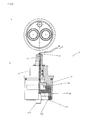
- Fig. 1
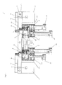
- die Ansicht einer Mischvorrichtung im Teilschnitt;
- Fig. 3
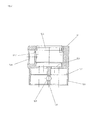
- die Darstellung des ablaufseitigen Gehäuseteils der Mischvorrichtung aus
Figur 1 in Schnittdarstellung; - Fig. 3
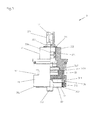
- die Darstellung des Mischventiloberteils der Vorrichtung aus
Figur 1 im Teilschnitt; - Fig. 4
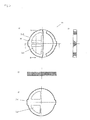
- die Darstellung der Steuerscheibe des Mischventiloberteils aus
Figur 3 ;- a) in der Ansicht von unten;
- b) im Axialschnitt;
- c) in der Draufsicht;
- Fig. 5
- die Darstellung der Einlassscheibe des Mischventiloberteils aus
Figur 3 - a) in der Draufsicht;
- b) in Schnittdarstellung entlang der Linie B-B in Figur a);
- c) in Schnittdarstellung entlang der Linie C-C in Figur a);
- d) in der Ansicht von unten;
- Fig. 6
- die Darstellung des Mehrwegeventiloberteils aus
Figur 1 - a) in der Ansicht von unten;
- b) im Teilschnitt;
- Fig. 7
- die Detaildarstellung des Kopfstücks des Mehrwegeventiloberteils aus
Figur 6 - a) in der Seitenansicht;
- b) im Querschnitt;
- c) im Schnitt A-A der Darstellung b);
- Fig. 8
- die Darstellung der Steuerscheibe des Mehrwegeventiloberteils aus
Figur 6 - a) in der Ansicht von unten;
- b) im Axialschnitt;
- c) in der Draufsicht;
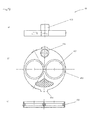
- Fig. 9
- die Darstellung der Einlassscheibe des Mehrwegeventiloberteils aus
Figur 6 - a) in der Draufsicht;
- b) im Querschnitt;
- c) in der Ansicht von unten;
- Fig. 10
- die Darstellung der Anschlussscheibe des Mehrwegeventiloberteils aus
Figur 6 - a) in der Seitenansicht;
- b) in der Draufsicht;
- c) im Querschnitt;
- Fig. 11
- die Darstellung der Lippendichtung des Mehrwegeventiloberteils aus
Figur 6 - a) im Querschnitt;
- b) in der Draufsicht;
- Fig. 12
- die Darstellung des Stützrings des Mehrwegeventiloberteils aus
Figur 6 - a) im Querschnitt;
- b) in der Draufsicht und
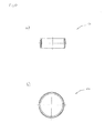
- Fig. 13
- die Darstellung eines Flügelrades
- a) in der Seitenansicht;
- b) in der Draufsicht.
- Die als Ausführungsbeispiel gewählte Mischvorrichtung 1 umfasst eine Schiene 11, an der nebeneinander zwei Gehäuseteile 12 angeordnet sind, welche über eine Leitung 13 miteinander verbunden sind, in der ein Durchflusssensor 21 angeordnet ist. Das eine, zulaufseitige Gehäuseteil 12 nimmt ein Mischventiloberteil 3 auf und ist mit zwei Anschlussstücken 121, 122 versehen. Das andere, ablaufseitige Gehäuseteil 12 nimmt ein Mehrwegeventiloberteil 4 auf und ist ebenfalls mit zwei Anschlussstücken 121, 122 versehen, Weiterhin sind zwei Elektromotoren 5, 6 zur Betätigung des Mischventiloberteils 3 bzw. des Mehrwegeventiloberteils 4 angeordnet.
- Die Schiene 11 ist im Ausführungsbeispiel als rechteckiges Metallblech ausgebildet, welches an einer Längsseite rechtwinklig abgewinkelt ist. In der Schiene 11 sind Bohrungen zur Befestigung der beiden Gehäuseteile 12 eingebracht. Weiterhin sind zwei Ausnehmungen 111 zum Durchtritt eines Ventiloberteils 3, 4 eingebracht. Zu beiden Enden der Schiene 11 ist in diese jeweils ein Langloch zum Durchtritt der Welle eines Elektromotors 5, 6 eingebracht. Weiterhin sind im abgewinkelten Bereich der Schiene 11 Bohrungen 112 zur Befestigung der Vorrichtung 1 vorgesehen.
- Die Gehäuseteile 12 sind identisch ausgebildet und im Ausführungsbeispiel als im Wesentlichen zylindrische Messinghohlkörper ausgebildet. An ihrer der Schiene 11 abgewandten Unterseite sind in das Gehäuse 12 zwei Bohrungen 120 zur Aufnahme der Anschlussstücke 121, 122 eingebracht. Die Bohrungen 120 sind tropfförmig ausgebildet und weisen auf etwa einem Drittel ihrer Länge eine Durchmesserverengung auf, durch die ein Absatz 127 gebildet ist. Die beiden Bohrungen 120 des Gehäuseteils 12 weisen eine gemeinsame Trennwand 128 auf, in welche die beiden Anschlussteile 121, 122 tangierend eine Führung 129 zur Aufnahme eines Sperrbolzens eingebracht ist. Die Führung 129 ist im Ausführungsbeispiel in Form einer hohlzylindrischen Bohrung ausgeführt, welche an ihrem äußeren Ende mit einem - nicht dargestellten - Innengewinde versehen ist. Durch die die Führung 129 bildende Bohrung ist die gemeinsame Trennwand 128 durchtrennt, sodass ein in die Führung 129 eingeführter Sperrbolzen in die beiden Bohrungen 120 hineinragt.
- Seitlich ist in das Gehäuseteil 12 eine Bohrung 126 eingebracht, welche in der als Ventilsitz dienenden Bohrung 123 mündet. In der Bohrung 126 ist ein Absatz 1261 angeformt, der als Anschlag für die Leitung 13 dient.
- Die Anschlussstücke 121, 122 sind in Art eines Rohrstücks ausgebildet und dienen dem Anschluss von Zulauf- bzw. Ablaufleitungen an den Gehäuseteilen 12. Das Anschlussstück 121 ist als kurzes Anschlussstück ausgebildet und weist endseitig umlaufend eine Sperrnut 1211 mit einem kreisbogenförmigen Querschnitt auf. Der Durchmesser des kreisbogenförmigen Querschnitts der Sperrnut 1211 entspricht dabei im Wesentlichen dem Außendurchmesser eines in die Führung 129 eingebrachten Sperrbolzens. Beidseitig der Sperrnut 1211 sind in dem Anschlussstück 121 umlaufend weiterhin zwei Nuten 1212 zur Aufnahme eines O-Rings 1213 eingebracht.
- Das gegenüber dem Anschlussstück 121 länger ausgebildete Anschlussstück 122 weist ebenfalls eine Sperrnut 1221 auf, beidseitig derer außen umlaufend zwei Nuten 1222 zur Aufnahme eines O-Rings 1223 eingebracht sind.
- Das als Ausführungsbeispiel gewählte Mischventiloberteil 3 weist ein Kopfstück 31 auf, das von einer in ihm radial geführten Spindel 32 mittig durchsetzt ist. Mit der Spindel 32 ist eine Steuerscheibe 33 formschlüssig verbunden und im Kopfstück 31 radial geführt. An dem der Spindel 32 abgewandten Seite der Steuerscheibe 33 ist eine Einlassscheibe 34 in dem Kopfstück 31 vorgesehen, an die sich eine Anschlussscheibe 35 anschließt, die mit dem durch die Bohrung 123 gebildeten Ventilsitz des Gehäuseteils 12 zur Anlage kommt.
- Das Kopfstück 31 besteht aus einem symmetrischen Hohlkörper, dessen beiden Stirnflächen offen sind. Auf seiner dem Gehäuseteil 12 zugewandten Seite weist das Kopfstück 31 einen hülsenartigen Teil 310 auf. In dem Teil 310 sind zwei Durchtrittsfenster 311 vorgesehen.
- Nach dem Einbringen in das Gehäuseteil 12 liegt ein Bund 312 des Kopfstücks 31 auf dem Grund der als Ventilsitz dienenden Bohrung 123 auf. In dem hülsenartigen Teil 310 ist innen im Bereich des Bundes 312 eine Hinterdrehung 313 angeordnet.
- Die Spindel 32 ist im Wesentlichen massiv ausgeführt. Sie ist an ihrer dem Kopfstück 31 abgewandten Stirnseite außen als Außenvielkant 321 ausgeführt. Anschließend ist außen an der Spindel 32 eine Zylinderfläche 322 vorgesehen, mit der die Spindel 32 in dem Kopfstück 31 radial geführt ist. Zwischen der Zylinderfläche 322 und dem Außenvielkant 321 ist ein Einstich 323 vorgesehen, in den eine Wellensicherung 326 in Form eines Sprengrings federnd eingelegt ist. Die Wellensicherung 326 verhindert das Eindringen der Spindel 32 in das Kopfstück 31 über das vorgesehene Maß hinaus. Weiterhin sind in der Zylinderfläche 322 zwei Ringnuten 324 eingebracht, die O-Ringe 325 aufnehmen. Auf der dem Außenvielkant 321 entgegengesetzten Seite der Spindel 32 ist eine Scheibe 327 angeformt, die auf ihrer dem Gehäuseteil 12 zugewandten Seite einen Mitnehmer 3271 aufweist.
- Die Steuerscheibe 33 ist im Wesentlichen als kreisrunde Scheibe ausgebildet, aus der ein Kreisausschnitt 331 ausgenommen ist. Der Kreisausschnitt 331 weist im Ausführungsbeispiel einen Winkel von ca. 90° auf. Auf ihrer der Spindel 32 zugewandten Seite weist die Steuerscheibe 3 zwei diametral zueinander angeordnete bogenförmige Absätze 332 auf. Der ringförmige Absatz 332 umfasst in montiertem Zustand den Mitnehmer 3271 der Spindel 32. An den Absätzen 332 sind Ausnehmungen 333 ausgebildet, in die der Mitnehmer 3271 fasst (vgl.
Figur 4 c) ). - Die Einlassscheibe ist in
Figur 5 dargestellt. Sie weist auf ihrem Umfang zwei sich diametral gegenüberliegende Nasen 341 auf. Mit den Nasen 341 fasst die Scheibe 34 in Ausnehmungen, die hierzu in dem hülsenförmigen Teil 310 des Kopfstücks 31 vorgesehen sind. Die Einlassscheibe 34 ist damit drehfest in dem Kopfstück 31 angeordnet. Die Einlassscheibe 34 weist zwei nebeneinander angeordnete Kreisausschnitte 342 auf, die mit dem Kreisausschnitt 331 der Steuerscheibe 33 korrespondieren. Außen sind umlaufend der Kreisausschnitte 342 sowie im Bereich der Nasen 341 auf der der Steuerscheibe 33 abgewandten Unterseite der Einlassscheibe 34 stegartige Konturen 343 angeformt. - Die Anschlussscheibe 35 ist im Ausführungsbeispiel aus Kunststoff hergestellt. Sie weist auf ihrem Umfang ebenfalls zwei sich diametral gegenüberliegende Nasen auf, mit denen sie in Ausnehmungen, die hierzu in dem hülsenförmigen Teil 310 des Kopfstücks 31 vorgesehen sind, eingreift. Sie ist damit drehfest in dem Kopfstück 31 angeordnet. Die Anschlussscheibe 35 weist zwei nebeneinander angeordnete Durchtrittsöffnungen 351 auf, welche mit den beiden Kreisausschnitten 342 der Einlassscheibe 34 in Überdeckung positionierbar sind und in denen jeweils eine Lippendichtung 352 zur Abdichtung gegenüber dem durch die Bohrung 123 gebildeten Ventilsitz des Gehäuseteils 12 angeordnet ist. Weiterhin weist die Anschlussscheibe 35 auf ihrer der Einlassscheibe 34 abgewandten Unterseite einen zylinderförmigen Stift 353 auf, der mit einer in dem Gehäuseteil 12 angeordneten Sackbohrung korrespondiert und der Positionierung des Mischventiloberteils 3 in dem Gehäuseteil 12 dient.
- Das Mehrwegeventiloberteil 4 ist weitgehend identisch zu dem Mischventiloberteil 3 aufgebaut. Es weist ein identisches Kopfstück 41 auf, das von einer in ihm radial geführten Spindel 42 mittig durchsetzt ist. In der Spindel 42 ist zusätzlich ein thermischer Sensor 22 zur kontinuierlichen Messung der Temperatur des von dem Mischventiloberteil 3 zugeleiteten Wassers angeordnet (vgl.
Figur 6 ). Mit der Spindel 42 ist ebenfalls eine, wenn auch abweichend ausgebildete Steuerscheibe 43 formschlüssig verbunden und im Kopfstück 41 radial geführt. Gleichfalls ist eine Einlassscheibe 44 in dem Kopfstück 41 vorgesehen, an die sich eine Anschlussscheibe 45 anschließt, die mit dem durch die Bohrung 123 gebildeten Ventilsitz des Gehäuseteils 12 zur Anlage kommt. Das Mehrwegeventil 4 unterscheidet sich vom Mischventil 3 durch die unterschiedlichen zum Einsatz kommende Steuerscheibe 43, Einlassscheibe 44 und Anschlussscheibe 45. - Die Steuerscheibe 43 ist im Wesentlichen als kreisrunde Scheibe ausgebildet, aus der ein Kreisausschnitt 431 ausgenommen ist Der Kreisausschnitt 431 weist im Ausführungsbeispiel einen Winkel von ca. 90° auf. Auf ihrer der Spindel 42 zugewandten Seite weist die Steuerscheibe 43 im Gegensatz zur Steuerscheibe 33 des Mischventiloberteils 3 einen kreisbogenförmigen Steg 432 auf, der einen inneren Raum um 270° umschließt Hierdurch ist eine kreisbogenförmige Einlassöffnung 4321 gebildet. Der kreisbogenförmige Steg 432 umfasst in montiertem Zustand den Mitnehmer 3271 der Spindel 42. An dem Steg 432 sind gegenüberliegend Ausnehmungen 433 ausgebildet, in die der Mitnehmer 3271 fasst (vgl.
Fig. 8 c )). Die Einlassöffnung 4321 ist gegenüberliegend dem Kreisausschnitt 431 angeordnet. - Die Einlassscheibe 44 des Mehrwegeventiloberteils 4 ist in
Figur 9 dargestellt. Sie weist im Gegensatz zur Einlassscheibe 34 des Mischventiloberteils 3 zwei kreisrunde, diametral zueinander angeordnete Durchtrittsöffnungen 442 auf. Außen sind umlaufend der Durchtrittsöffnungen 442 sowie im Bereich der seitlich angeformten Nasen 441 auf der der Anschlussscheibe 45 zugewandten Unterseite der Einlassscheibe 44 stegartige Konturen 443 angeformt. - Die Anschlussscheibe 45 weist im Gegensatz zur Anschlussscheibe 35 des Mischventiloberteils 3 zwei kreisrunde, diametral zueinander angeordnete Durchtrittsöffnungen 451 auf, welche mit den Durchtrittsöffnungen 442 der Einlassscheibe 44 fluchten. In den Durchtrittsöffnungen 451 ist innen umlaufend ein Steg 452 zur Aufnahme einer Lippendichtung 453 angeformt. Die Lippendichtung 453 ist über einen eingebrachten Stützring 454 in der Durchtrittsöffnung 451 gehalten. In montierten Zustand liegen die Lippen 4531 der Lippendichtung 453 dichtend gegen die Einlassscheibe 44 sowie gegen den Grund der als Ventilsitz dienenden Bohrung 123 des Gehäuseteils 12 an. Weiterhin weist die Anschlussscheibe 45 auf ihrer der Einlassscheibe 44 abgewandten Unterseite einen zylinderförmigen Stift 455 auf, der mit einer in dem Gehäuseteil 12 eingebrachten Sackbohrung korrespondiert und der Positionierung des Mehrwegeventiloberteils 4 in dem Gehäuseteil 12 dient.
- Die Gehäuseteile 12 sind mittels - nicht dargestellter - Schrauben, an der Schiene 11 befestigt, derart, dass das in dem jeweiligen Gehäuseteil 12 eingebrachte Ventiloberteil 3, 4 mit seinem Kopfstück 31, 41 durch die Ausnehmung 111 der Schiene 11 hindurchragt. Die Gehäuseteile 12 sind über die Leitung 13, welche mit jeweils einem Ende an dem Absatz 1261 eines Gehäuseteils 12 anliegt, miteinander verbunden. Innerhalb der Leitung 13 ist dem Mehrwegeventiloberteil 4 vorgelagert ein Flügelrad 7 angeordnet. Das Flügelrad 7 besteht im Wesentlichen aus einem kreisscheibenförmigen Grundkörper 71, in den radial gleichmäßig beabstandet zueinander vier viertelkreisförmige Ausnehmungen 72 eingebracht sind. Die Ausnehmungen 72 mittig überdeckend sind dem Grundkörper 71 propellerartig Flügel 73 angeformt (vgl.
Fig. 13 ). Das so ausgebildete Flügelrad 7 ist derart in der Leitung 13 positioniert, dass es bei Durchströmung mit Wasser in Richtung des Mehrwegeventiloberteils 4 in Rotation versetzt wird, wodurch eine Durchmischung des Wassermengenstroms bewirkt ist. - An ihrer der Leitung 13 gegenüberliegenden Seite ist an jedem Gehäuseteil 12 jeweils ein Elektromotor 5, 6 angeordnet, der mittels - nicht dargestellter - Schrauben, welche durch Langlöcher der Schiene 11 geführt sind, mit der Schiene 11 verbunden ist, derart, dass die Motorwelle 51, 61 des jeweiligen Motors 5, 6 durch die Aussparung 111 der Schiene 11 hindurchragt. An der den Motoren 5, 6 gegenüberliegenden Seite der Schiene 11 sind die Wellen 51, 61 der Motoren 5, 6 mit einer Zahnscheibe 52, 62 verbunden, welche über einen Zahnriemen 36, 46 mit dem Außenvielkant der Spindel 32, 42 der Ventiloberteile 3, 4 verbunden ist. Eine Rotation der Welle 51, 61 eines Motors wird hierdurch auf eine Spindel 32, 42 eines Ventiloberteils 3, 4 übertragen, welches hierdurch bedienbar ist. Eine - nicht dargestellte - Steuer- und Regeleinrichtung ist eingangsseitig mit dem Durchflusssensor 21 sowie dem Temperatursensor 22 verbunden. Weiterhin ist eingangsseitig eine - nicht dargestellte- Eingabeeinheit angeordnet, mittels der benutzerseitig Vorgaben hinsichtlich der Wassertemperatur, des Wassermengenstroms sowie des Wasserablaufs (Badewanne / Dusche) einstellbar sind. Ausgangsseitig ist die - nicht dargestellte - Steuer- und Regeleinrichtung elektronisch mit den Motoren 5, 6 verbunden.
- Im montierten Zustand ist die Mischvorrichtung zulaufseitig über das Anschlussstück 121 mit einem Kaltwasserzulauf und über das Anschlussstück 122 mit einem Warmwasserzulauf verbunden. Das ablaufseitige Gehäuseteil ist über das Anschlussstück 121 mit einem Wasserhahn einer Badewanne und über das Anschlussstück 122 mit dem Zulauf eines Duschkopfes verbunden. Nach Eingabe der gewünschten Wassertemperatur, Wassermenge sowie des gewünschten Ablaufs, dass heißt die Auswahl zwischen Wasserhahn oder Duschkopf werden die Ventiloberteile 3, 4 über die Motoren 5, 6 derart eingestellt, dass die über die Sensoren 21, 22 übermittelten Messwerte mit den gewählten Vorgabedaten übereinstimmen, Dabei wird über das Mischventiloberteil 3 die gewünschte Wassertemperatur eingestellt, welche im Zulauf des Mehrwegeventiloberteils 4 über den Sensor 22 kontinuierlich gemessen wird. Hierbei wird der Sensor 22 mit den über das Flügelrad 7 verwirbelten und homogenisierten Wasserstrom umspült. Aufgrund der besonderen Ausgestaltung der Steuerscheibe 43 mit nur einer Einlassöffnung 4321 ist eine Gegenstrombildung vermieden. Über das Mehrwegeventiloberteil 4 erfolgt zum einen die Zuordnung des von dem Mischventiloberteil 3 bereitgestellten Wassermengenstroms zur Badewanne oder zur Dusche; zum anderen ist über das Mehrwegeventiloberteil 4 durch Einstellung der Überdeckung des Kreisausschnitts 431 der Steuerscheibe 43 mit der Durchtrittsöffnung 442 der Einlassscheibe 44 bzw. mit dieser korrespondierenden Durchtrittsöffnung 451 der Anschlussscheibe 45 eine Änderung des Wassermengenstroms ermöglicht. Der jeweils erzielte Wassermengenstrom wird über den Durchflusssensor 21 an die - nicht dargestellte - Steuer- und Regeleinrichtung gemeldet, welche bei Abweichung zum eingestellten Vorgabewert eine Nachregelung des Mehrwegeventiloberteils 4 über den Motor 6 vornimmt. Gleichsam erfolgt eine Nachregelung des Mischventiloberteils 3 über den Motor 5 bei Abweichungen zwischen dem von dem Temperatursensor 22 gemessenen Realwert zum voreingestellten Temperatur-Sollwert.
Claims (10)
- Mischvorrichtung für Leitungswasser, umfassend ein Mischventil (3) und ein Mengenventil (4), die über eine Leitung (13) miteinander verbunden hintereinander geschaltet angeordnet sind, wobei das Mengenventil (4) ein seitlich gegenüberliegend zwei Fenster (411) aufweisendes Kopfstück (41) aufweist, das von einer in diesem radial geführten Spindel (42) mittig durchsetzt ist, die mit einer Steuerscheibe (43) im Eingriff steht und wobei in dem Mengenventil (4) ein Temperatursensor (22) zur Ermittlung der Temperatur des über das Mischventil (3) zugeleiteten Wassermengenstroms angeordnet ist, der mit einer Steuer- und Regelvorrichtung verbunden ist, über welche die Temperatur des Wassermengenstroms einstellbar ist, dadurch gekennzeichnet, dass Mittel zur Homogenisierung des den Temperatursensor (22) umströmenden Mischwasserstromes angeordnet sind.
- Mischvorrichtung nach Anspruch 1, dadurch gekennzeichnet, dass die Mittel zur Homogenisierung des den Temperatursensor (22) umströmenden Mischwasserstromes eine Verwirbeleinrichtung umfassen, der im Zustrom des Mengenventils (4) angeordnet ist.
- Mischvorrichtung nach Anspruch 2, dadurch gekennzeichnet, dass die Verwirbeleinrichtung durch eine Flügelradscheibe (7) gebildet ist.
- Vorrichtung nach einem der vorgenannten Ansprüche, dadurch gekennzeichnet, dass der Temperatursensor (22) in der Spindel (42) des Mengenventils (4) angeordnet ist.
- Mischvorrichtung nach Anspruch 4, dadurch gekennzeichnet, dass die Mittel zur Homogenisierung des den Temperatursensor (22) umströmenden Mischwasserstromes durch die Steuerscheibe (43) des Mengenventils (4) gebildet sind, die derart ausgebildet ist, dass sie genau eine Einströmöffnung aufweist.
- Mischvorrichtung nach Anspruch 5, dadurch gekennzeichnet, dass die Steuerscheibe (43) als kreisrunde Scheibe ausgebildet ist, auf der ein kreisbogenförmiger Steg (432) angeformt ist, der einen inneren Raum um wenigstens 250 Grad, bevorzugt um 270 Grad umschließt, wodurch eine kreisbogenförmige Einlassöffnung (4321) gebildet ist.
- Mischvorrichtung nach Anspruch 6, dadurch gekennzeichnet, dass in die Steuerscheibe (43) der Einlassöffnung (4321) gegenüberliegend eine Auslassöffnung (431) eingebracht ist.
- Mischvorrichtung nach einem der vorgenannten Ansprüche, dadurch gekennzeichnet, dass in der Leitung (13) ein Durchflusssensor (21) zur Messung des Wassermengenstroms angeordnet ist, der mit der Steuer- und Regelvorrichtung verbunden ist, wobei über die Steuer- und Regelvorrichtung die Durchflussmenge des Wassermengenstroms einstellbar ist.
- Vorrichtung nach einem der vorgenannten Ansprüche, dadurch gekennzeichnet, dass das Mehrwegeventil (4) derart ausgebildet ist, dass über die Spindel (42) sowohl die Zuordnung des zu versorgenden Ablaufs als auch die Durchflussmenge des Wassermengenstroms einstellbar ist.
- Vorrichtung nach einem der vorgenannten Ansprüche, dadurch gekennzeichnet, dass sowohl das Mischventil (3) als auch das Mengenventil (4) ein Kopfstück (31, 41) aufweisen, das von einer in diesem radial geführten Spindel (32, 42) mittig durchsetzt ist, und in das seitlich wenigstens ein Fenster (311) eingebracht ist und das auf seiner der Spindel (32, 42) entgegengesetzten Seite eine Einlassscheibe (34, 44) mit zwei Durchtrittsöffnungen (351, 451) aufnimmt, wobei die Durchflussrichtung des Wassermengenstroms in dem Mengenventil (4) entgegengesetzt der Durchflussrichtung im Mischventil (3) ist.
Priority Applications (1)
| Application Number | Priority Date | Filing Date | Title |
|---|---|---|---|
| EP11193649.8A EP2604896B1 (de) | 2011-12-15 | 2011-12-15 | Mischvorrichtung für Leitungswasser |
Applications Claiming Priority (1)
| Application Number | Priority Date | Filing Date | Title |
|---|---|---|---|
| EP11193649.8A EP2604896B1 (de) | 2011-12-15 | 2011-12-15 | Mischvorrichtung für Leitungswasser |
Publications (2)
| Publication Number | Publication Date |
|---|---|
| EP2604896A1 true EP2604896A1 (de) | 2013-06-19 |
| EP2604896B1 EP2604896B1 (de) | 2015-08-12 |
Family
ID=45370435
Family Applications (1)
| Application Number | Title | Priority Date | Filing Date |
|---|---|---|---|
| EP11193649.8A Not-in-force EP2604896B1 (de) | 2011-12-15 | 2011-12-15 | Mischvorrichtung für Leitungswasser |
Country Status (1)
| Country | Link |
|---|---|
| EP (1) | EP2604896B1 (de) |
Cited By (1)
| Publication number | Priority date | Publication date | Assignee | Title |
|---|---|---|---|---|
| WO2020164706A1 (de) * | 2019-02-14 | 2020-08-20 | Oblamatik Ag | Funktionseinheit |
Citations (6)
| Publication number | Priority date | Publication date | Assignee | Title |
|---|---|---|---|---|
| DE19637610A1 (de) * | 1996-09-16 | 1998-03-19 | Joerg Hoenicke | Kombinierter Heiß- und Kaltwasserzulauf für Waschmaschinen |
| US6079625A (en) * | 1998-09-04 | 2000-06-27 | Honeywell International, Inc. | Thermostatic mixing valve |
| US20010020645A1 (en) * | 2000-02-28 | 2001-09-13 | Mountford Colin Lander | Water mixing valve |
| DE202009000525U1 (de) | 2009-01-16 | 2009-04-30 | Flühs Drehtechnik GmbH | Elektronisch regelbare Mischvorrichtung für Leitungswasser |
| DE102008022852A1 (de) * | 2008-05-08 | 2009-11-19 | Grohe Ag | Mischeinrichtung für Fluide unterschiedlicher Temperatur |
| DE202010000871U1 (de) * | 2010-01-12 | 2010-05-06 | Aloys F. Dornbracht Gmbh & Co. Kg | Vorrichtung zum Mischen von Kalt- und Warmwasser für sanitäre Zwecke |
-
2011
- 2011-12-15 EP EP11193649.8A patent/EP2604896B1/de not_active Not-in-force
Patent Citations (6)
| Publication number | Priority date | Publication date | Assignee | Title |
|---|---|---|---|---|
| DE19637610A1 (de) * | 1996-09-16 | 1998-03-19 | Joerg Hoenicke | Kombinierter Heiß- und Kaltwasserzulauf für Waschmaschinen |
| US6079625A (en) * | 1998-09-04 | 2000-06-27 | Honeywell International, Inc. | Thermostatic mixing valve |
| US20010020645A1 (en) * | 2000-02-28 | 2001-09-13 | Mountford Colin Lander | Water mixing valve |
| DE102008022852A1 (de) * | 2008-05-08 | 2009-11-19 | Grohe Ag | Mischeinrichtung für Fluide unterschiedlicher Temperatur |
| DE202009000525U1 (de) | 2009-01-16 | 2009-04-30 | Flühs Drehtechnik GmbH | Elektronisch regelbare Mischvorrichtung für Leitungswasser |
| DE202010000871U1 (de) * | 2010-01-12 | 2010-05-06 | Aloys F. Dornbracht Gmbh & Co. Kg | Vorrichtung zum Mischen von Kalt- und Warmwasser für sanitäre Zwecke |
Cited By (2)
| Publication number | Priority date | Publication date | Assignee | Title |
|---|---|---|---|---|
| WO2020164706A1 (de) * | 2019-02-14 | 2020-08-20 | Oblamatik Ag | Funktionseinheit |
| US11796075B2 (en) | 2019-02-14 | 2023-10-24 | Oblamatik Ag | Functional unit |
Also Published As
| Publication number | Publication date |
|---|---|
| EP2604896B1 (de) | 2015-08-12 |
Similar Documents
| Publication | Publication Date | Title |
|---|---|---|
| EP2387740B1 (de) | Elektronisch regelbare mischvorrichtung für leitungswasser | |
| DE3632220C2 (de) | Mischarmatur für Flüssigkeiten, insbesondere für Heißwasser und Kaltwasser | |
| DE60131689T2 (de) | Mischventil für Wasser | |
| EP3420430B1 (de) | Thermostat-mischventil | |
| DE2453633B2 (de) | Thermostatisches Mischventil, insbesondere für sanitäre Installationen | |
| EP2536886A1 (de) | Sanitäres einbauelement für wasserauslauf | |
| DE10133041A1 (de) | Wasserarmatur | |
| WO2004027299A1 (de) | Mischbatterie | |
| EP3533941B1 (de) | Mischarmatur | |
| EP2604896B1 (de) | Mischvorrichtung für Leitungswasser | |
| DE3113653C2 (de) | Mischbatterie | |
| DE102011009774B4 (de) | Umstellventiloberteil | |
| EP3112540B1 (de) | Ventiloberteil | |
| EP4428418B1 (de) | Ventiloberteil für sanitärarmaturen | |
| DE19806634A1 (de) | Befestigungsvorrichtung für Wasserarmaturen | |
| DE102004049253A1 (de) | Thermostatventil | |
| DE10202560A1 (de) | Thermostat-Mischventil | |
| EP2307773B1 (de) | Sanitärarmatur mit Mischeinrichtung für Fluide unterschiedlicher Temperatur und Verwendung einer solchen Sanitärarmatur | |
| EP1632702B1 (de) | Mischventil | |
| DE202023101161U1 (de) | Ventiloberteil für Sanitärarmaturen | |
| EP2829943A2 (de) | Sanitäre Thermostatarmatur | |
| EP3832037A1 (de) | Einhebelmischkartusche für eine sanitärarmatur sowie sanitärarmatur mit einer entsprechenden einhebelmischkartusche | |
| EP3924651A1 (de) | Funktionseinheit | |
| DE1129347B (de) | Misch- und Absperrventil | |
| DE20111506U1 (de) | Radiatoreinsatz mit einer regelbaren Voreinstellung |
Legal Events
| Date | Code | Title | Description |
|---|---|---|---|
| PUAI | Public reference made under article 153(3) epc to a published international application that has entered the european phase |
Free format text: ORIGINAL CODE: 0009012 |
|
| 17P | Request for examination filed |
Effective date: 20121206 |
|
| AK | Designated contracting states |
Kind code of ref document: A1 Designated state(s): AL AT BE BG CH CY CZ DE DK EE ES FI FR GB GR HR HU IE IS IT LI LT LU LV MC MK MT NL NO PL PT RO RS SE SI SK SM TR |
|
| AX | Request for extension of the european patent |
Extension state: BA ME |
|
| 17Q | First examination report despatched |
Effective date: 20130905 |
|
| GRAP | Despatch of communication of intention to grant a patent |
Free format text: ORIGINAL CODE: EPIDOSNIGR1 |
|
| RIC1 | Information provided on ipc code assigned before grant |
Ipc: F16K 31/04 20060101ALI20150409BHEP Ipc: F16K 37/00 20060101ALI20150409BHEP Ipc: F16K 11/074 20060101AFI20150409BHEP Ipc: G05D 23/13 20060101ALI20150409BHEP |
|
| INTG | Intention to grant announced |
Effective date: 20150511 |
|
| GRAS | Grant fee paid |
Free format text: ORIGINAL CODE: EPIDOSNIGR3 |
|
| GRAA | (expected) grant |
Free format text: ORIGINAL CODE: 0009210 |
|
| AK | Designated contracting states |
Kind code of ref document: B1 Designated state(s): AL AT BE BG CH CY CZ DE DK EE ES FI FR GB GR HR HU IE IS IT LI LT LU LV MC MK MT NL NO PL PT RO RS SE SI SK SM TR |
|
| REG | Reference to a national code |
Ref country code: GB Ref legal event code: FG4D Free format text: NOT ENGLISH |
|
| REG | Reference to a national code |
Ref country code: CH Ref legal event code: EP |
|
| REG | Reference to a national code |
Ref country code: AT Ref legal event code: REF Ref document number: 742471 Country of ref document: AT Kind code of ref document: T Effective date: 20150815 |
|
| REG | Reference to a national code |
Ref country code: IE Ref legal event code: FG4D Free format text: LANGUAGE OF EP DOCUMENT: GERMAN |
|
| REG | Reference to a national code |
Ref country code: DE Ref legal event code: R096 Ref document number: 502011007558 Country of ref document: DE |
|
| REG | Reference to a national code |
Ref country code: CH Ref legal event code: NV Representative=s name: DR.-ING. ULRICH KOETTER, CH |
|
| REG | Reference to a national code |
Ref country code: LT Ref legal event code: MG4D |
|
| REG | Reference to a national code |
Ref country code: NL Ref legal event code: MP Effective date: 20150812 |
|
| PG25 | Lapsed in a contracting state [announced via postgrant information from national office to epo] |
Ref country code: LV Free format text: LAPSE BECAUSE OF FAILURE TO SUBMIT A TRANSLATION OF THE DESCRIPTION OR TO PAY THE FEE WITHIN THE PRESCRIBED TIME-LIMIT Effective date: 20150812 Ref country code: FI Free format text: LAPSE BECAUSE OF FAILURE TO SUBMIT A TRANSLATION OF THE DESCRIPTION OR TO PAY THE FEE WITHIN THE PRESCRIBED TIME-LIMIT Effective date: 20150812 Ref country code: NO Free format text: LAPSE BECAUSE OF FAILURE TO SUBMIT A TRANSLATION OF THE DESCRIPTION OR TO PAY THE FEE WITHIN THE PRESCRIBED TIME-LIMIT Effective date: 20151112 Ref country code: GR Free format text: LAPSE BECAUSE OF FAILURE TO SUBMIT A TRANSLATION OF THE DESCRIPTION OR TO PAY THE FEE WITHIN THE PRESCRIBED TIME-LIMIT Effective date: 20151113 Ref country code: LT Free format text: LAPSE BECAUSE OF FAILURE TO SUBMIT A TRANSLATION OF THE DESCRIPTION OR TO PAY THE FEE WITHIN THE PRESCRIBED TIME-LIMIT Effective date: 20150812 |
|
| PG25 | Lapsed in a contracting state [announced via postgrant information from national office to epo] |
Ref country code: ES Free format text: LAPSE BECAUSE OF FAILURE TO SUBMIT A TRANSLATION OF THE DESCRIPTION OR TO PAY THE FEE WITHIN THE PRESCRIBED TIME-LIMIT Effective date: 20150812 Ref country code: HR Free format text: LAPSE BECAUSE OF FAILURE TO SUBMIT A TRANSLATION OF THE DESCRIPTION OR TO PAY THE FEE WITHIN THE PRESCRIBED TIME-LIMIT Effective date: 20150812 Ref country code: IS Free format text: LAPSE BECAUSE OF FAILURE TO SUBMIT A TRANSLATION OF THE DESCRIPTION OR TO PAY THE FEE WITHIN THE PRESCRIBED TIME-LIMIT Effective date: 20151212 Ref country code: SE Free format text: LAPSE BECAUSE OF FAILURE TO SUBMIT A TRANSLATION OF THE DESCRIPTION OR TO PAY THE FEE WITHIN THE PRESCRIBED TIME-LIMIT Effective date: 20150812 Ref country code: RS Free format text: LAPSE BECAUSE OF FAILURE TO SUBMIT A TRANSLATION OF THE DESCRIPTION OR TO PAY THE FEE WITHIN THE PRESCRIBED TIME-LIMIT Effective date: 20150812 Ref country code: PL Free format text: LAPSE BECAUSE OF FAILURE TO SUBMIT A TRANSLATION OF THE DESCRIPTION OR TO PAY THE FEE WITHIN THE PRESCRIBED TIME-LIMIT Effective date: 20150812 Ref country code: PT Free format text: LAPSE BECAUSE OF FAILURE TO SUBMIT A TRANSLATION OF THE DESCRIPTION OR TO PAY THE FEE WITHIN THE PRESCRIBED TIME-LIMIT Effective date: 20151214 |
|
| PG25 | Lapsed in a contracting state [announced via postgrant information from national office to epo] |
Ref country code: NL Free format text: LAPSE BECAUSE OF FAILURE TO SUBMIT A TRANSLATION OF THE DESCRIPTION OR TO PAY THE FEE WITHIN THE PRESCRIBED TIME-LIMIT Effective date: 20150812 |
|
| PG25 | Lapsed in a contracting state [announced via postgrant information from national office to epo] |
Ref country code: CZ Free format text: LAPSE BECAUSE OF FAILURE TO SUBMIT A TRANSLATION OF THE DESCRIPTION OR TO PAY THE FEE WITHIN THE PRESCRIBED TIME-LIMIT Effective date: 20150812 Ref country code: DK Free format text: LAPSE BECAUSE OF FAILURE TO SUBMIT A TRANSLATION OF THE DESCRIPTION OR TO PAY THE FEE WITHIN THE PRESCRIBED TIME-LIMIT Effective date: 20150812 Ref country code: EE Free format text: LAPSE BECAUSE OF FAILURE TO SUBMIT A TRANSLATION OF THE DESCRIPTION OR TO PAY THE FEE WITHIN THE PRESCRIBED TIME-LIMIT Effective date: 20150812 Ref country code: SK Free format text: LAPSE BECAUSE OF FAILURE TO SUBMIT A TRANSLATION OF THE DESCRIPTION OR TO PAY THE FEE WITHIN THE PRESCRIBED TIME-LIMIT Effective date: 20150812 |
|
| REG | Reference to a national code |
Ref country code: DE Ref legal event code: R097 Ref document number: 502011007558 Country of ref document: DE |
|
| PG25 | Lapsed in a contracting state [announced via postgrant information from national office to epo] |
Ref country code: BE Free format text: LAPSE BECAUSE OF NON-PAYMENT OF DUE FEES Effective date: 20151231 Ref country code: RO Free format text: LAPSE BECAUSE OF FAILURE TO SUBMIT A TRANSLATION OF THE DESCRIPTION OR TO PAY THE FEE WITHIN THE PRESCRIBED TIME-LIMIT Effective date: 20150812 |
|
| PLBE | No opposition filed within time limit |
Free format text: ORIGINAL CODE: 0009261 |
|
| STAA | Information on the status of an ep patent application or granted ep patent |
Free format text: STATUS: NO OPPOSITION FILED WITHIN TIME LIMIT |
|
| 26N | No opposition filed |
Effective date: 20160513 |
|
| PG25 | Lapsed in a contracting state [announced via postgrant information from national office to epo] |
Ref country code: MC Free format text: LAPSE BECAUSE OF FAILURE TO SUBMIT A TRANSLATION OF THE DESCRIPTION OR TO PAY THE FEE WITHIN THE PRESCRIBED TIME-LIMIT Effective date: 20150812 Ref country code: LU Free format text: LAPSE BECAUSE OF FAILURE TO SUBMIT A TRANSLATION OF THE DESCRIPTION OR TO PAY THE FEE WITHIN THE PRESCRIBED TIME-LIMIT Effective date: 20151215 |
|
| PG25 | Lapsed in a contracting state [announced via postgrant information from national office to epo] |
Ref country code: SI Free format text: LAPSE BECAUSE OF FAILURE TO SUBMIT A TRANSLATION OF THE DESCRIPTION OR TO PAY THE FEE WITHIN THE PRESCRIBED TIME-LIMIT Effective date: 20150812 |
|
| REG | Reference to a national code |
Ref country code: IE Ref legal event code: MM4A |
|
| REG | Reference to a national code |
Ref country code: FR Ref legal event code: ST Effective date: 20160831 |
|
| PG25 | Lapsed in a contracting state [announced via postgrant information from national office to epo] |
Ref country code: IE Free format text: LAPSE BECAUSE OF NON-PAYMENT OF DUE FEES Effective date: 20151215 |
|
| PG25 | Lapsed in a contracting state [announced via postgrant information from national office to epo] |
Ref country code: FR Free format text: LAPSE BECAUSE OF NON-PAYMENT OF DUE FEES Effective date: 20151231 |
|
| PGFP | Annual fee paid to national office [announced via postgrant information from national office to epo] |
Ref country code: GB Payment date: 20161222 Year of fee payment: 6 Ref country code: DE Payment date: 20161215 Year of fee payment: 6 Ref country code: CH Payment date: 20161222 Year of fee payment: 6 |
|
| PGFP | Annual fee paid to national office [announced via postgrant information from national office to epo] |
Ref country code: IT Payment date: 20161220 Year of fee payment: 6 |
|
| PG25 | Lapsed in a contracting state [announced via postgrant information from national office to epo] |
Ref country code: HU Free format text: LAPSE BECAUSE OF FAILURE TO SUBMIT A TRANSLATION OF THE DESCRIPTION OR TO PAY THE FEE WITHIN THE PRESCRIBED TIME-LIMIT; INVALID AB INITIO Effective date: 20111215 Ref country code: SM Free format text: LAPSE BECAUSE OF FAILURE TO SUBMIT A TRANSLATION OF THE DESCRIPTION OR TO PAY THE FEE WITHIN THE PRESCRIBED TIME-LIMIT Effective date: 20150812 Ref country code: BG Free format text: LAPSE BECAUSE OF FAILURE TO SUBMIT A TRANSLATION OF THE DESCRIPTION OR TO PAY THE FEE WITHIN THE PRESCRIBED TIME-LIMIT Effective date: 20150812 |
|
| PG25 | Lapsed in a contracting state [announced via postgrant information from national office to epo] |
Ref country code: CY Free format text: LAPSE BECAUSE OF FAILURE TO SUBMIT A TRANSLATION OF THE DESCRIPTION OR TO PAY THE FEE WITHIN THE PRESCRIBED TIME-LIMIT Effective date: 20150812 |
|
| PG25 | Lapsed in a contracting state [announced via postgrant information from national office to epo] |
Ref country code: MT Free format text: LAPSE BECAUSE OF FAILURE TO SUBMIT A TRANSLATION OF THE DESCRIPTION OR TO PAY THE FEE WITHIN THE PRESCRIBED TIME-LIMIT Effective date: 20150812 |
|
| REG | Reference to a national code |
Ref country code: AT Ref legal event code: MM01 Ref document number: 742471 Country of ref document: AT Kind code of ref document: T Effective date: 20161215 |
|
| PG25 | Lapsed in a contracting state [announced via postgrant information from national office to epo] |
Ref country code: AT Free format text: LAPSE BECAUSE OF NON-PAYMENT OF DUE FEES Effective date: 20161215 |
|
| PG25 | Lapsed in a contracting state [announced via postgrant information from national office to epo] |
Ref country code: TR Free format text: LAPSE BECAUSE OF FAILURE TO SUBMIT A TRANSLATION OF THE DESCRIPTION OR TO PAY THE FEE WITHIN THE PRESCRIBED TIME-LIMIT Effective date: 20150812 Ref country code: MK Free format text: LAPSE BECAUSE OF FAILURE TO SUBMIT A TRANSLATION OF THE DESCRIPTION OR TO PAY THE FEE WITHIN THE PRESCRIBED TIME-LIMIT Effective date: 20150812 |
|
| REG | Reference to a national code |
Ref country code: DE Ref legal event code: R119 Ref document number: 502011007558 Country of ref document: DE |
|
| REG | Reference to a national code |
Ref country code: CH Ref legal event code: PL |
|
| GBPC | Gb: european patent ceased through non-payment of renewal fee |
Effective date: 20171215 |
|
| PG25 | Lapsed in a contracting state [announced via postgrant information from national office to epo] |
Ref country code: AL Free format text: LAPSE BECAUSE OF FAILURE TO SUBMIT A TRANSLATION OF THE DESCRIPTION OR TO PAY THE FEE WITHIN THE PRESCRIBED TIME-LIMIT Effective date: 20150812 Ref country code: DE Free format text: LAPSE BECAUSE OF NON-PAYMENT OF DUE FEES Effective date: 20180703 Ref country code: IT Free format text: LAPSE BECAUSE OF NON-PAYMENT OF DUE FEES Effective date: 20171215 |
|
| PG25 | Lapsed in a contracting state [announced via postgrant information from national office to epo] |
Ref country code: CH Free format text: LAPSE BECAUSE OF NON-PAYMENT OF DUE FEES Effective date: 20171231 Ref country code: GB Free format text: LAPSE BECAUSE OF NON-PAYMENT OF DUE FEES Effective date: 20171215 Ref country code: LI Free format text: LAPSE BECAUSE OF NON-PAYMENT OF DUE FEES Effective date: 20171231 |