US6079625A - Thermostatic mixing valve - Google Patents
Thermostatic mixing valve Download PDFInfo
- Publication number
- US6079625A US6079625A US09/362,411 US36241199A US6079625A US 6079625 A US6079625 A US 6079625A US 36241199 A US36241199 A US 36241199A US 6079625 A US6079625 A US 6079625A
- Authority
- US
- United States
- Prior art keywords
- fluid
- temperature
- chamber
- mixing
- flow regulator
- Prior art date
- Legal status (The legal status is an assumption and is not a legal conclusion. Google has not performed a legal analysis and makes no representation as to the accuracy of the status listed.)
- Expired - Lifetime
Links
Images


Classifications
-
- G—PHYSICS
- G05—CONTROLLING; REGULATING
- G05D—SYSTEMS FOR CONTROLLING OR REGULATING NON-ELECTRIC VARIABLES
- G05D23/00—Control of temperature
- G05D23/01—Control of temperature without auxiliary power
- G05D23/13—Control of temperature without auxiliary power by varying the mixing ratio of two fluids having different temperatures
- G05D23/1306—Control of temperature without auxiliary power by varying the mixing ratio of two fluids having different temperatures for liquids
- G05D23/132—Control of temperature without auxiliary power by varying the mixing ratio of two fluids having different temperatures for liquids with temperature sensing element
- G05D23/134—Control of temperature without auxiliary power by varying the mixing ratio of two fluids having different temperatures for liquids with temperature sensing element measuring the temperature of mixed fluid
- G05D23/1346—Control of temperature without auxiliary power by varying the mixing ratio of two fluids having different temperatures for liquids with temperature sensing element measuring the temperature of mixed fluid with manual temperature setting means
Definitions
- the present invention generally relates to mixing valves, and more particularly to a thermostatic mixing valve having an improved mixing chamber and a diffuser for facilitating the mixing of a hot fluid and a cold fluid.
- Thermostatic mixing valves are commonly used in plumbing systems. They typically take hot water from a water heater and cold water as supplied to the building by the water company and blend the hot and cold water to a desired intermediate temperature. The blended (or mixed) water is then fed into the hot water supply piping of the building. For a number of reasons it is generally desirable to have the hot water generator produce water hotter than that desired at the plumbing fixture, thus the need for a mixing valve.
- the valves are so constructed that the temperature of the mixed water remains constant, or nearly constant, regardless of the actual hot and cold water temperatures and regardless of the flow rate.
- FIG. 1 A prior art thermostatic valve is shown in FIG. 1.
- the valve 10 consists of six major components: a body 12, a thermal actuator 14, a spool 16, a biasing spring 18, a body cover 20 and a temperature selection device 22.
- the body 12 incorporates a hot port, made up of an external hot port 24a and an internal hot port 24b, a cold port, made up of an external cold port 26a and an internal cold port 26b, and a mix port 28.
- Body 12 also includes a hot annular groove 56 and a cold annular groove 58.
- the body 12 and is typically formed from forged or cast metal.
- the thermal actuator 14 is a device which monitors the temperature of water flowing past it and converts temperature changes into an axial motion via a piston 30. Thermal actuators are made by a number of manufactures, including Vernet. The operating principle of thermal actuators, also called thermal elements, is known in the art and will not be described in detail.
- thermal expansion material (not shown) which is located within cup 32 of thermal actuator 14 expands and contracts in response to increases and decreases, respectively, in the temperature of the fluid which flows past the cup 32.
- thermal expansion material expands, it pushes actuator piston 30 of thermal actuator 14 outwardly.
- actuator piston 30 recedes into the thermal actuator 14.
- a mixing chamber 60 is formed between the bottom of spool 16 and an annular ring 62, which is part of cup 32 of thermal actuator 14.
- the spool 16 is located between surface A of the body 12 and surface B of the body cover 20.
- the distance between surface A of the body 12 and surface B of the body cover 20 is greater than the length l of spool 16.
- the difference in the distance between surface A of body 12 and surface B of body cover 20 and the spool length l is referred to as the spool stroke, which is the distance that the spool 16 can travel between the surface A of body 12 and surface B of body cover 20.
- Spool 16 includes an annular cold water chamber 34 and is supported and frictionally engaged within body 12 by O-ring seal 36.
- Thermal actuator 14 is threadably coupled to spool 16 within a central hub 44 of spool 16, such that actuator piston 30 is disposed within central hub 44 and such that the actuator piston 30 travels in a direction along the longitudinal axis 46 of the spool 16.
- Temperature selection device 22 includes a spindle 40 which is threadably coupled to a handwheel 42.
- Spindle 40 includes a head 52 disposed within central hub 44 of spool 16 such that it is in direct contact with actuator piston 30.
- Spindle 40 is frictionally mounted within central hub 44 by an O-ring seal 54.
- Bias spring 18 is engaged at one end against an internal ridge 50 of body 12 and at the opposite end against annular ring 62 of thermal actuator 14, and biases actuator piston 30 of thermal actuator 14 against head 52 and spool 16 toward surface B of body cover 20.
- Temperature selection device 22 is operable by turning handwheel 42 in a counterclockwise direction to urge spindle 40 against actuator piston 30, thereby forcing spool 16 away from surface B of body cover 20 and toward surface A of body 12.
- handwheel 42 is turned in a clockwise direction to draw spindle 40 away from actuator piston 30, thereby allowing the bias force provided by bias spring 18 to push spool 16 toward surface B of body cover 20 and away from surface A of body 12.
- this adjustment of the distance between spool 16 and surfaces A and B changes the ratio between the hot and cold water which is being mixed by the valve 10.
- a typical range is 80° F.-120° F. but almost any range required can be provided.
- Hot water enters the body 12 through the external hot port 24a, as shown by dashed lines 80, fills the hot annular distribution groove 56, and then flows radially inward through the internal hot port 24b into the mixing chamber 60.
- Cold water enters the body 12 through the external cold port 26a, as shown by dotted dashed lines 82, fills the cold annular distribution groove 58, flows radially inward through the internal cold port 26b into the annular cold water chamber 34 and then flows through a series of holes located in the spool 16 into the mixing chamber 60.
- Hot and cold water blend in the mixing chamber 60 to provide water having a temperature somewhere between the hot water and cold water temperatures. This mixed water, shown by solid lines 84, is discharged from valve 10 through mix port 28.
- actuator piston 30 is pushed outwardly from thermal actuator 14 against head 52 of spindle 40. This causes thermal actuator 14 to pull spool 16 away from surface B of body cover 20 and toward surface A of body 12. As spool 16 is pulled toward surface A, the width of the internal hot port 24b decreases, thereby decreasing the amount of hot water which is allowed to pass into mixing chamber 60. At the same time, as spool 16 is pulled away from surface B, the width of the internal cold port 26b increases, thereby increasing the amount of cold water which is allowed to pass through annular cold water chamber 34 and into mixing chamber 60.
- the resulting mix of water discharged through mix port 28 therefore has a temperature which is closer to the desired temperature set by the temperature selection device.
- the thermal expansion material contracts, causing actuator piston 30 to recede into the thermal actuator.
- Bias spring 18 then forces thermal actuator 14 and spool 16 toward surface B, thereby allowing internal hot port 24b and internal cold port 26b to return to their steady-state positions.
- thermal actuator 14 If the temperature of the hot water supply decreases, the opposite action occurs in thermal actuator 14 and, as piston 30 retracts into the thermal actuator 14, spool 16 is pushed toward surface B by bias spring 18. This causes the width of the internal hot port 24b to increase, thereby increasing the amount of hot water which is allowed to pass into mixing chamber 60. At the same time, as spool 16 is pushed toward surface B, the width of the internal cold port 26b decreases, thereby decreasing the amount of cold water which is allowed to pass through annular cold water chamber 34 and into mixing chamber 60. The resulting mix of water discharged through mix port 28 therefore has a temperature which is closer to the desired temperature set by the temperature selection device.
- the amount of actuator piston extension is a function of the temperature of the element. This fact is exploited to provide the temperature control for the mixing valve 10.
- the spool 16 will settle in at the exact axial position which delivers the mix water temperature that is consistent with the actuator piston 30 extension of that temperature. Should a disturbance occur, such as for example, an increase in the hot water supply temperature, the mix temperature is momentarily also increased.
- the thermal actuator 14 reacts to this increase of mix temperature with a corresponding increase in the extension of actuator piston 30. Since thermal actuator 14 and spool 16 are biased against each other, the spool 16 is driven downward, thus decreasing the size of the internal hot port 24b while simultaneously increasing the size of the internal cold port 26b, thus restoring the desired mix temperature.
- the mixing chamber 60 is too small to allow the hot and cold water to thoroughly mix before passing by the cup 32 of the thermal actuator 14. This can cause wide ranges of temperatures which are flowing across thermal actuator 14, which can result in inaccurate reactions of the thermal actuator 14. This causes the actuator to read and respond to a false mix temperature. When, some distance downstream of the valve, the water does become thoroughly mixed, its temperature may be significantly different from that which the thermal actuator 14 sensed.
- Another shortcoming is the positioning of the bias spring 18 of the mixing valve 10.
- the mixed water flows from the mixing chamber 60 toward the cup 32, it is forced through the coils of the bias spring 18 on its way to mix port 28, as shown by solid lines 84. Since some of the water is directed away from the cup 32 by the coils of the bias spring 18, a less accurate reading of the water temperature may be taken by the thermal actuator.
- the flow of water through the coils of bias spring 18 can cause the spring to vibrate, thereby creating a noise which is objectionable.
- thermostatic mixing valve which facilitates the mixing of the cold and hot water before the water passes over the cup of the thermal actuator, thus allowing the thermal actuator to more accurately react to the temperature of the mixture, thus enabling the thermostatic mixing valve to more accurately maintain the temperature of the water output from the mix port of the mixing valve.
- a mixing valve which includes a biasing spring arrangement that prevents the water from being directed away from the thermal actuator and does not vibrate, thus eliminating objectionable noises from the mixing valve during operation.
- the present invention provides an improved thermostatic mixing valve which facilitates a thorough mixing of the hot and cold water and which does not have the noise problem associated with the prior art.
- the mixing valve of the present invention includes an extended mixing chamber, which provides more room for the incoming hot and cold water to mix before the mixture flows over the thermal actuator.
- the mixing valve also includes a diffuser which is biased against the annular ring of the thermal actuator by a bias spring, wherein the diffuser acts to further mix the water flowing from the mixing chamber, while also directing the water toward the cup of the thermal actuator for more accurate sensing of the water temperature by the thermal actuator.
- the biasing spring is shaped and mounted within the valve in such a way that the water flowing through the valve is directed away from the bias spring by the diffuser, thus reducing or eliminating the noise problem associated with prior art mixing valves.
- a mixing valve which receives fluid from a first source and fluid from a second source and outputs a mixture of the fluids.
- the mixing valve comprises a valve body including a first fluid inlet, a first fluid chamber in fluid communication with the first fluid inlet, a second fluid inlet, a second fluid chamber in fluid communication with the second fluid inlet, a mixing chamber in fluid communication with the first fluid chamber and the second fluid chamber and a fluid outlet in fluid communication with the mixing chamber.
- the mixing valve further comprises a fluid flow regulator mounted within the housing between the first fluid chamber and the second fluid chamber, wherein a lower surface of the fluid flow regulator is disposed within the first fluid chamber and an upper surface of the fluid flow regulator is disposed within the second fluid chamber.
- the fluid flow regulator is mounted within the valve body in such a away as to permit movement of the fluid flow regulator along a longitudinal axis of the valve body, the fluid flow regulator having apertures therein which permit a flow of fluid between the second fluid chamber and the mixing chamber.
- the fluid flow regulator includes a central hub which extends below the lower surface into the mixing chamber.
- a temperature-sensing device is mounted to the central hub of the fluid flow regulator, the temperature-sensing device including a cup portion disposed proximate the mixing chamber and a piston which extends through the central hub of the fluid flow regulator and into engagement with an adjustably fixed surface of an adjustment device of the mixing valve, the adjustment device being mounted to the valve body of the mixing valve.
- the cup portion is constructed and arranged for sensing a temperature of fluid which flows from the mixing chamber to the outlet, causing the piston to extend from the temperature-sensing device in response to an increase in temperature and causing the piston to retract into the temperature-sensing device in response to a decrease in temperature.
- a bias spring is mounted between the valve housing and the temperature-sensing device which biases the temperature-sensing device against the adjustably fixed surface of the adjustment device.
- the temperature-sensing device moves the fluid flow regulator downward to limit the flow of fluid from the first fluid chamber to the mixing chamber and increase the flow of fluid from the second fluid chamber to the mixing chamber, and when the temperature of fluid passing from the mixing chamber over the cup decreases, the temperature-sensing device moves the fluid flow regulator upward to limit the flow of fluid from the second fluid chamber to the mixing chamber and increase the flow of fluid from the first fluid chamber to the mixing chamber, thereby causing fluid flowing from the fluid outlet to remain close to a preset temperature which is set by the adjustment device.
- a mixing valve which receives fluid from a first source and fluid from a second source and outputs a mixture of the fluids.
- the mixing valve comprises a valve body including a first fluid inlet, a first fluid chamber in fluid communication with the first fluid inlet, a second fluid inlet, a second fluid chamber in fluid communication with the second fluid inlet, a mixing chamber in fluid communication with the first fluid chamber and the second fluid chamber and a fluid outlet in fluid communication with the mixing chamber.
- the mixing valve further comprises a fluid flow regulator mounted within the housing between the first fluid chamber and the second fluid chamber, wherein a lower surface of the fluid flow regulator is disposed within the first fluid chamber and an upper surface of the fluid flow regulator is disposed within the second fluid chamber.
- the fluid flow regulator is mounted within the valve body in such a away as to permit movement of the fluid flow regulator along a longitudinal axis of the valve body, the fluid flow regulator having apertures therein which permit a flow of fluid between the second fluid chamber and the mixing chamber.
- a temperature-sensing device is mounted to a central hub of the fluid flow regulator, the temperature-sensing device including a cup portion disposed proximate the mixing chamber and a piston which extends through the central hub of the fluid flow regulator and into engagement with an adjustably fixed surface of an adjustment device of the mixing valve, the adjustment device being mounted to the valve body of the mixing valve.
- the cup portion is constructed and arranged for sensing a temperature of fluid which flows from the mixing chamber to the outlet, causing the piston to extend from the temperature-sensing device in response to an increase in temperature and causing the piston to retract into the temperature-sensing device in response to a decrease in temperature.
- a bias spring is mounted between the valve housing and the temperature-sensing device which biases the temperature-sensing device against the adjustably fixed surface of the adjustment device.
- a diffuser is mounted between the bias spring and an annular ring of the temperature-sensing device, the diffuser being for agitating the fluid as it passes from the mixing chamber into contact with the cup of the temperature-sensing device.
- the temperature-sensing device moves the fluid flow regulator downward to limit the flow of fluid from the first fluid chamber to the mixing chamber and increase the flow of fluid from the second fluid chamber to the mixing chamber, and when the temperature of fluid passing from the mixing chamber over the cup decreases, the temperature-sensing device moves the fluid flow regulator upward to limit the flow of fluid from the second fluid chamber to the mixing chamber and increase the flow of fluid from the first fluid chamber to the mixing chamber, thereby causing fluid flowing from the fluid outlet to remain close to a preset temperature which is set by the adjustment device.
- FIG. 1 is a sectional view of a prior art mixing valve
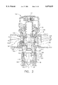
- FIG. 2 is a sectional view of the mixing valve of the present invention
- FIG. 3 is a top view of a first embodiment of a diffuser used in conjunction with the mixing valve of the present invention
- FIG. 4 is a cross-sectional view of the diffuser of FIG. 3, taken along line 4--4 in FIG. 3;
- FIG. 5 is a top view of a second embodiment of a diffuser used in conjunction with the mixing valve of the present invention.
- FIG. 6 is a cross-sectional view of the diffuser of FIG. 5, taken along line 6--6 in FIG. 5.
- a mixing valve 100 includes a body 112, a thermal actuator 114, a spool 116, a biasing spring 118, a body cover 120 and a temperature selection device 122.
- the body 112 incorporates a hot port, made up of an external hot port 124a and an internal hot port 124b, a cold port, made up of an external cold port 126a and an internal cold port 126b, and a mix port 128.
- Body 112 also includes a hot annular groove 156 and a cold annular groove 158.
- the body 112 is typically formed from forged or cast metal.
- the spool 116 is located between surface A of the body 112 and surface B of the body cover 120. Similar to the mixing valve 10 of FIG. 1, the distance between surface A of the body 112 and surface B of the body cover 120 is greater than the length l of spool 116. The difference in the distance between surface A of body 112 and surface B of body cover 120 and the spool length l is referred to as the spool stroke, which is the distance that the spool 116 can travel between the surface A of body 112 and surface B of body cover 120.
- Spool 116 includes an annular cold water chamber 134 and is supported and frictionally engaged within body 112 by O-ring seal 136. Spool 116 also includes external hub 200 which extends from the bottom surface 220 of spool 116.
- Thermal actuator 114 is an elongated version of the thermal actuator 14, having a longer piston 130 and a longer and narrower cup 132 than the piston 30 and cup 32, respectively of the thermal actuator 14. However, while being shaped differently from thermal actuator 14, thermal actuator 114 operates identically to thermal actuator 14 as described above. As stated above, thermal actuator 114 includes an actuator piston 130, which is biased against head 152 of spindle 140. Thermal actuator 114 is threadably coupled to spool 116 at region 200a within external hub 200 of spool 116, such that actuator piston 130 is centrally disposed within spool 116 and such that the actuator piston 130 travels in a direction along the longitudinal axis 146 of the spool 116.
- a mixing chamber 160 is formed between the bottom of spool 116 and an annular ring 162, which is part of cup 132 of thermal actuator 114.
- the configuration of the external hub 200 enables the thermal actuator 114 to be positioned further downstream from surface A of the body 112, thereby substantially increasing the length of the mixing chamber 160, as compared to the prior art device.
- This increase in the length of the mixing chamber 160 provides more space for the hot and cold water to mix before the mixture passes over the cup 132 of the thermal actuator 114, thus enabling a more thorough mix of the hot and cold water, as compared to the prior art device.
- a diffuser 202 is biased against annular ring 162 by bias spring 118, which has its other end engaged by a lip 206 of body 112.
- Diffuser 202 is shown in greater detail in FIG. 3, which is a top view of the diffuser 202 and FIG. 4, which is a cross-sectional view of the diffuser 202, taken along line 4--4 in FIG. 3.
- diffuser 202 includes a peripheral wall 210, a number of fins 212 projecting inwardly from the peripheral wall 210 toward the center of the diffuser 202, and an annular plate 214 projecting inwardly from the peripheral wall 210 to form an aperture 216.
- Aperture 216 has a diameter which is slightly larger that the outside diameter of the cup 132.
- the diffuser is formed from a mixture of polypropelene and fiberglass, however, it will be understood that the diffuser 202 may be formed from any suitable material. Also, diffuser 202 may be formed from a single piece of material, or the peripheral wall 210 and fins 212 may be formed separately from the annular plate 214 and then mounted onto the thermal actuator 114.
- FIG. 5 An alternative embodiment of the diffuser is shown at 302 in FIG. 5, which is a top view of the diffuser 302, and FIG. 6, which is a cross-sectional view of the diffuser 302, taken along line 6--6 in FIG. 5.
- the diffuser 302 includes a peripheral wall 310, a number of fins 312 projecting inwardly from the peripheral wall 310 toward the center of the diffuser 302, and an annular plate 314 projecting inwardly from the peripheral wall 310 to form an aperture 316.
- Aperture 316 has a diameter which is slightly larger that the outside diameter of the cup 132.
- the operation of the mixing valve 100 will now be described.
- the operation of the temperature selection device 122 is identical to that described with reference to the temperature selection device 22 of FIG. 1, and therefore will not be described with reference to the mixing valve 100.
- This mixed water then flows through diffuser 202, which preferably imparts rotation to the flow, thereby causing the flow of water to rotate around the cup 132, further agitating and mixing the water.
- diffuser 202 it is not essential for the flow to rotate to provide the increased mixing feature of the diffuser 202.
- the diffuser shown in FIGS. 5 and 6 is less likely to cause the flow of water to rotate than the diffuser shown in FIGS. 3 and 4.
- the diffuser 202 also acts to pull the water toward cup 132 by forcing the water through the aperture 216 in annular plate 214, thus allowing a more accurate sensing of the true average temperature of the mixed water. Furthermore, due to the orientation of bias spring 118, which is inverse from that in the prior art device, the mixed water 184 flows through the diffuser 202 and is discharged from valve 100 through mix port 128 without having to pass through the coils of bias spring 118, thereby eliminating the noise problem associated with the prior art mixing valve.
- the operation of the spool 116 and thermal actuator 114 is similar to the operation of the spool 16 and thermal actuator 14 described above. Specifically, if the temperature of the cold water supply decreases such that the thermal expansion material within cup 132 of thermal actuator expands, actuator piston 130 is pushed outwardly from thermal actuator 114 against head 152 of spindle 140. This causes thermal actuator 114 to pull spool 116 away from surface B of body cover 120 and toward surface A of body 112. As spool 116 is pulled toward surface A, the width of the internal hot port 124b decreases, thereby decreasing the amount of hot water which is allowed to pass into mixing chamber 160.
- thermal actuator 114 If the temperature of the hot water supply decreases, the opposite action occurs in thermal actuator 114 and, as piston 130 retracts into the thermal actuator 114, spool 116 is pushed toward surface B by bias spring 118. This causes the width of the internal hot port 124b to increase, thereby increasing the amount of hot water which is allowed to pass into mixing chamber 160. At the same time, as spool 116 is pushed toward surface B, the width of the internal cold port 126b decreases, thereby decreasing the amount of cold water which is allowed to pass through annular cold water chamber 134 and into mixing chamber 160. The resulting mix of water discharged through mix port 128 therefore has a temperature which is closer to the desired temperature set by the temperature selection device.
- thermostatic mixing valves A characteristic of thermostatic mixing valves is that when water is first drawn, either after a long period of no draws (i.e., overnight) or even shortly after a previous draw, the mix water temperature momentarily overshoots the set temperature. The reason for the overshoot is that as soon as the flow of water ceases, the thermal actuator starts to cool down. However, since the thermal actuator is trying to maintain the set temperature, it is looking for more hot water and less cold water. Accordingly, the width of the hot water port is increased and the width of the cold water port is decreased relative to a steady state condition.
- the hot and cold water enters the valve with the spool in a position that allows too much hot water and too little cold water to pass, thus resulting in a mix temperature higher than that which is set by the temperature selection device.
- This is a momentary condition which begins to correct itself as soon as the mix water contacts the thermal element. Since the thermal element reacts to the increased water temperature by reducing the width of the hot water port while increasing the width of the cold water port, the mix temperature quickly reverts to the desired level.
- the present invention provides a thermostatic mixing valve which facilitates the mixing of the cold and hot water before the water passes over the cup of the thermal actuator, thus allowing the thermal actuator to more accurately react to the temperature of the mixture, thus enabling the thermostatic mixing valve to more accurately maintain the temperature of the water output from the mix port of the mixing valve.
- the mixing valve includes a biasing spring arrangement that prevents the water from being directed away from the thermal actuator and does not vibrate, thus eliminating objectionable noises from the mixing valve during operation.
Landscapes
- Physics & Mathematics (AREA)
- General Physics & Mathematics (AREA)
- Engineering & Computer Science (AREA)
- Automation & Control Theory (AREA)
- Temperature-Responsive Valves (AREA)
- Multiple-Way Valves (AREA)
Abstract
Description
Claims (10)
Priority Applications (7)
| Application Number | Priority Date | Filing Date | Title |
|---|---|---|---|
| US09/362,411 US6079625A (en) | 1998-09-04 | 1999-07-28 | Thermostatic mixing valve |
| CA002337053A CA2337053C (en) | 1998-09-04 | 1999-09-03 | Improved thermostatic mixing valve |
| DE69928424T DE69928424T2 (en) | 1998-09-04 | 1999-09-03 | IMPROVED THERMOSTATIC MIXING VALVE |
| AU58071/99A AU5807199A (en) | 1998-09-04 | 1999-09-03 | Improved thermostatic mixing valve |
| AT99945480T ATE310269T1 (en) | 1998-09-04 | 1999-09-03 | IMPROVED THERMOSTATIC MIXING VALVE |
| PCT/US1999/020262 WO2000014615A1 (en) | 1998-09-04 | 1999-09-03 | Improved thermostatic mixing valve |
| EP99945480A EP1118049B1 (en) | 1998-09-04 | 1999-09-03 | Improved thermostatic mixing valve |
Applications Claiming Priority (3)
| Application Number | Priority Date | Filing Date | Title |
|---|---|---|---|
| US9909098P | 1998-09-04 | 1998-09-04 | |
| US9944498P | 1998-09-08 | 1998-09-08 | |
| US09/362,411 US6079625A (en) | 1998-09-04 | 1999-07-28 | Thermostatic mixing valve |
Publications (1)
| Publication Number | Publication Date |
|---|---|
| US6079625A true US6079625A (en) | 2000-06-27 |
Family
ID=27378733
Family Applications (1)
| Application Number | Title | Priority Date | Filing Date |
|---|---|---|---|
| US09/362,411 Expired - Lifetime US6079625A (en) | 1998-09-04 | 1999-07-28 | Thermostatic mixing valve |
Country Status (7)
| Country | Link |
|---|---|
| US (1) | US6079625A (en) |
| EP (1) | EP1118049B1 (en) |
| AT (1) | ATE310269T1 (en) |
| AU (1) | AU5807199A (en) |
| CA (1) | CA2337053C (en) |
| DE (1) | DE69928424T2 (en) |
| WO (1) | WO2000014615A1 (en) |
Cited By (37)
| Publication number | Priority date | Publication date | Assignee | Title |
|---|---|---|---|---|
| EP1189127A2 (en) * | 2000-09-15 | 2002-03-20 | Hansgrohe AG | Thermostatic valve |
| WO2002033500A1 (en) * | 2000-07-05 | 2002-04-25 | The Horne Engineering Co. Ltd | Thermostatic mixing valve |
| US20020134848A1 (en) * | 2001-03-22 | 2002-09-26 | Werner Heinzelmann | Thermostatically controlled mixing valve |
| US20030217775A1 (en) * | 2002-03-01 | 2003-11-27 | Cory Cousineau | Fluid valve |
| US20040000594A1 (en) * | 2002-06-26 | 2004-01-01 | Kohler Mira Limited | Thermostatic mixing valve |
| US6676024B1 (en) | 2002-09-05 | 2004-01-13 | Masco Corporation | Thermostatic valve with electronic control |
| US20040046037A1 (en) * | 2000-12-06 | 2004-03-11 | Swadling Jeremy Philip | Flow mixer |
| US20050116053A1 (en) * | 2003-12-02 | 2005-06-02 | Zoltan Goncze | Automatic compensating valve for individual shower and tub/shower combination fixtures |
| US20050139688A1 (en) * | 2003-12-31 | 2005-06-30 | Yang Tsai C. | Valve for mixing cold and hot water |
| JP2005188671A (en) * | 2003-12-26 | 2005-07-14 | San-Ei Faucet Mfg Co Ltd | Combination faucet |
| US20060090798A1 (en) * | 2004-11-01 | 2006-05-04 | Beagen Joseph W | Thermostatic mixing valves and systems |
| US20060124758A1 (en) * | 2004-12-15 | 2006-06-15 | Sansum Nigel P | Thermostatic mixing valves |
| US20060231638A1 (en) * | 2005-04-19 | 2006-10-19 | Jeffrey Belz | Electronic proportioning valve |
| US20070023535A1 (en) * | 2003-06-06 | 2007-02-01 | Cunningham Aaron C | Thermostatic mixing valve |
| US20070029395A1 (en) * | 2005-07-19 | 2007-02-08 | Gsa Industries (Aust.) Pty. Ltd. | Thermostatic mixing valve |
| WO2005062892A3 (en) * | 2003-12-23 | 2007-03-29 | Mi Llc | Device and methodology for improved mixing of liquids and solids |
| US20070277892A1 (en) * | 2006-06-02 | 2007-12-06 | Emech Control Limited | Mixing value and mixing device |
| US20080121282A1 (en) * | 2003-09-22 | 2008-05-29 | John William Green | Temperature Limiting Device Applicable To Single Lever Valves For Mixing Hot And Cold Liquids |
| CN101943275A (en) * | 2010-09-08 | 2011-01-12 | 常州市华鹏机械电器制造有限公司 | Automatic constant-temperature water mixing valve |
| CN101956840A (en) * | 2010-11-09 | 2011-01-26 | 常州有容电子有限公司 | Automatic constant temperature tap |
| CN101994859A (en) * | 2010-11-27 | 2011-03-30 | 常州福德机械有限公司 | Automatic constant temperature water outlet device |
| WO2011057480A1 (en) * | 2009-11-12 | 2011-05-19 | 路达(厦门)工业有限公司 | Structure of temperature controlling mixing valve |
| US8074894B2 (en) | 2008-11-18 | 2011-12-13 | Honeywell International Inc. | Secondary mixing valve hot port |
| CN102943914A (en) * | 2012-11-29 | 2013-02-27 | 常州天旭机电制造有限公司 | Valve body of emptying valve of solar hot water pipeline |
| EP2604896A1 (en) * | 2011-12-15 | 2013-06-19 | Flühs Drehtechnik GmbH | Mixing device for tap water |
| US8544760B2 (en) | 2001-08-24 | 2013-10-01 | Magarl, Llc | Mixing valve |
| US8733666B2 (en) | 2008-11-18 | 2014-05-27 | Honeywell International Inc. | Thermostatic mixing valve with tamper resistant adjustment feature |
| JP2015132319A (en) * | 2014-01-13 | 2015-07-23 | 株式会社ダンレイ | Hot water and cold water mixing valve |
| US20160011606A1 (en) * | 2013-03-07 | 2016-01-14 | Vernet | Thermostatic cartridge for controlling hot and cold fluids to be mixed |
| US20160018831A1 (en) * | 2014-07-21 | 2016-01-21 | Rostra Vernatherm, Llc | Self-Contained Thermal Mixing Valve |
| CN105605300A (en) * | 2016-03-18 | 2016-05-25 | 宁波华成阀门有限公司 | Bypass thermostatic mixing valve |
| US9504970B2 (en) | 2011-10-22 | 2016-11-29 | Magarl, Llc | Methods and apparatus for creating turbulence in a thermostatic mixing valve |
| IT201600108293A1 (en) * | 2016-10-26 | 2018-04-26 | Caleffi Spa | MIXER VALVE DEVICE |
| US10816106B2 (en) | 2014-12-23 | 2020-10-27 | Masco Canada Limited | Cartridge temperature limit control mechanism |
| US11003199B2 (en) * | 2016-07-21 | 2021-05-11 | Vernet | Mixing unit and mixer tap comprising such a mixing unit |
| US11680656B2 (en) | 2019-02-26 | 2023-06-20 | Grohe Ag | Mixing cartridge having a vortex element |
| EP4042002A4 (en) * | 2019-09-30 | 2023-11-01 | Kirpart Otomotiv Parçalari Sanayi Ve Ticaret A.S. | A thermostat assembly providing constant outlet temperature by adjusting mixing ratio autonomously |
Families Citing this family (5)
| Publication number | Priority date | Publication date | Assignee | Title |
|---|---|---|---|---|
| AU783187B2 (en) * | 2000-08-04 | 2005-10-06 | Reliance Worldwide Corporation (Aust.) Pty. Ltd. | Mixing valve |
| CN101498382B (en) * | 2008-12-25 | 2011-02-09 | 谢庆俊 | Single handle successive type thermostatic valve core |
| RU2523926C2 (en) * | 2009-02-26 | 2014-07-27 | Уоттс Индастриз Франс | Thermostatic mixing valve |
| IT1401123B1 (en) * | 2010-07-15 | 2013-07-12 | Caleffi Spa | THERMOSTATIC MIXER AND CONTROL METHOD. |
| WO2024056565A1 (en) | 2022-09-13 | 2024-03-21 | Pittway Sarl | Thermostatic mixing valve |
Citations (10)
| Publication number | Priority date | Publication date | Assignee | Title |
|---|---|---|---|---|
| US19488A (en) * | 1858-03-02 | Theodore christian | ||
| US3765604A (en) * | 1971-03-09 | 1973-10-16 | D Trubert | Mixing faucet |
| US3792812A (en) * | 1972-02-29 | 1974-02-19 | Knapp Alfons | Thermostatic mixing cock |
| US3929283A (en) * | 1973-11-13 | 1975-12-30 | Fonderie Soc Gen De | Thermostatic mixing apparatus and a related method for regulating temperature |
| US4607788A (en) * | 1982-05-26 | 1986-08-26 | Meynell Valves Limited | Mixing valve |
| US5129576A (en) * | 1985-08-07 | 1992-07-14 | Masco Corporation Of Indiana | Thermostatic pressure balanced valve assembly |
| US5148976A (en) * | 1991-03-15 | 1992-09-22 | The Horne Engineering Co., Ltd. | Thermostatic mixing valve |
| US5203496A (en) * | 1991-03-04 | 1993-04-20 | Lawler Manufacturing Co., Inc. | Thermostatic control valve with fluid mixing |
| US5323960A (en) * | 1991-03-04 | 1994-06-28 | Lawler Manufacturing Co., Inc. | Thermostatic control valve with fluid mixing and non-linear response characteristics |
| US5340018A (en) * | 1991-03-14 | 1994-08-23 | Masco Corporation Of Indiana | Thermostatically controlled mixing valve |
Family Cites Families (5)
| Publication number | Priority date | Publication date | Assignee | Title |
|---|---|---|---|---|
| USRE19488E (en) * | 1935-03-05 | Hot water temperature regulator | ||
| FR2295327A1 (en) * | 1974-12-20 | 1976-07-16 | Pont A Mousson | THERMOSTATIC MIXING VALVE |
| IT1273178B (en) * | 1994-05-05 | 1997-07-07 | Gevipi Ag | THERMOSTATIC MIXER DEVICE |
| DE4423240C1 (en) * | 1994-07-02 | 1996-02-22 | Hansa Metallwerke Ag | Thermostat valve with hollow cylindrical plug |
| IT1267148B1 (en) * | 1994-11-18 | 1997-01-28 | Gevipi Ag | THERMOSTATIC MIXING VALVE. |
-
1999
- 1999-07-28 US US09/362,411 patent/US6079625A/en not_active Expired - Lifetime
- 1999-09-03 EP EP99945480A patent/EP1118049B1/en not_active Expired - Lifetime
- 1999-09-03 WO PCT/US1999/020262 patent/WO2000014615A1/en active IP Right Grant
- 1999-09-03 CA CA002337053A patent/CA2337053C/en not_active Expired - Lifetime
- 1999-09-03 AU AU58071/99A patent/AU5807199A/en not_active Abandoned
- 1999-09-03 DE DE69928424T patent/DE69928424T2/en not_active Expired - Lifetime
- 1999-09-03 AT AT99945480T patent/ATE310269T1/en not_active IP Right Cessation
Patent Citations (10)
| Publication number | Priority date | Publication date | Assignee | Title |
|---|---|---|---|---|
| US19488A (en) * | 1858-03-02 | Theodore christian | ||
| US3765604A (en) * | 1971-03-09 | 1973-10-16 | D Trubert | Mixing faucet |
| US3792812A (en) * | 1972-02-29 | 1974-02-19 | Knapp Alfons | Thermostatic mixing cock |
| US3929283A (en) * | 1973-11-13 | 1975-12-30 | Fonderie Soc Gen De | Thermostatic mixing apparatus and a related method for regulating temperature |
| US4607788A (en) * | 1982-05-26 | 1986-08-26 | Meynell Valves Limited | Mixing valve |
| US5129576A (en) * | 1985-08-07 | 1992-07-14 | Masco Corporation Of Indiana | Thermostatic pressure balanced valve assembly |
| US5203496A (en) * | 1991-03-04 | 1993-04-20 | Lawler Manufacturing Co., Inc. | Thermostatic control valve with fluid mixing |
| US5323960A (en) * | 1991-03-04 | 1994-06-28 | Lawler Manufacturing Co., Inc. | Thermostatic control valve with fluid mixing and non-linear response characteristics |
| US5340018A (en) * | 1991-03-14 | 1994-08-23 | Masco Corporation Of Indiana | Thermostatically controlled mixing valve |
| US5148976A (en) * | 1991-03-15 | 1992-09-22 | The Horne Engineering Co., Ltd. | Thermostatic mixing valve |
Cited By (69)
| Publication number | Priority date | Publication date | Assignee | Title |
|---|---|---|---|---|
| US6820816B1 (en) | 2000-07-05 | 2004-11-23 | The Horne Engineering Co. Ltd. | Thermostatic mixing value |
| WO2002033500A1 (en) * | 2000-07-05 | 2002-04-25 | The Horne Engineering Co. Ltd | Thermostatic mixing valve |
| AU2001270757B2 (en) * | 2000-07-05 | 2006-10-05 | Horne Engineering Ltd | Thermostatic mixing valve |
| EP1189127A3 (en) * | 2000-09-15 | 2003-02-05 | Hansgrohe AG | Thermostatic valve |
| US6585167B2 (en) | 2000-09-15 | 2003-07-01 | Hansgrohe Ag | Thermostatic valve |
| EP1189127A2 (en) * | 2000-09-15 | 2002-03-20 | Hansgrohe AG | Thermostatic valve |
| US7073725B2 (en) * | 2000-12-06 | 2006-07-11 | Valquest Limited | Flow mixer |
| US20040046037A1 (en) * | 2000-12-06 | 2004-03-11 | Swadling Jeremy Philip | Flow mixer |
| US6726110B2 (en) * | 2001-03-22 | 2004-04-27 | Hansgrohe Ag | Thermostatically controlled mixing valve |
| US20020134848A1 (en) * | 2001-03-22 | 2002-09-26 | Werner Heinzelmann | Thermostatically controlled mixing valve |
| US8544760B2 (en) | 2001-08-24 | 2013-10-01 | Magarl, Llc | Mixing valve |
| US9081392B2 (en) | 2001-08-24 | 2015-07-14 | Magarl, Llc | Mixing valve |
| US9625920B2 (en) | 2001-08-24 | 2017-04-18 | Magarl, Llc | Mixing valve |
| US10216203B2 (en) | 2001-08-24 | 2019-02-26 | Magarl, Llc | Mixing valve |
| US10678277B2 (en) | 2001-08-24 | 2020-06-09 | Magarl, Llc | Mixing valve |
| US20030217775A1 (en) * | 2002-03-01 | 2003-11-27 | Cory Cousineau | Fluid valve |
| US20070221740A1 (en) * | 2002-06-26 | 2007-09-27 | Beck Nicholas J | Thermostatic mixing valve |
| US7240850B2 (en) | 2002-06-26 | 2007-07-10 | Kohler Mira Limited | Thermostatic mixing valve |
| GB2392225A (en) * | 2002-06-26 | 2004-02-25 | Kohler Mira Ltd | Improvements in or relating to thermostatic mixing valves |
| US20100123013A1 (en) * | 2002-06-26 | 2010-05-20 | Kohler Mira Limited | Thermostatic mixing valve |
| GB2392225B (en) * | 2002-06-26 | 2006-09-20 | Kohler Mira Ltd | Improvements in or relating to thermostatic mixing valves |
| US7669776B2 (en) * | 2002-06-26 | 2010-03-02 | Kohler Mira Limited | Thermostatic mixing valve |
| US20040000594A1 (en) * | 2002-06-26 | 2004-01-01 | Kohler Mira Limited | Thermostatic mixing valve |
| US6676024B1 (en) | 2002-09-05 | 2004-01-13 | Masco Corporation | Thermostatic valve with electronic control |
| US7665671B2 (en) * | 2003-06-06 | 2010-02-23 | Gsa Industries (Aust) Pty Ltd | Thermostatic mixing valve |
| US20070023535A1 (en) * | 2003-06-06 | 2007-02-01 | Cunningham Aaron C | Thermostatic mixing valve |
| US20080121282A1 (en) * | 2003-09-22 | 2008-05-29 | John William Green | Temperature Limiting Device Applicable To Single Lever Valves For Mixing Hot And Cold Liquids |
| US8376241B2 (en) * | 2003-09-25 | 2013-02-19 | Greens Industries Limited | Temperature limiting device applicable to single lever valves for mixing hot and cold liquids |
| US20050116053A1 (en) * | 2003-12-02 | 2005-06-02 | Zoltan Goncze | Automatic compensating valve for individual shower and tub/shower combination fixtures |
| US7163157B2 (en) | 2003-12-02 | 2007-01-16 | Watts Regulator Co. | Automatic compensating valve for individual shower and tub/shower combination fixtures |
| WO2005062892A3 (en) * | 2003-12-23 | 2007-03-29 | Mi Llc | Device and methodology for improved mixing of liquids and solids |
| EA009426B1 (en) * | 2003-12-23 | 2007-12-28 | М-Ай Л.Л.С. | Eductor and method for mixing solids and liquids |
| JP2005188671A (en) * | 2003-12-26 | 2005-07-14 | San-Ei Faucet Mfg Co Ltd | Combination faucet |
| US20050139688A1 (en) * | 2003-12-31 | 2005-06-30 | Yang Tsai C. | Valve for mixing cold and hot water |
| US7086602B2 (en) * | 2003-12-31 | 2006-08-08 | Tsai Chen Yang | Valve for mixing cold and hot water |
| US20060090798A1 (en) * | 2004-11-01 | 2006-05-04 | Beagen Joseph W | Thermostatic mixing valves and systems |
| US7744007B2 (en) | 2004-11-01 | 2010-06-29 | Honeywell International Inc. | Thermostatic mixing valves and systems |
| US20060124758A1 (en) * | 2004-12-15 | 2006-06-15 | Sansum Nigel P | Thermostatic mixing valves |
| US8517282B2 (en) * | 2004-12-15 | 2013-08-27 | Kohler Mira Limited | Thermostatic mixing valve responsive to pressure changes |
| EP1672257A1 (en) * | 2004-12-15 | 2006-06-21 | Kohler Mira Limited | Thermostatic mixing valve |
| US8167215B2 (en) * | 2004-12-15 | 2012-05-01 | Kohler Mira Limited | Thermostatic mixing valves utilizing wave springs |
| US20100219255A1 (en) * | 2004-12-15 | 2010-09-02 | Kohler Mira Limited | Thermostatic mixing valves |
| US20060231638A1 (en) * | 2005-04-19 | 2006-10-19 | Jeffrey Belz | Electronic proportioning valve |
| US20070029395A1 (en) * | 2005-07-19 | 2007-02-08 | Gsa Industries (Aust.) Pty. Ltd. | Thermostatic mixing valve |
| US20070277892A1 (en) * | 2006-06-02 | 2007-12-06 | Emech Control Limited | Mixing value and mixing device |
| US8733666B2 (en) | 2008-11-18 | 2014-05-27 | Honeywell International Inc. | Thermostatic mixing valve with tamper resistant adjustment feature |
| US8074894B2 (en) | 2008-11-18 | 2011-12-13 | Honeywell International Inc. | Secondary mixing valve hot port |
| WO2011057480A1 (en) * | 2009-11-12 | 2011-05-19 | 路达(厦门)工业有限公司 | Structure of temperature controlling mixing valve |
| CN101943275A (en) * | 2010-09-08 | 2011-01-12 | 常州市华鹏机械电器制造有限公司 | Automatic constant-temperature water mixing valve |
| CN101956840A (en) * | 2010-11-09 | 2011-01-26 | 常州有容电子有限公司 | Automatic constant temperature tap |
| CN101994859A (en) * | 2010-11-27 | 2011-03-30 | 常州福德机械有限公司 | Automatic constant temperature water outlet device |
| US9504970B2 (en) | 2011-10-22 | 2016-11-29 | Magarl, Llc | Methods and apparatus for creating turbulence in a thermostatic mixing valve |
| US10376849B2 (en) | 2011-10-22 | 2019-08-13 | Magarl, Llc | Methods and apparatus for creating turbulence in a thermostatic mixing valve |
| EP2604896A1 (en) * | 2011-12-15 | 2013-06-19 | Flühs Drehtechnik GmbH | Mixing device for tap water |
| CN102943914A (en) * | 2012-11-29 | 2013-02-27 | 常州天旭机电制造有限公司 | Valve body of emptying valve of solar hot water pipeline |
| US20160011606A1 (en) * | 2013-03-07 | 2016-01-14 | Vernet | Thermostatic cartridge for controlling hot and cold fluids to be mixed |
| US9823671B2 (en) * | 2013-03-07 | 2017-11-21 | Vernet | Thermostatic cartridge for controlling hot and cold fluids to be mixed |
| JP2015132319A (en) * | 2014-01-13 | 2015-07-23 | 株式会社ダンレイ | Hot water and cold water mixing valve |
| US20160018831A1 (en) * | 2014-07-21 | 2016-01-21 | Rostra Vernatherm, Llc | Self-Contained Thermal Mixing Valve |
| US9690305B2 (en) * | 2014-07-21 | 2017-06-27 | Rostra Vernatherm, Llc | Self-contained thermal mixing valve |
| US10816106B2 (en) | 2014-12-23 | 2020-10-27 | Masco Canada Limited | Cartridge temperature limit control mechanism |
| CN105605300B (en) * | 2016-03-18 | 2018-04-06 | 宁波华成阀门有限公司 | Bypass constant-temperature water mixing valve |
| CN105605300A (en) * | 2016-03-18 | 2016-05-25 | 宁波华成阀门有限公司 | Bypass thermostatic mixing valve |
| US11003199B2 (en) * | 2016-07-21 | 2021-05-11 | Vernet | Mixing unit and mixer tap comprising such a mixing unit |
| IT201600108293A1 (en) * | 2016-10-26 | 2018-04-26 | Caleffi Spa | MIXER VALVE DEVICE |
| WO2018077807A1 (en) * | 2016-10-26 | 2018-05-03 | Caleffi S.P.A. | Mixer valve device |
| US11448328B2 (en) | 2016-10-26 | 2022-09-20 | Caleffi S.P.A. | Mixer valve device |
| US11680656B2 (en) | 2019-02-26 | 2023-06-20 | Grohe Ag | Mixing cartridge having a vortex element |
| EP4042002A4 (en) * | 2019-09-30 | 2023-11-01 | Kirpart Otomotiv Parçalari Sanayi Ve Ticaret A.S. | A thermostat assembly providing constant outlet temperature by adjusting mixing ratio autonomously |
Also Published As
| Publication number | Publication date |
|---|---|
| AU5807199A (en) | 2000-03-27 |
| WO2000014615A1 (en) | 2000-03-16 |
| EP1118049A1 (en) | 2001-07-25 |
| EP1118049A4 (en) | 2003-08-06 |
| EP1118049B1 (en) | 2005-11-16 |
| DE69928424T2 (en) | 2006-08-03 |
| ATE310269T1 (en) | 2005-12-15 |
| CA2337053A1 (en) | 2000-03-16 |
| CA2337053C (en) | 2008-12-23 |
| DE69928424D1 (en) | 2005-12-22 |
Similar Documents
| Publication | Publication Date | Title |
|---|---|---|
| US6079625A (en) | Thermostatic mixing valve | |
| US5148976A (en) | Thermostatic mixing valve | |
| US7140394B2 (en) | Thermostatic control valve with fluid mixing | |
| JP2645179B2 (en) | Thermostatically controlled sanitary mixing faucet | |
| CA2462279A1 (en) | Mixing valve | |
| JP2004512588A (en) | Thermostatic mixing valve | |
| US6604687B2 (en) | Thermal fluid control valve | |
| JPH06147333A (en) | Thermostat mixing valve | |
| EP0448315B1 (en) | Improved thermostatic mixing valve | |
| US4164321A (en) | Thermostatic mixing valve for two fluids | |
| WO2002070930A2 (en) | Hot water temperature control valve system | |
| US3762638A (en) | Thermostatic mixing valve | |
| US7665671B2 (en) | Thermostatic mixing valve | |
| JP2002147645A (en) | Combination faucet | |
| JP2001254868A (en) | Water and hot water mixing device | |
| WO2017110213A1 (en) | Fluid control valve device for hot water combination faucet | |
| JP3740885B2 (en) | Hot water mixing device | |
| JP3410265B2 (en) | Hot water mixer tap | |
| JPH0643456U (en) | Thermostat mixing valve | |
| JPH09137877A (en) | Thermostat for mixing valve for water combination faucet | |
| JP2003042335A (en) | Combination faucet | |
| JPH08270810A (en) | Hot water and water mixing device | |
| JP2003028336A (en) | Combination faucet | |
| JP3077425B2 (en) | Constant pressure hot and cold water mixing equipment | |
| JP2002286161A (en) | Hot and cold water mixing cock |
Legal Events
| Date | Code | Title | Description |
|---|---|---|---|
| AS | Assignment |
Owner name: SPARCO INC., RHODE ISLAND Free format text: ASSIGNMENT OF ASSIGNORS INTEREST;ASSIGNOR:LEBKUCHNER, BENNO;REEL/FRAME:010221/0645 Effective date: 19990827 |
|
| STCF | Information on status: patent grant |
Free format text: PATENTED CASE |
|
| FEPP | Fee payment procedure |
Free format text: PAYOR NUMBER ASSIGNED (ORIGINAL EVENT CODE: ASPN); ENTITY STATUS OF PATENT OWNER: LARGE ENTITY |
|
| FEPP | Fee payment procedure |
Free format text: PAT HOLDER NO LONGER CLAIMS SMALL ENTITY STATUS, ENTITY STATUS SET TO UNDISCOUNTED (ORIGINAL EVENT CODE: STOL); ENTITY STATUS OF PATENT OWNER: LARGE ENTITY |
|
| REFU | Refund |
Free format text: REFUND - SURCHARGE, PETITION TO ACCEPT PYMT AFTER EXP, UNINTENTIONAL (ORIGINAL EVENT CODE: R2551); ENTITY STATUS OF PATENT OWNER: LARGE ENTITY |
|
| FPAY | Fee payment |
Year of fee payment: 4 |
|
| AS | Assignment |
Owner name: HONEYWELL INTERNATIONAL INC., NEW JERSEY Free format text: ASSIGNMENT OF ASSIGNORS INTEREST;ASSIGNOR:SPARCO INC.;REEL/FRAME:018837/0177 Effective date: 19991222 |
|
| RR | Request for reexamination filed |
Effective date: 20070314 |
|
| FPAY | Fee payment |
Year of fee payment: 8 |
|
| FPAY | Fee payment |
Year of fee payment: 12 |
|
| AS | Assignment |
Owner name: JPMORGAN CHASE BANK, N.A., AS ADMINISTRATIVE AGENT, NEW YORK Free format text: SECURITY INTEREST;ASSIGNOR:ADEMCO INC.;REEL/FRAME:047337/0577 Effective date: 20181025 Owner name: JPMORGAN CHASE BANK, N.A., AS ADMINISTRATIVE AGENT Free format text: SECURITY INTEREST;ASSIGNOR:ADEMCO INC.;REEL/FRAME:047337/0577 Effective date: 20181025 |
|
| AS | Assignment |
Owner name: ADEMCO INC., MINNESOTA Free format text: ASSIGNMENT OF ASSIGNORS INTEREST;ASSIGNOR:HONEYWELL INTERNATIONAL INC.;REEL/FRAME:047785/0166 Effective date: 20180729 |