EP2604472A1 - Hubladebühne - Google Patents
Hubladebühne Download PDFInfo
- Publication number
- EP2604472A1 EP2604472A1 EP12008328.2A EP12008328A EP2604472A1 EP 2604472 A1 EP2604472 A1 EP 2604472A1 EP 12008328 A EP12008328 A EP 12008328A EP 2604472 A1 EP2604472 A1 EP 2604472A1
- Authority
- EP
- European Patent Office
- Prior art keywords
- bolt
- securing means
- slot
- tailgate according
- loading
- Prior art date
- Legal status (The legal status is an assumption and is not a legal conclusion. Google has not performed a legal analysis and makes no representation as to the accuracy of the status listed.)
- Granted
Links
Images


Classifications
-
- B—PERFORMING OPERATIONS; TRANSPORTING
- B60—VEHICLES IN GENERAL
- B60P—VEHICLES ADAPTED FOR LOAD TRANSPORTATION OR TO TRANSPORT, TO CARRY, OR TO COMPRISE SPECIAL LOADS OR OBJECTS
- B60P1/00—Vehicles predominantly for transporting loads and modified to facilitate loading, consolidating the load, or unloading
- B60P1/44—Vehicles predominantly for transporting loads and modified to facilitate loading, consolidating the load, or unloading having a loading platform thereon raising the load to the level of the load-transporting element
-
- F—MECHANICAL ENGINEERING; LIGHTING; HEATING; WEAPONS; BLASTING
- F16—ENGINEERING ELEMENTS AND UNITS; GENERAL MEASURES FOR PRODUCING AND MAINTAINING EFFECTIVE FUNCTIONING OF MACHINES OR INSTALLATIONS; THERMAL INSULATION IN GENERAL
- F16C—SHAFTS; FLEXIBLE SHAFTS; ELEMENTS OR CRANKSHAFT MECHANISMS; ROTARY BODIES OTHER THAN GEARING ELEMENTS; BEARINGS
- F16C11/00—Pivots; Pivotal connections
- F16C11/02—Trunnions; Crank-pins
-
- F—MECHANICAL ENGINEERING; LIGHTING; HEATING; WEAPONS; BLASTING
- F16—ENGINEERING ELEMENTS AND UNITS; GENERAL MEASURES FOR PRODUCING AND MAINTAINING EFFECTIVE FUNCTIONING OF MACHINES OR INSTALLATIONS; THERMAL INSULATION IN GENERAL
- F16C—SHAFTS; FLEXIBLE SHAFTS; ELEMENTS OR CRANKSHAFT MECHANISMS; ROTARY BODIES OTHER THAN GEARING ELEMENTS; BEARINGS
- F16C11/00—Pivots; Pivotal connections
- F16C11/04—Pivotal connections
- F16C11/045—Pivotal connections with at least a pair of arms pivoting relatively to at least one other arm, all arms being mounted on one pin
Definitions
- the invention relates to a tail lift according to the preamble of claim 1.
- Tail lifts are used to facilitate the loading and unloading of heavy goods in particular for vehicles of all kinds.
- these tail lifts have a lifting platform that can be raised and lowered and, in general, also swivellably hinged to a vehicle.
- the loading platform is held for this purpose on a hoist, preferably in the region of the rear of a structure of the vehicle.
- the hoist usually has at least one linear drive, such as a hydraulic cylinder or an electric motor driven threaded spindle for lifting or lowering the loading platform.
- at least one further linear drive is preferably provided.
- the hoist is usually attached to a support device, in particular on a support tube which is connected to the vehicle, such as in the region of the vehicle frame or its longitudinal members.
- the loading platform is height adjustable in parallel planes.
- the link arms are preferably connected via transverse hinge pin with corresponding receptacles of the loading platform on the one hand and the support device on the other hand, as well as the linear drives.
- the bolts are secured against accidental slipping out.
- the bolts typically have a wider head at one end and are provided at the opposite end with a securing pin as securing means.
- the distance between the bolt head and cotter pin is usually so large that the bolt in its axial direction is still a small piece movable.
- the securing pin does not prevent any rotational movement of the bolt relative to the component adjacent to the securing pin. This component is in most cases the mount for the handlebar arm or linear drive.
- the bolt undergoes a reduction in cross-section over time or the recordings for the bolt knock out over time, creating additional game arises, which is only very limited admissible for tail lifts for reasons of safety at work. This extra clearance can be delayed by more frequent maintenance or more expensive materials.
- Object of the present invention is to provide a tail lift, with hinge pin in which during operation additional play to a lesser extent than before.
- a tail lift to solve this problem has the features of claim 1.
- the securing means prevents movement of the bolt in at least one direction.
- the bolt should be kept as free of play, at least in one direction of movement.
- the securing means is connected to the bolt and arranged so that movement of the bolt is prevented, at least relative to a component adjacent to the securing means.
- several securing means may be present, which cooperate.
- the securing means is in particular separable from the bolt or an independent component.
- the securing means prevents movement of the bolt in its axial direction.
- the bolt can be formed without a head.
- a design of the securing means is such that a movement of the bolt in the circumferential direction (rotational movement) is prevented, in particular relative to an adjacent component, such as a link arm or linear drive or a receptacle for this.
- the securing means can be firmly connected to the bolt.
- the securing means prevents any movement of the bolt, namely in the axial direction and at the same time in the circumferential direction (rotational movement).
- the bolt is preferably free of play after installation. The hiring in the course of operation game is then minimal.
- the bolt is connected by the securing means with an adjacent component, in particular with a link arm or linear drive or with a receptacle for said components.
- the connection described is fixed but solvable for disassembly required in case of maintenance.
- the bolt may have on its surface at least one recess or recess, in particular for positive engagement or for use of the securing means on or in the bolt.
- the recess or recess has a contact surface for the securing means and is in particular at one end of the bolt on the circumference of the same, arranged near an end face of the bolt.
- the bolt has on its surface two mutually opposite recesses or recesses, each with at least one contact surface for securing means. It can be provided one or more securing means, in particular a common for both contact surfaces.
- the recesses are in particular transverse axial grooves, preferably with mutually parallel side walls.
- the side walls may be aligned parallel to an adjacent, transverse axial end face of the bolt.
- the grooves each have at least one contact surface for the attachment of the securing means, wherein the contact surfaces are preferably formed flat.
- the contact surfaces are in particular floors of the grooves.
- two opposing abutment surfaces of two grooves of the respective bolt extend antiparallel to each other, such that the distance of the abutment surfaces from each other along their Lengthening changed.
- securing means with at least one contact surface, which comes to a correspondingly formed contact surface of the bolt to the plant.
- the securing means is provided with a slot to form two opposing, in particular planar bearing surfaces. The latter can come to lie on the contact surfaces of the bolt.
- the contact surfaces of the securing means run anti-parallel to one another to form a spacing between the contact surfaces which increases toward a slot opening.
- the bending of the contact surfaces of the securing means is preferably matched to the angle between the contact surfaces of the grooves of the bolt. This allows a sliding of the securing means on the bolt into a play-free position and to obtain a tight-fitting connection between the bolt and securing means.
- the securing means can be connected to an adjacent link arm or linear drive or a receptacle for this, in particular such that the securing means can be fixed in various positions on the receptacle, on the link arm or linear drive.
- the securing means is then no longer movable. If there is a stable connection between securing means and bolts, then the latter is also fixed without play.
- the securing means is a tab or plate with a slot on the one hand and a slot or slot on the other hand, preferably coaxially or axially parallel to each other.
- the provided at one end, in particular wedge-shaped slot engages in corresponding grooves or depressions on the bolt, while the provided at the other end slot or slot is provided for receiving a connecting means.
- the connecting means may for example be a screw, with which the securing means on the link arm or linear drive or a receptacle is fixed for this purpose.
- Slot or slot for receiving the connecting means allow the fixation of the securing means on an adjacent component in slightly different positions without this Fixation as tight as possible or backlash-free connection between securing means and bolt is loosened.
- the tab is to be understood in the broadest sense and may also be a plate, a metal strip or something similar.
- a pin, mandrel or wedge are provided as securing means, which in particular can be inserted transversely into an opening in the bolt and which can be connected to a link arm or linear drive or a receptacle for this purpose.
- This type of construction is a reversal of the aforementioned embodiment.
- the securing means is received by the bolt, while previously the securing means engages around the bolt.
- the securing means with an adjacent link arm or linear drive or a receptacle is connectable thereto, in particular such that the securing means in different positions on the arm or linear drive or the recording can be fixed.
- the securing means is a tab or plate with a slot, wherein the slot is wedge-shaped with removable in its longitudinal direction and the bolt on its surface two opposite each other Recesses or recesses which collectively receive the slot and are formed corresponding thereto.
- the invention can be used advantageously for all types of tail lifts with articulated bolts and vehicles equipped accordingly.
- An in Fig. 1 Shelf lift shown for a vehicle with cargo space has a hoist 15, which moves a loading platform 16 at the rear of a vehicle 17 parallel to the ground up and down and pivots to close the cargo space around an axis.
- the hoist 15 is attached to a support tube or support section 18 of the vehicle 17.
- the hoist 15 consists of linear drives and handlebars.
- the linear actuators are, for example, hydraulic cylinders or electric motor driven spindles. Shown here are based on the vehicle sides left and right each a pivot cylinder 19, 20 for pivoting the loading platform 16, a lifting cylinder 21, 22 for raising and lowering the loading platform 16 and a link arm 23, 24, via which the loading platform 16 with the support tube 18th connected is. Swivel cylinders and handlebar arms form parallelograms.
- Swivel cylinder, lifting cylinder and handlebars are articulated in receptacles 25, 26 on the support tube 18.
- the receptacles 25, 26 each have a pin 27, 28, 29.
- the swivel cylinders, lifting cylinders and link arms are articulated in the region of the loading platform 16 or to one another. The latter is in Fig. 2 seen.
- the lifting cylinder 21 is connected there via a bolt 30 near the loading platform 16 with the link arm 23. Opposite ends of Lifting cylinder 21 and link arm 23 are held in the receptacle 26 to the bolt 28, 29.
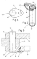
- One or more of the bolts 27 to 30 are formed in a special way and provided with a special securing means. This will be described below with reference to the bolt 28 and in conjunction with the FIGS. 3 to 10 explains:
- the bolt 28 in the receptacle 26 for the link arm 23 is cylindrical, without protruding head, and has at one end 31 a circumferential chamfer 32. This facilitates the insertion of the bolt 28 in the receptacle 26th
- the bolt 28 has two depressions 34, 35 lying opposite one another over the circumference. These are formed in the manner of grooves, each with bottom surface 36 and two mutually parallel side surfaces 37, 38.
- the bottom surfaces 36 are planar and form tendons to the peripheral circle 39 of the bolt 28.
- the bottom surfaces 36 extend to each other at a slight angle, see Fig. 7 , are therefore not aligned completely parallel to each other.
- the planes formed by the bottom surfaces 36 extend in the direction between the side surfaces 37, 38 but parallel to a longitudinal axis 40 of the bolt 28th
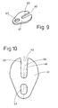
- the depressions 34, 35 provided near the end 33 serve to receive a securing means provided as a bolt securing device, which is designed here as an oval plate 41 and has a slot 42 at the wide end and a slot 43 at the narrow end. Slot 42 and slot 43 extend along a major axis 44.
- the plate 41 is at least in the region of the slot 42 and adjacent thereto dimensioned so that a precise fit in the recesses 34, 35 is possible, that is, the thickness of the plate 41 corresponds to the distance between the side surfaces 37, 38 of the groove-like recesses 34, 35 in the bolt 28 ( 3 and 4 ).
- the slot 42 is slightly wedge-shaped with an open end and has as abutment surfaces side surfaces 45, 46, corresponding to the effective as abutment surfaces bottom surfaces 36 of the recesses 34, 35 in the bolt 28.
- the side surfaces 45, 46 to each other formed slightly antiparallel, and preferably equally, so that the slot 42 has an increasing width to the open end.
- the plate 41 can be pushed up to a play-free system in the recesses 34, 35 on the bolt 28 or even pressed.
- Bolt 28 and securing means or plate 41 are connected in this way without play and tight together.
- the bolt 28 is inserted with attached plate 41 as a hinge pin in the receptacles 25, 26 with interposed link arm 23 to rest the plate 41 on the receptacle 26, see FIG. 5 ,
- the plate 41 is fixed by a screw 47 in the receptacle 26.
- the screw 47 extends through the slot 43 in a provided in the receptacle 26 thread 48.
- the slot 43 allows different positions of the plate 41 relative to the receptacle 26 and the screw 47.
- the screw 47 can be tightened without doing so the tight connection between pin 28 and plate 41 is released. This also results in a play-free connection of the securing means, in particular the plate 41, with the steering arm 23 or another component of the loading platform 16, the hoist 15 and / or the vehicle.
- the described embodiment of the bolt 28 with the cross-axially plugged plate 41 allows a backlash-free fixation of the bolt 28 on the receptacle 26.
- a movement of the bolt 28 relative to the receptacles 25, 26 and the arm 23 is minimized or even completely prevented in this way. Accordingly, the wear of the bolt 28 during operation is minimal.
- the bolt has the best possible life.
Landscapes
- Engineering & Computer Science (AREA)
- General Engineering & Computer Science (AREA)
- Mechanical Engineering (AREA)
- Transportation (AREA)
- Forklifts And Lifting Vehicles (AREA)
- Jib Cranes (AREA)
Abstract
Description
- Die Erfindung betrifft eine Hubladebühne gemäß dem Oberbegriff des Anspruchs 1.
- Hubladebühnen dienen dazu, bei Fahrzeugen aller Art das Be- und Entladen insbesondere schwerer Güter zu erleichtern. Dazu verfügen diese Hubladebühnen über eine heb- und senkbar und im Allgemeinen auch schwenkbar an einem Fahrzeug angelenkte Ladeplattform. Die Ladeplattform ist zu diesem Zweck an einem Hubwerk gehalten, vorzugsweise im Bereich der Rückseite eines Aufbaus des Fahrzeugs. Das Hubwerk weist üblicherweise zumindest einen Linearantrieb, wie beispielsweise einen Hydraulikzylinder oder eine elektromotorisch antreibbare Gewindespindel zum Heben bzw. Senken der Ladeplattform auf. Zum Verschwenken der Ladeplattform ist vorzugsweise wenigstens ein weiterer Linearantrieb vorgesehen. Das Hubwerk ist im Regelfall an einer Tragvorrichtung befestigt, insbesondere an einem Tragrohr, welches mit dem Fahrzeug verbunden ist, etwa im Bereich von dessen Fahrzeugrahmen bzw. dessen Längsträgern. Durch eine parallelogrammförmige Ausbildung des Hubwerks, vorzugsweise mit wenigstens zwei, zumindest im Wesentlichen parallel verschwenkbaren Lenkerarmen, ist die Ladeplattform in parallelen Ebenen höhenverstellbar.
- Die Lenkerarme sind vorzugsweise über quergerichtete Gelenk-Bolzen mit entsprechenden Aufnahmen der Ladeplattform einerseits und der Tragvorrichtung andererseits verbunden, ebenso die Linearantriebe. Soweit Bolzen-Verbindungen vorgesehen sind, sind die Bolzen gegen unbeabsichtigtes Herausrutschen gesichert. Hierzu weisen die Bolzen typischerweise an einem Ende einen breiteren Kopf auf und sind am gegenüberliegenden Ende mit einem Sicherungssplint als Sicherungsmittel versehen.
- Der Abstand zwischen Bolzenkopf und Sicherungssplint ist in der Regel so groß, dass der Bolzen in seiner Axialrichtung noch ein kleines Stück bewegbar ist. Außerdem verhindert der Sicherungssplint keine Drehbewegung des Bolzens relativ zu dem dem Sicherungssplint benachbarten Bauteil. Bei diesem Bauteil handelt es sich in den meisten Fällen um die Aufnahme für den Lenkerarm oder Linearantrieb.
- Durch das genannte Spiel erfährt der Bolzen mit der Zeit eine Querschnittsverringerung oder die Aufnahmen für den Bolzen schlagen mit der Zeit aus, wodurch zusätzliches Spiel entsteht, welches gerade für Hubladebühnen aus Gründen der Arbeitssicherheit nur sehr begrenzt zulässig ist. Dieses zusätzliche Spiel kann durch häufigere Wartung oder teurere Werkstoffe verzögert werden.
- Aufgabe der vorliegenden Erfindung ist die Schaffung einer Hubladebühne, mit Gelenk-Bolzen, bei denen im laufenden Betrieb zusätzliches Spiel in geringerem Maße als bisher auftritt.
- Eine Hubladebühne zur Lösung dieser Aufgabe weist die Merkmale des Anspruchs 1 auf. Danach ist vorgesehen, dass das Sicherungsmittel eine Bewegung des Bolzens in mindestens eine Richtung verhindert. Der Bolzen soll möglichst spielfrei gehalten sein, zumindest in einer Bewegungsrichtung. Vorzugsweise ist das Sicherungsmittel mit dem Bolzen verbunden und so angeordnet, dass eine Bewegung des Bolzens verhindert wird, zumindest relativ zu einem dem Sicherungsmittel benachbarten Bauteil. Auch können mehrere Sicherungsmittel vorhanden sein, die zusammenwirken. Das Sicherungsmittel ist insbesondere vom Bolzen trennbar bzw. ein eigenständiges Bauteil.
- Vorteilhafterweise verhindert das Sicherungsmittel eine Bewegung des Bolzens in seiner Axialrichtung. Der Bolzen kann so ohne Kopf ausgebildet sein.
- Bevorzugt ist eine Ausbildung des Sicherungsmittels derart, dass eine Bewegung des Bolzens in Umfangsrichtung (Drehbewegung) verhindert wird, insbesondere relativ zu einem benachbarten Bauteil, etwa zu einem Lenkerarm oder Linearantrieb oder einer Aufnahme hierfür. Dabei kann das Sicherungsmittel mit dem Bolzen fest verbunden sein.
- Nach einem weiteren Gedanken der Erfindung verhindert das Sicherungsmittel jedwede Bewegung des Bolzens, nämlich in Axialrichtung und zugleich in Umfangsrichtung (Drehbewegung). Der Bolzen ist nach dem Einbau vorzugsweise spielfrei. Das sich im Laufe des Betriebes einstellende Spiel ist dann minimal.
- Vorteilhafterweise ist der Bolzen durch das Sicherungsmittel mit einem benachbarten Bauteil verbunden, insbesondere mit einem Lenkerarm oder Linearantrieb oder mit einer Aufnahme für die genannten Bauteile. Die beschriebene Verbindung ist fest aber lösbar für eine im Wartungsfall erforderliche Demontage.
- Der Bolzen kann an seiner Oberfläche mindestens eine Vertiefung oder Ausnehmung aufweisen, insbesondere zur formschlüssigen Anlage oder zum Einsatz des Sicherungsmittels am oder in den Bolzen. Mit diesem Merkmal ist der Bolzen gegen Verdrehen und/oder gegen axiales Verschieben sicherbar. Vorzugsweise weist die Vertiefung oder Ausnehmung eine Anlagefläche für das Sicherungsmittel auf und ist insbesondere an einem Ende des Bolzens am Umfang desselben, nahe einer Stirnfläche des Bolzens angeordnet.
- Nach einem weiteren Gedanken der Erfindung weist der Bolzen an seiner Oberfläche zwei einander gegenüberliegende Vertiefungen oder Ausnehmungen auf, jeweils mit mindestens einer Anlagefläche für Sicherungsmittel. Es können ein oder mehrere Sicherungsmittel vorgesehen sein, insbesondere ein gemeinsames für beide Anlageflächen.
- Vorteilhafterweise sind die Vertiefungen insbesondere queraxiale Nuten, vorzugweise mit jeweils zueinander parallelen Seitenwänden. Auch können die Seitenwände parallel zu einer benachbarten, queraxialen Stirnfläche des Bolzen ausgerichtet sein.
- Bevorzugt ist eine Ausführung, bei der die Nuten jeweils mindestens eine Anlagefläche zur Anlage des Sicherungsmittels aufweisen, wobei die Anlageflächen vorzugsweise plan ausgebildet sind. Bei den Anlageflächen handelt es sich insbesondere um Böden der Nuten.
- Nach einem weiteren Gedanken der Erfindung sind zwei einander gegenüber liegende Anlageflächen von zwei Nuten des jeweiligen Bolzens antiparallel zueinander verlaufen, derart, dass sich der Abstand der Anlageflächen zueinander entlang ihrer Längserstreckung verändert. Mit den derart angeordneten Anlageflächen ist die Verwendung zentrierend wirkender Sicherungsmittel möglich.
- Im Rahmen der Erfindung liegt auch ein Sicherungsmittel mit mindestens einer Anlagefläche, welche an einer korrespondierend ausgebildeten Anlagefläche des Bolzens zur Anlage kommt. Dadurch ist eine eindeutige Positionierung des Sicherungsmittels relativ zum Bolzen möglich.
- Vorteilhafterweise ist das Sicherungsmittel mit einem Schlitz versehen unter Bildung von zwei einander gegenüberliegenden, insbesondere planen Anlageflächen. Letztere können an den Anlageflächen des Bolzens zu liegen kommen.
- Nach einem weiteren Gedanken der Erfindung verlaufen die Anlageflächen des Sicherungsmittels antiparallel zueinander zur Bildung eines sich zu einer Schlitzöffnung hin vergrößernden Abstands zwischen den Anlageflächen. Die Abwinkelung der Anlageflächen des Sicherungsmittels ist vorzugsweise abgestimmt auf den Winkel zwischen den Anlageflächen der Nuten des Bolzens. Dies ermöglicht ein Aufschieben des Sicherungsmittels auf den Bolzen bis in eine spielfreie Position und bis zum Erhalt einer stramm sitzenden Verbindung zwischen Bolzen und Sicherungsmittel.
- Nach einem weiteren Gedanken der Erfindung ist das Sicherungsmittel mit einem benachbarten Lenkerarm oder Linearantrieb oder einer Aufnahme hierfür verbindbar, insbesondere derart, dass das Sicherungsmittel in verschiedene Positionen an der Aufnahme, am Lenkerarm oder Linearantrieb festlegbar ist. Das Sicherungsmittel ist dann nicht mehr bewegbar. Besteht eine stabile Verbindung zwischen Sicherungsmittel und Bolzen, so ist auch letzterer spielfrei fixiert.
- Vorteilhafterweise ist das Sicherungsmittel eine Lasche oder Platte mit einem Schlitz einerseits und einem Langloch oder Schlitz andererseits, vorzugsweise koaxial oder achsparallel zueinander. Der an einem Ende vorgesehene, insbesondere keilförmige Schlitz greift in korrespondierende Nuten oder Vertiefungen am Bolzen, während das am anderen Ende vorgesehene Langloch oder der Schlitz für die Aufnahme eines Verbindungsmittels vorgesehen ist. Das Verbindungsmittel kann beispielsweise eine Schraube sein, mit der das Sicherungsmittel am Lenkerarm oder Linearantrieb oder einer Aufnahme hierfür fixiert ist. Langloch oder Schlitz für die Aufnahme des Verbindungsmittels ermöglichen die Fixierung des Sicherungsmittels an einem benachbarten Bauteil in leicht unterschiedlichen Positionen, ohne dass bei dieser Fixierung die möglichst stramme oder spielfreie Verbindung zwischen Sicherungsmittel und Bolzen gelockert wird. Die Lasche ist im weitesten Sinne zu verstehen und kann auch eine Platte, ein Blechstreifen oder etwas ähnliches sein.
- Nach einem weiteren Gedanken der Erfindung sind ein Stift, Dorn oder Keil als Sicherungsmittel vorgesehen, welches insbesondere queraxial in eine Öffnung am Bolzen einsetzbar ist und welches mit einem Lenkerarm oder Linearantrieb oder einer Aufnahme hierfür verbindbar ist. Bei dieser Bauart handelt es sich um eine Umkehrung der zuvor genannten Ausführung. Das Sicherungsmittel wird vom Bolzen aufgenommen, während zuvor das Sicherungsmittel den Bolzen umgreift.
- Im Rahmen der Erfindung liegt auch eine Hubladebühne, bei der das Sicherungsmittel mit einem benachbarten Lenkerarm oder Linearantrieb oder einer Aufnahme hierfür verbindbar ist, insbesondere derart, dass das Sicherungsmittel in verschiedenen Positionen an Lenkerarm oder Linearantrieb oder der Aufnahme festlegbar ist.
- Schließlich weist eine bevorzugte Ausführung der Erfindung die Merkmale aus dem Oberbegriff des Anspruchs 2 auf, wobei das Sicherungsmittel eine Lasche oder Platte mit einem Schlitz ist, wobei der Schlitz keilförmig ausgebildet ist mit in seiner Längsrichtung abnehmbarer Weite und der Bolzen an seiner Oberfläche zwei einander gegenüberliegende Vertiefungen oder Ausnehmungen aufweist, welche gemeinsam den Schlitz aufnehmen und hierzu korrespondierend ausgebildet sind.
- Die Erfindung ist für alle Bauarten von Hubladebühnen mit Gelenk-Bolzen und entsprechend ausgestattete Fahrzeuge vorteilhaft verwendbar.
- Weitere Merkmale der Erfindung ergeben sich aus der Beschreibung im Übrigen und aus den Ansprüchen.
- Vorteilhafte Ausführungsformen der Erfindung werden nachfolgend anhand der Zeichnung näher erläutert. Es zeigen:
- Fig. 1
- eine perspektivische Ansicht einer Hubladebühne,
- Fig. 2
- einen vergrößerten Ausschnitt aus
Figur 1 , - Fig. 3
- eine perspektivische Ansicht eines Bolzens mit Sicherungsmittel,
- Fig. 4
- eine stirnseitige Ansicht des Bolzens mit Sicherungsmittel gem.
Fig. 3 , - Fig. 5
- den Bolzen mit Sicherungsmittel gem.
Fig. 3 in einer Längsseitenansicht und eingesetzt in eine Aufnahme mit Lenkerarm, - Fig. 6
- den Bolzen in einer Längsseitenansicht,
- Fig. 7
- einen Schnitt durch den Bolzen gemäß
Fig. 6 entlang der Linie VII-VII, - Fig. 8
- eine perspektivische Darstellung des Bolzens gem.
Fig. 6 , - Fig. 9
- eine perspektivische Darstellung des Sicherungsmittels, einer Lasche
- Fig. 10
- eine Seitenansicht des Sicherungsmittels gem.
Fig. 9 . - Eine in
Fig. 1 gezeigte Hubladebühne für ein Fahrzeug mit Laderaum weist ein Hubwerk 15 auf, welches eine Ladeplattform 16 an der Rückseite eines Fahrzeugs 17 parallel zum Boden aufwärts und abwärts bewegt und zum Verschließen des Laderaums um eine Achse schwenkt. Hierzu ist das Hubwerk 15 an einem Tragrohr bzw. Tragprofil 18 des Fahrzeugs 17 befestigt. - Im Wesentlichen besteht das Hubwerk 15 aus Linearantrieben und Lenkerarmen. Bei den Linearantrieben handelt es sich beispielsweise um Hydraulikzylinder oder elektromotorisch angetriebene Spindeln. Gezeigt sind hier bezogen auf die Fahrzeugseiten links und rechts je ein Schwenkzylinder 19, 20 zum Schwenken der Ladeplattform 16, ein Hubzylinder 21, 22 zum Heben und Senken der Ladeplattform 16 sowie ein Lenkerarm 23, 24, über den die Ladeplattform 16 mit dem Tragrohr 18 verbunden ist. Schwenkzylinder und Lenkerarme bilden Parallelogramme.
- Schwenkzylinder, Hubzylinder und Lenkerarme sind in Aufnahmen 25, 26 am Tragrohr 18 gelenkig gelagert. Hierzu weisen die Aufnahmen 25, 26 jeweils einen Bolzen 27, 28, 29 auf. In ähnlicher oder analoger Weise sind die Schwenkzylinder, Hubzylinder und Lenkerarme im Bereich der Ladeplattform 16 oder aneinander angelenkt. Letzteres ist in
Fig. 2 ersichtlich. Der Hubzylinder 21 ist dort über einen Bolzen 30 nahe der Ladeplattform 16 mit dem Lenkerarm 23 verbunden. Gegenüberliegende Enden von Hubzylinder 21 und Lenkerarm 23 sind in der Aufnahme 26 an den Bolzen 28, 29 gehalten. - Einer oder mehrere der Bolzen 27 bis 30 sind in besonderer Weise ausgebildet und mit einem speziellen Sicherungsmittel versehen. Dies wird nachfolgend anhand des Bolzens 28 und in Verbindung mit den
Figuren 3 bis 10 erläutert: - Der Bolzen 28 in der Aufnahme 26 für den Lenkerarm 23 ist zylindrisch ausgebildet, ohne überstehenden Kopf, und weist an einem Ende 31 eine umlaufende Fase 32 auf. Dies erleichtert das Einführen des Bolzens 28 in die Aufnahme 26.
- Am gegenüberliegenden Ende 33 weist der Bolzen 28 zwei einander über den Umfang gegenüberliegende Vertiefungen 34, 35 auf. Diese sind nach Art von Nuten ausgebildet, jeweils mit Bodenfläche 36 und zwei zueinander parallelen Seitenflächen 37, 38. Dabei sind die Bodenflächen 36 plan und bilden Sehnen zum Umfangskreis 39 des Bolzens 28. Außerdem verlaufen die Bodenflächen 36 zueinander unter einem leichten Winkel, siehe
Fig. 7 , sind demnach nicht ganz parallel zueinander ausgerichtet. Die durch die Bodenflächen 36 gebildeten Ebenen erstrecken sich in Richtung zwischen den Seitenflächen 37, 38 aber parallel zu einer Längsachse 40 des Bolzens 28. - Die nahe dem Ende 33 vorgesehenen Vertiefungen 34, 35 dienen der Aufnahme eines als Bolzensicherung vorgesehenen Sicherungsmittels, welches hier als ovale Platte 41 ausgebildet ist und am breiten Ende einen Schlitz 42 und am schmalen Ende ein Langloch 43 aufweist. Schlitz 42 und Langloch 43 erstrecken sich entlang einer Hauptachse 44.
- Die Platte 41 ist zumindest im Bereich des Schlitzes 42 und benachbart hierzu so dimensioniert, dass ein passgenaues Einsetzen in die Vertiefungen 34, 35 möglich ist, das heißt, die Dicke der Platte 41 entspricht dem Abstand der Seitenflächen 37, 38 der nutartigen Vertiefungen 34, 35 im Bolzen 28 (
Fig. 3 und 4 ). Der Schlitz 42 ist leicht keilförmig ausgebildet mit einem offenen Ende und weist als Anlageflächen Seitenflächen 45, 46 auf, korrespondierend zu den als Anlageflächen wirksamen Bodenflächen 36 der Vertiefungen 34, 35 im Bolzen 28. Genauso wie die Bodenflächen 36 sind die Seitenflächen 45, 46 zueinander leicht antiparallel ausgebildet, und zwar vorzugsweise gleichermaßen, sodass der Schlitz 42 eine zum offenen Ende hin zunehmende Weite aufweist. Entsprechend kann die Platte 41 bis zu einer spielfreien Anlage in den Vertiefungen 34, 35 auf den Bolzen 28 aufgeschoben oder sogar aufgepresst werden. Dabei liegen Oberseite und Unterseite der Platte 41 an den Seitenflächen 37, 38 der Vertiefungen 34; 35 an und es liegen die als Anlageflächen dienenden Seitenflächen 45, 46 des Schlitzes 42 im Sicherungsmittel, insbesondere der Platte 41, an den als korrespondierende Anlageflächen dienende Bodenflächen 36 der gegenüberliegenden nutartigen Vertiefungen 34, 35 im Bolzen 28 an. Bolzen 28 und Sicherungsmittel bzw. Platte 41 sind auf diese Weise spielfrei und stramm miteinander verbunden. - Der Bolzen 28 wird mit aufgesteckter Platte 41 als Gelenkbolzen in die Aufnahmen 25, 26 mit dazwischen liegendem Lenkerarm 23 eingesetzt bis zur Anlage der Platte 41 an der Aufnahme 26, siehe
Figur 5 . In dieser Stellung ist die Platte 41 durch eine Schraube 47 in der Aufnahme 26 fixiert. Dabei erstreckt sich die Schraube 47 durch das Langloch 43 in ein in der Aufnahme 26 vorgesehenes Gewinde 48. Das Langloch 43 ermöglicht unterschiedliche Positionen der Platte 41 relativ zur Aufnahme 26 bzw. zur Schraube 47. Die Schraube 47 kann fest angezogen werden, ohne dass dabei die stramme Verbindung zwischen Bolzen 28 und Platte 41 gelöst wird. Dadurch erfolgt auch eine spielfreie Verbindung des Sicherungsmittels, insbesondere der Platte 41, mit dem Lenkarm 23 oder einem anderen Bauteil der Ladeplattform 16, des Hubwerks 15 und/oder des Fahrzeugs. - Die beschriebene Ausführung des Bolzens 28 mit der queraxial aufgesteckten Platte 41 ermöglicht eine spielfreie Fixierung des Bolzens 28 an der Aufnahme 26. Eine Bewegung des Bolzens 28 relativ zu den Aufnahmen 25, 26 und zum Lenkerarm 23 ist auf diese Weise minimiert oder sogar vollständig unterbunden. Entsprechend ist der Verschleiß des Bolzens 28 im laufenden Betrieb minimal. Der Bolzen hat eine bestmögliche Lebensdauer.
-
- 10
- 15 Hubwerk
- 16
- Ladeplattform
- 17
- Fahrzeug
- 18
- Tragrohr
- 19
- Schwenkzylinder
- 20
- Schwenkzylinder
- 21
- Hubzylinder
- 22
- Hubzylinder
- 23
- Lenkerarm
- 24
- Lenkerarm
- 25
- Aufnahme
- 26
- Aufnahme
- 27
- Bolzen
- 28
- Bolzen
- 29
- Bolzen
- 30
- Bolzen
- 31
- Ende
- 32
- Fase
- 33
- Ende
- 34
- Vertiefung
- 35
- Vertiefung
- 36
- Bodenfläche
- 37
- Seitenfläche
- 38
- Seitenfläche
- 39
- Umfangskreis
- 40
- Längsachse
- 41
- Platte
- 42
- Schlitz
- 43
- Langloch
- 44
- Hauptachse
- 45
- Seitenfläche
- 46
- Seitenfläche
- 47
- Schraube
- 48
- Gewinde
Claims (13)
- Hubladebühne, insbesondere zum Anbau an ein Fahrzeug, mit einer durch ein Hubwerk (15) bewegbaren Ladeplattform (16), wobei das Hubwerk (15) Lenkerarme (23, 24) und einen oder mehrere Linearantriebe aufweist, und die Lenkerarme (23, 24) und/oder Linearantriebe durch Bolzen (27, 28, 29, 30) mit der Ladeplattform einerseits und/oder mit dem Fahrzeug andererseits verbunden sind und mindestens ein Bolzen (28) mit einem Sicherungsmittel versehen ist, dadurch gekennzeichnet, dass das Sicherungsmittel eine Bewegung des Bolzens (28) in mindestens eine Richtung verhindert.
- Hubladebühne, insbesondere zum Anbau an ein Fahrzeug, mit einer durch ein Hubwerk (15) bewegbaren Ladeplattform (16), wobei das Hubwerk (15) Lenkerarme und einen oder mehrere Linearantriebe aufweist, und die Lenkerarme (23, 24) und/oder Linearantriebe durch Bolzen (27, 28, 29, 30) mit der Ladeplattform einerseits und/oder mit dem Fahrzeug andererseits verbunden sind und mindestens ein Bolzen (28) mit einem Sicherungsmittel versehen ist, dadurch gekennzeichnet, dass das Sicherungsmittel eine Lasche oder Platte (41) mit einem Schlitz (42) ist, wobei der Schlitz keilförmig ausgebildet ist mit in seiner Längsrichtung abnehmbarer Weite, und dass der Bolzen (28) an seiner Oberfläche zwei einander gegenüberliegende Vertiefungen (34, 35) oder Ausnehmungen aufweist, welche gemeinsam den Schlitz aufnehmen und hierzu korrespondierend ausgebildet sind.
- Hubladebühne nach Anspruch 1 oder 2, dadurch gekennzeichnet, dass das Sicherungsmittel eine Bewegung des Bolzens (28) in Axialrichtung oder eine Drehbewegung des Bolzens (28) verhindert, und dass das Sicherungsmittel vorzugsweise jedwede Bewegung des Bolzens (28) verhindert.
- Hubladebühne nach Anspruch 1 oder einem der weiteren Ansprüche, dadurch gekennzeichnet, dass der Bolzen (28) durch das Sicherungsmittel mit einem benachbarten Bauteil verbunden ist, insbesondere mit einem Lenkerarm (23, 24) oder Linearantrieb oder mit einer Aufnahme (25, 26) hierfür.
- Hubladebühne nach Anspruch 1 oder einem der weiteren Ansprüche, dadurch gekennzeichnet, dass der Bolzen (28) an seiner Oberfläche mindestens eine, vorzugsweise zwei einander gegenüberliegende Vertiefungen (34, 35) oder Ausnehmungen aufweist, insbesondere zur formschlüssigen Anlage oder zum Einsatz des Sicherungsmittels am oder in den Bolzen, wobei die vorzugsweise zwei einander gegenüberliegenden Vertiefungen (34, 35) oder Ausnehmungen, jeweils mit mindestens einer Anlagefläche für Sicherungsmittel versehen wird.
- Hubladebühne nach Anspruch 5, dadurch gekennzeichnet, dass die Vertiefungen (34, 35) insbesondere queraxiale Nuten sind, vorzugsweise mit jeweils zueinander parallelen Seitenwänden.
- Hubladebühne nach Anspruch 6, dadurch gekennzeichnet, dass zwei einander gegenüberliegende Anlageflächen von zwei Nuten des jeweiligen Bolzens antiparallel zueinander verlaufen, derart, dass sich der Abstand der Anlageflächen zueinander entlang ihrer Längserstreckung verändert.
- Hubladebühne nach Anspruch 1 oder einem der weiteren Ansprüche, dadurch gekennzeichnet, dass das Sicherungsmittel einen Schlitz (42) aufweist unter Bildung von zwei einander gegenüberliegenden, insbesondere planen Anlageflächen, welche an korrespondierend ausgebildeten Anlageflächen des Bolzens (28) zur Anlage kommen.
- Hubladebühne nach Anspruch 8, dadurch gekennzeichnet, dass die Anlageflächen des Sicherungsmittels antiparallel zueinander verlaufen zur Bildung eines sich zu einer Schlitzöffnung hin vergrößernden Abstands zwischen den Anlageflächen.
- Hubladebühne nach Anspruch 1 oder einem der weiteren Ansprüche, dadurch gekennzeichnet, dass das Sicherungsmittel mit einem benachbarten Lenkerarm (23, 24) oder Linearantrieb oder einer Aufnahme (25, 26) hierfür verbindbar ist, insbesondere derart, dass das Sicherungsmittel in verschiedenen Positionen am Lenkerarm oder Linearantrieb oder der Aufnahme festlegbar ist.
- Hubladebühne nach Anspruch 1 oder einem der weiteren Ansprüche, dadurch gekennzeichnet, dass das Sicherungsmittel eine Lasche oder Platte (41) mit einem Schlitz (42) einerseits und einem Langloch (43) oder Schlitz andererseits ist.
- Hubladebühne nach Anspruch 1 oder einem der weiteren Ansprüche, dadurch gekennzeichnet, dass ein Stift, Dorn oder Keil als Sicherungsmittel vorgesehen sind, welches insbesondere queraxial in eine Öffnung am Bolzen einsetzbar ist und welches mit einem Lenkerarm oder Linearantrieb oder einer Aufnahme hierfür verbindbar ist.
- Hubladebühne nach Anspruch 1 oder einem der weiteren Ansprüche, dadurch gekennzeichnet, dass das Sicherungsmittel mit einem benachbarten Lenkerarm (23, 24) oder Linearantrieb oder einer Aufnahme (25, 26) hierfür verbindbar ist, insbesondere derart, dass das Sicherungsmittel in verschiedenen Positionen am Lenkerarm oder Linearantrieb oder der Aufnahme festlegbar ist.
Applications Claiming Priority (1)
| Application Number | Priority Date | Filing Date | Title |
|---|---|---|---|
| DE102011120836A DE102011120836A1 (de) | 2011-12-13 | 2011-12-13 | Hubladebühne |
Publications (2)
| Publication Number | Publication Date |
|---|---|
| EP2604472A1 true EP2604472A1 (de) | 2013-06-19 |
| EP2604472B1 EP2604472B1 (de) | 2020-04-01 |
Family
ID=47500871
Family Applications (1)
| Application Number | Title | Priority Date | Filing Date |
|---|---|---|---|
| EP12008328.2A Active EP2604472B1 (de) | 2011-12-13 | 2012-12-13 | Hubladebühne |
Country Status (2)
| Country | Link |
|---|---|
| EP (1) | EP2604472B1 (de) |
| DE (1) | DE102011120836A1 (de) |
Cited By (1)
| Publication number | Priority date | Publication date | Assignee | Title |
|---|---|---|---|---|
| CN107120347A (zh) * | 2017-05-26 | 2017-09-01 | 湖北聚力汽车技术股份有限公司 | 一种专用汽车销轴固定组件 |
Families Citing this family (2)
| Publication number | Priority date | Publication date | Assignee | Title |
|---|---|---|---|---|
| TWI784868B (zh) * | 2022-01-13 | 2022-11-21 | 國立虎尾科技大學 | 貨車尾門之翻轉控制裝置 |
| DE102024112090A1 (de) * | 2024-04-30 | 2025-10-30 | Hensel Fahrzeugbau Gmbh & Co. Kg | Ladebordwand für ein Logistikfahrzeug |
Citations (6)
| Publication number | Priority date | Publication date | Assignee | Title |
|---|---|---|---|---|
| GB2124998A (en) * | 1982-07-30 | 1984-02-29 | Henderson Group | Adjustable force torsion bar assembly for a vehicle load lifting apparatus |
| WO1986001241A1 (en) * | 1984-08-13 | 1986-02-27 | Caterpillar Tractor Co. | A mounting for a linkage arrangement |
| US20040000032A1 (en) * | 2002-07-01 | 2004-01-01 | Albright Larry E. | Loader attachment pivot pin assembly |
| DE202004008674U1 (de) * | 2004-04-27 | 2004-08-19 | Alfred Thun Gmbh & Co. Kg | Gelenkverbindung für Baumaschinen |
| US20080063499A1 (en) * | 2006-09-08 | 2008-03-13 | Mikko Niinisto | Folding support arm for a liftgate assembly |
| US8042877B1 (en) * | 2009-08-06 | 2011-10-25 | Stellar Industries, Inc. | Drop shaft |
Family Cites Families (2)
| Publication number | Priority date | Publication date | Assignee | Title |
|---|---|---|---|---|
| EP0089941A3 (de) * | 1982-03-18 | 1983-11-02 | Karel Marie Caluwaerts | Hydraulische Ladeplattform für Lastwagen und dergleichen |
| EP1281568B1 (de) * | 2001-08-01 | 2006-04-26 | Sörensen Hydraulik Zweigniederlassung, Ulfborg, Filial af Sörensen Hydraulik GmbH, Tyskland | Ladebordwandsystem zur Befestigung an Fahrzeugen |
-
2011
- 2011-12-13 DE DE102011120836A patent/DE102011120836A1/de not_active Withdrawn
-
2012
- 2012-12-13 EP EP12008328.2A patent/EP2604472B1/de active Active
Patent Citations (6)
| Publication number | Priority date | Publication date | Assignee | Title |
|---|---|---|---|---|
| GB2124998A (en) * | 1982-07-30 | 1984-02-29 | Henderson Group | Adjustable force torsion bar assembly for a vehicle load lifting apparatus |
| WO1986001241A1 (en) * | 1984-08-13 | 1986-02-27 | Caterpillar Tractor Co. | A mounting for a linkage arrangement |
| US20040000032A1 (en) * | 2002-07-01 | 2004-01-01 | Albright Larry E. | Loader attachment pivot pin assembly |
| DE202004008674U1 (de) * | 2004-04-27 | 2004-08-19 | Alfred Thun Gmbh & Co. Kg | Gelenkverbindung für Baumaschinen |
| US20080063499A1 (en) * | 2006-09-08 | 2008-03-13 | Mikko Niinisto | Folding support arm for a liftgate assembly |
| US8042877B1 (en) * | 2009-08-06 | 2011-10-25 | Stellar Industries, Inc. | Drop shaft |
Cited By (1)
| Publication number | Priority date | Publication date | Assignee | Title |
|---|---|---|---|---|
| CN107120347A (zh) * | 2017-05-26 | 2017-09-01 | 湖北聚力汽车技术股份有限公司 | 一种专用汽车销轴固定组件 |
Also Published As
| Publication number | Publication date |
|---|---|
| DE102011120836A1 (de) | 2013-06-13 |
| EP2604472B1 (de) | 2020-04-01 |
Similar Documents
| Publication | Publication Date | Title |
|---|---|---|
| EP1518817A2 (de) | Laufkatze, insbesondere Einschienenkatze mit niedriger Bauhöhe | |
| EP0501254A2 (de) | Scherenhubtisch | |
| EP2258566B1 (de) | Kettenglied für eine Gleitschutzkette | |
| DE2112490B2 (de) | Verriegelungsvorrichtung für schwenkbare Türen | |
| DE3786850T2 (de) | Einrichtung zum Be- und Entladen von palettierten Gegenständen in und aus wärmeisolierten Lieferwagen oder Containern. | |
| DE7827146U1 (de) | Vorrichtung zum Absenken oder Anheben der oberen Plattform eines Fahrzeug-Transporters | |
| EP2604472A1 (de) | Hubladebühne | |
| DE102007057678A1 (de) | Kippmechanismus für ein Hubgerüst eines Flurförderzeugs und Transportverfahren für ein Flurförderzeug | |
| DE1481201C3 (de) | Hebevorrichtung zum Umsetzen von Lasten | |
| EP0123022B1 (de) | Hub- bzw. Absetzvorrichtung für transportable Behälter, z.B. Kabinen, Container, Shelter oder dergleichen | |
| DE102010001519A1 (de) | Aufnahmevorrichtung für Kraftfahrzeugbaugruppen | |
| DE9412270U1 (de) | Verlegbare Brücke | |
| DE3822542A1 (de) | Ladeanhaenger | |
| DE3038702C2 (de) | Transportfahrzeug für Brückenabschnitte bzw.Rampen einer verlegbaren Brücke | |
| EP1018452B1 (de) | Ladebordwand | |
| AT396777B (de) | Ladebordwand für ein lastfahrzeug | |
| DE19516357A1 (de) | Anordnung bei Ladevorrichtungen für Transportfahrzeuge | |
| EP2384928B1 (de) | Ladebordwandsystem | |
| DE4040285C2 (de) | ||
| EP2542478A1 (de) | Palette für ein lagersystem | |
| EP0878349A2 (de) | Gelenkvorrichtung für eine Hubladebühne | |
| DE102005039945B4 (de) | Scherenhubtisch | |
| DE3245640A1 (de) | Scharnier | |
| AT9330U1 (de) | Fahrzeugübergang | |
| DE29803330U1 (de) | Hubvorrichtung |
Legal Events
| Date | Code | Title | Description |
|---|---|---|---|
| PUAI | Public reference made under article 153(3) epc to a published international application that has entered the european phase |
Free format text: ORIGINAL CODE: 0009012 |
|
| AK | Designated contracting states |
Kind code of ref document: A1 Designated state(s): AL AT BE BG CH CY CZ DE DK EE ES FI FR GB GR HR HU IE IS IT LI LT LU LV MC MK MT NL NO PL PT RO RS SE SI SK SM TR |
|
| AX | Request for extension of the european patent |
Extension state: BA ME |
|
| 17P | Request for examination filed |
Effective date: 20131205 |
|
| RBV | Designated contracting states (corrected) |
Designated state(s): AL AT BE BG CH CY CZ DE DK EE ES FI FR GB GR HR HU IE IS IT LI LT LU LV MC MK MT NL NO PL PT RO RS SE SI SK SM TR |
|
| RAP1 | Party data changed (applicant data changed or rights of an application transferred) |
Owner name: PALFINGER TAIL LIFTS GMBH |
|
| STAA | Information on the status of an ep patent application or granted ep patent |
Free format text: STATUS: EXAMINATION IS IN PROGRESS |
|
| 17Q | First examination report despatched |
Effective date: 20190117 |
|
| GRAP | Despatch of communication of intention to grant a patent |
Free format text: ORIGINAL CODE: EPIDOSNIGR1 |
|
| STAA | Information on the status of an ep patent application or granted ep patent |
Free format text: STATUS: GRANT OF PATENT IS INTENDED |
|
| INTG | Intention to grant announced |
Effective date: 20191125 |
|
| GRAS | Grant fee paid |
Free format text: ORIGINAL CODE: EPIDOSNIGR3 |
|
| GRAA | (expected) grant |
Free format text: ORIGINAL CODE: 0009210 |
|
| STAA | Information on the status of an ep patent application or granted ep patent |
Free format text: STATUS: THE PATENT HAS BEEN GRANTED |
|
| AK | Designated contracting states |
Kind code of ref document: B1 Designated state(s): AL AT BE BG CH CY CZ DE DK EE ES FI FR GB GR HR HU IE IS IT LI LT LU LV MC MK MT NL NO PL PT RO RS SE SI SK SM TR |
|
| REG | Reference to a national code |
Ref country code: GB Ref legal event code: FG4D Free format text: NOT ENGLISH |
|
| REG | Reference to a national code |
Ref country code: AT Ref legal event code: REF Ref document number: 1250945 Country of ref document: AT Kind code of ref document: T Effective date: 20200415 Ref country code: CH Ref legal event code: EP |
|
| REG | Reference to a national code |
Ref country code: DE Ref legal event code: R096 Ref document number: 502012015907 Country of ref document: DE |
|
| REG | Reference to a national code |
Ref country code: IE Ref legal event code: FG4D Free format text: LANGUAGE OF EP DOCUMENT: GERMAN |
|
| PG25 | Lapsed in a contracting state [announced via postgrant information from national office to epo] |
Ref country code: BG Free format text: LAPSE BECAUSE OF FAILURE TO SUBMIT A TRANSLATION OF THE DESCRIPTION OR TO PAY THE FEE WITHIN THE PRESCRIBED TIME-LIMIT Effective date: 20200701 |
|
| REG | Reference to a national code |
Ref country code: NL Ref legal event code: MP Effective date: 20200401 |
|
| REG | Reference to a national code |
Ref country code: LT Ref legal event code: MG4D |
|
| PG25 | Lapsed in a contracting state [announced via postgrant information from national office to epo] |
Ref country code: FI Free format text: LAPSE BECAUSE OF FAILURE TO SUBMIT A TRANSLATION OF THE DESCRIPTION OR TO PAY THE FEE WITHIN THE PRESCRIBED TIME-LIMIT Effective date: 20200401 Ref country code: IS Free format text: LAPSE BECAUSE OF FAILURE TO SUBMIT A TRANSLATION OF THE DESCRIPTION OR TO PAY THE FEE WITHIN THE PRESCRIBED TIME-LIMIT Effective date: 20200801 Ref country code: CZ Free format text: LAPSE BECAUSE OF FAILURE TO SUBMIT A TRANSLATION OF THE DESCRIPTION OR TO PAY THE FEE WITHIN THE PRESCRIBED TIME-LIMIT Effective date: 20200401 Ref country code: GR Free format text: LAPSE BECAUSE OF FAILURE TO SUBMIT A TRANSLATION OF THE DESCRIPTION OR TO PAY THE FEE WITHIN THE PRESCRIBED TIME-LIMIT Effective date: 20200702 Ref country code: NO Free format text: LAPSE BECAUSE OF FAILURE TO SUBMIT A TRANSLATION OF THE DESCRIPTION OR TO PAY THE FEE WITHIN THE PRESCRIBED TIME-LIMIT Effective date: 20200701 Ref country code: NL Free format text: LAPSE BECAUSE OF FAILURE TO SUBMIT A TRANSLATION OF THE DESCRIPTION OR TO PAY THE FEE WITHIN THE PRESCRIBED TIME-LIMIT Effective date: 20200401 Ref country code: SE Free format text: LAPSE BECAUSE OF FAILURE TO SUBMIT A TRANSLATION OF THE DESCRIPTION OR TO PAY THE FEE WITHIN THE PRESCRIBED TIME-LIMIT Effective date: 20200401 Ref country code: PT Free format text: LAPSE BECAUSE OF FAILURE TO SUBMIT A TRANSLATION OF THE DESCRIPTION OR TO PAY THE FEE WITHIN THE PRESCRIBED TIME-LIMIT Effective date: 20200817 Ref country code: LT Free format text: LAPSE BECAUSE OF FAILURE TO SUBMIT A TRANSLATION OF THE DESCRIPTION OR TO PAY THE FEE WITHIN THE PRESCRIBED TIME-LIMIT Effective date: 20200401 |
|
| PG25 | Lapsed in a contracting state [announced via postgrant information from national office to epo] |
Ref country code: RS Free format text: LAPSE BECAUSE OF FAILURE TO SUBMIT A TRANSLATION OF THE DESCRIPTION OR TO PAY THE FEE WITHIN THE PRESCRIBED TIME-LIMIT Effective date: 20200401 Ref country code: LV Free format text: LAPSE BECAUSE OF FAILURE TO SUBMIT A TRANSLATION OF THE DESCRIPTION OR TO PAY THE FEE WITHIN THE PRESCRIBED TIME-LIMIT Effective date: 20200401 Ref country code: HR Free format text: LAPSE BECAUSE OF FAILURE TO SUBMIT A TRANSLATION OF THE DESCRIPTION OR TO PAY THE FEE WITHIN THE PRESCRIBED TIME-LIMIT Effective date: 20200401 |
|
| PG25 | Lapsed in a contracting state [announced via postgrant information from national office to epo] |
Ref country code: AL Free format text: LAPSE BECAUSE OF FAILURE TO SUBMIT A TRANSLATION OF THE DESCRIPTION OR TO PAY THE FEE WITHIN THE PRESCRIBED TIME-LIMIT Effective date: 20200401 |
|
| REG | Reference to a national code |
Ref country code: DE Ref legal event code: R097 Ref document number: 502012015907 Country of ref document: DE |
|
| PG25 | Lapsed in a contracting state [announced via postgrant information from national office to epo] |
Ref country code: IT Free format text: LAPSE BECAUSE OF FAILURE TO SUBMIT A TRANSLATION OF THE DESCRIPTION OR TO PAY THE FEE WITHIN THE PRESCRIBED TIME-LIMIT Effective date: 20200401 Ref country code: SM Free format text: LAPSE BECAUSE OF FAILURE TO SUBMIT A TRANSLATION OF THE DESCRIPTION OR TO PAY THE FEE WITHIN THE PRESCRIBED TIME-LIMIT Effective date: 20200401 Ref country code: DK Free format text: LAPSE BECAUSE OF FAILURE TO SUBMIT A TRANSLATION OF THE DESCRIPTION OR TO PAY THE FEE WITHIN THE PRESCRIBED TIME-LIMIT Effective date: 20200401 Ref country code: EE Free format text: LAPSE BECAUSE OF FAILURE TO SUBMIT A TRANSLATION OF THE DESCRIPTION OR TO PAY THE FEE WITHIN THE PRESCRIBED TIME-LIMIT Effective date: 20200401 Ref country code: ES Free format text: LAPSE BECAUSE OF FAILURE TO SUBMIT A TRANSLATION OF THE DESCRIPTION OR TO PAY THE FEE WITHIN THE PRESCRIBED TIME-LIMIT Effective date: 20200401 Ref country code: RO Free format text: LAPSE BECAUSE OF FAILURE TO SUBMIT A TRANSLATION OF THE DESCRIPTION OR TO PAY THE FEE WITHIN THE PRESCRIBED TIME-LIMIT Effective date: 20200401 |
|
| PLBE | No opposition filed within time limit |
Free format text: ORIGINAL CODE: 0009261 |
|
| STAA | Information on the status of an ep patent application or granted ep patent |
Free format text: STATUS: NO OPPOSITION FILED WITHIN TIME LIMIT |
|
| PG25 | Lapsed in a contracting state [announced via postgrant information from national office to epo] |
Ref country code: PL Free format text: LAPSE BECAUSE OF FAILURE TO SUBMIT A TRANSLATION OF THE DESCRIPTION OR TO PAY THE FEE WITHIN THE PRESCRIBED TIME-LIMIT Effective date: 20200401 Ref country code: SK Free format text: LAPSE BECAUSE OF FAILURE TO SUBMIT A TRANSLATION OF THE DESCRIPTION OR TO PAY THE FEE WITHIN THE PRESCRIBED TIME-LIMIT Effective date: 20200401 |
|
| 26N | No opposition filed |
Effective date: 20210112 |
|
| PG25 | Lapsed in a contracting state [announced via postgrant information from national office to epo] |
Ref country code: SI Free format text: LAPSE BECAUSE OF FAILURE TO SUBMIT A TRANSLATION OF THE DESCRIPTION OR TO PAY THE FEE WITHIN THE PRESCRIBED TIME-LIMIT Effective date: 20200401 |
|
| REG | Reference to a national code |
Ref country code: CH Ref legal event code: PL |
|
| PG25 | Lapsed in a contracting state [announced via postgrant information from national office to epo] |
Ref country code: MC Free format text: LAPSE BECAUSE OF FAILURE TO SUBMIT A TRANSLATION OF THE DESCRIPTION OR TO PAY THE FEE WITHIN THE PRESCRIBED TIME-LIMIT Effective date: 20200401 |
|
| REG | Reference to a national code |
Ref country code: BE Ref legal event code: MM Effective date: 20201231 |
|
| PG25 | Lapsed in a contracting state [announced via postgrant information from national office to epo] |
Ref country code: LU Free format text: LAPSE BECAUSE OF NON-PAYMENT OF DUE FEES Effective date: 20201213 Ref country code: IE Free format text: LAPSE BECAUSE OF NON-PAYMENT OF DUE FEES Effective date: 20201213 |
|
| PG25 | Lapsed in a contracting state [announced via postgrant information from national office to epo] |
Ref country code: LI Free format text: LAPSE BECAUSE OF NON-PAYMENT OF DUE FEES Effective date: 20201231 Ref country code: CH Free format text: LAPSE BECAUSE OF NON-PAYMENT OF DUE FEES Effective date: 20201231 |
|
| REG | Reference to a national code |
Ref country code: AT Ref legal event code: MM01 Ref document number: 1250945 Country of ref document: AT Kind code of ref document: T Effective date: 20201213 |
|
| PG25 | Lapsed in a contracting state [announced via postgrant information from national office to epo] |
Ref country code: AT Free format text: LAPSE BECAUSE OF NON-PAYMENT OF DUE FEES Effective date: 20201213 |
|
| PG25 | Lapsed in a contracting state [announced via postgrant information from national office to epo] |
Ref country code: TR Free format text: LAPSE BECAUSE OF FAILURE TO SUBMIT A TRANSLATION OF THE DESCRIPTION OR TO PAY THE FEE WITHIN THE PRESCRIBED TIME-LIMIT Effective date: 20200401 Ref country code: MT Free format text: LAPSE BECAUSE OF FAILURE TO SUBMIT A TRANSLATION OF THE DESCRIPTION OR TO PAY THE FEE WITHIN THE PRESCRIBED TIME-LIMIT Effective date: 20200401 Ref country code: CY Free format text: LAPSE BECAUSE OF FAILURE TO SUBMIT A TRANSLATION OF THE DESCRIPTION OR TO PAY THE FEE WITHIN THE PRESCRIBED TIME-LIMIT Effective date: 20200401 |
|
| PG25 | Lapsed in a contracting state [announced via postgrant information from national office to epo] |
Ref country code: MK Free format text: LAPSE BECAUSE OF FAILURE TO SUBMIT A TRANSLATION OF THE DESCRIPTION OR TO PAY THE FEE WITHIN THE PRESCRIBED TIME-LIMIT Effective date: 20200401 |
|
| PG25 | Lapsed in a contracting state [announced via postgrant information from national office to epo] |
Ref country code: BE Free format text: LAPSE BECAUSE OF NON-PAYMENT OF DUE FEES Effective date: 20201231 |
|
| REG | Reference to a national code |
Ref country code: DE Ref legal event code: R081 Ref document number: 502012015907 Country of ref document: DE Owner name: PALFINGER TAIL LIFTS GMBH, DE Free format text: FORMER OWNER: PALFINGER TAIL LIFTS GMBH, 27777 GANDERKESEE, DE |
|
| P01 | Opt-out of the competence of the unified patent court (upc) registered |
Effective date: 20230701 |
|
| REG | Reference to a national code |
Ref country code: GB Ref legal event code: 732E Free format text: REGISTERED BETWEEN 20230720 AND 20230726 |
|
| PGFP | Annual fee paid to national office [announced via postgrant information from national office to epo] |
Ref country code: DE Payment date: 20251127 Year of fee payment: 14 |
|
| PGFP | Annual fee paid to national office [announced via postgrant information from national office to epo] |
Ref country code: GB Payment date: 20251218 Year of fee payment: 14 |
|
| PGFP | Annual fee paid to national office [announced via postgrant information from national office to epo] |
Ref country code: FR Payment date: 20251218 Year of fee payment: 14 |