EP2604460A1 - Véhicule de travail ayant un système de refroidissement avec un écoulement d'air réversible - Google Patents
Véhicule de travail ayant un système de refroidissement avec un écoulement d'air réversible Download PDFInfo
- Publication number
- EP2604460A1 EP2604460A1 EP12179216.2A EP12179216A EP2604460A1 EP 2604460 A1 EP2604460 A1 EP 2604460A1 EP 12179216 A EP12179216 A EP 12179216A EP 2604460 A1 EP2604460 A1 EP 2604460A1
- Authority
- EP
- European Patent Office
- Prior art keywords
- work vehicle
- airflow
- fan
- engine
- heat exchanger
- Prior art date
- Legal status (The legal status is an assumption and is not a legal conclusion. Google has not performed a legal analysis and makes no representation as to the accuracy of the status listed.)
- Granted
Links
- 238000001816 cooling Methods 0.000 title claims abstract description 101
- 230000002441 reversible effect Effects 0.000 title claims abstract description 24
- 239000003570 air Substances 0.000 claims description 39
- 239000012080 ambient air Substances 0.000 claims description 9
- 238000000034 method Methods 0.000 claims description 9
- 230000008878 coupling Effects 0.000 description 13
- 238000010168 coupling process Methods 0.000 description 13
- 238000005859 coupling reaction Methods 0.000 description 13
- 239000011295 pitch Substances 0.000 description 7
- 238000009529 body temperature measurement Methods 0.000 description 5
- 239000012530 fluid Substances 0.000 description 5
- 238000012546 transfer Methods 0.000 description 3
- 230000005540 biological transmission Effects 0.000 description 2
- 238000005259 measurement Methods 0.000 description 2
- 238000012986 modification Methods 0.000 description 2
- 230000004048 modification Effects 0.000 description 2
- 238000005516 engineering process Methods 0.000 description 1
- 230000002708 enhancing effect Effects 0.000 description 1
- 239000000446 fuel Substances 0.000 description 1
- 230000003116 impacting effect Effects 0.000 description 1
- 239000010705 motor oil Substances 0.000 description 1
- 238000012545 processing Methods 0.000 description 1
- 238000009420 retrofitting Methods 0.000 description 1
Images


Classifications
-
- B—PERFORMING OPERATIONS; TRANSPORTING
- B60—VEHICLES IN GENERAL
- B60K—ARRANGEMENT OR MOUNTING OF PROPULSION UNITS OR OF TRANSMISSIONS IN VEHICLES; ARRANGEMENT OR MOUNTING OF PLURAL DIVERSE PRIME-MOVERS IN VEHICLES; AUXILIARY DRIVES FOR VEHICLES; INSTRUMENTATION OR DASHBOARDS FOR VEHICLES; ARRANGEMENTS IN CONNECTION WITH COOLING, AIR INTAKE, GAS EXHAUST OR FUEL SUPPLY OF PROPULSION UNITS IN VEHICLES
- B60K11/00—Arrangement in connection with cooling of propulsion units
- B60K11/02—Arrangement in connection with cooling of propulsion units with liquid cooling
- B60K11/04—Arrangement or mounting of radiators, radiator shutters, or radiator blinds
-
- B—PERFORMING OPERATIONS; TRANSPORTING
- B60—VEHICLES IN GENERAL
- B60K—ARRANGEMENT OR MOUNTING OF PROPULSION UNITS OR OF TRANSMISSIONS IN VEHICLES; ARRANGEMENT OR MOUNTING OF PLURAL DIVERSE PRIME-MOVERS IN VEHICLES; AUXILIARY DRIVES FOR VEHICLES; INSTRUMENTATION OR DASHBOARDS FOR VEHICLES; ARRANGEMENTS IN CONNECTION WITH COOLING, AIR INTAKE, GAS EXHAUST OR FUEL SUPPLY OF PROPULSION UNITS IN VEHICLES
- B60K11/00—Arrangement in connection with cooling of propulsion units
- B60K11/06—Arrangement in connection with cooling of propulsion units with air cooling
-
- B—PERFORMING OPERATIONS; TRANSPORTING
- B60—VEHICLES IN GENERAL
- B60K—ARRANGEMENT OR MOUNTING OF PROPULSION UNITS OR OF TRANSMISSIONS IN VEHICLES; ARRANGEMENT OR MOUNTING OF PLURAL DIVERSE PRIME-MOVERS IN VEHICLES; AUXILIARY DRIVES FOR VEHICLES; INSTRUMENTATION OR DASHBOARDS FOR VEHICLES; ARRANGEMENTS IN CONNECTION WITH COOLING, AIR INTAKE, GAS EXHAUST OR FUEL SUPPLY OF PROPULSION UNITS IN VEHICLES
- B60K11/00—Arrangement in connection with cooling of propulsion units
- B60K11/02—Arrangement in connection with cooling of propulsion units with liquid cooling
-
- B—PERFORMING OPERATIONS; TRANSPORTING
- B60—VEHICLES IN GENERAL
- B60K—ARRANGEMENT OR MOUNTING OF PROPULSION UNITS OR OF TRANSMISSIONS IN VEHICLES; ARRANGEMENT OR MOUNTING OF PLURAL DIVERSE PRIME-MOVERS IN VEHICLES; AUXILIARY DRIVES FOR VEHICLES; INSTRUMENTATION OR DASHBOARDS FOR VEHICLES; ARRANGEMENTS IN CONNECTION WITH COOLING, AIR INTAKE, GAS EXHAUST OR FUEL SUPPLY OF PROPULSION UNITS IN VEHICLES
- B60K11/00—Arrangement in connection with cooling of propulsion units
- B60K11/08—Air inlets for cooling; Shutters or blinds therefor
-
- B—PERFORMING OPERATIONS; TRANSPORTING
- B60—VEHICLES IN GENERAL
- B60K—ARRANGEMENT OR MOUNTING OF PROPULSION UNITS OR OF TRANSMISSIONS IN VEHICLES; ARRANGEMENT OR MOUNTING OF PLURAL DIVERSE PRIME-MOVERS IN VEHICLES; AUXILIARY DRIVES FOR VEHICLES; INSTRUMENTATION OR DASHBOARDS FOR VEHICLES; ARRANGEMENTS IN CONNECTION WITH COOLING, AIR INTAKE, GAS EXHAUST OR FUEL SUPPLY OF PROPULSION UNITS IN VEHICLES
- B60K25/00—Auxiliary drives
- B60K25/02—Auxiliary drives directly from an engine shaft
- B60K2025/022—Auxiliary drives directly from an engine shaft by a mechanical transmission
-
- B—PERFORMING OPERATIONS; TRANSPORTING
- B60—VEHICLES IN GENERAL
- B60Y—INDEXING SCHEME RELATING TO ASPECTS CROSS-CUTTING VEHICLE TECHNOLOGY
- B60Y2200/00—Type of vehicle
- B60Y2200/20—Off-Road Vehicles
- B60Y2200/22—Agricultural vehicles
- B60Y2200/221—Tractors
Definitions
- the present subject matter relates generally to work vehicles and, more particularly, to a work vehicle having a cooling system configured to reverse the direction of the airflow through a heat exchanger(s) of the cooling system.
- Current cooling systems for work vehicles such as tractors, generally include one or more heat exchangers and a fan configured to pull air through the heat exchanger(s) from a location outside the work vehicle.
- these cooling systems are only designed to work in one direction, whereby the fan generates an airflow that is directed into the work vehicle through its front grille and is exhausted from the work vehicle at its rear.
- the fan generates an airflow that is directed into the work vehicle through its front grille and is exhausted from the work vehicle at its rear.
- the air entering the front grille typically includes some of the hot air that was previously directed past the vehicle's engine.
- the air flowing into the front grille and through the heat exchanger(s) is typically at an elevated temperature relative to the temperature of the ambient air around the work vehicle.
- the temperature of the air flowing into the front grille and through the heat exchanger(s) may often be 10-15° C above the ambient air temperature when the work vehicle is moving in the non-forward or reverse direction.
- Such hot air recirculation can significantly reduce the cooling performance of the heat exchanger(s), thereby impacting the overall performance of the work vehicle.
- a work vehicle having a cooling system that is capable of reversing the airflow through its heat exchanger(s) in order to prevent and/or limit hot air recirculation would be welcomed in the technology.
- a work vehicle including an engine and a hood enclosure at least partially surrounding the engine.
- the hood enclosure may generally extend between a forward end and an aft end and may include a front grille disposed at the forward end and a secondary grille spaced apart from the front grille.
- the hood enclosure may also at least partially define an airflow compartment.
- the work vehicle may include a heat exchanger disposed in the airflow compartment between the front grille and the engine and at least one cooling fan disposed in the airflow compartment between the heat exchanger and the engine.
- the at least one cooling fan may generally be configured to generate a reversible airflow within the airflow compartment between the front grille and the secondary grille.
- a method according to claim 13 discloses a method for improving the cooling performance of a heat exchanger of a work vehicle, wherein the work vehicle includes an engine and at least one fan disposed between the heat exchanger and the engine.
- the method may generally include generating an airflow with the at least one fan that is directed through the heat exchanger between a front grill and a secondary grille of the work vehicle and reversing a direction of the airflow through the heat exchanger based on an airflow parameter of the work vehicle.
- the present subject matter is directed to a work vehicle having a cooling system with a reversible airflow.
- the cooling system may include one or more heat exchangers and one or more cooling fans configured to direct an airflow through the heat exchanger(s).
- the cooling fan(s) may be configured to reverse the direction of the airflow through the heat exchanger(s) based on one or more airflow parameters of the work vehicle, such as the direction of travel of the work vehicle, the speed and/or direction of the wind passing the work vehicle and/or the temperature of air around the work vehicle.
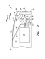
- FIGS. 1 and 2 illustrate one embodiment of a work vehicle 10 in accordance with aspects of the present subject matter.
- FIG. 1 illustrates a side view of the work vehicle 10
- FIG. 2 illustrates a front, perspective view of a hood enclosure 12 of the work vehicle 10.
- the work vehicle 10 illustrated herein is configured as an agricultural tractor
- the work vehicle 10 may generally be configured as any suitable work vehicle known in the art, such as various other agricultural vehicles, earth-moving vehicles, road vehicles, loaders and/or the like.
- the work vehicle 10 generally include a chassis or frame 14 that is supported by a pair rear wheels 16 and a pair of front wheels 18, with the rear wheels 16 and/or front wheels 18 being configured as drive wheels.
- An operator's compartment or cab 20 may be supported along a rear portion of the frame 14 and a hood enclosure 12 may be supported along a front portion of the frame 14.
- the hood enclosure 12 may generally extend between an aft end 22 disposed adjacent to the cab 20 and a forward end 24 disposed at the front of the work vehicle 10 so as to least partially surround and/or cover an engine 26 and a cooling system 28 of the work vehicle 10.
- the hood enclosure 12 may generally include a top wall 30, a first sidewall 32 and a second sidewall 34 extending between its forward and aft ends 24, 22.
- the hood enclosure 12 may include a front wall 36 disposed at its forward end 24.
- the hood enclosure 12 may include a front grille 38 forming all or a portion of the front wall 36 and one or more secondary grilles 40 spaced apart from the front grille 38 in the direction of the aft end 22 of the hood enclosure 12.
- the hood enclosure 12 includes a secondary grille(s) 40 forming at least a portion of the top wall 30.
- the hood enclosure 12 may include one or more secondary grilles 40 forming at least a portion of one or both of the sidewalls 32, 34.
- the hood enclosure 12 includes secondary grilles 40 disposed on both the top wall 30 and the sidewalls 32, 34.
- grille is used to describe any suitable structure that includes a plurality of openings and/or slits for allowing air to enter and/or exit the hood enclosure 12.
- suitable grilles may include, but are not limited to, conventional vehicle grilles, louvers and/or the like and may be configured to have fixed or adjustable grille screens and/or grille bars/slats.
- the hood enclosure 12 may at least partially define one or more compartments 42, 44 for housing the various components disposed at the front of the work vehicle 10.
- the hood enclosure 12 may at least partially define an engine compartment 42 extending from the aft end 22 of the hood enclosure 12.
- the engine compartment 42 may generally be configured to house the engine 26 of the work vehicle 10, as well as any other suitable components (e.g., the transmission and/or the hydraulic system (not shown) of the work vehicle 10).
- the hood enclosure 12 may at least partially define an airflow compartment 44 for housing the various components of the cooling system 28.
- the airflow compartment 44 may be defined at the forward end 24 of the hood enclosure 12 and may extend within the hood enclosure 12 between the front grille 38 and the engine compartment 42.
- the cooling system 28 of the work vehicle 10 may generally include one or more heat exchangers 48 disposed between the front grille 38 and the engine 26.
- the heat exchanger(s) 48 may be disposed directly behind the front grille 38.
- the heat exchanger(s) 48 may be configured to cool the engine fluid(s) and/or the other fluid(s) utilized during operation of the work vehicle 10 by transmitting such fluid(s) through a plurality of tubes having suitable heat transfer features (e.g., cooling fins, rods, coils and/or the like) so that heat is transferred from the fluid(s) to an airflow passing over and across the tubes.
- the heat exchanger(s) 48 may comprise one or more radiators, intercoolers, fuel coolers, transmission fluid coolers, engine oil coolers and/or the like.
- the heat exchangers 48 may generally be disposed within the airflow compartment 44 at any suitable location relative to one another. However, in a particular embodiment of the present subject matter, the heat exchangers 48 may be aligned relative to one another so as to have a generally planar orientation at and/or adjacent to the front grille 38, such as by aligning the heat exchangers 48 in a plane that extends generally parallel to the plane defined by the front grille 38.
- one or more of the heat exchangers 48 may be disposed at and/or adjacent to the secondary grille(s) 40.
- one or more heat exchangers 48 may be disposed at and/or adjacent to the front grille 38, the secondary grille 40 disposed on the top wall 30 and/or the secondary grilles 40 disposed on the sidewalls 32, 34 (one of which is shown).
- the heat exchangers 48 may be separated to allow ambient air to be directed through each heat exchanger 48.
- the cooling system 28 may also include one or more cooling fans 50 for generating an airflow through the heat exchanger(s) 48.
- the cooling fan(s) 50, 52 may be configured to generate a reversible airflow that is directed through the airflow compartment 44 between the front and secondary grilles 38, 40. By providing a reversible airflow through the airflow compartment 44, the cooling performance of the heat exchanger(s) 48 may generally be enhanced.
- the airflow through the airflow compartment 44 may be reversed based on one or more airflow parameters of the work vehicle 10 in order to prevent and/or limit the amount of hot air recirculation within the airflow compartment 44 and/or to otherwise enhance the heat transfer capabilities of the heat exchanger(s) 48.
- airflow parameter refers to any operating parameter of the work vehicle 10 that relates to the temperature of the air at and/or adjacent to the front grille 38 and/or the secondary grille 40 and/or that may otherwise result in a differential between the temperatures at and/or adjacent to the front and secondary grilles 38, 40.
- the blades of the first cooling fan 50 may be configured to have a suitable pitch such that, when the first cooling fan 50 is rotated by the output shaft 54, the cooling fan 50 pulls air into the front grille 38 and through the heat exchanger(s) 48 and pushes the air out the secondary grille 40.
- the second cooling fan 52 may be configured to generate an airflow through the airflow compartment 44 that is directed in a second direction (i.e., from the secondary grille 40 to the front grille 38 and indicated by arrow 58).
- the blades of the second cooling fan 52 may be configured to have a suitable pitch such that, when the second cooling fan 52 is rotated by the output shaft 54, the second cooling fan 52 pulls air into the secondary grille 40 and pushes the air through the heat exchanger(s) 48 and out the front grille 38.
- the first and second cooling fans 50, 52 may be configured to be selectively engaged with and disengaged from the output shaft 54 of the engine 26 to permit each cooling fan 50, 52 to be rotated by the output shaft 54 independent of the other cooling fan 50, 52.
- the first and second cooling fans 50, 52 may be coupled to the output shaft 54 via a coupling device 60.
- the coupling device 60 may comprise any suitable device and/or combination of devices that is capable of permitting the cooling fans 50, 52 to be independently engaged with and disengaged from the output shaft 54.
- the coupling device 60 may comprise one or more electrical clutches and/or gear arrangements configured to independently engage/disengage the cooling fans 50, 52 with/from the output shaft 54
- the coupling device 60 may be communicatively coupled to a controller 62 of the work vehicle 10 to permit the coupling device 60 to automatically engage/disengage the cooling fans 50, 52 with/from the output shaft 54 based on signals transmitted from the controller 62.
- the controller 62 may be configured to transmit a suitable control signal instructing the coupling device 60 to engage the first cooling fan 50 with the output shaft 54 and disengage the second cooling fan 54 from the output shaft 54.
- the controller 62 may be configured to transmit a suitable control signal instructing the coupling device 60 to engage the second cooling fan 52 with the output shaft 54 and disengage the first cooling fan 50 from the output shaft 54.
- the controller 62 may generally comprise any suitable computer and/or other processing unit capable of controlling the operation of the cooling fans 50, 52 (e.g., by controlling the operation of the coupling device 60).
- the controller 62 may include one or more processor(s) and associated memory device(s) configured to perform any number of computer-implemented functions.
- the controller 62 may form all or a potion of the overall control system of the work vehicle 10.
- the controller 62 be configured as a separate controller specifically designed to control the operation of the cooling fans 50, 52.
- the first and second cooling fans 50, 52 need not be coupled coaxially with the output shaft 54.
- the blades of each cooling fan 50, 52 may be mounted onto a separate fan shaft (not shown) extending generally parallel to the output shaft 54.
- the separate fan shaft of each cooling fan 50, 52 may be configured to be selectively engaged with and disengaged from the output shaft 54 via the coupling device 60 (e.g., by using a suitable clutch arrangement, gear arrangement, belt and pulley arrangement and/or the like) to permit the cooling fans 50, 52 to be independently rotated by the output shaft 54.
- the cooling system 28 may only include a single cooling fan 50, 52 driven by the output shaft 54 of the engine 26.
- the rotation of the cooling fan 50, 52 may be reversible to permit such fan 50, 52 to generate airflows in both the first and second directions 56, 58.
- the coupling device 60 may include a suitable clutch and reverse gear arrangement that permits rotation of the cooling fan 50, 52 to be reversed relative to the rotation of the output shaft 54.
- the cooling fan 50, 52 may be configured as a variable pitch fan having blades with adjustable pitches to allow the airflow through the airflow compartment 44 to be reversed without reversing the rotation of the cooling fan 50, 52.
- variable pitch fans are commercially available and are well known in the fan/propeller art.
- the cooling fan(s) 50, 52 may be configured to reverse the direction of the airflow based on the direction of travel of the work vehicle 10.
- the air around the front grille 38 may generally be at the same temperature as the ambient air out in front of the work vehicle 10.
- the controller 62 may be configured to control the operation of the cooling fan(s) 50, 52 (e.g., by engaging the first cooling fan 50 with the output shaft 54) such that the airflow is directed through the airflow compartment 44 in the first direction 56 (i.e., by entering through the front grille 38 and exiting through the secondary grille 40).
- the controller 62 may be configured to control the operation of the cooling fan(s) 50, 52 (e.g., by engaging the second cooling fan 52 with the output shaft 54) such that the airflow is directed through the airflow compartment 44 in the second direction 58 (i.e., by entering through the secondary grille 40 and exiting through the front grille 38) in order to prevent the warmed air flowing around the front grille 38 from being pulled into the airflow compartment 44 and directed past the heat exchangers 48.
- such a configuration may generally prevent and/or limit the amount of hot air recirculation through the airflow compartment 44, thereby improving the heat transfer capabilities of the heat exchanger(s) 28.
- the cooling fan(s) 50, 52 may be configured to reverse the direction of the airflow based on any other suitable airflow parameter of the work vehicle.
- operation of the cooling fan(s) 50, 52 may be controlled based on the direction and/or the speed of the wind flowing around and/or adjacent to the work vehicle 10.
- a suitable wind sensor 68 FIG. 1
- an anemometer and/or the like may be mounted on and/or within a portion of the work vehicle 10 (e.g., on top of the cab 20) to permit wind direction and/or wind speed measurements to be obtained.
- the wind sensor 68 may be communicatively coupled to the controller 62 via a wired or wireless connection to permit signals associated with the sensor measurements to be transmitted to the controller 62, which may then be used to control the operation of the cooling fan(s) 50, 52.
- the controller 62 may be configured to control the cooling fan(s) 50, 52 such that the airflow through the airflow compartment 44 is changed from the forward direction 56 to the reverse direction 58 in the event that the wind speed is greater than the travel speed of the work vehicle 10. As such, recirculation of the hot air from the engine compartment that is carried by the wind to the front of the work vehicle may be avoided.
- operation of the cooling fan(s) 50, 52 may be controlled based on the ambient temperature of the air at and/or adjacent to the work vehicle 10.
- one or more suitable temperature sensors 70, 72 may be mounted on and/or within a portion(s) of the work vehicle 10 to permit air temperature measurements to be obtained.
- a first temperature sensor 70 may be disposed at the front of the work vehicle 10 to obtain temperature measurements of the ambient air located at and/or adjacent to the vehicle's front and a second temperature sensor 72 may be disposed at the rear of the work vehicle 10 to obtain temperature measurements of the ambient air located at and/or adjacent to the vehicle's rear.
- Each sensor 70, 72 may be configured to transmit temperature measurements to the controller 62 via a wired or wireless connection such that the controller 62 may determine the location of the coolest air relative to the work vehicle 10. For instance, if the temperature measurements indicate that the air around the rear of the work vehicle 10 is cooler than the air around the front of the work vehicle 10, the controller 62 may be configured to control the operation of the cooling fan(s) 50, 52 such that the airflow through the airflow compartment 44 is directed in the second direction 58, thereby drawing in air at a more rearward location along the work vehicle 10 (i.e., through the secondary grille 40).
- operation of the cooling fan(s) 50, 52 may be controlled based on any other suitable airflow parameter of the work vehicle 10, such as operating temperatures within the engine compartment 42, debris amounts within the front and/or secondary grilles 38, 40 and/or the like.
- operation of the cooling fan(s) 50, 52 may be based on any number and/or combination of the airflow parameters of the work vehicle 10. For instance, in one embodiment, operation of the cooling fan(s) 50, 52 may be based on a combination of the direction of travel of the work vehicle 10 and the speed and/or direction of the wind.
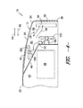
- FIG. 4 a cross-sectional, internal side view of another embodiment of the hood enclosure 12 shown in FIGS. 1 and 2 is illustrated in accordance with aspects of the present subject matter, particularly illustrating another embodiment of the cooling system 28 of the work vehicle 10.
- the cooling fan(s) 150 may be driven by a drive source other than the engine 28, such as a separate drive motor 180.
- the drive motor 180 may be mounted within a portion of the hood enclosure 12 (e.g., within the airflow compartment 44) and may be configured to facilitate rotation of the cooling fan(s) 150.
- the drive motor 180 may comprise a reversible motor (e.g., a reversible electrical motor, a reversible hydraulic motor and/or the like) that is capable of rotating the cooling fan(s) 150 in both clockwise and counter-clockwise directions so that the direction of the airflow through the airflow compartment 44 may be reversed.
- the drive motor 180 may be configured to rotate the cooling fan(s) 150 in a single direction.
- the cooling fan(s) 150 and/or the drive motor 180 may have a similar arrangement to the embodiments described above with reference to FIG.
- differentially pitch cooling fans e.g., the first and second cooling fans 50, 52
- the cooling fan(s) 150 as variable pitch fan(s).
- the drive motor 180 may be communicatively coupled to a controller 62 via a wired or wireless connection to allow the operation of the cooling fan(s) 150 to be controlled.
- the controller 62 may be configured to control the operation of the drive motor 180 and/or the cooling fan(s) 150 based on one or more airflow parameters of the work vehicle 10 in order to maximize the efficiency of the heat exchanger(s) 48.
- the work vehicle 10 may also include one or more auxiliary fans 182 to further enhance the airflow through the airflow compartment 44.
- an auxiliary fan(s) 182 may be disposed at and/or adjacent to the secondary grille 40 to provide an additional source for drawing air through and/or expelling air out of the secondary grille 40, depending on the desired direction of the airflow.
- the auxiliary fan(s) 182 may be driven by an auxiliary drive motor 184 (configured the same as or similar to drive motor 180 described above) and may be communicatively coupled to the controller 62 to allow control of its operation.
- an auxiliary fan(s) 182 may be disposed at any other suitable location with the airflow compartment 44, such as by being located between the front grille 38 and the heat exchanger(s) 48, and may be driven by any suitable drive source, such as another auxiliary drive motor 184 or the output shaft 54 of the engine 26.
- the present subject matter is also directed to a method for improving the cooling performance of the heat exchanger(s) 48 of a work vehicle 10.
- the method may include generating an airflow with one or more cooling fan(s) 50, 52, 150 that is directed through the heat exchanger(s) 48 between the front and secondary grilles 38, 40 and reversing the direction of the airflow through the heat exchanger(s) 48 based on an airflow parameter of the work vehicle 10.
- the controller 62 of the work vehicle 10 may be configured to control the operation of the cooling fan(s) 50, 52, 150 such that the airflow through the airflow compartment 44 is directed in the first direction 56 when the work vehicle 10 is travelling in the engine-forward direction 64 and is directed in the second direction 58 when the work vehicle 10 is travelling in the cab-forward direction 66.
- the direction of the airflow through the airflow compartment 44 may be controlled so as to prevent and/or limit the amount of hot air recirculation, thereby enhancing the overall performance of the heat exchanger(s) 48.
- one or more of the components of the work vehicle 10 described herein may form all or part of a kit (e.g., a retro-fit and/or field kit) for retro-fitting and/or modifying existing and/or future work vehicles.
- a kit e.g., a retro-fit and/or field kit
- the cooling fan(s) 50, 52, 150, drive motor(s) 180, 184, coupling device 60, controller 62 and/or grilles 38, 40 may form all or part of a kit to be used with existing and/or future work vehicles.
Landscapes
- Engineering & Computer Science (AREA)
- Chemical & Material Sciences (AREA)
- Combustion & Propulsion (AREA)
- Transportation (AREA)
- Mechanical Engineering (AREA)
- Cooling, Air Intake And Gas Exhaust, And Fuel Tank Arrangements In Propulsion Units (AREA)
Applications Claiming Priority (1)
| Application Number | Priority Date | Filing Date | Title |
|---|---|---|---|
| US201161570051P | 2011-12-13 | 2011-12-13 |
Publications (2)
| Publication Number | Publication Date |
|---|---|
| EP2604460A1 true EP2604460A1 (fr) | 2013-06-19 |
| EP2604460B1 EP2604460B1 (fr) | 2016-04-13 |
Family
ID=46603764
Family Applications (1)
| Application Number | Title | Priority Date | Filing Date |
|---|---|---|---|
| EP12179216.2A Active EP2604460B1 (fr) | 2011-12-13 | 2012-08-03 | Véhicule de travail ayant un système de refroidissement avec un écoulement d'air réversible |
Country Status (2)
| Country | Link |
|---|---|
| US (1) | US9452674B2 (fr) |
| EP (1) | EP2604460B1 (fr) |
Cited By (3)
| Publication number | Priority date | Publication date | Assignee | Title |
|---|---|---|---|---|
| EP2875979A1 (fr) * | 2013-11-20 | 2015-05-27 | Valeo Klimasysteme GmbH | Module frontal d'un véhicule |
| WO2018210388A1 (fr) * | 2017-05-16 | 2018-11-22 | Nilfisk A/S | Refroidissement de carter à moteur de propulsion pour véhicule utilitaire |
| EP3696002A1 (fr) * | 2019-02-13 | 2020-08-19 | CLAAS Tractor S.A.S. | Machine de travail agricole pourvue de groupe de radiateur et procédé de contrôle |
Families Citing this family (13)
| Publication number | Priority date | Publication date | Assignee | Title |
|---|---|---|---|---|
| US9579968B2 (en) * | 2012-11-30 | 2017-02-28 | Cnh Industrial America Llc | One-way vented screen assembly for a work vehicle |
| EP2792795B1 (fr) * | 2013-02-22 | 2015-04-08 | Komatsu Ltd. | Chargeur à roues |
| JP6126954B2 (ja) * | 2013-09-11 | 2017-05-10 | 本田技研工業株式会社 | 鞍乗型車両 |
| US10059192B2 (en) | 2015-06-17 | 2018-08-28 | Cnh Industrial America Llc | System and method for adjusting air flow in an engine compartment of an off-road vehicle |
| USD765740S1 (en) | 2015-06-17 | 2016-09-06 | Cnh Industrial America Llc | Engine hood of an agricultural vehicle |
| USD766340S1 (en) | 2015-06-17 | 2016-09-13 | Cnh Industrial America Llc | Engine hood of an agricultural vehicle |
| USD753195S1 (en) | 2015-06-17 | 2016-04-05 | Cnh Industrial America Llc | Engine hood of an agricultural vehicle |
| CN110126614A (zh) * | 2018-02-08 | 2019-08-16 | 宝沃汽车(中国)有限公司 | 散热方法、散热系统及车辆 |
| EP3556593B1 (fr) * | 2018-04-20 | 2022-01-19 | Wacker Neuson Linz GmbH | Véhicule de travail doté d'un dispositif déflecteur d'air de refroidissement côté sortie |
| CN110588328A (zh) * | 2019-10-10 | 2019-12-20 | 江苏徐工工程机械研究院有限公司 | 一种动力舱、工程车辆及动力舱的温度控制方法 |
| US11560826B2 (en) * | 2020-08-15 | 2023-01-24 | Kubota Corporation | Working machine |
| US11864483B2 (en) * | 2020-10-09 | 2024-01-09 | Deere & Company | Predictive map generation and control system |
| GB202213795D0 (en) * | 2022-09-21 | 2022-11-02 | Agco Int Gmbh | Agricultural vehicle with cooling system |
Citations (7)
| Publication number | Priority date | Publication date | Assignee | Title |
|---|---|---|---|---|
| US3095766A (en) * | 1961-03-31 | 1963-07-02 | Henry C Cox | Fan reversing mechanism |
| EP0323211A2 (fr) * | 1987-12-28 | 1989-07-05 | Honda Giken Kogyo Kabushiki Kaisha | Système de commande de refroidissement pour salle de machines |
| EP0646485A2 (fr) * | 1993-09-30 | 1995-04-05 | Caterpillar Inc. | Système de refroidissement à conduits indépendantes |
| DE19959893A1 (de) * | 1999-12-11 | 2001-06-28 | Haegele Gmbh | Angetriebenes Lüfterrad, insbesondere für Brennkraftmaschinen |
| US20020029912A1 (en) * | 2000-05-09 | 2002-03-14 | Mackelvie Winston | Bi-directional automotive cooling fan |
| EP1950074A1 (fr) * | 2007-01-26 | 2008-07-30 | Maschinenfabrik Bernhard Krone GmbH | Machine agricole automobile |
| EP2272703A1 (fr) * | 2009-06-30 | 2011-01-12 | Agco SA | Ensemble de refroidissement de tracteur agricole |
Family Cites Families (13)
| Publication number | Priority date | Publication date | Assignee | Title |
|---|---|---|---|---|
| US2729202A (en) * | 1951-03-23 | 1956-01-03 | Elmore J Sanders | Fluid circulation systems |
| US2703075A (en) * | 1951-03-23 | 1955-03-01 | Elmore J Sanders | Fluid circulating apparatus |
| US3868992A (en) * | 1973-02-20 | 1975-03-04 | Caterpillar Tractor Co | Gross flow cooling system |
| DE2437995A1 (de) * | 1974-08-07 | 1976-02-26 | Int Harvester Co | Kraftfahrzeug |
| US4081050A (en) * | 1977-02-02 | 1978-03-28 | International Harvester Company | Front engine tractor having transverse midship mounted heat exchanger |
| US4086976A (en) * | 1977-02-02 | 1978-05-02 | International Harvester Company | Isolated clean air chamber and engine compartment in a tractor vehicle |
| US4371047A (en) * | 1980-04-02 | 1983-02-01 | International Harvester Company | Agricultural tractor having reverse air flow cooling |
| US4341277A (en) * | 1980-06-23 | 1982-07-27 | Fiat-Allis Construction Machinery, Inc. | Perforated hood with air scoop |
| US4454926A (en) * | 1982-03-08 | 1984-06-19 | International Harvester Co. | Air intake on a tractor engine hood |
| ITTO20030127A1 (it) * | 2003-02-21 | 2004-08-22 | Same Deutz Fahr Group Spa | Sistema di raffreddamento per una macchina agricola. |
| US7051786B2 (en) * | 2003-07-11 | 2006-05-30 | Deere & Company | Vertical airflow engine cooling system |
| US7325518B2 (en) * | 2005-09-08 | 2008-02-05 | Deere & Company | Vehicle parallel cooling system |
| US8167067B2 (en) * | 2009-07-16 | 2012-05-01 | Agco Corporation | Agricultural vehicle emission aftertreatment device utilizing heat exchanger ventilation |
-
2012
- 2012-08-03 EP EP12179216.2A patent/EP2604460B1/fr active Active
- 2012-12-11 US US13/711,153 patent/US9452674B2/en active Active
Patent Citations (7)
| Publication number | Priority date | Publication date | Assignee | Title |
|---|---|---|---|---|
| US3095766A (en) * | 1961-03-31 | 1963-07-02 | Henry C Cox | Fan reversing mechanism |
| EP0323211A2 (fr) * | 1987-12-28 | 1989-07-05 | Honda Giken Kogyo Kabushiki Kaisha | Système de commande de refroidissement pour salle de machines |
| EP0646485A2 (fr) * | 1993-09-30 | 1995-04-05 | Caterpillar Inc. | Système de refroidissement à conduits indépendantes |
| DE19959893A1 (de) * | 1999-12-11 | 2001-06-28 | Haegele Gmbh | Angetriebenes Lüfterrad, insbesondere für Brennkraftmaschinen |
| US20020029912A1 (en) * | 2000-05-09 | 2002-03-14 | Mackelvie Winston | Bi-directional automotive cooling fan |
| EP1950074A1 (fr) * | 2007-01-26 | 2008-07-30 | Maschinenfabrik Bernhard Krone GmbH | Machine agricole automobile |
| EP2272703A1 (fr) * | 2009-06-30 | 2011-01-12 | Agco SA | Ensemble de refroidissement de tracteur agricole |
Cited By (3)
| Publication number | Priority date | Publication date | Assignee | Title |
|---|---|---|---|---|
| EP2875979A1 (fr) * | 2013-11-20 | 2015-05-27 | Valeo Klimasysteme GmbH | Module frontal d'un véhicule |
| WO2018210388A1 (fr) * | 2017-05-16 | 2018-11-22 | Nilfisk A/S | Refroidissement de carter à moteur de propulsion pour véhicule utilitaire |
| EP3696002A1 (fr) * | 2019-02-13 | 2020-08-19 | CLAAS Tractor S.A.S. | Machine de travail agricole pourvue de groupe de radiateur et procédé de contrôle |
Also Published As
| Publication number | Publication date |
|---|---|
| US9452674B2 (en) | 2016-09-27 |
| EP2604460B1 (fr) | 2016-04-13 |
| US20130146377A1 (en) | 2013-06-13 |
Similar Documents
| Publication | Publication Date | Title |
|---|---|---|
| US9452674B2 (en) | Work vehicle having a cooling system with a reversible airflow | |
| US9579968B2 (en) | One-way vented screen assembly for a work vehicle | |
| US8739744B2 (en) | Compound shutter system | |
| JP5067502B2 (ja) | 冷却風導入構造 | |
| AU2012202045B2 (en) | Tractor hood airflow system | |
| RU2460652C2 (ru) | Система управления воздушным потоком для регулирования температуры в подкапотном пространстве грузового автомобиля большой грузоподъемности | |
| JP5807486B2 (ja) | グリルシャッタ装置 | |
| US7051786B2 (en) | Vertical airflow engine cooling system | |
| US4186693A (en) | Water-cooled internal combustion engine for motor vehicles, particularly a diesel engine | |
| US20120097464A1 (en) | Control of a shutter via bi-directional communication using a single wire | |
| US20120097465A1 (en) | System and method for controlling a shutter in a vehicle via a cooling fan duty-cycle | |
| EP2733342B1 (fr) | Agencement de filtre à air pour véhicule de travail | |
| US20130264047A1 (en) | Shielded positive stops for an active shutter | |
| US10166859B1 (en) | Active underbody arrangement for a vehicle | |
| US20100326755A1 (en) | Agricultural Tractor Cooling Package | |
| JP5983312B2 (ja) | 車両の冷却システム | |
| US11602985B2 (en) | Continuous cooling assembly | |
| EP3230612B1 (fr) | Ensemble d'entraînement de ventilateur | |
| EP3271674B1 (fr) | Système de refroidissement | |
| JP5314490B2 (ja) | 車両用ラジエータのシール構造 | |
| JP4542410B2 (ja) | 農用トラクタ | |
| US20200398643A1 (en) | Vehicle cooling mechanism | |
| JP7043251B2 (ja) | ハイブリッド車 | |
| JP2017030521A (ja) | ラジエータ及びこれを備えた作業車両 | |
| JP3225200B2 (ja) | 鉄道車両用動力装置の冷却装置 |
Legal Events
| Date | Code | Title | Description |
|---|---|---|---|
| PUAI | Public reference made under article 153(3) epc to a published international application that has entered the european phase |
Free format text: ORIGINAL CODE: 0009012 |
|
| AK | Designated contracting states |
Kind code of ref document: A1 Designated state(s): AL AT BE BG CH CY CZ DE DK EE ES FI FR GB GR HR HU IE IS IT LI LT LU LV MC MK MT NL NO PL PT RO RS SE SI SK SM TR |
|
| AX | Request for extension of the european patent |
Extension state: BA ME |
|
| 17P | Request for examination filed |
Effective date: 20131219 |
|
| RBV | Designated contracting states (corrected) |
Designated state(s): AL AT BE BG CH CY CZ DE DK EE ES FI FR GB GR HR HU IE IS IT LI LT LU LV MC MK MT NL NO PL PT RO RS SE SI SK SM TR |
|
| RAP1 | Party data changed (applicant data changed or rights of an application transferred) |
Owner name: CNH INDUSTRIAL ITALIA S.P.A. |
|
| 17Q | First examination report despatched |
Effective date: 20141020 |
|
| GRAP | Despatch of communication of intention to grant a patent |
Free format text: ORIGINAL CODE: EPIDOSNIGR1 |
|
| INTG | Intention to grant announced |
Effective date: 20151022 |
|
| GRAS | Grant fee paid |
Free format text: ORIGINAL CODE: EPIDOSNIGR3 |
|
| GRAA | (expected) grant |
Free format text: ORIGINAL CODE: 0009210 |
|
| AK | Designated contracting states |
Kind code of ref document: B1 Designated state(s): AL AT BE BG CH CY CZ DE DK EE ES FI FR GB GR HR HU IE IS IT LI LT LU LV MC MK MT NL NO PL PT RO RS SE SI SK SM TR |
|
| REG | Reference to a national code |
Ref country code: GB Ref legal event code: FG4D |
|
| REG | Reference to a national code |
Ref country code: AT Ref legal event code: REF Ref document number: 789717 Country of ref document: AT Kind code of ref document: T Effective date: 20160415 Ref country code: CH Ref legal event code: EP |
|
| REG | Reference to a national code |
Ref country code: DE Ref legal event code: R084 Ref document number: 602012016981 Country of ref document: DE |
|
| REG | Reference to a national code |
Ref country code: IE Ref legal event code: FG4D |
|
| REG | Reference to a national code |
Ref country code: DE Ref legal event code: R096 Ref document number: 602012016981 Country of ref document: DE |
|
| REG | Reference to a national code |
Ref country code: GB Ref legal event code: 746 Effective date: 20160519 |
|
| REG | Reference to a national code |
Ref country code: FR Ref legal event code: PLFP Year of fee payment: 5 |
|
| REG | Reference to a national code |
Ref country code: LT Ref legal event code: MG4D |
|
| REG | Reference to a national code |
Ref country code: AT Ref legal event code: MK05 Ref document number: 789717 Country of ref document: AT Kind code of ref document: T Effective date: 20160413 |
|
| REG | Reference to a national code |
Ref country code: NL Ref legal event code: MP Effective date: 20160413 |
|
| PG25 | Lapsed in a contracting state [announced via postgrant information from national office to epo] |
Ref country code: LT Free format text: LAPSE BECAUSE OF FAILURE TO SUBMIT A TRANSLATION OF THE DESCRIPTION OR TO PAY THE FEE WITHIN THE PRESCRIBED TIME-LIMIT Effective date: 20160413 Ref country code: NO Free format text: LAPSE BECAUSE OF FAILURE TO SUBMIT A TRANSLATION OF THE DESCRIPTION OR TO PAY THE FEE WITHIN THE PRESCRIBED TIME-LIMIT Effective date: 20160713 Ref country code: FI Free format text: LAPSE BECAUSE OF FAILURE TO SUBMIT A TRANSLATION OF THE DESCRIPTION OR TO PAY THE FEE WITHIN THE PRESCRIBED TIME-LIMIT Effective date: 20160413 Ref country code: PL Free format text: LAPSE BECAUSE OF FAILURE TO SUBMIT A TRANSLATION OF THE DESCRIPTION OR TO PAY THE FEE WITHIN THE PRESCRIBED TIME-LIMIT Effective date: 20160413 Ref country code: NL Free format text: LAPSE BECAUSE OF FAILURE TO SUBMIT A TRANSLATION OF THE DESCRIPTION OR TO PAY THE FEE WITHIN THE PRESCRIBED TIME-LIMIT Effective date: 20160413 |
|
| PG25 | Lapsed in a contracting state [announced via postgrant information from national office to epo] |
Ref country code: RS Free format text: LAPSE BECAUSE OF FAILURE TO SUBMIT A TRANSLATION OF THE DESCRIPTION OR TO PAY THE FEE WITHIN THE PRESCRIBED TIME-LIMIT Effective date: 20160413 Ref country code: ES Free format text: LAPSE BECAUSE OF FAILURE TO SUBMIT A TRANSLATION OF THE DESCRIPTION OR TO PAY THE FEE WITHIN THE PRESCRIBED TIME-LIMIT Effective date: 20160413 Ref country code: LV Free format text: LAPSE BECAUSE OF FAILURE TO SUBMIT A TRANSLATION OF THE DESCRIPTION OR TO PAY THE FEE WITHIN THE PRESCRIBED TIME-LIMIT Effective date: 20160413 Ref country code: HR Free format text: LAPSE BECAUSE OF FAILURE TO SUBMIT A TRANSLATION OF THE DESCRIPTION OR TO PAY THE FEE WITHIN THE PRESCRIBED TIME-LIMIT Effective date: 20160413 Ref country code: GR Free format text: LAPSE BECAUSE OF FAILURE TO SUBMIT A TRANSLATION OF THE DESCRIPTION OR TO PAY THE FEE WITHIN THE PRESCRIBED TIME-LIMIT Effective date: 20160714 Ref country code: AT Free format text: LAPSE BECAUSE OF FAILURE TO SUBMIT A TRANSLATION OF THE DESCRIPTION OR TO PAY THE FEE WITHIN THE PRESCRIBED TIME-LIMIT Effective date: 20160413 Ref country code: SE Free format text: LAPSE BECAUSE OF FAILURE TO SUBMIT A TRANSLATION OF THE DESCRIPTION OR TO PAY THE FEE WITHIN THE PRESCRIBED TIME-LIMIT Effective date: 20160413 Ref country code: PT Free format text: LAPSE BECAUSE OF FAILURE TO SUBMIT A TRANSLATION OF THE DESCRIPTION OR TO PAY THE FEE WITHIN THE PRESCRIBED TIME-LIMIT Effective date: 20160816 |
|
| PG25 | Lapsed in a contracting state [announced via postgrant information from national office to epo] |
Ref country code: BE Free format text: LAPSE BECAUSE OF FAILURE TO SUBMIT A TRANSLATION OF THE DESCRIPTION OR TO PAY THE FEE WITHIN THE PRESCRIBED TIME-LIMIT Effective date: 20160413 |
|
| REG | Reference to a national code |
Ref country code: DE Ref legal event code: R097 Ref document number: 602012016981 Country of ref document: DE |
|
| PG25 | Lapsed in a contracting state [announced via postgrant information from national office to epo] |
Ref country code: CZ Free format text: LAPSE BECAUSE OF FAILURE TO SUBMIT A TRANSLATION OF THE DESCRIPTION OR TO PAY THE FEE WITHIN THE PRESCRIBED TIME-LIMIT Effective date: 20160413 Ref country code: EE Free format text: LAPSE BECAUSE OF FAILURE TO SUBMIT A TRANSLATION OF THE DESCRIPTION OR TO PAY THE FEE WITHIN THE PRESCRIBED TIME-LIMIT Effective date: 20160413 Ref country code: SK Free format text: LAPSE BECAUSE OF FAILURE TO SUBMIT A TRANSLATION OF THE DESCRIPTION OR TO PAY THE FEE WITHIN THE PRESCRIBED TIME-LIMIT Effective date: 20160413 Ref country code: DK Free format text: LAPSE BECAUSE OF FAILURE TO SUBMIT A TRANSLATION OF THE DESCRIPTION OR TO PAY THE FEE WITHIN THE PRESCRIBED TIME-LIMIT Effective date: 20160413 Ref country code: RO Free format text: LAPSE BECAUSE OF FAILURE TO SUBMIT A TRANSLATION OF THE DESCRIPTION OR TO PAY THE FEE WITHIN THE PRESCRIBED TIME-LIMIT Effective date: 20160413 |
|
| PLBE | No opposition filed within time limit |
Free format text: ORIGINAL CODE: 0009261 |
|
| STAA | Information on the status of an ep patent application or granted ep patent |
Free format text: STATUS: NO OPPOSITION FILED WITHIN TIME LIMIT |
|
| PG25 | Lapsed in a contracting state [announced via postgrant information from national office to epo] |
Ref country code: SM Free format text: LAPSE BECAUSE OF FAILURE TO SUBMIT A TRANSLATION OF THE DESCRIPTION OR TO PAY THE FEE WITHIN THE PRESCRIBED TIME-LIMIT Effective date: 20160413 |
|
| 26N | No opposition filed |
Effective date: 20170116 |
|
| PG25 | Lapsed in a contracting state [announced via postgrant information from national office to epo] |
Ref country code: MC Free format text: LAPSE BECAUSE OF FAILURE TO SUBMIT A TRANSLATION OF THE DESCRIPTION OR TO PAY THE FEE WITHIN THE PRESCRIBED TIME-LIMIT Effective date: 20160413 |
|
| REG | Reference to a national code |
Ref country code: CH Ref legal event code: PL |
|
| PG25 | Lapsed in a contracting state [announced via postgrant information from national office to epo] |
Ref country code: CH Free format text: LAPSE BECAUSE OF NON-PAYMENT OF DUE FEES Effective date: 20160831 Ref country code: LI Free format text: LAPSE BECAUSE OF NON-PAYMENT OF DUE FEES Effective date: 20160831 |
|
| PG25 | Lapsed in a contracting state [announced via postgrant information from national office to epo] |
Ref country code: SI Free format text: LAPSE BECAUSE OF FAILURE TO SUBMIT A TRANSLATION OF THE DESCRIPTION OR TO PAY THE FEE WITHIN THE PRESCRIBED TIME-LIMIT Effective date: 20160413 |
|
| REG | Reference to a national code |
Ref country code: IE Ref legal event code: MM4A |
|
| REG | Reference to a national code |
Ref country code: FR Ref legal event code: PLFP Year of fee payment: 6 |
|
| PG25 | Lapsed in a contracting state [announced via postgrant information from national office to epo] |
Ref country code: IE Free format text: LAPSE BECAUSE OF NON-PAYMENT OF DUE FEES Effective date: 20160803 |
|
| PG25 | Lapsed in a contracting state [announced via postgrant information from national office to epo] |
Ref country code: LU Free format text: LAPSE BECAUSE OF NON-PAYMENT OF DUE FEES Effective date: 20160803 |
|
| PG25 | Lapsed in a contracting state [announced via postgrant information from national office to epo] |
Ref country code: CY Free format text: LAPSE BECAUSE OF FAILURE TO SUBMIT A TRANSLATION OF THE DESCRIPTION OR TO PAY THE FEE WITHIN THE PRESCRIBED TIME-LIMIT Effective date: 20160413 Ref country code: HU Free format text: LAPSE BECAUSE OF FAILURE TO SUBMIT A TRANSLATION OF THE DESCRIPTION OR TO PAY THE FEE WITHIN THE PRESCRIBED TIME-LIMIT; INVALID AB INITIO Effective date: 20120803 |
|
| PG25 | Lapsed in a contracting state [announced via postgrant information from national office to epo] |
Ref country code: IS Free format text: LAPSE BECAUSE OF FAILURE TO SUBMIT A TRANSLATION OF THE DESCRIPTION OR TO PAY THE FEE WITHIN THE PRESCRIBED TIME-LIMIT Effective date: 20160413 Ref country code: MK Free format text: LAPSE BECAUSE OF FAILURE TO SUBMIT A TRANSLATION OF THE DESCRIPTION OR TO PAY THE FEE WITHIN THE PRESCRIBED TIME-LIMIT Effective date: 20160413 Ref country code: TR Free format text: LAPSE BECAUSE OF FAILURE TO SUBMIT A TRANSLATION OF THE DESCRIPTION OR TO PAY THE FEE WITHIN THE PRESCRIBED TIME-LIMIT Effective date: 20160413 Ref country code: MT Free format text: LAPSE BECAUSE OF NON-PAYMENT OF DUE FEES Effective date: 20160831 |
|
| REG | Reference to a national code |
Ref country code: FR Ref legal event code: PLFP Year of fee payment: 7 |
|
| PG25 | Lapsed in a contracting state [announced via postgrant information from national office to epo] |
Ref country code: BG Free format text: LAPSE BECAUSE OF FAILURE TO SUBMIT A TRANSLATION OF THE DESCRIPTION OR TO PAY THE FEE WITHIN THE PRESCRIBED TIME-LIMIT Effective date: 20160413 |
|
| PG25 | Lapsed in a contracting state [announced via postgrant information from national office to epo] |
Ref country code: AL Free format text: LAPSE BECAUSE OF FAILURE TO SUBMIT A TRANSLATION OF THE DESCRIPTION OR TO PAY THE FEE WITHIN THE PRESCRIBED TIME-LIMIT Effective date: 20160413 |
|
| REG | Reference to a national code |
Ref country code: DE Ref legal event code: R082 Ref document number: 602012016981 Country of ref document: DE Representative=s name: MEISSNER BOLTE PATENTANWAELTE RECHTSANWAELTE P, DE |
|
| PGFP | Annual fee paid to national office [announced via postgrant information from national office to epo] |
Ref country code: IT Payment date: 20230714 Year of fee payment: 12 Ref country code: GB Payment date: 20230824 Year of fee payment: 12 |
|
| PGFP | Annual fee paid to national office [announced via postgrant information from national office to epo] |
Ref country code: FR Payment date: 20230824 Year of fee payment: 12 Ref country code: DE Payment date: 20230831 Year of fee payment: 12 |