EP2603838B1 - Tap sensitive alarm clock - Google Patents
Tap sensitive alarm clock Download PDFInfo
- Publication number
- EP2603838B1 EP2603838B1 EP11754502.0A EP11754502A EP2603838B1 EP 2603838 B1 EP2603838 B1 EP 2603838B1 EP 11754502 A EP11754502 A EP 11754502A EP 2603838 B1 EP2603838 B1 EP 2603838B1
- Authority
- EP
- European Patent Office
- Prior art keywords
- filter
- alarm clock
- sound
- vibration sensor
- sensor
- Prior art date
- Legal status (The legal status is an assumption and is not a legal conclusion. Google has not performed a legal analysis and makes no representation as to the accuracy of the status listed.)
- Active
Links
Images


Classifications
-
- G—PHYSICS
- G04—HOROLOGY
- G04G—ELECTRONIC TIME-PIECES
- G04G21/00—Input or output devices integrated in time-pieces
- G04G21/08—Touch switches specially adapted for time-pieces
-
- G—PHYSICS
- G04—HOROLOGY
- G04G—ELECTRONIC TIME-PIECES
- G04G13/00—Producing acoustic time signals
- G04G13/02—Producing acoustic time signals at preselected times, e.g. alarm clocks
- G04G13/021—Details
-
- G—PHYSICS
- G04—HOROLOGY
- G04G—ELECTRONIC TIME-PIECES
- G04G13/00—Producing acoustic time signals
- G04G13/02—Producing acoustic time signals at preselected times, e.g. alarm clocks
- G04G13/021—Details
- G04G13/023—Adjusting the duration or amplitude of signals
-
- G—PHYSICS
- G04—HOROLOGY
- G04G—ELECTRONIC TIME-PIECES
- G04G13/00—Producing acoustic time signals
- G04G13/02—Producing acoustic time signals at preselected times, e.g. alarm clocks
- G04G13/028—Producing acoustic time signals at preselected times, e.g. alarm clocks combined with a radio
Definitions
- the invention relates to a tap sensitive alarm clock, comprising a housing, a vibration sensor mechanically coupled to the housing for receiving a shock due to a user tapping the housing, and a control circuit coupled to the vibration sensor for controlling a function of the alarm clock.
- Document EP 1 833 103 describes a shock-activated switch device, which comprises a piezoelectric buzzer having a body for receiving a mechanical shock and a terminal for outputting an electrical output signal when the body receives a mechanical shock.
- the shock is provided by a user tapping the housing of the device.
- An output circuit is connected to the terminal for converting the output signal into a logic signal for controlling an electronic circuit to execute a specific programmable function, such as alarm snooze.
- EP 1855170 A2 as well as US 4078376 A show tap sensitive alarm clocks according to the preamble of claim 1.
- a tap sensitive alarm clock like the above shock sensitive device, has a vibration sensor, but may also have an audio unit for generating a sound, such as a buzzer or a loudspeaker. It appeared that the tapping function of such a tap sensitive alarm clock having an audio unit is not reliable, for example, in that the snooze function is sometimes activated unintentionally.
- the alarm clock as described in the opening paragraph comprises an audio unit coupled to an audio circuit for generating sound, and a filter coupled to the vibration sensor and the control circuit, the filter having a filter curve matched to filter frequency components that are present in the sound, so that only frequency components caused by the mechanical shock acting on the vibration sensor are passed to the control circuit.
- the measures have the effect that the sensitivity of the tap function to mechanical shock is enhanced by the filter.
- the filter curve is made to block frequencies occurring in the sound.
- the filter filters frequency components that are present in the sound, so only frequency components caused by the mechanical shock acting on the vibration sensor are passed to the control circuit.
- the sensitivity to frequency components caused by said tapping may be increased to a required level without increasing the risk of accidental activation by the sound.
- the sound when produced, will not trigger the control circuit to activate the respective function of the alarm clock, for example a snooze function of an alarm clock, while frequency components of the shock outside the frequency band of the audio unit are passed by the filter and will contribute to triggering the function.
- Existing shock sensors may be activated by mechanical shocks caused by tapping a housing of an alarm clock.
- the existing sensors may be made to be sensitive to a frequency range caused by such shocks.
- a frequency range i.e. inherent to a sensor or a shock to be detected, may have a substantial overlap with the frequency range of sound produced by commonly used audio units in consumer devices, e.g. a loudspeaker in the alarm clock.
- the sensitivity of such a sensor may be limited to a selected range of frequencies occurring due to tapping, while a part of the range that overlaps is excluded.
- the frequency components that remain, i.e. that are passed via the filter are surprisingly still quite sufficient for detecting said tapping. So said selected range is matched to the audio frequency range of the audio unit that is used in the alarm clock. For example, in many applications the audio frequency range does not have low-frequency components, while sufficient low-frequency components do occur due to tapping. Non-overlapping ranges for sound and for detecting tapping can be practically found, and the filter curve is matched to distinguish between said tapping and the sound.
- the filter is a low-pass filter.
- the filter curve of the low-pass filter is easily matched to block the sound frequency range by selecting an appropriate corner frequency. Frequencies above the corner frequency are blocked, i.e. attenuated increasingly with increasing frequency above the corner frequency.
- the low-pass filter may be combined with a high-pass filter having a high-pass corner frequency below the low-pass corner frequency of the low-pass filter, the combined filter also being called a band-pass filter.
- a practical value for the low-pass corner frequency is between 50 Hz and 200 Hz, e.g. 100 Hz. This has the advantage that sound frequencies are effectively blocked, while the frequency range to which the sensor responds is maximized without overlapping the audio range.
- the vibration sensor is arranged for generating an electrical signal that is coupled to the filter, and the filter is arranged for processing the electrical signal.
- the filter has an adjustable amplification. This has the advantage that the sensitivity can be adjusted, e.g. to the environment or noise level of the alarm clock.
- the filter is arranged for adjusting the amplification in dependence on the level of the sound.
- the disturbance of the sound is reduced when the sound level is high, while the sensor is more sensitive when the sound level is low.
- the audio circuit comprises a high-pass filter having a high-pass filter curve to control the frequencies occurring in the sound. This has the advantage that the contents of sound are controlled so that fewer low-frequency components are generated.
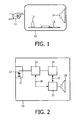
- FIG. 1 shows a tap sensitive alarm clock.
- the alarm clock has a housing 10.
- a user may tap on the housing to activate a function of the alarm clock, as indicated by a user's hand 11, in any appropriate way (slamming, banging, knocking, etc).
- a vibration sensor 12 is mechanically coupled to the housing, e.g. by locating the sensor on the inside against a wall or against an inner element of the housing.
- the sensor is located on an electronic circuit board 13 that is mechanically attached to the housing.
- the function of the electronic board according to the invention is discussed in detail with reference to Figure 2 , and may further comprise any known function for an alarm clock operated by a human user.
- the device further has an audio output element such as a loudspeaker 14 or a buzzer.
- the audio unit is connected to an audio circuit, e.g. also located on the electronic circuit board 13.
- At least one function of the device is activated based on the vibration sensor detecting said mechanical shock due to the tapping action on the housing, e.g. a snooze function or a function to switch to a different sound, or to a different radio station.
- Alarm clocks generally have a 'snooze' function. At the set alarm time, when the alarm sounds, the user can activate this snooze function to silence the alarm clock for a time period, thereby delaying the alarm and enabling a further time of snoozing in bed. This time period is generally in the order of 5 to 10 minutes.
- a sensor is used to detect a 'tap' anywhere on the product. This is accomplished by building into the product a vibration sensor or an accelerometer.
- an alarm clock also contains a sound generating function, for the alarm and/or for rendering music from e.g. a radio. The vibrations generated from this sound source can interfere with the detection of user taps on the product.
- the tap sensor needs to be mechanically connected to the outside of the product, by nature of its function. It is not practicable to disconnect the sound generating function from the housing, as any speaker driver needs the mass of the product or sound box assembly to maintain output quality and volume.
- the electronic circuit 13 is provided with a filter, and/or the sensor is mechanically arranged to the filter.
- the filter has a filter curve that is matched to be complementary to the frequency range of the audio unit.
- a small speaker is used. Due to its small size this speaker is not able to generate a high sound volume at low frequencies.
- a tap against the alarm clock generates a signal inter alia containing lower frequencies than the speaker can produce. By filtering out the high frequencies from the tap sensor signal the remaining signal will only contain tap information.
- FIG. 2 shows a tap sensitive alarm clock having a filter.
- the alarm clock has a housing 20, on which a user may tap to activate a function of the alarm clock.
- a vibration sensor 22 is mechanically coupled to the housing, e.g. by locating the sensor at a sensor mount 21 connected to, or being part of, the housing.
- the sensor is coupled to an electronic circuit, in particular to a filter 23.
- the vibration sensor generates an electrical signal that is coupled to the filter, and the filter is arranged for processing the electrical signal.
- the output of the filter is coupled to a control circuit 24, which detects the filtered signal from the vibration sensor and activates a function of the alarm clock as indicated by arrow 27.
- the control circuit may also provide a signal to an external interface for controlling an external function.
- the alarm clock further comprises an audio circuit 25, e.g. an MP3 player, a clock and/or a radio circuit.
- the alarm clock further has an audio output unit 26 such as a loudspeaker.
- the audio unit is connected to the audio circuit.
- Figure 3 shows a filter curve.
- the Figure shows a graph 30 of frequency versus amplitude for sound and mechanical shock.
- a first curve 33 shows the frequencies occurring in the sound, or the speaker bandwidth. It is noted that frequencies below a boundary 34 of 100 Hz do not occur, i.e. levels of such frequencies are below a predetermined low level.
- a second curve 32 shows frequencies in an unfiltered tap sensor signal. It is to be noted that the tap frequency range has a substantial overlap with the speaker frequency range.
- a third curve 31 shows a filter curve for the filter to be applied to the tap sensor signal. The curve has a low-pass characteristic; frequencies above a corner frequency 36 are attenuated. Only low frequency components from the tap signal are used for tap detection. In this way the tap function can be very sensitive without being falsely triggered by audio signals generated by the alarm clock itself.
- the filter is arranged for adjusting the amplification in dependence on the level of the sound for setting the sensitivity.
- the amplification may be set based on the actual sound produced, or on a user setting of audio volume.
- the filter is arranged for adjusting the filter curve in dependence on the audio content of the sound produced, as indicated by dashed arrow 28 in Figure 2 .
- the audio content is analyzed, e.g. for detecting the presence of specific low-frequency components, and the filter curve is adjusted correspondingly to eliminate such components.
- the filter may be a low-pass filter having a variable corner frequency and be arranged for adjusting the corner frequency in dependence on the audio content of the sound.
- a part of the audio signal may be coupled to the filter to be subtracted from the sensor signal, to actively eliminate sound components arriving at the sensor from the audio unit.
- the audio signal may be filtered and/or delayed to substantially imitate the transfer function from the audio unit to the vibration sensor signal.
- the audio signal of the audio unit is filtered also. If the bandwidth of the speaker extends too much towards lower frequencies, the audio signal can be filtered by a high-pass filter first in order to obtain the desired frequency response from the speaker. Hence, the audio signal to the speaker is first fed through a high-pass filter; the audio circuit comprises a high-pass filter having a high-pass filter curve to control the frequencies occurring in the sound.
- the vibration sensor is a standard piezo disc, which may also be used as buzzer.
- the vibration sensor signal now is the piezo signal, which is amplified and filtered. Amplification is needed in order to make the signal level compatible with (digital) microcontroller inputs.
- the low-pass filter has a corner frequency of typically 100Hz and a slope of 12dB per octave. The decreasing tap sensitivity at very low frequencies is realized by the internal capacitance of the piezo sensor combined with the input resistance of the amplifier.
- the filter may be implemented in several ways:
- the amplification is dynamically adjusted in dependence on the audio content. At higher audio levels the amplification will be decreased. Furthermore, for optimal sensitivity, the corner frequency of the low-pass filter can be dynamically adjusted, dependent on the audio content.
- Capacitor C1 represents the "mechanical" capacitance of the spring constant of the piezo element.
- Inductor L1 represents the seismic mass and R1 represents the mechanical loss.
- the capacitance measured at frequencies lower than the resonance frequency is equal to Ca // C1. At frequencies higher than the resonance frequency the capacitance measured is equal to Ca.
- C1 can be calculated by subtracting Ca from the total capacitance:
- a resonance peak can be expected at an increased damping resistance in dependence on mounting the piezo.
- the measured damping resistance is 2k ⁇ .
- the resonance may shift to a higher frequency because the value of the spring capacitance decreases; the piezo has a lower elasticity due to the mounting.
- a higher piezo output signal may be achieved by a better mechanical coupling to the housing.
- a better mechanical coupling will dampen the resonance but will increase the output voltage of the sensor.
- the piezo element must be tightly coupled to the housing. With glue beneath the whole piezo surface, this coupling can be achieved. Double-sided tape proved to be the best for attaching the sensor.
- FIG. 7 shows a block diagram for a tap circuit.
- An electronic tap detection circuit should amplify and filter the piezo signal.
- the piezo signal is coupled to a buffer circuit 72 via an input 71.
- the buffer is coupled to a filter 73, e.g. a low-pass filter and amplifier.
- the filtered signal is coupled to a peak detector 74, which may also clip the signal, to generate an output signal 75 to be coupled to a controller, e.g. a microprocessor. It is noted that the output signal may also be provided to an external interface of a tap sensitive alarm clock for activating an external function.
- the buffer stage 72 provides a high impedance input for the piezo sensor.
- the piezo sensor has an internal capacitance of approximately 12nF which, together with the input impedance of the buffer stage, forms a high-pass filter.
- the buffer stage is followed by the amplifier/filter 73 for eliminating frequencies above 100Hz. Finally, the signal is made compatible with the microcontroller input by means of a peak detector/clipping stage 74.
- FIG. 8 shows a circuit diagram of the tap circuit.
- the emitter follower stage attenuates the signal by a factor of 0.93, partly caused by resistor R4 being in the same range as resistor R3. This can be slightly improved to 0.95 by increasing R4 to 100k and decreasing C1 to 10nF.
- a low-pass filter consisting of R4, C1 is connected to the output of the emitter follower stage.
- the signal is amplified by Q2.
- the signal is filtered for a second time by R5, C2. Again the -3dB frequency is 159Hz.
- the signal is amplified by Q3.
- the advantage of setting the corner frequency between 50Hz and 100Hz is that the hum signal is slightly attenuated.
- the total amplification of the piezo signal is 3 ⁇ 10 ⁇ 30, so the tap output is pulled high if the amplitude of the piezo signal is 20mV.
- the amplification for high frequencies is decreased by low-pass filter R7, C4, which again has a corner frequency of 159Hz.
- capacitor C4 is symmetrically charged and discharged. The presence of R10 prevents leakage currents triggering Q4.
- Capacitor C4 removes the DC offset at the collector of Q3. Whenever the amplitude of the signal at the collector exceeds 0.6V, Q4 will start to conduct for a maximum time of one half cycle of the signal.
- the ⁇ C program only accepts pulses with a minimum width of 0.5ms. Therefore, the maximum frequency which can be detected is 1 kHz.
- the RC-time of the combination R7, C4 is 1ms and is already of influence at 1 kHz. Therefore, the maximum detection frequency will be lower than 1 kHz. In practice, the maximum detectable frequency (regardless of amplitude) is between 700 - 800Hz.
- the amplification of the electronic circuit can be adjusted by changing the value of resistor R9.
- the invention provides an improvement of e.g. a snooze function of an alarm clock, for example as applied in a wake-up light.
- the user can activate the snooze function by tapping on the alarm clock.
- a vibration sensor or an accelerometer is used which is arranged in the alarm clock to detect a tapping action.
- the audio signals produced by the speaker may activate the snooze function, which is not desirable. It is proposed to solve this problem by using a low-pass filter that only passes the lower frequency signals produced by the vibration sensor or accelerometer.
- the speaker has a limited speaker bandwidth and does not produce audio signals of a relatively low frequency (e.g. below 100 Hz).
- Tapping actions on the housing of the alarm clock generate a wide frequency range, which typically comprises lower-frequency components.
- the audio signals detected by the vibration sensor or accelerometer are filtered out of the sensor signal, so that it is prevented that the audio signals interfere with the detection of the tapping action and can influence the snooze function.
- a vibration sensor can be used that is not sensitive to higher frequencies, for example by using a suitably tuned mass-spring system to suspend the sensor relative to the alarm-clock housing.
- the invention may be implemented in hardware and/or software, using programmable components. It will be appreciated that the above description for clarity has described embodiments of the invention with reference to different functional units and processors. However, it will be apparent that any suitable distribution of functionality between different functional circuits or processors may be used without deviating from the invention. For example, functionality illustrated to be performed by separate units, processors or controllers may be performed by the same processor or controllers. Hence, references to specific functional units are only to be regarded as references to suitable means for providing the described functionality rather than indicative of a strict logical or physical structure or organization. The invention can be implemented in any suitable form including hardware, software, firmware or any combination of these.
Landscapes
- Physics & Mathematics (AREA)
- General Physics & Mathematics (AREA)
- Electric Clocks (AREA)
- Electromechanical Clocks (AREA)
Priority Applications (1)
| Application Number | Priority Date | Filing Date | Title |
|---|---|---|---|
| EP11754502.0A EP2603838B1 (en) | 2010-08-12 | 2011-08-04 | Tap sensitive alarm clock |
Applications Claiming Priority (3)
| Application Number | Priority Date | Filing Date | Title |
|---|---|---|---|
| EP10172670 | 2010-08-12 | ||
| PCT/IB2011/053469 WO2012020356A1 (en) | 2010-08-12 | 2011-08-04 | Tap sensitive alarm clock |
| EP11754502.0A EP2603838B1 (en) | 2010-08-12 | 2011-08-04 | Tap sensitive alarm clock |
Publications (2)
| Publication Number | Publication Date |
|---|---|
| EP2603838A1 EP2603838A1 (en) | 2013-06-19 |
| EP2603838B1 true EP2603838B1 (en) | 2013-12-04 |
Family
ID=44583223
Family Applications (1)
| Application Number | Title | Priority Date | Filing Date |
|---|---|---|---|
| EP11754502.0A Active EP2603838B1 (en) | 2010-08-12 | 2011-08-04 | Tap sensitive alarm clock |
Country Status (8)
| Country | Link |
|---|---|
| US (2) | US8908478B2 (enExample) |
| EP (1) | EP2603838B1 (enExample) |
| JP (1) | JP5852649B2 (enExample) |
| CN (1) | CN103069347B (enExample) |
| BR (1) | BR112013003055B1 (enExample) |
| IN (1) | IN2013CN01314A (enExample) |
| RU (1) | RU2568940C2 (enExample) |
| WO (1) | WO2012020356A1 (enExample) |
Families Citing this family (9)
| Publication number | Priority date | Publication date | Assignee | Title |
|---|---|---|---|---|
| US8036068B1 (en) * | 2010-05-03 | 2011-10-11 | Sony Corporation | Digital alarm clock with user-selectable alarm sound source including from internet |
| EP2603838B1 (en) * | 2010-08-12 | 2013-12-04 | Koninklijke Philips N.V. | Tap sensitive alarm clock |
| WO2014053935A2 (en) | 2012-10-04 | 2014-04-10 | Koninklijke Philips N.V. | Electronic device with tap detection |
| CN103645845B (zh) * | 2013-11-22 | 2016-10-05 | 华为终端有限公司 | 一种敲击控制方法及终端 |
| US9355418B2 (en) | 2013-12-19 | 2016-05-31 | Twin Harbor Labs, LLC | Alerting servers using vibrational signals |
| CN105929674A (zh) * | 2016-06-30 | 2016-09-07 | 苏州天诚创达电子有限公司 | 一种智能石英钟 |
| CN105929670A (zh) * | 2016-06-30 | 2016-09-07 | 苏州天诚创达电子有限公司 | 一种具有预警功能的石英钟 |
| CN112572597B (zh) * | 2019-09-30 | 2022-03-18 | 比亚迪股份有限公司 | 基于转向盘的车辆控制方法、装置、转向盘和车辆 |
| CN113313136A (zh) * | 2020-02-27 | 2021-08-27 | 惠州迪芬尼声学科技股份有限公司 | 用于电子设备的运动特征检测方法和装置以及扬声器 |
Family Cites Families (28)
| Publication number | Priority date | Publication date | Assignee | Title |
|---|---|---|---|---|
| US3631450A (en) * | 1969-08-27 | 1971-12-28 | John W Chalfant | Acoustic alarm device |
| US3889108A (en) * | 1974-07-25 | 1975-06-10 | Us Navy | Adaptive low pass filter |
| US4078376A (en) | 1975-07-21 | 1978-03-14 | Freeman Alfred B | Electronic watch having optical and audible readouts and alarm and stopwatch capabilities |
| US4233679A (en) * | 1979-09-28 | 1980-11-11 | Timex Corporation | Adjustable piezoelectric transducer for a watch |
| JPS60146891U (ja) * | 1984-03-13 | 1985-09-30 | 株式会社精工舎 | アラーム機能付時計 |
| JPS61191983A (ja) | 1985-02-20 | 1986-08-26 | Seikosha Co Ltd | アラ−ム時計 |
| JPS61195387A (ja) | 1985-02-26 | 1986-08-29 | Seikosha Co Ltd | アラ−ム時計 |
| JPS61205891A (ja) | 1985-03-08 | 1986-09-12 | Seikosha Co Ltd | アラ−ム時計 |
| JPS61234386A (ja) | 1985-04-10 | 1986-10-18 | Seikosha Co Ltd | アラ−ム時計 |
| US4926139A (en) * | 1986-03-12 | 1990-05-15 | Beltone Electronics Corporation | Electronic frequency filter |
| JPH0718934B2 (ja) * | 1986-11-18 | 1995-03-06 | シチズン時計株式会社 | ストツプウオツチ |
| JPH0434391A (ja) * | 1990-05-31 | 1992-02-05 | Seikosha Co Ltd | 照明機能付アラーム時計 |
| JP2695685B2 (ja) * | 1990-08-10 | 1998-01-14 | 株式会社トミー | 目覚まし時計 |
| US5054007A (en) * | 1990-12-14 | 1991-10-01 | Mcdonough Rod | Handclap activated cat repelling device |
| US5243327A (en) * | 1992-03-25 | 1993-09-07 | K-Ii Enterprises Div. Of Wrtb, Inc. | Audible alarm for motion detection using dual mode transducer |
| US6002336A (en) * | 1997-12-02 | 1999-12-14 | Lynx System Developers, Inc. | Reaction time measurement system |
| JPH11202066A (ja) * | 1998-01-14 | 1999-07-30 | Tomohiro Saida | 起きるまでアラームが鳴りやまない目覚まし時計 |
| WO2000017615A2 (en) * | 1998-09-23 | 2000-03-30 | Keith Bridger | Physiological sensing device |
| SG97904A1 (en) * | 1999-08-04 | 2003-08-20 | Ebauchesfabrik Eta Ag | Electronic converter for converting an acoustic signal into a pseudodigital signal, timepiece including such a converter and two-directional communications method via acoustic waves |
| SG96198A1 (en) * | 2000-02-24 | 2003-05-23 | Asulab Sa | Portable object such as, in particular, a timepiece, including a piezoelectric transducer for entering data manually |
| US6477117B1 (en) * | 2000-06-30 | 2002-11-05 | International Business Machines Corporation | Alarm interface for a smart watch |
| US6396402B1 (en) * | 2001-03-12 | 2002-05-28 | Myrica Systems Inc. | Method for detecting, recording and deterring the tapping and excavating activities of woodpeckers |
| US20040066710A1 (en) | 2002-10-03 | 2004-04-08 | Yuen Wai Man | Voice-commanded alarm clock system, and associated methods |
| US7817500B2 (en) * | 2006-03-10 | 2010-10-19 | Idt Technology Limited | Shock-activated switch device |
| KR100679412B1 (ko) | 2006-05-11 | 2007-02-07 | 삼성전자주식회사 | 관성센서를 구비한 휴대단말의 알람기능 제어방법 및 장치 |
| EP2122420B1 (en) * | 2007-01-22 | 2010-12-01 | Koninklijke Philips Electronics N.V. | Wake up stimulus control system |
| WO2009070758A1 (en) | 2007-11-29 | 2009-06-04 | Medsolve Technologies, Inc. | Apparatus and method for selectively driving a piezo transducer |
| EP2603838B1 (en) * | 2010-08-12 | 2013-12-04 | Koninklijke Philips N.V. | Tap sensitive alarm clock |
-
2011
- 2011-08-04 EP EP11754502.0A patent/EP2603838B1/en active Active
- 2011-08-04 WO PCT/IB2011/053469 patent/WO2012020356A1/en not_active Ceased
- 2011-08-04 RU RU2013110496/28A patent/RU2568940C2/ru active
- 2011-08-04 JP JP2013523686A patent/JP5852649B2/ja not_active Expired - Fee Related
- 2011-08-04 US US13/816,264 patent/US8908478B2/en active Active
- 2011-08-04 IN IN1314CHN2013 patent/IN2013CN01314A/en unknown
- 2011-08-04 BR BR112013003055-0A patent/BR112013003055B1/pt active IP Right Grant
- 2011-08-04 CN CN201180039466.7A patent/CN103069347B/zh active Active
-
2014
- 2014-11-21 US US14/550,329 patent/US10317849B2/en active Active
Also Published As
| Publication number | Publication date |
|---|---|
| RU2013110496A (ru) | 2014-09-20 |
| EP2603838A1 (en) | 2013-06-19 |
| RU2568940C2 (ru) | 2015-11-20 |
| US20160091868A1 (en) | 2016-03-31 |
| CN103069347A (zh) | 2013-04-24 |
| CN103069347B (zh) | 2017-02-15 |
| JP2013533498A (ja) | 2013-08-22 |
| US20130135973A1 (en) | 2013-05-30 |
| IN2013CN01314A (enExample) | 2015-07-31 |
| BR112013003055B1 (pt) | 2020-12-08 |
| WO2012020356A1 (en) | 2012-02-16 |
| US10317849B2 (en) | 2019-06-11 |
| US8908478B2 (en) | 2014-12-09 |
| BR112013003055A2 (pt) | 2018-10-09 |
| JP5852649B2 (ja) | 2016-02-03 |
Similar Documents
| Publication | Publication Date | Title |
|---|---|---|
| EP2603838B1 (en) | Tap sensitive alarm clock | |
| US20200387224A1 (en) | Methods and apparatuses for controlling operation of a vibrational output system and/or operation of an input sensor system | |
| WO2007115587A1 (en) | Household appliance | |
| US4028504A (en) | Acoustic amplifier combined with transducer shock mount | |
| GB2192460A (en) | Movement sensing apparatus | |
| US10126181B2 (en) | Temperature sensor, electronic unit interacting with such a sensor, and related method and computer program | |
| US12333079B2 (en) | Surface audio device with haptic or audio feedback | |
| US4271491A (en) | Intruder alarm system | |
| JP5075898B2 (ja) | 警報器 | |
| CN113141552A (zh) | 使用声音信号的虚拟按钮 | |
| JPS60200393A (ja) | ガラス破壊検出装置 | |
| CN102835132A (zh) | 具有用于功能选择的机械式声音生成装置的助听器 | |
| WO2006092746A1 (en) | Handheld device with improved vibration unit control. | |
| FI130469B (en) | Device with combined detection of user input and feedback | |
| US20240217810A1 (en) | Microelectromechanical Systems Sensor with Frequency Dependent Input Attenuator | |
| EP0183742B1 (en) | Electronic switch | |
| KR100424558B1 (ko) | 가정 자동화 단말기의 피호출 멜로디 음량 자동조절 장치 및 그제어 방법 | |
| JPH01280224A (ja) | 音声帯域雑音検出器 | |
| US20090195381A1 (en) | Communication device alert apparatus | |
| JPS60100939A (ja) | 電子血圧計 | |
| JPH0468900A (ja) | リモートコントロール用トランスミッタ装置 | |
| JPH04297834A (ja) | 感震センサ | |
| KR960003317A (ko) | 텔레비젼 수상기의 알람신호 제어장치 |
Legal Events
| Date | Code | Title | Description |
|---|---|---|---|
| PUAI | Public reference made under article 153(3) epc to a published international application that has entered the european phase |
Free format text: ORIGINAL CODE: 0009012 |
|
| 17P | Request for examination filed |
Effective date: 20130312 |
|
| AK | Designated contracting states |
Kind code of ref document: A1 Designated state(s): AL AT BE BG CH CY CZ DE DK EE ES FI FR GB GR HR HU IE IS IT LI LT LU LV MC MK MT NL NO PL PT RO RS SE SI SK SM TR |
|
| GRAP | Despatch of communication of intention to grant a patent |
Free format text: ORIGINAL CODE: EPIDOSNIGR1 |
|
| DAX | Request for extension of the european patent (deleted) | ||
| INTG | Intention to grant announced |
Effective date: 20130708 |
|
| RAP1 | Party data changed (applicant data changed or rights of an application transferred) |
Owner name: KONINKLIJKE PHILIPS N.V. |
|
| GRAS | Grant fee paid |
Free format text: ORIGINAL CODE: EPIDOSNIGR3 |
|
| GRAA | (expected) grant |
Free format text: ORIGINAL CODE: 0009210 |
|
| AK | Designated contracting states |
Kind code of ref document: B1 Designated state(s): AL AT BE BG CH CY CZ DE DK EE ES FI FR GB GR HR HU IE IS IT LI LT LU LV MC MK MT NL NO PL PT RO RS SE SI SK SM TR |
|
| REG | Reference to a national code |
Ref country code: GB Ref legal event code: FG4D |
|
| REG | Reference to a national code |
Ref country code: CH Ref legal event code: EP |
|
| REG | Reference to a national code |
Ref country code: IE Ref legal event code: FG4D Ref country code: AT Ref legal event code: REF Ref document number: 643770 Country of ref document: AT Kind code of ref document: T Effective date: 20140115 |
|
| REG | Reference to a national code |
Ref country code: DE Ref legal event code: R096 Ref document number: 602011004059 Country of ref document: DE Effective date: 20140130 |
|
| REG | Reference to a national code |
Ref country code: NL Ref legal event code: VDEP Effective date: 20131204 |
|
| REG | Reference to a national code |
Ref country code: AT Ref legal event code: MK05 Ref document number: 643770 Country of ref document: AT Kind code of ref document: T Effective date: 20131204 |
|
| PG25 | Lapsed in a contracting state [announced via postgrant information from national office to epo] |
Ref country code: HR Free format text: LAPSE BECAUSE OF FAILURE TO SUBMIT A TRANSLATION OF THE DESCRIPTION OR TO PAY THE FEE WITHIN THE PRESCRIBED TIME-LIMIT Effective date: 20131204 Ref country code: NO Free format text: LAPSE BECAUSE OF FAILURE TO SUBMIT A TRANSLATION OF THE DESCRIPTION OR TO PAY THE FEE WITHIN THE PRESCRIBED TIME-LIMIT Effective date: 20140304 Ref country code: NL Free format text: LAPSE BECAUSE OF FAILURE TO SUBMIT A TRANSLATION OF THE DESCRIPTION OR TO PAY THE FEE WITHIN THE PRESCRIBED TIME-LIMIT Effective date: 20131204 Ref country code: FI Free format text: LAPSE BECAUSE OF FAILURE TO SUBMIT A TRANSLATION OF THE DESCRIPTION OR TO PAY THE FEE WITHIN THE PRESCRIBED TIME-LIMIT Effective date: 20131204 Ref country code: SE Free format text: LAPSE BECAUSE OF FAILURE TO SUBMIT A TRANSLATION OF THE DESCRIPTION OR TO PAY THE FEE WITHIN THE PRESCRIBED TIME-LIMIT Effective date: 20131204 Ref country code: LT Free format text: LAPSE BECAUSE OF FAILURE TO SUBMIT A TRANSLATION OF THE DESCRIPTION OR TO PAY THE FEE WITHIN THE PRESCRIBED TIME-LIMIT Effective date: 20131204 |
|
| REG | Reference to a national code |
Ref country code: LT Ref legal event code: MG4D |
|
| PG25 | Lapsed in a contracting state [announced via postgrant information from national office to epo] |
Ref country code: RS Free format text: LAPSE BECAUSE OF FAILURE TO SUBMIT A TRANSLATION OF THE DESCRIPTION OR TO PAY THE FEE WITHIN THE PRESCRIBED TIME-LIMIT Effective date: 20131204 Ref country code: LV Free format text: LAPSE BECAUSE OF FAILURE TO SUBMIT A TRANSLATION OF THE DESCRIPTION OR TO PAY THE FEE WITHIN THE PRESCRIBED TIME-LIMIT Effective date: 20131204 Ref country code: AT Free format text: LAPSE BECAUSE OF FAILURE TO SUBMIT A TRANSLATION OF THE DESCRIPTION OR TO PAY THE FEE WITHIN THE PRESCRIBED TIME-LIMIT Effective date: 20131204 Ref country code: CY Free format text: LAPSE BECAUSE OF FAILURE TO SUBMIT A TRANSLATION OF THE DESCRIPTION OR TO PAY THE FEE WITHIN THE PRESCRIBED TIME-LIMIT Effective date: 20131204 |
|
| PG25 | Lapsed in a contracting state [announced via postgrant information from national office to epo] |
Ref country code: BE Free format text: LAPSE BECAUSE OF FAILURE TO SUBMIT A TRANSLATION OF THE DESCRIPTION OR TO PAY THE FEE WITHIN THE PRESCRIBED TIME-LIMIT Effective date: 20131204 Ref country code: IS Free format text: LAPSE BECAUSE OF FAILURE TO SUBMIT A TRANSLATION OF THE DESCRIPTION OR TO PAY THE FEE WITHIN THE PRESCRIBED TIME-LIMIT Effective date: 20140404 Ref country code: EE Free format text: LAPSE BECAUSE OF FAILURE TO SUBMIT A TRANSLATION OF THE DESCRIPTION OR TO PAY THE FEE WITHIN THE PRESCRIBED TIME-LIMIT Effective date: 20131204 |
|
| PG25 | Lapsed in a contracting state [announced via postgrant information from national office to epo] |
Ref country code: PT Free format text: LAPSE BECAUSE OF FAILURE TO SUBMIT A TRANSLATION OF THE DESCRIPTION OR TO PAY THE FEE WITHIN THE PRESCRIBED TIME-LIMIT Effective date: 20140404 Ref country code: ES Free format text: LAPSE BECAUSE OF FAILURE TO SUBMIT A TRANSLATION OF THE DESCRIPTION OR TO PAY THE FEE WITHIN THE PRESCRIBED TIME-LIMIT Effective date: 20131204 Ref country code: RO Free format text: LAPSE BECAUSE OF FAILURE TO SUBMIT A TRANSLATION OF THE DESCRIPTION OR TO PAY THE FEE WITHIN THE PRESCRIBED TIME-LIMIT Effective date: 20131204 Ref country code: SK Free format text: LAPSE BECAUSE OF FAILURE TO SUBMIT A TRANSLATION OF THE DESCRIPTION OR TO PAY THE FEE WITHIN THE PRESCRIBED TIME-LIMIT Effective date: 20131204 Ref country code: PL Free format text: LAPSE BECAUSE OF FAILURE TO SUBMIT A TRANSLATION OF THE DESCRIPTION OR TO PAY THE FEE WITHIN THE PRESCRIBED TIME-LIMIT Effective date: 20131204 Ref country code: CZ Free format text: LAPSE BECAUSE OF FAILURE TO SUBMIT A TRANSLATION OF THE DESCRIPTION OR TO PAY THE FEE WITHIN THE PRESCRIBED TIME-LIMIT Effective date: 20131204 |
|
| REG | Reference to a national code |
Ref country code: DE Ref legal event code: R097 Ref document number: 602011004059 Country of ref document: DE |
|
| PLBE | No opposition filed within time limit |
Free format text: ORIGINAL CODE: 0009261 |
|
| STAA | Information on the status of an ep patent application or granted ep patent |
Free format text: STATUS: NO OPPOSITION FILED WITHIN TIME LIMIT |
|
| PG25 | Lapsed in a contracting state [announced via postgrant information from national office to epo] |
Ref country code: DK Free format text: LAPSE BECAUSE OF FAILURE TO SUBMIT A TRANSLATION OF THE DESCRIPTION OR TO PAY THE FEE WITHIN THE PRESCRIBED TIME-LIMIT Effective date: 20131204 |
|
| 26N | No opposition filed |
Effective date: 20140905 |
|
| REG | Reference to a national code |
Ref country code: DE Ref legal event code: R097 Ref document number: 602011004059 Country of ref document: DE Effective date: 20140905 |
|
| PG25 | Lapsed in a contracting state [announced via postgrant information from national office to epo] |
Ref country code: SI Free format text: LAPSE BECAUSE OF FAILURE TO SUBMIT A TRANSLATION OF THE DESCRIPTION OR TO PAY THE FEE WITHIN THE PRESCRIBED TIME-LIMIT Effective date: 20131204 |
|
| PG25 | Lapsed in a contracting state [announced via postgrant information from national office to epo] |
Ref country code: MC Free format text: LAPSE BECAUSE OF FAILURE TO SUBMIT A TRANSLATION OF THE DESCRIPTION OR TO PAY THE FEE WITHIN THE PRESCRIBED TIME-LIMIT Effective date: 20131204 Ref country code: LU Free format text: LAPSE BECAUSE OF FAILURE TO SUBMIT A TRANSLATION OF THE DESCRIPTION OR TO PAY THE FEE WITHIN THE PRESCRIBED TIME-LIMIT Effective date: 20140804 |
|
| REG | Reference to a national code |
Ref country code: CH Ref legal event code: PL |
|
| PG25 | Lapsed in a contracting state [announced via postgrant information from national office to epo] |
Ref country code: IT Free format text: LAPSE BECAUSE OF FAILURE TO SUBMIT A TRANSLATION OF THE DESCRIPTION OR TO PAY THE FEE WITHIN THE PRESCRIBED TIME-LIMIT Effective date: 20131204 Ref country code: LI Free format text: LAPSE BECAUSE OF NON-PAYMENT OF DUE FEES Effective date: 20140831 Ref country code: CH Free format text: LAPSE BECAUSE OF NON-PAYMENT OF DUE FEES Effective date: 20140831 |
|
| REG | Reference to a national code |
Ref country code: IE Ref legal event code: MM4A |
|
| PG25 | Lapsed in a contracting state [announced via postgrant information from national office to epo] |
Ref country code: IE Free format text: LAPSE BECAUSE OF NON-PAYMENT OF DUE FEES Effective date: 20140804 |
|
| PG25 | Lapsed in a contracting state [announced via postgrant information from national office to epo] |
Ref country code: SM Free format text: LAPSE BECAUSE OF FAILURE TO SUBMIT A TRANSLATION OF THE DESCRIPTION OR TO PAY THE FEE WITHIN THE PRESCRIBED TIME-LIMIT Effective date: 20131204 |
|
| PG25 | Lapsed in a contracting state [announced via postgrant information from national office to epo] |
Ref country code: GR Free format text: LAPSE BECAUSE OF FAILURE TO SUBMIT A TRANSLATION OF THE DESCRIPTION OR TO PAY THE FEE WITHIN THE PRESCRIBED TIME-LIMIT Effective date: 20140305 Ref country code: MT Free format text: LAPSE BECAUSE OF FAILURE TO SUBMIT A TRANSLATION OF THE DESCRIPTION OR TO PAY THE FEE WITHIN THE PRESCRIBED TIME-LIMIT Effective date: 20131204 Ref country code: BG Free format text: LAPSE BECAUSE OF FAILURE TO SUBMIT A TRANSLATION OF THE DESCRIPTION OR TO PAY THE FEE WITHIN THE PRESCRIBED TIME-LIMIT Effective date: 20131204 |
|
| PG25 | Lapsed in a contracting state [announced via postgrant information from national office to epo] |
Ref country code: HU Free format text: LAPSE BECAUSE OF FAILURE TO SUBMIT A TRANSLATION OF THE DESCRIPTION OR TO PAY THE FEE WITHIN THE PRESCRIBED TIME-LIMIT; INVALID AB INITIO Effective date: 20110804 |
|
| REG | Reference to a national code |
Ref country code: FR Ref legal event code: PLFP Year of fee payment: 6 |
|
| REG | Reference to a national code |
Ref country code: FR Ref legal event code: PLFP Year of fee payment: 7 |
|
| PG25 | Lapsed in a contracting state [announced via postgrant information from national office to epo] |
Ref country code: MK Free format text: LAPSE BECAUSE OF FAILURE TO SUBMIT A TRANSLATION OF THE DESCRIPTION OR TO PAY THE FEE WITHIN THE PRESCRIBED TIME-LIMIT Effective date: 20131204 |
|
| REG | Reference to a national code |
Ref country code: FR Ref legal event code: PLFP Year of fee payment: 8 |
|
| PG25 | Lapsed in a contracting state [announced via postgrant information from national office to epo] |
Ref country code: AL Free format text: LAPSE BECAUSE OF FAILURE TO SUBMIT A TRANSLATION OF THE DESCRIPTION OR TO PAY THE FEE WITHIN THE PRESCRIBED TIME-LIMIT Effective date: 20131204 |
|
| PGFP | Annual fee paid to national office [announced via postgrant information from national office to epo] |
Ref country code: GB Payment date: 20240827 Year of fee payment: 14 |
|
| PGFP | Annual fee paid to national office [announced via postgrant information from national office to epo] |
Ref country code: TR Payment date: 20240723 Year of fee payment: 14 |
|
| PGFP | Annual fee paid to national office [announced via postgrant information from national office to epo] |
Ref country code: DE Payment date: 20250827 Year of fee payment: 15 |
|
| PGFP | Annual fee paid to national office [announced via postgrant information from national office to epo] |
Ref country code: FR Payment date: 20250825 Year of fee payment: 15 |