EP2602489B1 - Haushalts-Dunstabzugshaube sowie Verfahren zum Kühlen eines Motors einer Lüftervorrichtung der Haushalts-Dunstabzugshaube - Google Patents
Haushalts-Dunstabzugshaube sowie Verfahren zum Kühlen eines Motors einer Lüftervorrichtung der Haushalts-Dunstabzugshaube Download PDFInfo
- Publication number
- EP2602489B1 EP2602489B1 EP12195045.5A EP12195045A EP2602489B1 EP 2602489 B1 EP2602489 B1 EP 2602489B1 EP 12195045 A EP12195045 A EP 12195045A EP 2602489 B1 EP2602489 B1 EP 2602489B1
- Authority
- EP
- European Patent Office
- Prior art keywords
- air
- motor
- openings
- space
- rear wall
- Prior art date
- Legal status (The legal status is an assumption and is not a legal conclusion. Google has not performed a legal analysis and makes no representation as to the accuracy of the status listed.)
- Active
Links
Images


Classifications
-
- H—ELECTRICITY
- H02—GENERATION; CONVERSION OR DISTRIBUTION OF ELECTRIC POWER
- H02K—DYNAMO-ELECTRIC MACHINES
- H02K5/00—Casings; Enclosures; Supports
- H02K5/04—Casings or enclosures characterised by the shape, form or construction thereof
- H02K5/20—Casings or enclosures characterised by the shape, form or construction thereof with channels or ducts for flow of cooling medium
- H02K5/207—Casings or enclosures characterised by the shape, form or construction thereof with channels or ducts for flow of cooling medium with openings in the casing specially adapted for ambient air
-
- F—MECHANICAL ENGINEERING; LIGHTING; HEATING; WEAPONS; BLASTING
- F04—POSITIVE - DISPLACEMENT MACHINES FOR LIQUIDS; PUMPS FOR LIQUIDS OR ELASTIC FLUIDS
- F04D—NON-POSITIVE-DISPLACEMENT PUMPS
- F04D25/00—Pumping installations or systems
- F04D25/02—Units comprising pumps and their driving means
- F04D25/08—Units comprising pumps and their driving means the working fluid being air, e.g. for ventilation
- F04D25/082—Units comprising pumps and their driving means the working fluid being air, e.g. for ventilation the unit having provision for cooling the motor
-
- F—MECHANICAL ENGINEERING; LIGHTING; HEATING; WEAPONS; BLASTING
- F04—POSITIVE - DISPLACEMENT MACHINES FOR LIQUIDS; PUMPS FOR LIQUIDS OR ELASTIC FLUIDS
- F04D—NON-POSITIVE-DISPLACEMENT PUMPS
- F04D17/00—Radial-flow pumps, e.g. centrifugal pumps; Helico-centrifugal pumps
- F04D17/08—Centrifugal pumps
- F04D17/16—Centrifugal pumps for displacing without appreciable compression
-
- F—MECHANICAL ENGINEERING; LIGHTING; HEATING; WEAPONS; BLASTING
- F04—POSITIVE - DISPLACEMENT MACHINES FOR LIQUIDS; PUMPS FOR LIQUIDS OR ELASTIC FLUIDS
- F04D—NON-POSITIVE-DISPLACEMENT PUMPS
- F04D29/00—Details, component parts, or accessories
- F04D29/58—Cooling; Heating; Diminishing heat transfer
- F04D29/5806—Cooling the drive system
-
- F—MECHANICAL ENGINEERING; LIGHTING; HEATING; WEAPONS; BLASTING
- F24—HEATING; RANGES; VENTILATING
- F24C—DOMESTIC STOVES OR RANGES ; DETAILS OF DOMESTIC STOVES OR RANGES, OF GENERAL APPLICATION
- F24C15/00—Details
- F24C15/20—Removing cooking fumes
-
- H—ELECTRICITY
- H02—GENERATION; CONVERSION OR DISTRIBUTION OF ELECTRIC POWER
- H02K—DYNAMO-ELECTRIC MACHINES
- H02K9/00—Arrangements for cooling or ventilating
- H02K9/02—Arrangements for cooling or ventilating by ambient air flowing through the machine
- H02K9/04—Arrangements for cooling or ventilating by ambient air flowing through the machine having means for generating a flow of cooling medium
- H02K9/06—Arrangements for cooling or ventilating by ambient air flowing through the machine having means for generating a flow of cooling medium with fans or impellers driven by the machine shaft
Definitions
- the present invention relates to a household extractor hood with a fan device and a method for cooling an engine of a fan device of a household extractor hood.
- fan devices for example radial air blowers, in household appliances, in particular household extractor hoods, are known. They are used, for example, to extract air from hotplates. The air is drawn through a filter to filter grease and other substances out of the air.
- Single-flow fan devices have a housing which only comprises an axial air inlet.
- the rear wall of the housing opposite the axial air inlet is designed to be closed.
- the rear wall is also designed as an air inlet, so that two opposite, axial air inlets are formed.
- the electric motor driving the corresponding fan wheel can be arranged on the air inlet side or on the rear wall side.
- the arrangement of the electric motor on the air inlet side has the advantage that the electric motor is well cooled by means of the air flowing in through the air inlet.
- the electric motor on the air inlet side must be held in the area of the air inlet by means of a grille or struts, which leads to increased flow resistance (also referred to as obstruction effects).
- the arrangement of the electric motor on the rear wall has the advantage that the mentioned blocking effects are avoided.
- adequate cooling of the rear-side electric motor is often difficult, since the electric motor is typically shielded from the air flowing in through the air inlet by means of a fan wheel bell and these accordingly do not cool the electric motor sufficiently can.
- the US 6,216,686 B1 shows for example a rear-side arrangement of the electric motor in an extractor hood.
- the US 2008/0193275 A1 shows an electric motor that includes a fan device for cooling a rotor of the electric motor.
- the fan device rotates with the rotor to form an air flow through the rotor.
- the US 4,470,753 A shows a radial blower, in particular for heating or air conditioning systems of vehicles, with a housing, the front of which is provided with an air inlet opening and the rear of which, while leaving openings, accommodates a drive motor for a fan wheel, which has a fan ring with fan blades and a hub which by means of form an intermediate piece a one-piece component, wherein the intermediate piece is provided with openings, and wherein the openings in the rear of the housing and / or the drive motor have a cross section limited for the suction of a sufficient cooling air flow.
- the DE 101 62 919 A1 shows a fan device for an extractor hood, the electric motor driving the corresponding fan wheel being arranged on the air inlet side.
- the FR 2.209.410 A5 shows a roof fan that is attached to a chimney opening and sucks in combustion gases and accelerates them out into an environment.
- the roof fan comprises a motor that drives a fan wheel for generating a gas flow, a suction side and a rear wall arranged opposite the suction side, which has openings for sucking in fresh air.
- the DE 35 43 822 A1 shows another roof fan.
- a household extractor hood with a fan device which has a housing, a motor, a fan wheel, a room and openings.
- the housing includes an air inlet and an air outlet.
- the motor is attached to a rear wall of the housing opposite the air inlet.
- the fan wheel can be driven by the motor.
- the space is axially delimited by the fan wheel and the rear wall.
- the space is connected radially to the air outlet by means of an annular gap.
- the household extractor hood comprises a housing which forms the outer end of the motor and has radial openings to the room, and a rear-side bearing plate which has openings.
- a negative pressure can be generated in the room.
- the openings are formed in the rear wall towards the surroundings.
- the openings are each in air-conducting communication with the openings of the end shield, a channel being defined by means of the openings of the end shield, the housing and the radial openings thereof. Air flowing from the opening into the room cools the engine. Air flows through the radial openings of the housing out of the further housing and out into the room.
- a means in the form of a paddle wheel on a rotor of the motor within the further housing is provided, which is set up to prevent air from flowing back from the space toward the opening, at least in a completely throttled operation of the fan device.
- axial and radial always refer to the axis of rotation of the fan wheel, unless stated otherwise.
- “Blow-free” means that neither the air inlet nor the air outlet of the fan device is blocked.
- Partially throttled means that the air inlet and / or air outlet of the fan device is partially blocked. Such a partial throttling occurs in household extractor hoods by connecting the fan device to a piping system for removing the filtered air, as is typically the case in kitchens.
- the motor is typically an electric motor.
- the housing is typically designed as a spiral housing.
- the air inlet can be axial and the air outlet can be tangential.
- “Tangential” means a direction along a tangent to a circle around the fan axis.
- the openings are provided such that the air flows along an outside of the engine.
- the outside of the motor can be stationary or be moved.
- the outside can be designed in the form of a housing.
- the motor has a channel for the air to flow through and thereby cool the motor, which is in an air-conducting connection on the one hand with the opening and on the other hand with the room.
- Such "cooling from the inside” can be provided in addition to the cooling of the motor described above from the outside.
- the channel leads through and / or along a stator and / or rotor of the motor.
- the channel preferably leads past electrical windings of the motor. This means that cooling can take place where the heat is generated.
- a means for swirling in particular for turbulent and / or spiral swirling, is provided for the air flowing through the stator and / or rotor or flowing past it. Passing swirled air through the stator or rotor, or both, further improves cooling thereof. Furthermore, the swirled air can be guided along the stator or rotor or along both for better cooling.
- the fan wheel can have a hub and blades, which are connected to one another by means of a flat connecting element.
- the fan wheel can be provided such that it can be driven by the motor by means of the hub.
- the flat connecting element can axially limit the space together with the rear wall.
- the flat connecting element is closed and / or bell-shaped. “Closed” means that there are no in particular axial openings in the flat connecting element that prevent air from flowing out of the pressure chamber in the fan wheel into the between the Connection element and the rear wall formed space would allow. Turbulence or a corresponding noise development can thus be avoided.
- a means is provided which is set up to prevent a backflow of air from the room to the opening, at least in a completely throttled operation of the fan device.
- fully throttled operation it is meant that the inlet and / or outlet of the fan is completely closed.
- the means is in the form of a plurality of small blades which are positioned on the rotor of the motor adjacent to the opening or adjacent to a channel connected to the opening. The back pressure generated by the agent is so small in relation to the negative pressure generated in the room in the free-blowing or partially throttled operation of the fan device that the air can flow into the room from the opening in the free-blowing or partially throttled operation without damage to the agent.
- the invention also includes a method according to claim 6, this method provides a method for cooling an engine of a fan device of a domestic range hood as described above.
- a free-blowing or partially throttled mode of operation of the fan device a negative pressure is generated in the room, as a result of which air flows through the opening into the room and thereby cools the motor, with at least in a completely throttled mode of operation of the fan device using the paddle wheel, a backflow of air from the Space to the opening is prevented.
- the air is guided outside the engine.
- the air is passed through the engine.
- the air is led through or past a stator and / or rotor of the motor.
- the air is preferably guided past electrical windings of the motor.
- the air flowing through the stator or rotor or flowing past it is swirled, in particular turbulently and spirally swirled.
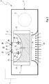
- Fig. 1 shows schematically a household extractor hood 1 with a fan device 2 according to a non-inventive embodiment.
- the household extractor hood 1 can be designed in the form of a hood or chimney and mounted over a hotplate.
- the fan device 2 comprises a spiral housing 3.
- the spiral housing has an axial air inlet 4 and a tangential air outlet 5.
- the air outlet 5 is only indicated by dashed lines, since it lies outside the sectional plane shown.
- the air outlet 5 can be round or angular.
- the fan device also has an electric motor 6.
- the electric motor 6 is flanged to a rear wall 7 of the spiral housing 3 opposite the air inlet 4.
- the fan device 2 comprises a fan wheel 11.
- the fan wheel 11 comprises a central hub 12, blades 13 and a flat connecting element in the form of a bell 14.
- the bell 14 connects the hub 12 to the blades 13 and is air-impermeable.
- the fan wheel 11 is driven by the electric motor 6 and rotates about an axis of rotation designated 15. Insofar as the term “axial” or “radial” is used, this refers to the axis of rotation 15. "Tangential” refers to a circle around the axis of rotation 15.
- the bell 14 and the rear wall 7 axially delimit a space 16 with one another.
- the space 16 is in radial communication with the air outlet 5 by means of an annular gap 17.
- the electric motor 6 rotates the fan wheel 11, which transports air 23 from the air inlet 4 to the air outlet 5.
- exhaust air is removed via a hotplate.
- the air 23 can, for example, be filtered in front of the air inlet 4.
- free-blowing operation it is meant that neither inlet 4 nor outlet 5 are blocked.
- partially throttled operation it is meant that the air inlet 4 or the air outlet 5 or both are partially blocked.
- piping connected to the air outlet 5 forms such a blockage. Such one Piping can be found in kitchens, for example, and is used to transport the air outside the building.
- a negative pressure is created in the space 16, for which the fan device 2, in particular the fan wheel 11, is suitably designed, in particular dimensioned.
- air 24 flows from the surroundings 22 through the openings 21 into the space 16 and thereby flows past the outside 25 of the electric motor 6 and cools it.
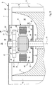
- Fig. 2 shows a fan device 2 according to an embodiment of the invention. The following is only the differences from the embodiment Fig. 1 received.
- Fig. 3 shows a section Fig. 2 in greater detail.
- Fig. 4 shows a view IV Fig. 3 and Fig. 5 a view V from Fig. 4 ,
- the openings 21 in the rear wall 7 each have an air-conducting connection with openings 26 (see Fig. 4 ) in a rear plate 27 of the electric motor 6.
- a swirler 31 can be arranged in the openings 21, 26, which ensures that the inflowing air 24 is swirled.
- the swirled air then hits a stator 33 of the electric motor 6 with electrical windings 34 and cools it.
- the air can also hit a rotor 35 of the electric motor 6, which comprises magnets 36, and also cool it.
- the rotor 35 has the windings 34 and the stator has the magnets 36.
- the air 24 then leaves the electric motor 6 again and flows through the radial openings 37 out of a housing 38, which forms the outer end of the electric motor 6, into the space 16.
- the one in the electric motor 6 by means of the openings 26 and 37 and the housing 38 defined channel is designated 41.
- the rear plate 27 and an air inlet plate 45 hold the rotor 35 rotatably by means of bearings 46.
- the rotor 35 is fixedly connected at one end to the hub 12 of the fan wheel 11.
Landscapes
- Engineering & Computer Science (AREA)
- Mechanical Engineering (AREA)
- General Engineering & Computer Science (AREA)
- Power Engineering (AREA)
- Chemical & Material Sciences (AREA)
- Combustion & Propulsion (AREA)
- Physics & Mathematics (AREA)
- Thermal Sciences (AREA)
- Structures Of Non-Positive Displacement Pumps (AREA)
Description
- Die vorliegende Erfindung betrifft eine Haushalts-Dunstabzugshaube mit einer Lüftervorrichtung sowie ein Verfahren zum Kühlen eines Motors einer Lüftervorrichtung einer Haushalts-Dunstabzugshaube.
- Der Einsatz von Lüftervorrichtungen, beispielsweise Radialluftgebläsen, in Haushaltsgeräten, insbesondere Haushalts-Dunstabzugshauben, ist bekannt. Sie dienen beispielsweise dazu, Luft über Kochstellen abzusaugen. Die Luft wird dabei durch einen Filter gesaugt, um Fett und andere Stoffe aus der Luft herauszufiltern.
- Es wird zwischen ein- und doppelflutigen Lüftervorrichtungen unterschieden. Einflutige Lüftervorrichtungen weisen ein Gehäuse auf, welches lediglich einen axialen Lufteinlass umfasst. Die dem axialen Lufteinlass gegenüberliegende Rückwand des Gehäuses ist geschlossen ausgebildet. Bei doppelflutigen Lüftervorrichtungen ist auch die Rückwand als Lufteinlass ausgebildet, so dass zwei gegenüberliegende, axiale Lufteinlässe gebildet werden.
- Bei einflutigen Lüftervorrichtungen kann der das entsprechende Lüfterrad antreibende Elektromotor lufteinlassseitig oder rückwandseitig angeordnet sein. Die lufteinlassseitige Anordnung des Elektromotors weist den Vorteil auf, dass der Elektromotor mittels der durch den Lufteinlass einströmenden Luft gut gekühlt wird. Nachteilig ist jedoch, dass der lufteinlassseitige Elektromotor mittels eines Gitters oder Streben im Bereich des Lufteinlasses gehalten werden muss, was zu einem erhöhten Strömungswiderstand führt (auch als Versperreffekte bezeichnet).
- Die rückwandseitige Anordnung des Elektromotors weist den Vorteil auf, dass die erwähnten Versperreffekte vermieden werden. Allerdings stellt sich eine ausreichende Kühlung des rückwandseitigen Elektromotors oft schwierig dar, da der Elektromotor typischerweise durch eine Lüfterradglocke von der durch den Lufteinlass einströmenden Luft abgeschirmt ist und diese den Elektromotor entsprechend nicht ausreichend kühlen kann. Die
US 6,216,686 B1 zeigt beispielsweise eine rückwandseitige Anordnung des Elektromotors in einer Dunstabzugshaube. - Die
US 2008/0193275 A1 zeigt einen Elektromotor, der eine Lüftervorrichtung zum Kühlen eines Rotors des Elektromotors umfasst. Die Lüftervorrichtung dreht sich mit dem Rotor zum Ausbilden eines Luftstroms durch den Rotor. - Die
US 4,470,753 A zeigt ein Radialgebläse, insbesondere für Heiz- oder Klimaanlagen von Fahrzeugen, mit einem Gehäuse, dessen Frontseite mit einer Lufteinlassöffnung versehen ist und dessen Rückseite unter Belassen von Öffnungen einen Antriebsmotor für ein Lüfterrad aufnimmt, das einen Lüfterkranz mit Lüfterschaufeln und eine Nabe aufweist, die mittels eines Zwischenstückes ein einteiliges Bauteil bilden, wobei das Zwischenstück mit Durchbrechungen versehen ist, und wobei die Öffnungen in der Gehäuserückseite und/oder dem Antriebsmotor einen für das Ansaugen eines ausreichenden Kühlluftstromes begrenzten Querschnitt aufweisen. - Die
DE 101 62 919 A1 zeigt eine Lüftervorrichtung für eine Dunstabzugshaube, wobei der das entsprechende Lüfterrad antreibende Elektromotor lufteinlassseitig angeordnet ist. - Die
FR 2.209.410 A5 - Die
DE 35 43 822 A1 zeigt einen weiteren Dachventilator. - Vor diesem Hintergrund besteht eine Aufgabe der vorliegenden Erfindung darin, einen verbesserten Ansatz zur Kühlung eines Motors einer Lüftervorrichtung einer Haushalts-Dunstabzugshaube bereitzustellen.
- Zur Lösung dieser Aufgabe wird eine Haushalts-Dunstabzugshaube mit einer Lüftervorrichtung gemäß dem Anspruch 1 vorgeschlagen, welche ein Gehäuse, einen Motor, ein Lüfterrad, einen Raum und Öffnungen aufweist. Das Gehäuse umfasst einen Lufteinlass und einen Luftauslass. Der Motor ist an einer dem Lufteinlass gegenüberliegenden Rückwand des Gehäuses angebracht. Das Lüfterrad ist von dem Motor antreibbar. Der Raum ist axial von dem Lüfterrad und der Rückwand begrenzt. Radial steht der Raum mittels eines Ringspalts mit dem Luftauslass in luftleitender Verbindung. Weiterhin umfasst die Haushalts-Dunstabzugshaube ein Gehäuse, welches den äußeren Abschluss des Motors bildet und radiale Öffnungen zu dem Raum aufweist, und einen rückwandseitigen Lagerschild, der Öffnungen aufweist. Zumindest in einem freiblasenden oder teilgedrosselten Betrieb der Lüftervorrichtung ist ein Unterdruck in dem Raum erzeugbar. Die Öffnungen sind zur Umgebung hin in der Rückwand ausgebildet. Die Öffnungen stehen jeweils in luftleitender Verbindung mit den Öffnungen des Lagerschilds, wobei ein Kanal mittels der Öffnungen des Lagerschilds, des Gehäuses und der radialen Öffnungen desselben definiert ist. Von der Öffnung in den Raum strömende Luft kühlt den Motor. Luft strömt durch die radialen Öffnungen des Gehäuses aus dem weiteren Gehäuse und heraus in den Raum. Es ist ein Mittel in Form eines Schaufelrads auf einem Rotor des Motors innerhalb des weiteren Gehäuses vorgesehen, welches dazu eingerichtet ist, zumindest in einem vollständig gedrosselten Betrieb der Lüftervorrichtung ein Rückströmen von Luft aus dem Raum zur Öffnung hin zu verhindern.
- Es wurde erkannt, dass sich ein Unterdruck in dem Raum zwischen dem Lüfterrad und der Rückwand dazu nutzen lässt, einen Luftstrom durch die Öffnung in der Rückwand zu erzeugen, welcher den Motor kühlt. Trotz der rückwandseitigen Anordnung des Motors und Abschottung desselben von dem Lufteinlass durch das Lüfterrad lässt sich der Motor somit ausreichend kühlen.
- "Axial" und "radial" bezieht sich vorliegend immer auf die Lüfterraddrehachse, soweit nichts Gegenteiliges angegeben ist. "Freiblasend" meint, dass weder der Lufteinlass noch der Luftauslass der Lüftervorrichtung versperrt ist. "Teilgedrosselt" meint, dass der Lufteinlass und/oder Luftauslass der Lüftervorrichtung teilweise versperrt ist. Eine solche teilweise Drosselung ergibt sich bei Haushalts-Dunstabzugshauben dadurch, dass die Lüftervorrichtung mit einer Verrohrung zum Abführen der gefilterten Luft verbunden wird, wie es typischerweise in Küchen der Fall ist. Bei dem Motor handelt es sich typischerweise um einen Elektromotor. Das Gehäuse ist typischerweise als Spiralgehäuse ausgeführt.
- Der Lufteinlass kann axial und der Luftauslass kann tangential ausgeführt sein. "Tangential" meint eine Richtung entlang einer Tangente zu einem Kreis um die Lüfterdrehachse.
- Nicht-erfindungsgemäß sind die Öffnungen derart vorgesehen, dass die Luft entlang einer Außenseite des Motors strömt. Je nachdem, ob es sich um einen Motor mit Innenläufer oder Außenläufer handelt, kann die Außenseite des Motors ortsfest oder bewegt sein. Beispielsweise kann die Außenseite in Form eines Gehäuses ausgebildet sein.
- Erfindungsgemäß weist der Motor einen Kanal für ein Hindurchströmen der Luft und dadurch Kühlen des Motors auf, welcher einerseits mit der Öffnung und andererseits mit dem Raum in luftleitender Verbindung steht. Eine solche "Kühlung von innen" kann zusätzlich zu der vorstehend beschriebenen Kühlung des Motors von außen vorgesehen sein.
- Gemäß einer weiteren Ausführungsform führt der Kanal durch einen Stator und/oder Rotor des Motors und/oder entlang dieser. Bei einer solchen Kühlung des Rotors ist mit einer nur geringen Geräuschentwicklung zu rechnen, da die Umfangsgeschwindigkeiten gering sind.
- Bevorzugt führt der Kanal an elektrischen Wicklungen des Motors vorbei. Somit kann eine Kühlung gezielt dort erfolgen, wo die Wärme entsteht.
- Gemäß einer weiteren Ausführungsform ist ein Mittel zum Verwirbeln, insbesondere zum turbulenten und/oder spiralförmigen Verwirbeln, der durch den Stator und/oder Rotor strömenden oder an diesen vorbeiströmenden Luft vorgesehen. Das Führen von verwirbelter Luft durch den Stator oder Rotor oder durch beide verbessert eine Kühlung derselben noch weiter. Ferner kann die verwirbelte Luft entlang des Stators oder Rotors oder entlang beider zur besseren Kühlung geführt werden.
- Das Lüfterrad kann eine Nabe und Schaufeln aufweisen, welche mittels eines flächigen Verbindungselements miteinander verbunden sind. Das Lüfterrad kann von dem Motor mittels der Nabe antreibbar vorgesehen sein. Das flächige Verbindungselement kann zusammen mit der Rückwand den Raum axial begrenzen.
- Gemäß einer Ausführungsform ist das flächige Verbindungselement geschlossen und/oder glockenförmig ausgebildet. "Geschlossen" meint, dass keinerlei insbesondere axiale Durchbrüche in dem flächigen Verbindungselement vorgesehen sind, die ein Strömen von Luft aus dem Druckraum in dem Lüfterrad in den zwischen dem Verbindungselement und der Rückwand gebildeten Raum zulassen würden. Turbulenzen bzw. eine entsprechende Geräuschentwicklung kann somit vermieden werden.
- Es ist ein Mittel vorgesehen, welches dazu eingerichtet ist, zumindest in einem vollständig gedrosselten Betrieb der Lüftervorrichtung ein Rückströmen von Luft aus dem Raum zur Öffnung hin zu verhindern. Mit "vollständig gedrosseltem Betrieb" ist gemeint, dass der Einlass und/oder Auslass des Lüfters vollständig verschlossen ist. Im vollständig gedrosselten Betrieb der Lüftervorrichtung kann es, je nach Bauart, vorkommen, dass in dem Raum anstelle eines Unterdrucks ein Überdruck entsteht. In diesem Fall würde Luft aus dem Raum in die Umgebung zurückgedrückt werden. Dies ist aber für bestimmte Anwendungen nicht wünschenswert. Das Mittel ist in Form mehrerer kleiner Schaufeln ausgebildet, welche auf dem Rotor des Motors angrenzend an die Öffnung oder angrenzend an einen mit der Öffnung in Verbindung stehenden Kanal positioniert sind. Der von dem Mittel erzeugte Gegendruck ist dabei im Verhältnis zu dem im freiblasenden oder teilgedrosselten Betrieb der Lüftervorrichtung erzeugten Unterdruck in dem Raum derart klein, dass die Luft im freiblasenden oder teilgedrosselten Betrieb unbeschadet des Mittels von der Öffnung in den Raum strömen kann.
- Der Erfindung umfasst ebenfalls ein Verfahren gemäß dem Anspruch 6, dieses Verfahren stellt ein Verfahren zum Kühlen eines Motors einer Lüftervorrichtung einer Haushalts-Dunstabzugshaube, wie vorstehend beschrieben, bereit. In einem freiblasenden oder teilgedrosselten Betrieb der Lüftervorrichtung wird ein Unterdruck in dem Raum erzeugt, wodurch Luft durch die Öffnung in den Raum strömt und dabei den Motor kühlt, wobei zumindest in einem vollständig gedrosselten Betrieb der Lüftervorrichtung mit Hilfe des Schaufelrads ein Rückströmen von Luft aus dem Raum zur Öffnung hin verhindert wird.
- Nicht-erfindungsgemäß wird die Luft außenseitig an dem Motor vorbeigeführt.
- Erfindungsgemäß wird die Luft durch den Motor hindurchgeführt. Gemäß einer weiteren Ausführungsform wird die Luft durch einen Stator und/oder Rotor des Motors oder an diesen vorbei geführt. Bevorzugt wird die Luft an elektrischen Wicklungen des Motors vorbeigeführt.
- Gemäß einer Ausführungsform wird die durch den Stator oder Rotor strömende oder an diesen vorbeiströmende Luft verwirbelt, insbesondere turbulent und spiralförmig verwirbelt.
- Weitere mögliche Implementierungen der Erfindung umfassen auch nicht explizit genannte Kombinationen von zuvor oder im Folgenden bezüglich der Ausführungsbeispiele beschriebenen Merkmale oder Ausführungsformen der Lüftervorrichtung, der Haushalts-Dunstabzugshaube oder des Verfahrens. Der Fachmann wird dabei auch Einzelaspekte als Verbesserungen oder Ergänzungen zu der jeweiligen Grundform der Erfindung hinzufügen oder abändern.
- Der Umfang der Erfindung ist ausschließlich durch die beigefügten Ansprüche 1 und 6 definiert. Weitere vorteilhafte Ausgestaltungen und Aspekte der Erfindung sind Gegenstand der Unteransprüche. Im Weiteren wird die Erfindung anhand von Ausführungsformen unter Bezugnahme auf die beigelegten Figuren näher erläutert.
- Es zeigt dabei:
-
Fig. 1 : schematisch einen Schnitt durch eine Haushalts-Dunstabzugshaube mit einer Lüftervorrichtung gemäß einer nicht-erfindungsgemäßen Ausführungsform; -
Fig. 2 : eine Lüftervorrichtung gemäß einer erfindungsgemäßen Ausführungsform; -
Fig. 3 : einen Teilbereich ausFig. 2 in größerem Detail; -
Fig. 4 : eine vergrößerte Ansicht IV ausFig. 3 ; und -
Fig. 5 : eine Ansicht V ausFig. 4 . - In den Figuren bezeichnen gleiche Bezugszeichen gleiche oder funktionsgleiche Komponenten, soweit nichts Gegenteiliges angegeben ist.
-
Fig. 1 zeigt schematisch eine Haushalts-Dunstabzugshaube 1 mit einer Lüftervorrichtung 2 gemäß einer nicht-erfindungsgemäßen Ausführungsform. Die Haushalts-Dunstabzugshaube 1 kann in Form einer Haube oder Esse ausgebildet und über einer Kochstelle montiert sein. - Die Lüftervorrichtung 2 umfasst ein Spiralgehäuse 3. Das Spiralgehäuse weist einen axialen Lufteinlass 4 sowie einen tangentialen Luftauslass 5 auf. Der Luftauslass 5 ist lediglich gestrichelt angedeutet, da dieser außerhalb der dargestellten Schnittebene liegt. Der Luftauslass 5 kann rund oder eckig ausgeführt sein.
- Die Lüftervorrichtung weist weiterhin einen Elektromotor 6 auf. Der Elektromotor 6 ist an einer dem Lufteinlass 4 gegenüberliegenden Rückwand 7 des Spiralgehäuses 3 angeflanscht.
- Ferner umfasst die Lüftervorrichtung 2 ein Lüfterrad 11. Das Lüfterrad 11 umfasst eine mittige Nabe 12, Schaufeln 13 sowie ein flächiges Verbindungselement in Form einer Glocke 14. Die Glocke 14 verbindet die Nabe 12 mit den Schaufeln 13 und ist luftundurchlässig ausgebildet. Das Lüfterrad 11 wird von dem Elektromotor 6 angetrieben und rotiert dabei um eine mit 15 bezeichnete Drehachse. Soweit vorliegend von "axial" oder "radial" die Rede ist, so bezieht sich dies auf die Drehachse 15. "Tangential" bezieht sich auf einen Kreis um die Drehachse 15.
- Die Glocke 14 und die Rückwand 7 begrenzen miteinander axial einen Raum 16. Der Raum 16 steht radial mittels eines Ringspalts 17 mit dem Luftauslass 5 in luftleitender Verbindung.
- In der Rückwand 7 sind zwei Öffnungen 21 zur Umgebung 22 hin ausgebildet.
- In einem freiblasenden oder teilgedrosselten Betrieb der Lüftervorrichtung 2 dreht der Elektromotor 6 das Lüfterrad 11, welches Luft 23 von dem Lufteinlass 4 zu dem Luftauslass 5 transportiert. Dadurch wird beispielsweise Abluft über einer Kochstelle abtransportiert. Die Luft 23 kann beispielsweise vor dem Lufteinlass 4 gefiltert werden. Mit "freiblasendem Betrieb" ist gemeint, dass weder der Einlass 4 noch der Auslass 5 versperrt sind. Mit "teilgedrosseltem Betrieb" ist gemeint, dass der Lufteinlass 4 oder der Luftauslass 5 oder auch beide teilweise versperrt sind. So bildet beispielsweise eine sich an den Luftauslass 5 anschließende Verrohrung eine solche Versperrung. Eine derartige Verrohrung ist beispielsweise in Küchen anzutreffen und dient dazu, die Luft nach außerhalb des Gebäudes zu transportieren.
- In dem freiblasenden oder teilgedrosselten Betrieb entsteht ein Unterdruck in dem Raum 16, wozu die Lüftervorrichtung 2, insbesondere das Lüfterrad 11, geeignet ausgebildet, insbesondere dimensioniert, ist. Dadurch strömt Luft 24 aus der Umgebung 22 durch die Öffnungen 21 in den Raum 16 ein und strömt dabei an der Außenseite 25 des Elektromotors 6 vorbei und kühlt diesen.
-
Fig. 2 zeigt eine Lüftervorrichtung 2 gemäß einer erfindungsgemäßen Ausführungsform. Nachfolgend wird lediglich auf die Unterschiede gegenüber der Ausführungsform nachFig. 1 eingegangen.Fig. 3 zeigt einen Ausschnitt ausFig. 2 in größerem Detail.Fig. 4 zeigt eine Ansicht IV ausFig. 3 undFig. 5 eine Ansicht V ausFig. 4 . - Bei der Lüftervorrichtung 2 gemäß den
Fig. 2-5 stehen die Öffnungen 21 in der Rückwand 7 jeweils in luftleitender Verbindung mit Öffnungen 26 (sieheFig. 4 ) in einem rückwandseitigen Lagerschild 27 des Elektromotors 6. In den Öffnungen 21, 26 kann ein Verwirbler 31 angeordnet sein, welcher dafür sorgt, dass die einströmende Luft 24 verwirbelt wird. Die verwirbelte Luft trifft dann auf einen Stator 33 des Elektromotors 6 mit elektrischen Wicklungen 34 und kühlt diesen. Gemäß einer Ausführungsform kann die Luft auch auf einen Rotor 35 des Elektromotors 6 treffen, welcher Magnete 36 umfasst, und auch diesen kühlen. Gemäß einer weiteren Ausführungsform weist der Rotor 35 die Wicklungen 34 und der Stator die Magnete 36 auf. - Anschließend verlässt die Luft 24 wieder den Elektromotor 6 und strömt durch die radialen Öffnungen 37 aus einem Gehäuse 38, welches den äußeren Abschluss des Elektromotors 6 bildet, heraus in den Raum 16. Der in dem Elektromotor 6 mittels der Öffnungen 26 und 37 sowie dem Gehäuse 38 definierte Kanal ist mit 41 bezeichnet.
- Im vollständig gedrosselten Betrieb der Lüftervorrichtung 2, also wenn entweder der Lufteinlass 4 oder der Luftauslass 5 oder beide vollständig verschlossen sind, kann es dazu kommen, dass in dem Raum 16 ein Überdruck herrscht. Ohne entsprechende Gegenmaßnahmen würde dann Luft 42 (siehe
Fig. 3 ) aus dem Raum 16 durch die Öffnungen 37, 26 und 21 zurück in die Umgebung 43 strömen. Um dies zu unterbinden, ist ein Mittel in Form eines kleinen Schaufelrads 44 auf dem Rotor 35 angebracht, welches den entsprechenden Gegendruck erzeugt. Dieser Gegendruck ist jedoch gegenüber dem Unterdruck, welcher in dem Raum 16 im freiblasenden oder teilgedrosselten Betrieb der Lüftervorrichtung 2 herrscht, klein, so dass bei den beiden letztgenannten Betriebsarten die Luft 24 nach wie vor problemlos von den Öffnungen 21 in den Raum 16 strömen und dabei den Elektromotor 6 effektiv kühlen kann. - Der Vollständigkeit halber sei erwähnt, dass das rückwandseitige Lagerschild 27 sowie ein lufteinlassseitiges Lagerschild 45 mittels Lager 46 den Rotor 35 drehbar gelagert halten. Der Rotor 35 ist an seinem einen Ende fest mit der Nabe 12 des Lüfterrads 11 verbunden.
- Obwohl die Erfindung anhand von Ausführungsbeispielen beschrieben wurde, ist sie vielfältig modifizierbar. Der Umfang der Erfindung ist ausschließlich durch die beigefügten Ansprüche definiert.
-
- 1
- Dunstabzugshaube
- 2
- Lüftervorrichtung
- 3
- Spiralgehäuse
- 4
- Lufteinlass
- 5
- Luftauslass
- 6
- Elektromotor
- 7
- Rückwand
- 11
- Lüfterrad
- 12
- Nabe
- 13
- Schaufel
- 14
- Glocke
- 15
- Drehachse
- 16
- Raum
- 17
- Ringspalt
- 21
- Öffnung
- 22
- Umgebung
- 23
- Luft
- 24
- Luft
- 25
- Außenseite
- 26
- Öffnung
- 27
- Lagerschild
- 31
- Verwirbler
- 33
- Stator
- 34
- elektrische Wicklungen
- 35
- Rotor
- 36
- Magnet
- 37
- Öffnung
- 41
- Kanal
- 42
- Luft
- 43
- Umgebung
- 44
- Schaufelrad
- 45
- Lagerschild
- 46
- Lager
Claims (9)
- Haushalts-Dunstabzugshaube (1) mit einer Lüftervorrichtung (2), mit einem Gehäuse (3), welches einen Lufteinlass (4) und einen Luftauslass (5) aufweist, einem an einer dem Lufteinlass (4) gegenüberliegenden Rückwand (7) des Gehäuses (3) angebrachten Motor (6), einem Lüfterrad (11), welches von dem Motor (6) antreibbar ist, einem Raum (16), welcher axial von dem Lüfterrad (11) und der Rückwand (7) begrenzt ist und radial mittels eines Ringspalts (17) mit dem Luftauslass (5) in luftleitender Verbindung steht, einem weiteren Gehäuse (38), welches den äußeren Abschluss des Motors (6) bildet und radiale Öffnungen (37) zu dem Raum (16) aufweist, einem rückwandseitigen Lagerschild (27), der Öffnungen (26) aufweist, wobei zumindest in einem freiblasenden oder teilgedrosselten Betrieb der Lüftervorrichtung (2) ein Unterdruck in dem Raum (16) erzeugbar ist, und Öffnungen (21) zur Umgebung (22) in der Rückwand (7), wobei die Öffnungen (21) der Rückwand (7) jeweils in luftleitender Verbindung mit den Öffnungen (26) des Lagerschilds (27) stehen, wobei ein Kanal (41) mittels der Öffnungen (26) des Lagerschilds (27), des weiteren Gehäuses (38) und der radialen Öffnungen (37) desselben definiert ist, wobei im Betrieb der Lüftervorrichtung von den Öffnungen (21) der Rückwand (7) in den Raum (16) strömende Luft (24) den Motor (6) kühlt und die Luft (24) durch die radialen Öffnungen (37) des weiteren Gehäuses (38) aus dem weiteren Gehäuse (38) und heraus in den Raum (16) strömt, und wobei ein Mittel in Form eines Schaufelrads (44) auf einem Rotor (35) des Motors (6) innerhalb des weiteren Gehäuses (38) vorgesehen ist, welches dazu eingerichtet ist, zumindest in einem vollständig gedrosselten Betrieb der Lüftervorrichtung (2) ein Rückströmen von Luft (42) aus dem Raum (16) zu den Öffnungen (21) der Rückwand (7) hin zu verhindern.
- Haushalts-Dunstabzugshaube nach Anspruch 1, dadurch gekennzeichnet, dass der Kanal (41) durch einen Stator (33) und/oder den Rotor (35) des Motors (6) und/oder entlang dieser führt.
- Haushalts-Dunstabzugshaube nach Anspruch 2, dadurch gekennzeichnet, dass der Kanal (41) an elektrischen Wicklungen (34) des Motors (6) vorbeiführt.
- Haushalts-Dunstabzugshaube nach Anspruch 2 oder 3, dadurch gekennzeichnet, dass ein Mittel (31) zum Verwirbeln, insbesondere turbulenten und/oder spiralförmigen Verwirbeln, der durch den Stator (33) und/oder Rotor (35) strömenden oder an diesen vorbeiströmenden Luft (24) vorgesehen ist.
- Haushalts-Dunstabzugshaube nach einem der Ansprüche 1 - 4, dadurch gekennzeichnet, dass das Lüfterrad (11) ein flächiges Verbindungselement (14), insbesondere in Form eine Glocke, aufweist, welches den Raum (16) axial begrenzt.
- Verfahren zum Kühlen eines Motors (6) einer Haushalts-Dunstabzugshaube (1) nach einem der Ansprüche 1 - 5, wobei zumindest in einem freiblasenden oder teilgedrosselten Betrieb der Lüftervorrichtung (2) ein Unterdruck in dem Raum (16) erzeugt wird, wodurch Luft (24) durch die Öffnungen (21) der Rückwand (7) in den Raum (16) strömt und dabei den Motor (6) kühlt,
wobei die Luft (24) durch die radialen Öffnungen (37) des weiteren Gehäuses (38) aus dem weiteren Gehäuse (38) und heraus in den Raum (16) strömt, wobei
zumindest in einem vollständig gedrosselten Betrieb der Lüftervorrichtung (2) mit Hilfe des Schaufelrads (44) ein Rückströmen von Luft (42) aus dem Raum (16) zu den Öffnungen (21) der Rückwand (7) hin verhindert wird. - Verfahren nach Anspruch 6, dadurch gekennzeichnet, dass die Luft (24) durch den Motor (6) hindurchgeführt wird.
- Verfahren nach Anspruch 7, dadurch gekennzeichnet, dass die Luft (24) durch einen Stator (33) und/oder den Rotor (35) des Motors (6) und/oder entlang dieser geführt wird.
- Verfahren nach Anspruch 8, wobei die durch den Stator (33) oder Rotor (35) strömende oder an diesen vorbeiströmende Luft (24), insbesondere turbulent oder spiralförmig, verwirbelt wird.
Applications Claiming Priority (1)
| Application Number | Priority Date | Filing Date | Title |
|---|---|---|---|
| DE102011088074A DE102011088074A1 (de) | 2011-12-09 | 2011-12-09 | Lüftervorrichtung, Haushaltsgerät sowie Verfahren zum Kühlen eines Motors einer Lüftervorrichtung |
Publications (3)
| Publication Number | Publication Date |
|---|---|
| EP2602489A2 EP2602489A2 (de) | 2013-06-12 |
| EP2602489A3 EP2602489A3 (de) | 2015-12-23 |
| EP2602489B1 true EP2602489B1 (de) | 2020-01-08 |
Family
ID=47294713
Family Applications (1)
| Application Number | Title | Priority Date | Filing Date |
|---|---|---|---|
| EP12195045.5A Active EP2602489B1 (de) | 2011-12-09 | 2012-11-30 | Haushalts-Dunstabzugshaube sowie Verfahren zum Kühlen eines Motors einer Lüftervorrichtung der Haushalts-Dunstabzugshaube |
Country Status (2)
| Country | Link |
|---|---|
| EP (1) | EP2602489B1 (de) |
| DE (1) | DE102011088074A1 (de) |
Families Citing this family (11)
| Publication number | Priority date | Publication date | Assignee | Title |
|---|---|---|---|---|
| CN105444232A (zh) * | 2015-12-29 | 2016-03-30 | 安徽国茂机电设备有限公司 | 一种油烟净化一体机 |
| CN106524263B (zh) * | 2016-12-16 | 2018-11-23 | 宁波方太厨具有限公司 | 一种吸油烟机 |
| CN110822506B (zh) * | 2018-08-10 | 2021-04-20 | 佛山市顺德区美的洗涤电器制造有限公司 | 用于吸油烟机的蜗壳、风机和吸油烟机 |
| DE102018129608B4 (de) | 2018-11-23 | 2022-06-15 | Ebm-Papst St. Georgen Gmbh & Co. Kg | Rotormontageeinheit |
| CN110186082B (zh) * | 2019-05-07 | 2024-01-23 | 宁波方太厨具有限公司 | 一种侧吸式吸油烟机 |
| CN110375349B (zh) * | 2019-06-27 | 2021-05-18 | 宁波方太厨具有限公司 | 一种侧吸式吸油烟机 |
| CN110375360A (zh) * | 2019-06-27 | 2019-10-25 | 宁波方太厨具有限公司 | 一种侧吸式吸油烟机 |
| CN110594805B (zh) * | 2019-08-09 | 2021-04-16 | 宁波方太厨具有限公司 | 一种侧吸式吸油烟机 |
| CN111503055B (zh) * | 2020-05-06 | 2025-05-30 | 珠海格力电器股份有限公司 | 风机组件、降温装置、具有风机组件的装置及控制方法 |
| CN117267766B (zh) * | 2022-06-15 | 2026-07-10 | 宁波方太厨具有限公司 | 一种吸油烟机及其控制方法 |
| CN116398916B (zh) * | 2023-04-27 | 2025-09-30 | 宁波方太厨具有限公司 | 吸油烟机及吸油烟机的尺寸控制方法 |
Citations (4)
| Publication number | Priority date | Publication date | Assignee | Title |
|---|---|---|---|---|
| FR2209410A5 (de) * | 1972-11-03 | 1974-06-28 | Technicair Sa | |
| DE3543833A1 (de) * | 1984-12-12 | 1987-12-03 | Leithner Joachim | Dachventilator |
| US6216686B1 (en) * | 2000-06-23 | 2001-04-17 | Robert Chiu | Slanted motor housing for range hood |
| US20080193275A1 (en) * | 2005-05-10 | 2008-08-14 | Pietro De Filippis | Electric Machine |
Family Cites Families (12)
| Publication number | Priority date | Publication date | Assignee | Title |
|---|---|---|---|---|
| DE7521820U (de) * | 1975-07-09 | 1976-12-30 | Bosch-Siemens Hausgeraete Gmbh, 7000 Stuttgart | Geblaese fuer die luftbewegung in raeumen mit fettabscheidung |
| SE443408B (sv) * | 1979-09-28 | 1986-02-24 | Sueddeutsche Kuehler Behr | Radialflekt for verme- eller luftkonditioneringsanleggningar i fordon |
| GB2132335A (en) * | 1982-12-21 | 1984-07-04 | Chung Tsung Cheng | Apparatus for exhausting gaseous emissions during cooking |
| JPS63309796A (ja) * | 1987-06-11 | 1988-12-16 | Mitsubishi Electric Corp | 排気再循環用送風機 |
| DE19547674A1 (de) * | 1995-12-20 | 1997-06-26 | Temic Auto Electr Motors Gmbh | Radialgebläse, insbesondere für Heizungs- und Klimaanlagen von Kraftfahrzeugen |
| FR2766882B1 (fr) * | 1997-07-31 | 2002-01-11 | Valeo Climatisation | Ventilateur centrifuge a conduit perfectionne de refroidissement du moteur, notamment pour vehicule automobile |
| DE10162919A1 (de) * | 2001-12-20 | 2003-07-03 | Bsh Bosch Siemens Hausgeraete | Lüftervorrichtung |
| FR2859579B1 (fr) * | 2003-09-10 | 2006-03-03 | Valeo Climatisation | Dispositif pour le support d'un moteur electrique entrainant une turbine, en particulier pour un appareil de chauffage, ventilation et/ou climatisation de vehicule automobile |
| JP4981535B2 (ja) * | 2007-06-20 | 2012-07-25 | 株式会社ケーヒン | 遠心式送風機 |
| DE102008048433A1 (de) * | 2008-09-23 | 2010-03-25 | Daimler Ag | Radialgebläse |
| DE102010005944A1 (de) * | 2010-01-27 | 2011-09-08 | Behr Gmbh & Co. Kg | Klimaanlage |
| DE102010012392A1 (de) * | 2010-03-22 | 2011-09-22 | Ebm-Papst Mulfingen Gmbh & Co. Kg | Ventilator |
-
2011
- 2011-12-09 DE DE102011088074A patent/DE102011088074A1/de not_active Withdrawn
-
2012
- 2012-11-30 EP EP12195045.5A patent/EP2602489B1/de active Active
Patent Citations (4)
| Publication number | Priority date | Publication date | Assignee | Title |
|---|---|---|---|---|
| FR2209410A5 (de) * | 1972-11-03 | 1974-06-28 | Technicair Sa | |
| DE3543833A1 (de) * | 1984-12-12 | 1987-12-03 | Leithner Joachim | Dachventilator |
| US6216686B1 (en) * | 2000-06-23 | 2001-04-17 | Robert Chiu | Slanted motor housing for range hood |
| US20080193275A1 (en) * | 2005-05-10 | 2008-08-14 | Pietro De Filippis | Electric Machine |
Also Published As
| Publication number | Publication date |
|---|---|
| EP2602489A2 (de) | 2013-06-12 |
| DE102011088074A1 (de) | 2013-06-13 |
| EP2602489A3 (de) | 2015-12-23 |
Similar Documents
| Publication | Publication Date | Title |
|---|---|---|
| EP2602489A2 (de) | Lüftervorrichtung, Haushaltsgerät sowie Verfahren zum Kühlen eines Motors einer Lüftervorrichtung | |
| DE19909507C1 (de) | Radialgebläse, insbesondere für Heizungs- und Klimaanlagen | |
| EP2549116B1 (de) | Axiallüfter mit zusätzlichem Strömungskanal | |
| EP2211444B1 (de) | Elektromotor mit Kühlventilatorwirkung | |
| DE102011017419A1 (de) | Ablenkeinheit für eine Gasströmung in einem Kompressor und Kompressor, der diese enthält | |
| WO2017041997A1 (de) | Turbo-lüfter mit kühlkörper | |
| DE102011015784A1 (de) | Ventilator | |
| DE102005026421B4 (de) | Wärme ableitende Vorrichtung | |
| DE102010046870A1 (de) | Seitenkanalgebläse, insbesondere Sekundärluftgebläse für eine Verbrennungskraftmaschine | |
| DE202011004708U1 (de) | Ventilator | |
| DE102008000168A1 (de) | Gebläseanordnung mit Vordrallerzeuger | |
| DE112014001084T5 (de) | Variable Düseneinheit und Lader mit variabler Kapazität | |
| DE102008046508A1 (de) | Lüftervorrichtung zur Belüftung eines Verbrennungsmotors, Kühlsystem mit zumindest einer Lüftervorrichtung | |
| DE112013005167T5 (de) | Verdichterrad eines Radialverdichters eines Abgasturboladers | |
| EP1706645B1 (de) | Mehrstufige reibungsvakuumpumpe | |
| DE102010039219A1 (de) | Lüfter, insbesondere für ein Motorkühlungsgebläse in einem Kraftfahrzeug | |
| EP3880966A1 (de) | Diagonalventilator mit drallreduzierung am diagonallaufrad | |
| DE102010012910A1 (de) | Gebläsemotorkühlung | |
| DE102015204466A1 (de) | Anordnung mit zwei Verdichtern, Verfahren zum Nachrüsten | |
| DE102004022962B4 (de) | Zentrifugallüfter und Gehäuse davon | |
| WO2014139780A1 (de) | Gehäuse für ein radialgebläse einer dunstabzugshaube | |
| DE202007005784U1 (de) | Lüftungseinheit zur Fremdbelüftung eines Elektromotors | |
| EP3421806B1 (de) | Gebläse | |
| WO2014023577A1 (de) | Gebläse mit lufteintrittsdüse für verwirbelten luftstrom sowie lufteintrittsdüse für ein gebläse | |
| DE102014226341A1 (de) | Verdichter, Abgasturbolader und Brennkraftmaschine |
Legal Events
| Date | Code | Title | Description |
|---|---|---|---|
| PUAI | Public reference made under article 153(3) epc to a published international application that has entered the european phase |
Free format text: ORIGINAL CODE: 0009012 |
|
| AK | Designated contracting states |
Kind code of ref document: A2 Designated state(s): AL AT BE BG CH CY CZ DE DK EE ES FI FR GB GR HR HU IE IS IT LI LT LU LV MC MK MT NL NO PL PT RO RS SE SI SK SM TR |
|
| AX | Request for extension of the european patent |
Extension state: BA ME |
|
| RAP1 | Party data changed (applicant data changed or rights of an application transferred) |
Owner name: BSH HAUSGERAETE GMBH |
|
| PUAL | Search report despatched |
Free format text: ORIGINAL CODE: 0009013 |
|
| AK | Designated contracting states |
Kind code of ref document: A3 Designated state(s): AL AT BE BG CH CY CZ DE DK EE ES FI FR GB GR HR HU IE IS IT LI LT LU LV MC MK MT NL NO PL PT RO RS SE SI SK SM TR |
|
| AX | Request for extension of the european patent |
Extension state: BA ME |
|
| RIC1 | Information provided on ipc code assigned before grant |
Ipc: H02K 9/06 20060101ALI20151119BHEP Ipc: F04D 25/08 20060101AFI20151119BHEP Ipc: F04D 29/58 20060101ALI20151119BHEP Ipc: F04D 17/16 20060101ALI20151119BHEP Ipc: F24C 15/20 20060101ALI20151119BHEP |
|
| 17P | Request for examination filed |
Effective date: 20160623 |
|
| RBV | Designated contracting states (corrected) |
Designated state(s): AL AT BE BG CH CY CZ DE DK EE ES FI FR GB GR HR HU IE IS IT LI LT LU LV MC MK MT NL NO PL PT RO RS SE SI SK SM TR |
|
| STAA | Information on the status of an ep patent application or granted ep patent |
Free format text: STATUS: EXAMINATION IS IN PROGRESS |
|
| 17Q | First examination report despatched |
Effective date: 20170119 |
|
| GRAP | Despatch of communication of intention to grant a patent |
Free format text: ORIGINAL CODE: EPIDOSNIGR1 |
|
| STAA | Information on the status of an ep patent application or granted ep patent |
Free format text: STATUS: GRANT OF PATENT IS INTENDED |
|
| RIC1 | Information provided on ipc code assigned before grant |
Ipc: F04D 25/08 20060101AFI20190719BHEP Ipc: F24C 15/20 20060101ALI20190719BHEP Ipc: H02K 5/20 20060101ALI20190719BHEP Ipc: H02K 9/06 20060101ALI20190719BHEP Ipc: F04D 17/16 20060101ALI20190719BHEP Ipc: F04D 29/58 20060101ALI20190719BHEP |
|
| INTG | Intention to grant announced |
Effective date: 20190807 |
|
| GRAS | Grant fee paid |
Free format text: ORIGINAL CODE: EPIDOSNIGR3 |
|
| GRAA | (expected) grant |
Free format text: ORIGINAL CODE: 0009210 |
|
| STAA | Information on the status of an ep patent application or granted ep patent |
Free format text: STATUS: THE PATENT HAS BEEN GRANTED |
|
| AK | Designated contracting states |
Kind code of ref document: B1 Designated state(s): AL AT BE BG CH CY CZ DE DK EE ES FI FR GB GR HR HU IE IS IT LI LT LU LV MC MK MT NL NO PL PT RO RS SE SI SK SM TR |
|
| REG | Reference to a national code |
Ref country code: GB Ref legal event code: FG4D Free format text: NOT ENGLISH |
|
| REG | Reference to a national code |
Ref country code: CH Ref legal event code: EP |
|
| REG | Reference to a national code |
Ref country code: DE Ref legal event code: R096 Ref document number: 502012015682 Country of ref document: DE |
|
| REG | Reference to a national code |
Ref country code: IE Ref legal event code: FG4D Free format text: LANGUAGE OF EP DOCUMENT: GERMAN |
|
| REG | Reference to a national code |
Ref country code: AT Ref legal event code: REF Ref document number: 1223067 Country of ref document: AT Kind code of ref document: T Effective date: 20200215 |
|
| REG | Reference to a national code |
Ref country code: NL Ref legal event code: MP Effective date: 20200108 |
|
| REG | Reference to a national code |
Ref country code: LT Ref legal event code: MG4D |
|
| PG25 | Lapsed in a contracting state [announced via postgrant information from national office to epo] |
Ref country code: RS Free format text: LAPSE BECAUSE OF FAILURE TO SUBMIT A TRANSLATION OF THE DESCRIPTION OR TO PAY THE FEE WITHIN THE PRESCRIBED TIME-LIMIT Effective date: 20200108 Ref country code: LT Free format text: LAPSE BECAUSE OF FAILURE TO SUBMIT A TRANSLATION OF THE DESCRIPTION OR TO PAY THE FEE WITHIN THE PRESCRIBED TIME-LIMIT Effective date: 20200108 Ref country code: NL Free format text: LAPSE BECAUSE OF FAILURE TO SUBMIT A TRANSLATION OF THE DESCRIPTION OR TO PAY THE FEE WITHIN THE PRESCRIBED TIME-LIMIT Effective date: 20200108 Ref country code: NO Free format text: LAPSE BECAUSE OF FAILURE TO SUBMIT A TRANSLATION OF THE DESCRIPTION OR TO PAY THE FEE WITHIN THE PRESCRIBED TIME-LIMIT Effective date: 20200408 Ref country code: FI Free format text: LAPSE BECAUSE OF FAILURE TO SUBMIT A TRANSLATION OF THE DESCRIPTION OR TO PAY THE FEE WITHIN THE PRESCRIBED TIME-LIMIT Effective date: 20200108 Ref country code: PT Free format text: LAPSE BECAUSE OF FAILURE TO SUBMIT A TRANSLATION OF THE DESCRIPTION OR TO PAY THE FEE WITHIN THE PRESCRIBED TIME-LIMIT Effective date: 20200531 |
|
| PG25 | Lapsed in a contracting state [announced via postgrant information from national office to epo] |
Ref country code: LV Free format text: LAPSE BECAUSE OF FAILURE TO SUBMIT A TRANSLATION OF THE DESCRIPTION OR TO PAY THE FEE WITHIN THE PRESCRIBED TIME-LIMIT Effective date: 20200108 Ref country code: SE Free format text: LAPSE BECAUSE OF FAILURE TO SUBMIT A TRANSLATION OF THE DESCRIPTION OR TO PAY THE FEE WITHIN THE PRESCRIBED TIME-LIMIT Effective date: 20200108 Ref country code: GR Free format text: LAPSE BECAUSE OF FAILURE TO SUBMIT A TRANSLATION OF THE DESCRIPTION OR TO PAY THE FEE WITHIN THE PRESCRIBED TIME-LIMIT Effective date: 20200409 Ref country code: HR Free format text: LAPSE BECAUSE OF FAILURE TO SUBMIT A TRANSLATION OF THE DESCRIPTION OR TO PAY THE FEE WITHIN THE PRESCRIBED TIME-LIMIT Effective date: 20200108 Ref country code: BG Free format text: LAPSE BECAUSE OF FAILURE TO SUBMIT A TRANSLATION OF THE DESCRIPTION OR TO PAY THE FEE WITHIN THE PRESCRIBED TIME-LIMIT Effective date: 20200408 Ref country code: IS Free format text: LAPSE BECAUSE OF FAILURE TO SUBMIT A TRANSLATION OF THE DESCRIPTION OR TO PAY THE FEE WITHIN THE PRESCRIBED TIME-LIMIT Effective date: 20200508 |
|
| REG | Reference to a national code |
Ref country code: DE Ref legal event code: R097 Ref document number: 502012015682 Country of ref document: DE |
|
| PG25 | Lapsed in a contracting state [announced via postgrant information from national office to epo] |
Ref country code: SK Free format text: LAPSE BECAUSE OF FAILURE TO SUBMIT A TRANSLATION OF THE DESCRIPTION OR TO PAY THE FEE WITHIN THE PRESCRIBED TIME-LIMIT Effective date: 20200108 Ref country code: SM Free format text: LAPSE BECAUSE OF FAILURE TO SUBMIT A TRANSLATION OF THE DESCRIPTION OR TO PAY THE FEE WITHIN THE PRESCRIBED TIME-LIMIT Effective date: 20200108 Ref country code: EE Free format text: LAPSE BECAUSE OF FAILURE TO SUBMIT A TRANSLATION OF THE DESCRIPTION OR TO PAY THE FEE WITHIN THE PRESCRIBED TIME-LIMIT Effective date: 20200108 Ref country code: CZ Free format text: LAPSE BECAUSE OF FAILURE TO SUBMIT A TRANSLATION OF THE DESCRIPTION OR TO PAY THE FEE WITHIN THE PRESCRIBED TIME-LIMIT Effective date: 20200108 Ref country code: RO Free format text: LAPSE BECAUSE OF FAILURE TO SUBMIT A TRANSLATION OF THE DESCRIPTION OR TO PAY THE FEE WITHIN THE PRESCRIBED TIME-LIMIT Effective date: 20200108 Ref country code: ES Free format text: LAPSE BECAUSE OF FAILURE TO SUBMIT A TRANSLATION OF THE DESCRIPTION OR TO PAY THE FEE WITHIN THE PRESCRIBED TIME-LIMIT Effective date: 20200108 Ref country code: DK Free format text: LAPSE BECAUSE OF FAILURE TO SUBMIT A TRANSLATION OF THE DESCRIPTION OR TO PAY THE FEE WITHIN THE PRESCRIBED TIME-LIMIT Effective date: 20200108 |
|
| PLBE | No opposition filed within time limit |
Free format text: ORIGINAL CODE: 0009261 |
|
| STAA | Information on the status of an ep patent application or granted ep patent |
Free format text: STATUS: NO OPPOSITION FILED WITHIN TIME LIMIT |
|
| 26N | No opposition filed |
Effective date: 20201009 |
|
| PG25 | Lapsed in a contracting state [announced via postgrant information from national office to epo] |
Ref country code: SI Free format text: LAPSE BECAUSE OF FAILURE TO SUBMIT A TRANSLATION OF THE DESCRIPTION OR TO PAY THE FEE WITHIN THE PRESCRIBED TIME-LIMIT Effective date: 20200108 Ref country code: PL Free format text: LAPSE BECAUSE OF FAILURE TO SUBMIT A TRANSLATION OF THE DESCRIPTION OR TO PAY THE FEE WITHIN THE PRESCRIBED TIME-LIMIT Effective date: 20200108 |
|
| PG25 | Lapsed in a contracting state [announced via postgrant information from national office to epo] |
Ref country code: MC Free format text: LAPSE BECAUSE OF FAILURE TO SUBMIT A TRANSLATION OF THE DESCRIPTION OR TO PAY THE FEE WITHIN THE PRESCRIBED TIME-LIMIT Effective date: 20200108 |
|
| REG | Reference to a national code |
Ref country code: CH Ref legal event code: PL |
|
| GBPC | Gb: european patent ceased through non-payment of renewal fee |
Effective date: 20201130 |
|
| PG25 | Lapsed in a contracting state [announced via postgrant information from national office to epo] |
Ref country code: LU Free format text: LAPSE BECAUSE OF NON-PAYMENT OF DUE FEES Effective date: 20201130 |
|
| REG | Reference to a national code |
Ref country code: BE Ref legal event code: MM Effective date: 20201130 |
|
| PG25 | Lapsed in a contracting state [announced via postgrant information from national office to epo] |
Ref country code: CH Free format text: LAPSE BECAUSE OF NON-PAYMENT OF DUE FEES Effective date: 20201130 Ref country code: LI Free format text: LAPSE BECAUSE OF NON-PAYMENT OF DUE FEES Effective date: 20201130 |
|
| REG | Reference to a national code |
Ref country code: IE Ref legal event code: MM4A |
|
| PG25 | Lapsed in a contracting state [announced via postgrant information from national office to epo] |
Ref country code: IE Free format text: LAPSE BECAUSE OF NON-PAYMENT OF DUE FEES Effective date: 20201130 Ref country code: FR Free format text: LAPSE BECAUSE OF NON-PAYMENT OF DUE FEES Effective date: 20201130 |
|
| PG25 | Lapsed in a contracting state [announced via postgrant information from national office to epo] |
Ref country code: GB Free format text: LAPSE BECAUSE OF NON-PAYMENT OF DUE FEES Effective date: 20201130 |
|
| REG | Reference to a national code |
Ref country code: AT Ref legal event code: MM01 Ref document number: 1223067 Country of ref document: AT Kind code of ref document: T Effective date: 20201130 |
|
| PG25 | Lapsed in a contracting state [announced via postgrant information from national office to epo] |
Ref country code: AT Free format text: LAPSE BECAUSE OF NON-PAYMENT OF DUE FEES Effective date: 20201130 |
|
| PG25 | Lapsed in a contracting state [announced via postgrant information from national office to epo] |
Ref country code: TR Free format text: LAPSE BECAUSE OF FAILURE TO SUBMIT A TRANSLATION OF THE DESCRIPTION OR TO PAY THE FEE WITHIN THE PRESCRIBED TIME-LIMIT Effective date: 20200108 Ref country code: MT Free format text: LAPSE BECAUSE OF FAILURE TO SUBMIT A TRANSLATION OF THE DESCRIPTION OR TO PAY THE FEE WITHIN THE PRESCRIBED TIME-LIMIT Effective date: 20200108 Ref country code: CY Free format text: LAPSE BECAUSE OF FAILURE TO SUBMIT A TRANSLATION OF THE DESCRIPTION OR TO PAY THE FEE WITHIN THE PRESCRIBED TIME-LIMIT Effective date: 20200108 |
|
| PG25 | Lapsed in a contracting state [announced via postgrant information from national office to epo] |
Ref country code: MK Free format text: LAPSE BECAUSE OF FAILURE TO SUBMIT A TRANSLATION OF THE DESCRIPTION OR TO PAY THE FEE WITHIN THE PRESCRIBED TIME-LIMIT Effective date: 20200108 Ref country code: AL Free format text: LAPSE BECAUSE OF FAILURE TO SUBMIT A TRANSLATION OF THE DESCRIPTION OR TO PAY THE FEE WITHIN THE PRESCRIBED TIME-LIMIT Effective date: 20200108 |
|
| PG25 | Lapsed in a contracting state [announced via postgrant information from national office to epo] |
Ref country code: BE Free format text: LAPSE BECAUSE OF NON-PAYMENT OF DUE FEES Effective date: 20201130 |
|
| PGFP | Annual fee paid to national office [announced via postgrant information from national office to epo] |
Ref country code: IT Payment date: 20221130 Year of fee payment: 11 Ref country code: DE Payment date: 20221130 Year of fee payment: 11 |
|
| REG | Reference to a national code |
Ref country code: DE Ref legal event code: R084 Ref document number: 502012015682 Country of ref document: DE |
|
| REG | Reference to a national code |
Ref country code: DE Ref legal event code: R119 Ref document number: 502012015682 Country of ref document: DE |
|
| PG25 | Lapsed in a contracting state [announced via postgrant information from national office to epo] |
Ref country code: DE Free format text: LAPSE BECAUSE OF NON-PAYMENT OF DUE FEES Effective date: 20240601 |
|
| PG25 | Lapsed in a contracting state [announced via postgrant information from national office to epo] |
Ref country code: DE Free format text: LAPSE BECAUSE OF NON-PAYMENT OF DUE FEES Effective date: 20240601 |
|
| PG25 | Lapsed in a contracting state [announced via postgrant information from national office to epo] |
Ref country code: IT Free format text: LAPSE BECAUSE OF NON-PAYMENT OF DUE FEES Effective date: 20231130 |
|
| PG25 | Lapsed in a contracting state [announced via postgrant information from national office to epo] |
Ref country code: IT Free format text: LAPSE BECAUSE OF NON-PAYMENT OF DUE FEES Effective date: 20231130 |