EP2602199A1 - Method and device for labelling containers with stretch sleeves - Google Patents
Method and device for labelling containers with stretch sleeves Download PDFInfo
- Publication number
- EP2602199A1 EP2602199A1 EP12190169.8A EP12190169A EP2602199A1 EP 2602199 A1 EP2602199 A1 EP 2602199A1 EP 12190169 A EP12190169 A EP 12190169A EP 2602199 A1 EP2602199 A1 EP 2602199A1
- Authority
- EP
- European Patent Office
- Prior art keywords
- expansion segments
- label
- label sleeves
- expansion
- segments
- Prior art date
- Legal status (The legal status is an assumption and is not a legal conclusion. Google has not performed a legal analysis and makes no representation as to the accuracy of the status listed.)
- Granted
Links
- 238000002372 labelling Methods 0.000 title claims abstract description 39
- 238000000034 method Methods 0.000 title claims abstract description 12
- 238000010380 label transfer Methods 0.000 description 3
- 230000002349 favourable effect Effects 0.000 description 2
- 230000009191 jumping Effects 0.000 description 2
- 238000004519 manufacturing process Methods 0.000 description 2
- 239000000463 material Substances 0.000 description 2
- 239000004033 plastic Substances 0.000 description 2
- 229920003023 plastic Polymers 0.000 description 2
- 230000002123 temporal effect Effects 0.000 description 2
- VGGSQFUCUMXWEO-UHFFFAOYSA-N Ethene Chemical compound C=C VGGSQFUCUMXWEO-UHFFFAOYSA-N 0.000 description 1
- 230000001133 acceleration Effects 0.000 description 1
- 235000013361 beverage Nutrition 0.000 description 1
- 238000003780 insertion Methods 0.000 description 1
- 230000037431 insertion Effects 0.000 description 1
- 229920001684 low density polyethylene Polymers 0.000 description 1
- 239000004702 low-density polyethylene Substances 0.000 description 1
- 239000002184 metal Substances 0.000 description 1
- 239000004810 polytetrafluoroethylene Substances 0.000 description 1
- 229920001343 polytetrafluoroethylene Polymers 0.000 description 1
- 230000000750 progressive effect Effects 0.000 description 1
- 238000009420 retrofitting Methods 0.000 description 1
- 238000000926 separation method Methods 0.000 description 1
- 230000006641 stabilisation Effects 0.000 description 1
- 238000011105 stabilization Methods 0.000 description 1
Images


Classifications
-
- B—PERFORMING OPERATIONS; TRANSPORTING
- B65—CONVEYING; PACKING; STORING; HANDLING THIN OR FILAMENTARY MATERIAL
- B65C—LABELLING OR TAGGING MACHINES, APPARATUS, OR PROCESSES
- B65C3/00—Labelling other than flat surfaces
- B65C3/06—Affixing labels to short rigid containers
- B65C3/065—Affixing labels to short rigid containers by placing tubular labels around the container
Definitions
- the invention relates to a device and a method for labeling containers with in particular elastic label sleeves.
- Containers such as beverage bottles, can be labeled, inter alia, by putting elastic film sleeves over the container jacket surface.
- the container After moving the spreader fingers, the container can be pulled out of the spreading fingers from above by a gripping device with the label attached.
- the transfer of the labels from the spreading fingers to the container is facilitated by the fact that a compressed air cushion between the spreading fingers and the label sleeves is generated during the stripping of the label sleeve of the spreading fingers.
- the following problems may occur, in particular when labeling containers with non-rotationally symmetrical cross sections.
- the material of the label sleeves is so much strained during expansion in the spreader unit that the label or provided on the label sleeve imprint is damaged. This is the case, for example, when label sleeves for square bottles are expanded rotationally symmetrically.
- the label sleeve must then be stretched at least so far that the square bottle fits into the circular open spreader unit.
- the labels are not affixed with sufficient reliability in the correct rotational position on the containers.
- the label sleeves for example, when jumping against the spreader units jump back and twist.
- the device according to the invention comprises a control device with which the expansion segments, in particular in groups, can act simultaneously or temporally overlapping with different spreading movements.
- the expansion segments in particular in groups
- non-rotationally symmetrical, in particular axisymmetric motion sequences of the expansion segments can be realized.
- temporal processes and / or characteristic positions during spreading to the cross section of the male label sleeves and / or the cross section of the container to be labeled can be adapted.
- a group-wise control simplifies in particular the generation of axisymmetric motion sequences.
- Spreading movements according to the invention differ for example with respect to the radial end position of the movement, the radial positioning speed, the acceleration ramps and / or braking ramps, starting time and / or stopping time of the movement and the like.
- the simultaneous or temporally overlapping expansion movements relate to the common approach of the expansion segments of a predetermined position of the spreading unit.
- the device is particularly suitable for elastic label sleeves, so-called stretch sleeves.
- shrink labels with the device according to the invention can also be applied to square bottles or other non-rotationally symmetrical cross-sections in a particularly gentle manner.
- rotationally symmetrical containers with elastic or shrink-on label sleeves can be labeled particularly accurately in a predetermined rotational position by the rotational position of the label sleeves is stabilized by guiding the same along the label sleeves provided folding edges.
- the expansion segments are mounted around a central recess for receiving the container, in particular radially displaceable. Furthermore, the expansion segments can then move into at least one non-rotationally symmetrical position relative to the central recess. As a result, the expansion segments can be moved by moving both into a first, suitable for donating the label sleeves position and in a second, suitable for the label transfer position.
- Non-rotationally symmetrical positions according to the invention are, for example, dispensing positions for receiving the donated label sleeves, expansion positions for inserting the container into the label sleeves and labeling positions for transferring the label sleeves to the containers.
- the expansion segments can be moved into a non-rotationally symmetrical expansion position for stretching the label sleeves, which is aligned with a desired rotational position of the container to be labeled.
- the expansion segments can be moved into a non-rotationally symmetrical dispensing position for receiving and aligning the label sleeves, which is aligned with a desired rotational position of the label sleeve during dispensing.
- the predetermined rotational position of the label sleeves during labeling can be maintained more accurately.
- the non-rotationally symmetrical dispensing position is aligned with respect to folded edges formed on the label sleeves such that the clear width, or in other words, the distance between opposing expansion segments is greatest in the region of the fold edges.
- the dispensing position is axisymmetric with respect to an imaginary connecting line between the folded edges. In this way, the rotational position of the label sleeves can be adjusted particularly easily and / or avoid twisting of the label sleeve on the spreader units.
- the control device comprises provided on the spreader units cams with at least two different cams to move the expansion segments on rotation of the cam at different radial distances from each other.
- the cams are, for example, differently curved control grooves, engage in the provided on the expansion segments control cam.
- individually controllable actuators in particular electric motors
- Conceivable are also other individually controllable drives, such as pneumatic drives.
- pneumatic drives are also other individually controllable drives.
- the movements can be easily adapted by programming to different production conditions and / or container types and / or label types.
- sliding aids for the label sleeves are provided on the expansion segments in the circumferential direction. This can reduce uneven tension and elongation of the label sleeves.
- the stated object is further achieved with a method for labeling containers according to claim 9.
- This is particularly suitable for elastic label sleeves, for example consisting of the base material LDPE.
- the label sleeves are shot on spreader units with spreading segments spread the label sleeves for subsequent labeling by moving apart of the expansion segments.
- the expansion segments especially in groups, simultaneously or temporally overlapping with different spreading movements applied.
- the spreading movements are adapted to the cross section of the container and / or the desired rotational position of the container during labeling.
- the label sleeves are spread in polygonal container cross-sections to an approximately corresponding polygonal cross-section.
- the expansion segments are moved to a non-rotationally symmetrical expansion position for stretching the label sleeves, which is adapted to the cross section of the container such that the distance between the expansion segments and the container is at most 10 mm, in particular at most 5 mm.
- the label sleeve can be particularly gently and accurately apply.
- the label sleeve can be stretched uniformly to the desired cross-section so that distortions and / or damage during the subsequent transfer of the label sleeve to the container are minimized.
- the spreading movements for dispensing the label sleeves are adapted to the rotational position of the label sleeves.
- the label sleeves are usually not rotationally symmetrical, ie circular in cross-section, and have folded edges during dispensing, the rotational position during dispensing can be stabilized by non-rotationally symmetrical separation of the expansion segments and springing back and twisting of the label sleeves away from the spreader units.
- the spreading movements are adapted such that at least two expansion segments guide the label sleeves along the label sleeves provided folding edges. This allows a particularly precise alignment and / or stabilization of the rotational position.
- the expansion segments are moved apart at different speeds and / or with a time offset.
- complex sequences of movements can be combined for donating and stretching the label sleeves.
- a local overstretching of the label sleeves can be counteracted.
- the containers have a non-rotationally symmetrical cross-section.
- Particularly suitable are polygonal cross sections with rounded corners, elliptical cross sections and combinations thereof.
- Fig. 1 and 2 can recognize, comprises a preferred embodiment of the labeling device 1 according to the invention for attaching elastic label sleeves 2 to containers 3, such as plastic bottles, a Etikettierrad 4, at the circumferentially evenly distributed labeling stations 5 are provided.
- These comprise spreader units 6 for receiving and spreading the label sleeves 2, positioning units 7 for receiving and lifting the containers 3 to be labeled into the spreader units 6, and removal units 8 for gripping a mouth-side section of the containers 3 and for withdrawing the containers 3 from the spreader units 6 ,
- FIG. 1 Furthermore, a control unit 9 are shown, a stationary label dispenser 10, an inlet starwheel 11 for feeding the container 3 to be labeled, and an outlet starwheel 12 for removing the labeled containers 3 Fig. 1 of the Etikettierrad 4 hidden positioning 7 are in the Fig. 2 shown schematically in cross section.
- the basic mode of operation of the labeling device 1 according to the invention is shown in FIG Fig. 2 illustrated by way of example along the transport direction 4 a circumferential labeling station 5 at the positions I to IX.
- the circulating labeling station 5 is located at the position I in the region of the stationary label dispenser 10.
- a plurality of movable expansion segments 6a are arranged around a central recess 6b on the spreader unit 6.
- the label sleeves 2 are separated in a known manner from an initially flat-folded and pulled over a mandrel film tube 2a and shot by means of schematically indicated transport rollers 10a from above over the passing spreading segments 6a.
- the label sleeve 2 is positioned around the expansion segments 6a, these having moved apart into a preferably asymmetrical dispensing position R2 to stabilize the label sleeve 2 in a desired dispensing position 13 and also to return the label sleeve 2 from the spreader unit 6 avoid.
- the desired dispensing position 13 of the label sleeve 2 is essentially predetermined by the orientation of the film tube 2a in the label dispenser 10 and characterized by the position of the folded edges 2b of the film tube 2a. The folded edges 2b remain visible in the unstretched state of the label sleeve 2 and cause a stretched in the direction of the folding edges 2b cross section of the label sleeve 2, as shown in Fig. 5 becomes clear.
- a container 3 to be labeled is also set down from the infeed star wheel 11 onto the positioning unit 7.
- the spreading unit 6 is shown during spreading of the label sleeve 2 in an intermediate position in which all expansion segments 6a abut against the label sleeve 2. This can be sucked in the sequence of the expansion segments 6a to stabilize the position of the label sleeve 2 on the spreader unit 6 during further spreading and stretching.
- the container 3 is also laterally enclosed by pivotable guide shells 7a in the region of the positioning unit 7 in order to take over the container 3 from the inlet starwheel 11 to the positioning unit 7.
- the labeling station 5 has left the region of the inlet starwheel 11. Furthermore, the expansion segments 6a are shown in an outer expansion position R3, in which the label sleeve 2 is expanded to such an extent that the container 3 to be labeled can be raised by the positioning unit 7 through the central recess 6b into the expansion unit 6.
- the lifting movement 7a of the positioning unit 7 is indicated schematically at the position V, reaching an upper end position for subsequent label transfer at the position IV.
- the spreading unit 6 is in a labeling position R4, in which the expansion segments 6a are driven to the subsequent transfer of the label sleeve 2 to the container 3 zoom.
- a clip 8a provided on the take-out unit 8 engages the mouth-side portion of the container 3, so that the container 3 subsequently by means of the removal unit 8 can be raised.
- the associated lifting movement is indicated at the position VII by an arrow.
- a positive pressure is applied to the expansion segments 6a in a known manner in order to facilitate the label transfer by means of a compressed air cushion between the expansion segments 6a and the label sleeve 2.
- 8 additional jaws or the like could be provided on the removal unit to support the frictional engagement between the label sleeve 2 and the container 3 and / or manufacture.
- the position VIII shows the labeled after pulling out of the spreading unit 6 and the transfer to the outlet star 12th
- this further comprises a drive motor 6c, a gear 6d and a control disk 6e with control grooves 6f in order to transmit a drive torque from the drive motor 6c to the expansion segments 6a.
- the drive motor 6c is electrically actuated by the control unit 9. This can also be designed to monitor the drive torque of the drive motor 6c in order to monitor the sequence of the labeling.
- the control disk 6e serves for the common control of the expansion segments 6a.
- the control grooves 6f are designed such that the expansion segments 6a are moved away from the central recess 6b at a different distance as the control disk rotates.
- curved control grooves 6f are provided with different curves, in which the expansion segments 6a are each guided by means of control cams.
- the expansion segments 6a are in this case preferably mounted so as to be radially movable, so that the rotation of the control disk 6e along the different control grooves 6f simultaneously produce different radial movement patterns of the associated expansion segments 6a.
- control device 9 is then designed according to the coordinated control of the individual drive motors. With the aid of individually controllable drive motors for individual expansion segments 6a, particularly complex temporal movement sequences of the expansion segments 6a can be realized and / or flexibly adapted by programming the control unit 9.
- the Fig. 3 also shows the outside of the expansion segments 6a open air ducts 6g, which are connected via pressure lines with electrically controllable valves, so that, as needed Compressed air or vacuum can be applied to the expansion segments 6a.
- Compressed air or vacuum can be applied to the expansion segments 6a.
- the vacuum is used to suck the label sleeves 2 during insertion of the container 3 in the spreader units 6 in order to stabilize the label position as needed until the beginning of the transfer to the container 3.
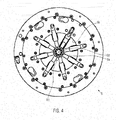
- FIG. 4 a partial view of the expansion unit 6 according to the invention in the inner basic position R1 from above.
- eight expansion segments 6a are provided which abut one another in the basic position R1.
- it would be a different number of Sp Schwarzsegmente 6a conceivable, as is a distance between the Sp Schwarzsegmenten 6a in its basic position R1.
- FIG. 5 shows the spreading unit 6 in the dispensing position R2, in which the radial position of the expansion segments 6a with respect to the central axis 6b 'is preferably not rotationally symmetrical.
- a first group G1 of the expansion segments 6a in the region of the folded edges 2b of the label sleeve 2 is moved farther away from the central axis 6b 'than the expansion segments 6a of the groups G2 and G3 lying between the folded edges 2b.
- the label sleeve 2 can be guided in the region of the fold edges 2b along the respectively adjacent expansion segments 6a and stabilize the label sleeve 2 in the schematically indicated desired dispensing position 13.
- the expansion segments 6a could be subdivided into any groups with different movement sequences, depending on their total number and depending on the shape of the folded edges 2b, provided that the label sleeves 2 can be stabilized in the desired dispensing position 13.
- the distance 14 between opposing expansion elements 6a (or the distance between the expansion elements 6a of the central axis 6b ') in the region of the folded edges 2b is greater than between the other expansion elements 6a.
- the non-rotationally symmetrical dispensing position R2 in particular with respect to the folding edge 2b axisymmetric dispensing position R2, serves for correct alignment of the label sleeve 2 before the subsequent stretching of the label sleeve 2 in the stretched position R3 and the labeling position R4.
- the label sleeve 2 is preferably aligned not only in the desired dispensing position 13 but also in a coaxial position relative to the spreading segments 6a and / or in the lower limit against the spreader unit 6.
- sliding aids 6h can be provided on the expansion segments 6a. These could be, for example, smooth. Suitable are plastics such as PTFE or polished metal surfaces and the like. Also conceivable would be ribbed surfaces. For example, a horizontal corrugation could promote a sliding of the label sleeve 2 in the circumferential direction to adjust their rotational position and at the same time counteract slippage of the label sleeve 2 in the vertical direction.
- FIG. 6 shows the spreader unit 6 in the labeling position R4, in which the radial position of the expansion segments 6a with respect to the central axis 6b 'of the central recess 6b is preferably not rotationally symmetrical.
- a first group G1 'of the expansion segments 6a is moved further away from the central axis 6b' than a second group G2 '.
- the cross section of the label sleeve 2 stretched by the expansion segments 6a can be adapted to the cross section 3a of the container 3 to be labeled.
- the label sleeve 2 is spread, for example, in a rectangular container cross-section 3a to an approximately rectangular cross-section, in an oval container cross-section to an approximately oval cross-section and the like.
- a predetermined distance 15 between the spanned label sleeve 2 and the container 3 in the labeling position R4 and / or in the expansion position R3 is not exceeded. This allows a uniform circumferential expansion of the label sleeve 2 in the transfer to the container 3.
- the distance 15 is preferably not more than 10 mm, in particular at most 5 mm.
- the label sleeve 2 can be aligned in a (schematically indicated) Soll-Etikettierfrontlage 16. As described above for the dispensing rotational position 13, the alignment of the rotational position can be assisted by the sliding aids 6h.
- the container 3 can be forced by means of the non-rotationally symmetrically arranged expansion segments 6a in the labeling position R4 in a correct nominal Etikettiercardlage 16 ', which ideally coincides with the desired Etikettiercard 16 of the label sleeve 2. This may be advantageous after an inadvertent rotation of the container 3 during transport and / or lifting into the expansion unit 6.
- the expansion segments 6a in the outer expansion position R3 of the expansion unit 6 may be arranged non-rotationally symmetrical with respect to the central recess 6b (not shown).
- the container 3 can not only introduce collision-free into the label sleeve 2 but also avoid local overstretching of the label sleeve 2.
- the expansion segments 6a can be moved apart in groups or individually at different speeds and / or with a time offset. This can counteract uneven stretching of the label sleeve 2 to the non-rotationally symmetrical outer expansion position R3 and / or the labeling position R4. In addition, this favors a circumferential slippage of the label sleeve in uneven stretching with the result of a desirable circumferential tension compensation in the label sleeve 2. This protects in particular imprints on the label sleeves 2 in spite of progressive stretching of the label sleeves. 2
Abstract
Description
Die Erfindung betrifft eine Vorrichtung und ein Verfahren zum Etikettieren von Behältern mit insbesondere elastischen Etikettenhülsen.The invention relates to a device and a method for labeling containers with in particular elastic label sleeves.
Behälter, wie beispielsweise Getränkeflaschen, lassen sich unter anderem durch das Aufziehen elastischer Folienhülsen über die Behältermantelfläche etikettieren. Hierzu beschreibt die
In den bekannten Etikettiervorrichtungen können jedoch insbesondere bei der Etikettierung von Behältern mit nichtrotationssymmetrischen Querschnitten die folgenden Probleme auftreten. Das Material der Etikettenhülsen wird beim Aufdehnen in der Spreizeinheit so stark strapaziert, dass das Etikett oder ein auf der Etikettenhülse vorgesehener Aufdruck beschädigt wird. Dies ist beispielsweise der Fall, wenn Etikettenhülsen für Vierkantflaschen rotationssymmetrisch aufgedehnt werden. Die Etikettenhülse muss dann zumindest so weit gedehnt werden, dass die Vierkantflasche in die kreisförmig geöffnete Spreizeinheit passt. Die Etiketten sind nicht mit ausreichender Zuverlässigkeit in der korrekten Drehlage auf den Behältern angebracht. Die Etikettenhülsen können beispielsweise beim Anschlagen gegen die Spreizeinheiten zurückspringen und sich verdrehen.In the known labeling devices, however, the following problems may occur, in particular when labeling containers with non-rotationally symmetrical cross sections. The material of the label sleeves is so much strained during expansion in the spreader unit that the label or provided on the label sleeve imprint is damaged. This is the case, for example, when label sleeves for square bottles are expanded rotationally symmetrically. The label sleeve must then be stretched at least so far that the square bottle fits into the circular open spreader unit. The labels are not affixed with sufficient reliability in the correct rotational position on the containers. The label sleeves, for example, when jumping against the spreader units jump back and twist.
Es besteht somit insgesamt der Bedarf für Etikettiervorrichtungen und Etikettierverfahren für Folienhülsen, insbesondere elastische Etikettenhülsen, bei denen zumindest eines der vorstehend beschriebenen Probleme abgemildert oder beseitigt werden kann.There is thus a general need for labeling devices and labeling methods for film sleeves, in particular elastic label sleeves, in which at least one of the problems described above can be alleviated or eliminated.
Die gestellte Aufgabe wird mit einer Vorrichtung zum Etikettieren von Behältern nach Anspruch 1 gelöst. Neben Spreizeinheiten mit Spreizsegmenten, die von einer inneren Stellung zum Aufnehmen der Etikettenhülsen in eine äußere Stellung zum Spreizen der Etikettenhülsen für das anschließende Etikettieren auseinander bewegbar sind, umfasst die Vorrichtung erfindungsgemäß eine Steuereinrichtung, mit der sich die Spreizsegmente, insbesondere in Gruppen, gleichzeitig oder zeitlich überlappend mit unterschiedlichen Spreizbewegungen beaufschlagen lassen. Dadurch können nichtrotationssymmetrische, insbesondere achsensymmetrische Bewegungsabläufe der Spreizsegmente realisiert werden. Ferner können zeitliche Abläufe und/oder charakteristische Stellungen beim Spreizen an den Querschnitt der aufzunehmenden Etikettenhülsen und/oder den Querschnitt der zu etikettierenden Behälter angepasst werden. Eine gruppenweise Ansteuerung vereinfacht insbesondere die Erzeugung achsensymmetrischer Bewegungsabläufe. Erfindungsgemäße Spreizbewegungen unterscheiden sich beispielsweise hinsichtlich der radialen Endposition der Bewegung, der radialen Stellgeschwindigkeit, der Beschleunigungsrampen und/oder Abbremsrampen, Startzeitpunkt und/oder Stoppzeitpunkt der Bewegung und dergleichen. Die gleichzeitigen oder zeitlich überlappenden Spreizbewegungen beziehen sich auf das gemeinsame Anfahren der Spreizsegmente einer vorgegebenen Stellung der Spreizeinheit. Die Vorrichtung eignet sich insbesondere für elastische Etikettenhülsen, sogenannte Stretch-Sleeves. Allerdings lassen sich auch Schrumpfetiketten mit der erfindungsgemäßen Vorrichtung auf Vierkantflaschen oder anderen nichtrotationssymmetrischen Querschnitten besonders Material schonend aufbringen. Ebenso können auch rotationssymmetrische Behälter mit elastischen oder aufschrumpfbaren Etikettenhülsen besonders exakt in einer vorgegebenen Drehlage etikettiert werden, indem die Drehlage der Etikettenhülsen durch Führen derselben entlang an den Etikettenhülsen vorgesehener Faltkanten stabilisiert wird.The object is achieved with a device for labeling containers according to claim 1. In addition to spreading units with expansion segments, which from an inner position for receiving the label sleeves in an outer position for spreading the label sleeves for subsequent labeling can be moved apart, the device according to the invention comprises a control device with which the expansion segments, in particular in groups, can act simultaneously or temporally overlapping with different spreading movements. As a result, non-rotationally symmetrical, in particular axisymmetric motion sequences of the expansion segments can be realized. Further, temporal processes and / or characteristic positions during spreading to the cross section of the male label sleeves and / or the cross section of the container to be labeled can be adapted. A group-wise control simplifies in particular the generation of axisymmetric motion sequences. Spreading movements according to the invention differ for example with respect to the radial end position of the movement, the radial positioning speed, the acceleration ramps and / or braking ramps, starting time and / or stopping time of the movement and the like. The simultaneous or temporally overlapping expansion movements relate to the common approach of the expansion segments of a predetermined position of the spreading unit. The device is particularly suitable for elastic label sleeves, so-called stretch sleeves. However, shrink labels with the device according to the invention can also be applied to square bottles or other non-rotationally symmetrical cross-sections in a particularly gentle manner. Likewise, rotationally symmetrical containers with elastic or shrink-on label sleeves can be labeled particularly accurately in a predetermined rotational position by the rotational position of the label sleeves is stabilized by guiding the same along the label sleeves provided folding edges.
Vorzugsweise sind die Spreizsegmente um eine zentrale Ausnehmung zum Aufnehmen des Behälters gelagert, insbesondere radial verschiebbar. Ferner lassen sich die Spreizsegmente dann in wenigstens eine bezüglich der zentralen Ausnehmung nichtrotationssymmetrische Stellung bewegen. Dadurch können die Spreizsegmente durch Verschieben sowohl in eine erste, für das Spenden der Etikettenhülsen geeignete Stellung gefahren werden als auch in eine zweite, für die Etikettenübergabe geeignete Stellung. Erfindungsgemäße nichtrotationssymmetrische Stellungen sind beispielsweise Spendestellungen zum Aufnehmen der gespendeten Etikettenhülsen, Dehnstellungen zum Einführen des Behälters in die Etikettenhülsen und Etikettierstellungen zum Übergeben der Etikettenhülsen an die Behälter.Preferably, the expansion segments are mounted around a central recess for receiving the container, in particular radially displaceable. Furthermore, the expansion segments can then move into at least one non-rotationally symmetrical position relative to the central recess. As a result, the expansion segments can be moved by moving both into a first, suitable for donating the label sleeves position and in a second, suitable for the label transfer position. Non-rotationally symmetrical positions according to the invention are, for example, dispensing positions for receiving the donated label sleeves, expansion positions for inserting the container into the label sleeves and labeling positions for transferring the label sleeves to the containers.
Vorzugsweise lassen sich die Spreizsegmente in eine nichtrotationssymmetrische Dehnstellung zum Dehnen der Etikettenhülsen bewegen, die mit einer Solldrehlage des zu etikettierenden Behälters ausgerichtet ist. Dadurch lässt sich die für die Etikettierung notwendige Dehnung der Etikettenhülsen bei nichtrotationssymmetrischen Behälterquerschnitten reduzieren. Vorzugsweise lassen sich die Spreizsegmente in eine nichtrotationssymmetrische Spendestellung zum Aufnehmen und Ausrichten der Etikettenhülsen bewegen, die mit einer Solldrehlage der Etikettenhülse beim Spenden ausgerichtet ist. Dadurch kann die vorgegebene Drehlage der Etikettenhülsen beim Etikettieren genauer eingehalten werden.Preferably, the expansion segments can be moved into a non-rotationally symmetrical expansion position for stretching the label sleeves, which is aligned with a desired rotational position of the container to be labeled. As a result, it is possible to reduce the stretching of the label sleeves necessary for the labeling in the case of non-rotationally symmetrical container cross sections. Preferably, the expansion segments can be moved into a non-rotationally symmetrical dispensing position for receiving and aligning the label sleeves, which is aligned with a desired rotational position of the label sleeve during dispensing. As a result, the predetermined rotational position of the label sleeves during labeling can be maintained more accurately.
Vorzugsweise ist die nichtrotationssymmetrische Spendestellung bezüglich an den Etikettenhülsen ausgebildeter Faltkanten derart ausgerichtet, dass die lichte Weite, oder anders ausgedrückt, der Abstand zwischen einander gegenüber liegenden Spreizsegmenten im Bereich der Faltkanten am größten ist. Insbesondere ist die Spendestellung achsensymmetrisch bezüglich einer gedachten Verbindungslinie zwischen den Faltkanten. Auf diese Weise lässt sich die Drehlage der Etikettenhülsen besonders einfach einstellen und/oder ein Verdrehen der Etikettenhülse auf den Spreizeinheiten vermeiden.Preferably, the non-rotationally symmetrical dispensing position is aligned with respect to folded edges formed on the label sleeves such that the clear width, or in other words, the distance between opposing expansion segments is greatest in the region of the fold edges. In particular, the dispensing position is axisymmetric with respect to an imaginary connecting line between the folded edges. In this way, the rotational position of the label sleeves can be adjusted particularly easily and / or avoid twisting of the label sleeve on the spreader units.
Bei einer besonders günstigen Ausführungsform umfasst die Steuereinrichtung an den Spreizeinheiten vorgesehene Kurvenscheiben mit wenigstens zwei unterschiedlichen Steuerkurven, um die Spreizsegmente bei Drehung der Kurvenscheibe auf unterschiedliche radiale Abstände voneinander weg zu bewegen. Dies ermöglicht eine besonders einfache Umsetzung der Erfindung und/oder ein Nachrüsten herkömmlicher Spreizeinheiten mit der erfindungsgemäßen Ansteuerung durch Austausch der Kurvenscheiben. Die Steuerkurven sind beispielsweise unterschiedlich gekrümmte Steuernuten, in die an den Spreizsegmenten vorgesehene Steuernocken eingreifen.In a particularly favorable embodiment, the control device comprises provided on the spreader units cams with at least two different cams to move the expansion segments on rotation of the cam at different radial distances from each other. This allows a particularly simple implementation of the invention and / or retrofitting conventional spreader units with the control according to the invention by replacing the cams. The cams are, for example, differently curved control grooves, engage in the provided on the expansion segments control cam.
Bei einer weiteren besonders günstigen Ausführungsform sind für die Spreizsegmente individuell ansteuerbare Stellantriebe, insbesondere Elektromotoren vorgesehen. Denkbar sind allerdings ebenso andere individuell ansteuerbare Antriebe, beispielsweise pneumatische Antriebe. Dadurch lassen sich besonders komplexe Bewegungsabläufe realisieren. Außerdem können die Bewegungsabläufe durch Programmierung einfach an unterschiedliche Produktionsbedingungen und/oder Behältertypen und/oder Etikettentypen angepasst werden.In a further particularly favorable embodiment, individually controllable actuators, in particular electric motors, are provided for the expansion segments. Conceivable, however, are also other individually controllable drives, such as pneumatic drives. As a result, particularly complex motion sequences can be realized. In addition, the movements can be easily adapted by programming to different production conditions and / or container types and / or label types.
Vorzugsweise sind an den Spreizsegmenten in umfänglicher Richtung wirkende Gleithilfen für die Etikettenhülsen vorgesehen. Dadurch lassen sich ungleichmäßige Spannungen und Dehnung der Etikettenhülsen reduzieren.Preferably, sliding aids for the label sleeves are provided on the expansion segments in the circumferential direction. This can reduce uneven tension and elongation of the label sleeves.
Die gestellte Aufgabe wird ferner gelöst mit einem Verfahren zum Etikettieren von Behältern nach Anspruch 9. Diese eignet sich insbesondere für elastische Etikettenhülsen, beispielsweise bestehend aus dem Grundmaterial LDPE. Demnach werden die Etikettenhülsen auf Spreizeinheiten mit Spreizsegmenten geschossen die Etikettenhülsen für die nachfolgende Etikettierung durch Auseinanderfahren der Spreizsegmente gespreizt. Erfindungsgemäß werden die Spreizsegmente, insbesondere in Gruppen, gleichzeitig oder zeitlich überlappend mit unterschiedlichen Spreizbewegungen beaufschlagt.The stated object is further achieved with a method for labeling containers according to
Vorzugsweise werden die Spreizbewegungen an den Querschnitt der Behälter und/oder die Solldrehlage der Behälter beim Etikettieren angepasst. Beispielsweise werden die Etikettenhülsen bei polygonalen Behälterquerschnitten auf einen näherungsweise entsprechenden polygonalen Querschnitt gespreizt. Entsprechendes gilt für ovale, elliptische Querschnitte und Kombinationen der genannten Grundformen. Dadurch lässt sich eine Überdehnung der Etikettenhülsen vermeiden, insbesondere eine Schädigung von Aufdrucken auf den Etikettenhülsen.Preferably, the spreading movements are adapted to the cross section of the container and / or the desired rotational position of the container during labeling. For example, the label sleeves are spread in polygonal container cross-sections to an approximately corresponding polygonal cross-section. The same applies to oval, elliptical cross-sections and combinations of the basic forms mentioned. As a result, an overstretching of the label sleeves can be avoided, in particular damage to imprints on the label sleeves.
Vorzugsweise werden die Spreizsegmente in eine nichtrotationssymmetrische Dehnstellung zum Dehnen der Etikettenhülsen bewegt, die an den Querschnitt des Behälters derart angepasst ist, dass der Abstand zwischen den Spreizsegmenten und dem Behälter höchstens 10 mm beträgt, insbesondere höchstens 5 mm. Dadurch lässt sich die Etikettenhülse besonders schonend und genau aufbringen. Insbesondere kann die Etikettenhülse gleichmäßig auf den gewünschten Querschnitt gedehnt werden, so dass Verzerrungen und/oder Beschädigungen beim anschließenden Übergeben der Etikettenhülse an den Behälter minimiert werden.Preferably, the expansion segments are moved to a non-rotationally symmetrical expansion position for stretching the label sleeves, which is adapted to the cross section of the container such that the distance between the expansion segments and the container is at most 10 mm, in particular at most 5 mm. As a result, the label sleeve can be particularly gently and accurately apply. In particular, the label sleeve can be stretched uniformly to the desired cross-section so that distortions and / or damage during the subsequent transfer of the label sleeve to the container are minimized.
Vorzugsweise werden die Spreizbewegungen für das Spenden der Etikettenhülsen an die Drehlage der Etikettenhülsen angepasst. Da die Etikettenhülsen beim Spenden in der Regel nicht rotationssymmetrisch, also mit kreisrundem Querschnitt, geöffnet sind und Faltkanten aufweisen, kann die Drehlage beim Spenden durch nichtrotationssymmetrisches Auseinanderfahren der Spreizsegmente stabilisiert und ein Zurückspringen und Verdrehen der Etikettenhülsen von den Spreizeinheiten vermieden werden.Preferably, the spreading movements for dispensing the label sleeves are adapted to the rotational position of the label sleeves. Since the label sleeves are usually not rotationally symmetrical, ie circular in cross-section, and have folded edges during dispensing, the rotational position during dispensing can be stabilized by non-rotationally symmetrical separation of the expansion segments and springing back and twisting of the label sleeves away from the spreader units.
Vorzugsweise werden die Spreizbewegungen derart angepasst, dass wenigstens zwei Spreizsegmente die Etikettenhülsen entlang an den Etikettenhülsen vorgesehener Faltkanten führen. Dies ermöglicht eine besonders präzise Ausrichtung und/oder Stabilisierung der Drehlage.Preferably, the spreading movements are adapted such that at least two expansion segments guide the label sleeves along the label sleeves provided folding edges. This allows a particularly precise alignment and / or stabilization of the rotational position.
Vorzugsweise werden die Spreizsegmente unterschiedlich schnell und/oder zeitlich versetzt auseinander gefahren. Dadurch lassen sich komplexe Bewegungsabläufe realisieren für das Spenden und Dehnen der Etikettenhülsen kombinieren. Außerdem kann einem lokalen Überdehnen der Etikettenhülsen entgegen gewirkt werden.Preferably, the expansion segments are moved apart at different speeds and / or with a time offset. As a result, complex sequences of movements can be combined for donating and stretching the label sleeves. In addition, a local overstretching of the label sleeves can be counteracted.
Vorzugsweise haben die Behälter einen nichtrotationssymmetrischen Querschnitt. Besonders geeignet sind polygonale Querschnitte mit abgerundeten Ecken, elliptische Querschnitte und Kombinationen daraus.Preferably, the containers have a non-rotationally symmetrical cross-section. Particularly suitable are polygonal cross sections with rounded corners, elliptical cross sections and combinations thereof.
Eine bevorzugte Ausführungsform der erfindungsgemäßen Vorrichtung ist in der Zeichnung dargestellt. Es zeigen:
- Fig. 1
- eine Draufsicht auf eine erfindungsgemäße Etikettiervorrichtung;
- Fig. 2
- eine schematische Darstellung charakteristischer Betriebszustände einer Etikettierstation der erfindungsgemäßen Etikettiervorrichtung;
- Fig. 3
- eine erfindungsgemäße Spreizeinheit;
- Fig. 4
- eine Draufsicht auf die Spreizsegmente der Spreizeinheit in einer inneren Grundstellung;
- Fig. 5
- eine Draufsicht auf die Spreizsegmente der Spreizeinheit und eine schematisch angedeutete Etikettenhülse in einer erfindungsgemäßen Spendestellung; und
- Fig. 6
- eine Draufsicht auf die Spreizsegmente, eine schematisch angedeutete Etikettenhülse und einen Behälter in einer erfindungsgemäßen Etikettierstellung.
- Fig. 1
- a plan view of a labeling device according to the invention;
- Fig. 2
- a schematic representation of characteristic operating conditions of a labeling station of the labeling device according to the invention;
- Fig. 3
- a spreader unit according to the invention;
- Fig. 4
- a plan view of the expansion segments of the spreading unit in an inner basic position;
- Fig. 5
- a plan view of the expansion segments of the spreading unit and a schematically indicated label sleeve in a dispensing position according to the invention; and
- Fig. 6
- a plan view of the expansion segments, a schematically indicated label sleeve and a container in a labeling according to the invention.
Wie die
In der
Demnach befindet sich die umlaufende Etikettierstation 5 an der Position I im Bereich des stationären Etikettenspenders 10. An der Spreizeinheit 6 sind mehrere bewegliche Spreizsegmente 6a um eine zentrale Ausnehmung 6b herum angeordnet. Beim Spenden sind die Spreizsegmente 6a anfänglich in einer inneren Grundstellung R1, so dass sie eine von dem Etikettenspender 10 gespendete Etikettenhülse 2 auffangen und mitnehmen können. Hierbei werden die Etikettenhülsen 2 in bekannter Weise von einem ursprünglich flach gefalteten und über einen Dorn gezogenen Folienschlauch 2a abgetrennt und mittels schematisch angedeuteter Transportrollen 10a von oben über die vorbei laufenden Spreizsegmente 6a geschossen.Accordingly, the circulating
An der Position II ist die Etikettenhülse 2 um die Spreizsegmente 6a positioniert, wobei diese in eine vorzugsweise asymmetrische Spendestellung R2 auseinander gefahren sind, um die Etikettenhülse 2 in einer Soll-Spendedrehlage 13 zu stabilisieren und ferner ein Zurückspringen der Etikettenhülse 2 von der Spreizeinheit 6 zu vermeiden. Die Soll-Spendedrehlage 13 der Etikettenhülse 2 ist im Wesentlichen durch die Orientierung des Folienschlauchs 2a im Etikettenspender 10 vorgegeben und durch die Lage der Faltkanten 2b des Folienschlauchs 2a charakterisiert. Die Faltkanten 2b bleiben im ungedehnten Zustand der Etikettenhülse 2 sichtbar und verursachen einen in Richtung der Faltkanten 2b gestreckten Querschnitt der Etikettenhülse 2, wie aus der
An der Position III ist die Spreizeinheit 6 beim Spreizen der Etikettenhülse 2 in einer Zwischenstellung gezeigt, bei der alle Spreizsegmente 6a an der Etikettenhülse 2 anliegen. Diese kann in der Folge von den Spreizsegmenten 6a angesaugt werden, um die Lage der Etikettenhülse 2 auf der Spreizeinheit 6 beim weiteren Spreizen und Dehnen zu stabilisieren. Der Behälter 3 wird zudem von schwenkbaren Führungsschalen 7a im Bereich der Positioniereinheit 7 stehend seitlich umschlossen, um den Behälter 3 von dem Einlaufsternrad 11 an die Positioniereinheit 7 zu übernehmen.At position III, the spreading
An der Position IV hat die Etikettierstation 5 den Bereich des Einlaufsternrads 11 verlassen. Ferner sind die Spreizsegmente 6a in einer äußeren Dehnstellung R3 gezeigt, bei der die Etikettenhülse 2 soweit aufgedehnt ist, dass der zu etikettierende Behälter 3 mit Hilfe der Positioniereinheit 7 durch die zentrale Ausnehmung 6b in die Spreizeinheit 6 angehoben werden kann. Die Hubbewegung 7a der Positioniereinheit 7 ist an der Position V schematisch angedeutet, das Erreichen einer oberen Endposition zur nachfolgenden Etikettenübergabe an der Position IV.At position IV, the
An der Position VII ist die Spreizeinheit 6 in einer Etikettierstellung R4, bei der die Spreizsegmente 6a zur nachfolgenden Übergabe der Etikettenhülse 2 an den Behälter 3 heran gefahren sind. Ferner greift eine an der Entnahmeeinheit 8 vorgesehene Klammer 8a den mündungsseitigen Abschnitt des Behälters 3, so dass der Behälter 3 nachfolgend mittels der Entnahmeeinheit 8 angehoben werden kann. Die zugehörige Hubbewegung ist an der Position VII durch einen Pfeil angedeutet. Beim Herausziehen des Behälters wird in bekannter Weise ein Überdruck an die Spreizsegmente 6a angelegt, um die Etikettenübergabe mit Hilfe eines Druckluftkissens zwischen den Spreizsegmenten 6a und der Etikettenhülse 2 zu erleichtern. Ferner könnten an der Entnahmeeinheit 8 zusätzliche Klemmbacken oder dergleichen vorgesehen sein, um den Reibschluss zwischen der Etikettenhülse 2 und dem Behälter 3 zu unterstützen und/oder herzustellen.At position VII, the spreading
Die Position VIII zeigt den etikettierten nach dem Herausziehen aus der Spreizeinheit 6 und bei der Übergabe an den Auslaufstern 12.The position VIII shows the labeled after pulling out of the spreading
In der
Die Steuerscheibe 6e dient zur gemeinsamen Steuerung der Spreizsegmente 6a. Zu diesem Zweck sind die Steuernuten 6f derart ausgebildet, dass die Spreizsegmente 6a bei Drehung der der Steuerscheibe unterschiedlich weit von der zentralen Ausnehmung 6b weg bewegt werden. Dazu sind vorzugsweise gekrümmte Steuernuten 6f mit unterschiedlichen Kurvenverläufen vorgesehen, in den die Spreizsegmente 6a jeweils mittels Steuernocken geführt sind. Die Spreizsegmente 6a sind hierbei vorzugsweise radial beweglich gelagert, so dass die Drehung der Steuerscheibe 6e entlang der unterschiedlichen Steuernuten 6f gleichzeitig unterschiedliche radiale Bewegungsmuster der zugeordneten Spreizsegmente 6a erzeugen.The
An Stelle des gemeinsamen Antriebsmotors 6c für die Spreizsegmente 6a und der gemeinsamen Steuerscheibe 6e könnten auch individuelle Antriebsmotoren (nicht gezeigt) für die Spreizsegmente 6a vorgesehen sein, um die erfindungsgemäßen Stellungen der Spreizsegmente 6a zu erzeugen. Die Steuereinrichtung 9 ist dann entsprechend zur koordinierten Ansteuerung der individuellen Antriebsmotoren ausgebildet. Mit Hilfe individuell ansteuerbarer Antriebsmotoren für einzelne Spreizsegmente 6a lassen sich besonders komplexe zeitliche Bewegungsabläufe der Spreizsegmente 6a realisieren und/oder durch Programmierung der Steuereinheit 9 flexibel anpassen.Instead of the common drive motor 6c for the
Die
Anhand der
Demnach zeigt die
Die
Wünschenswert ist ferner ein Abbremsen und/oder Verankern der Etikettenhülsen 2 an den Spreizsegmenten 6a, um ein Zurückspringen der Etikettenhülsen 2 nach dem Anschlagen gegen die Spreizeinheit 6 zu vermeiden. Dies kann durch ein geeignetes Auseinanderfahren der Spreizsegmente 6a der in der
Die nichtrotationssymmetrische Spendestellung R2, insbesondere eine bezüglich der Faltkante 2b achsensymmetrische Spendestellung R2, dient einer korrekten Ausrichtung der Etikettenhülse 2 vor dem anschließenden Dehnen der Etikettenhülse 2 in die Dehnstellung R3 und die Etikettierstellung R4. Die Etikettenhülse 2 wird in der Spendestellung R2 vorzugsweise nicht nur in der Soll-Spendedrehlage 13 ausgerichtet sondern auch in einer koaxiale Lage bezüglich der Spreizsegmente 6a und/oder im unteren Anschlag gegen die Spreizeinheit 6.The non-rotationally symmetrical dispensing position R2, in particular with respect to the
Um die Etikettenhülse 2 um die Spreizsegmente 6a in geeigneter Weise auszurichten, können Gleithilfen 6h an den Spreizsegmenten 6a vorgesehen sein. Diese könnten beispielsweise glattflächig sein. Geeignet sind Kunststoffe, wie beispielsweise PTFE, oder polierte Metalloberflächen und dergleichen. Denkbar wären auch geriffelte Oberflächen. Beispielsweise könnte eine horizontale Riffelung ein Gleiten der Etikettenhülse 2 in umfänglicher Richtung zum Anpassen ihrer Drehlage begünstigen und gleichzeitig einem Verrutschen der Etikettenhülse 2 in vertikaler Richtung entgegen wirken.In order to align the
Die
Dadurch lässt sich der Querschnitt der von den Spreizsegmenten 6a gedehnten Etikettenhülse 2 an den Querschnitt 3a des zu etikettierenden Behälters 3 anpassen. Darunter ist zu verstehen, dass die Etikettenhülse 2 beispielsweise bei einem rechteckigen Behälterquerschnitt 3a auf einen näherungsweise rechteckigen Querschnitt gespreizt wird, bei einem ovalen Behälterquerschnitt auf einen näherungsweise ovalen Querschnitt und dergleichen. Dies gilt ebenso für polygonale Querschnitte mit abgerundeten Ecken und dergleichen. Vorzugsweise wird ein vorgegebener Abstand 15 zwischen der aufgespannten Etikettenhülse 2 und dem Behälter 3 in der Etikettierstellung R4 und/oder in der Dehnstellung R3 nicht überschritten. Dies ermöglicht eine gleichmäßige umfängliche Dehnung der Etikettenhülse 2 bei der Übergabe an den Behälter 3. Der Abstand 15 beträgt vorzugsweise nicht mehr als 10 mm, insbesondere höchstens 5 mm. Außerdem kann die Etikettenhülse 2 in eine (schematisch angedeutete) Soll-Etikettierdrehlage 16 ausgerichtet werden. Wie vorstehend für die Spende-Drehlage 13 beschrieben ist, kann das Ausrichten der Drehlage durch die Gleithilfen 6h unterstützt werden. Außerdem kann der Behälter 3 mit Hilfe der nichtrotationssymmetrisch angeordneten Spreizsegmente 6a in der Etikettierstellung R4 in eine korrekte Soll-Etikettierdrehlage 16' gezwungen werden, die idealer Weise mit der Soll-Etikettierdrehlage 16 der Etikettenhülse 2 übereinstimmt. Dies kann nach einem unabsichtlichen Verdrehen des Behälters 3 beim Transportieren und/oder Anheben in die Spreizeinheit 6 vorteilhaft sein.As a result, the cross section of the
In vergleichbarer Weise können die Spreizsegmente 6a in der äußeren Dehnstellung R3 der Spreizeinheit 6 nichtrotationssymmetrisch bezüglich der zentralen Ausnehmung 6b angeordnet sein (nicht gezeigt). Dadurch lässt sich der Behälter 3 nicht nur kollisionsfrei in die Etikettenhülse 2 einführen sondern auch eine lokale Überdehnung der Etikettenhülse 2 vermeiden.In a comparable manner, the
Um ein Überdehnen zu vermeiden, können die Spreizsegmente 6a gruppenweise oder einzeln mit unterschiedlichen Geschwindigkeiten und/oder zeitlich versetzt auseinander gefahren werden. Dies kann einer ungleichmäßigen Dehnung der Etikettenhülse 2 auf die nichtrotationssymmetrische äußere Dehnstellung R3 und/oder die Etikettierstellung R4 entgegen wirken. Außerdem begünstigt dies ein umfängliches Nachrutschen der Etikettenhülse bei ungleichmäßiger Dehnung mit der Folge eines wünschenswerten umfänglichen Spannungsausgleichs in der Etikettenhülse 2. Dies schont insbesondere Aufdrucke auf den Etikettenhülsen 2 trotz fortschreitender Dehnung der Etikettenhülsen 2.In order to avoid overstretching, the
Claims (15)
gekennzeichnet durch
eine Steuereinrichtung (9), mit der sich die Spreizsegmente, insbesondere in Gruppen (G1 - G3, G1', G2'), gleichzeitig oder zeitlich überlappend mit unterschiedlichen Spreizbewegungen beaufschlagen lassen.Device for labeling containers (3), in particular with elastic label sleeves (2), comprising spreading units (6) with expanding segments (6a), which extend from an inner position (R1) for receiving the label sleeves to an outer position (R3, R4) for spreading the label sleeves are movable apart for the subsequent labeling,
marked by
a control device (9) with which the expansion segments, in particular in groups (G1 - G3, G1 ', G2'), can be subjected to different expansion movements simultaneously or overlapping in time.
dadurch gekennzeichnet, dass
die Spreizsegmente, insbesondere in Gruppen (G1 - G3, G1', G2'), gleichzeitig oder zeitlich überlappend mit unterschiedlichen Spreizbewegungen beaufschlagt werden.Method for labeling containers (3) with, in particular, elastic label sleeves (2), in which the label sleeves are spread on spreading units (6) with expansion segments (6a), and in which the label sleeves are spread for the subsequent labeling by moving apart the expansion segments,
characterized in that
the expansion segments, in particular in groups (G1 - G3, G1 ', G2'), are acted on at the same time or overlapping in time with different spreading movements.
Applications Claiming Priority (1)
| Application Number | Priority Date | Filing Date | Title |
|---|---|---|---|
| DE102011087729A DE102011087729A1 (en) | 2011-12-05 | 2011-12-05 | Apparatus and method for labeling containers with elastic label sleeves |
Publications (2)
| Publication Number | Publication Date |
|---|---|
| EP2602199A1 true EP2602199A1 (en) | 2013-06-12 |
| EP2602199B1 EP2602199B1 (en) | 2015-04-22 |
Family
ID=47191524
Family Applications (1)
| Application Number | Title | Priority Date | Filing Date |
|---|---|---|---|
| EP20120190169 Active EP2602199B1 (en) | 2011-12-05 | 2012-10-26 | Method and device for labelling containers with stretch sleeves |
Country Status (3)
| Country | Link |
|---|---|
| EP (1) | EP2602199B1 (en) |
| CN (1) | CN103129789B (en) |
| DE (1) | DE102011087729A1 (en) |
Families Citing this family (1)
| Publication number | Priority date | Publication date | Assignee | Title |
|---|---|---|---|---|
| CN113870658B (en) * | 2021-10-20 | 2023-08-11 | 钟妙红 | Twenty-four solar terms cognitive teaching equipment used in kindergarten and use method thereof |
Citations (4)
| Publication number | Priority date | Publication date | Assignee | Title |
|---|---|---|---|---|
| WO1996040559A2 (en) * | 1995-06-07 | 1996-12-19 | B & H Manufacturing Co., Inc. | Computer controlled labeling machine |
| WO2008076718A1 (en) | 2006-12-15 | 2008-06-26 | Ccl Label Gmbh | Stretch film sleeve label applicator |
| EP2199219A2 (en) * | 2008-12-19 | 2010-06-23 | Krones AG | Tensioning device and use of same for labelling objects, method for labelling objects |
| EP2316738A2 (en) * | 2009-11-02 | 2011-05-04 | Leo Bühler | Stretch sleeve labelling |
Family Cites Families (10)
| Publication number | Priority date | Publication date | Assignee | Title |
|---|---|---|---|---|
| US2884328A (en) * | 1954-09-16 | 1959-04-28 | Union Carbide Corp | Method of and apparatus for producing a tightly packaged food product |
| US3974628A (en) * | 1975-11-11 | 1976-08-17 | Anatole Ethan Konstantin | Banding machine |
| FR2471851A1 (en) * | 1979-12-19 | 1981-06-26 | Fresnel Jacques | Appts. for automatic manipulation of tubular packaging film - with cam mechanisms interchangeable to suit different sleeve or pack formats |
| NL9401561A (en) * | 1994-09-26 | 1996-05-01 | Terpo Holding Bv | Elastic chain, method and device for manufacturing an elastic chain, and method and device for supplying elastics originating from the elastic chain to a treatment device. |
| JP4306867B2 (en) * | 1999-04-06 | 2009-08-05 | 株式会社フジシールインターナショナル | Label mounting device |
| US6543514B2 (en) * | 1999-04-21 | 2003-04-08 | Axon Corporation | In-line continuous feed sleeve labeling machine and method |
| ES2241601T3 (en) * | 1999-04-30 | 2005-11-01 | Krones Ag | PROCEDURE AND DEVICE FOR APPLYING TUBULAR LABELS ON OBJECTS. |
| ITBO20040253A1 (en) * | 2004-04-23 | 2004-07-23 | Aetna Group Spa | MACHINE FOR THE PACKAGING OF GROUPS OF PRODUCTS BY TUBULAR ELEMENTS OF ELASTIC FILM |
| DE102009047463A1 (en) * | 2009-12-03 | 2011-06-09 | Krones Ag | Device and method for applying a label sleeve |
| DE102011002788A1 (en) * | 2011-01-17 | 2012-07-19 | Krones Aktiengesellschaft | Apparatus and method for attaching elastic film sleeves to containers |
-
2011
- 2011-12-05 DE DE102011087729A patent/DE102011087729A1/en not_active Withdrawn
-
2012
- 2012-10-26 EP EP20120190169 patent/EP2602199B1/en active Active
- 2012-12-05 CN CN201210517571.3A patent/CN103129789B/en active Active
Patent Citations (4)
| Publication number | Priority date | Publication date | Assignee | Title |
|---|---|---|---|---|
| WO1996040559A2 (en) * | 1995-06-07 | 1996-12-19 | B & H Manufacturing Co., Inc. | Computer controlled labeling machine |
| WO2008076718A1 (en) | 2006-12-15 | 2008-06-26 | Ccl Label Gmbh | Stretch film sleeve label applicator |
| EP2199219A2 (en) * | 2008-12-19 | 2010-06-23 | Krones AG | Tensioning device and use of same for labelling objects, method for labelling objects |
| EP2316738A2 (en) * | 2009-11-02 | 2011-05-04 | Leo Bühler | Stretch sleeve labelling |
Also Published As
| Publication number | Publication date |
|---|---|
| CN103129789A (en) | 2013-06-05 |
| CN103129789B (en) | 2015-09-16 |
| EP2602199B1 (en) | 2015-04-22 |
| DE102011087729A1 (en) | 2013-06-06 |
Similar Documents
| Publication | Publication Date | Title |
|---|---|---|
| EP2476620B1 (en) | Method and device for fixing elastic sleeves onto containers | |
| EP1858689B1 (en) | Device for the blow-moulding of containers | |
| DE102008046366A1 (en) | Centering unit for aligning at least two grouped vessels and method for aligning two grouped vessels | |
| EP2734463B1 (en) | Module for aligning containers and method for aligning containers | |
| DE102010001184A1 (en) | Labeling apparatus and method for labeling plastic bottles in a blow mold, in particular in a rotary machine | |
| WO2003051751A1 (en) | Device for producing foil rolls | |
| EP1396433B1 (en) | Device for a sleeve label applying machine | |
| EP2602198B1 (en) | Method and device for labelling containers with stretch sleeves | |
| DE19716079A1 (en) | Method of labelling bottles | |
| DE102011087722A1 (en) | Apparatus and method for labeling containers with label sleeves | |
| EP1980509A2 (en) | Container handling machine | |
| DE102018217776A1 (en) | Graduation change star for transporting and transferring containers | |
| EP1773571B1 (en) | Method and device for blow moulding containers | |
| EP2602199B1 (en) | Method and device for labelling containers with stretch sleeves | |
| DE202015103890U1 (en) | Variable lift curve | |
| EP2602202B1 (en) | Method and device for labelling containers with stretch sleeves | |
| DE102010002246A1 (en) | Apparatus and method for producing labeled plastic containers | |
| DE102017208501A1 (en) | Wrapping module for a packaging system, packaging system with such a winding module and method for applying a stream of articles with stretchable film | |
| DE102013108184B3 (en) | Winding machine for manufacturing wire core for tire of vehicle, has transportation drive that is provided for driving escapement wheel and is synchronized with winding drive of winding pulley used to roll winding material to wire core | |
| EP2602197B1 (en) | Device for labelling containers with stretch sleeves | |
| EP2380676A1 (en) | Method for operating a bending machine with movable straightening unit | |
| EP1270425B1 (en) | Method and device for applying tubular labels to articles | |
| EP2602201B1 (en) | Method for labelling containers with stretch sleeves | |
| DE1908526A1 (en) | Take-up device | |
| EP2610185B1 (en) | Method and device for labelling containers with sleeve-labels |
Legal Events
| Date | Code | Title | Description |
|---|---|---|---|
| PUAI | Public reference made under article 153(3) epc to a published international application that has entered the european phase |
Free format text: ORIGINAL CODE: 0009012 |
|
| AK | Designated contracting states |
Kind code of ref document: A1 Designated state(s): AL AT BE BG CH CY CZ DE DK EE ES FI FR GB GR HR HU IE IS IT LI LT LU LV MC MK MT NL NO PL PT RO RS SE SI SK SM TR |
|
| AX | Request for extension of the european patent |
Extension state: BA ME |
|
| 17P | Request for examination filed |
Effective date: 20131128 |
|
| RBV | Designated contracting states (corrected) |
Designated state(s): AL AT BE BG CH CY CZ DE DK EE ES FI FR GB GR HR HU IE IS IT LI LT LU LV MC MK MT NL NO PL PT RO RS SE SI SK SM TR |
|
| 17Q | First examination report despatched |
Effective date: 20140428 |
|
| GRAP | Despatch of communication of intention to grant a patent |
Free format text: ORIGINAL CODE: EPIDOSNIGR1 |
|
| INTG | Intention to grant announced |
Effective date: 20141118 |
|
| GRAS | Grant fee paid |
Free format text: ORIGINAL CODE: EPIDOSNIGR3 |
|
| GRAA | (expected) grant |
Free format text: ORIGINAL CODE: 0009210 |
|
| AK | Designated contracting states |
Kind code of ref document: B1 Designated state(s): AL AT BE BG CH CY CZ DE DK EE ES FI FR GB GR HR HU IE IS IT LI LT LU LV MC MK MT NL NO PL PT RO RS SE SI SK SM TR |
|
| REG | Reference to a national code |
Ref country code: GB Ref legal event code: FG4D Free format text: NOT ENGLISH |
|
| REG | Reference to a national code |
Ref country code: CH Ref legal event code: EP |
|
| REG | Reference to a national code |
Ref country code: AT Ref legal event code: REF Ref document number: 723068 Country of ref document: AT Kind code of ref document: T Effective date: 20150515 |
|
| REG | Reference to a national code |
Ref country code: IE Ref legal event code: FG4D Free format text: LANGUAGE OF EP DOCUMENT: GERMAN |
|
| REG | Reference to a national code |
Ref country code: DE Ref legal event code: R096 Ref document number: 502012002907 Country of ref document: DE Effective date: 20150603 |
|
| REG | Reference to a national code |
Ref country code: NL Ref legal event code: VDEP Effective date: 20150422 |
|
| REG | Reference to a national code |
Ref country code: LT Ref legal event code: MG4D |
|
| PG25 | Lapsed in a contracting state [announced via postgrant information from national office to epo] |
Ref country code: NL Free format text: LAPSE BECAUSE OF FAILURE TO SUBMIT A TRANSLATION OF THE DESCRIPTION OR TO PAY THE FEE WITHIN THE PRESCRIBED TIME-LIMIT Effective date: 20150422 |
|
| PG25 | Lapsed in a contracting state [announced via postgrant information from national office to epo] |
Ref country code: PT Free format text: LAPSE BECAUSE OF FAILURE TO SUBMIT A TRANSLATION OF THE DESCRIPTION OR TO PAY THE FEE WITHIN THE PRESCRIBED TIME-LIMIT Effective date: 20150824 Ref country code: HR Free format text: LAPSE BECAUSE OF FAILURE TO SUBMIT A TRANSLATION OF THE DESCRIPTION OR TO PAY THE FEE WITHIN THE PRESCRIBED TIME-LIMIT Effective date: 20150422 Ref country code: LT Free format text: LAPSE BECAUSE OF FAILURE TO SUBMIT A TRANSLATION OF THE DESCRIPTION OR TO PAY THE FEE WITHIN THE PRESCRIBED TIME-LIMIT Effective date: 20150422 Ref country code: ES Free format text: LAPSE BECAUSE OF FAILURE TO SUBMIT A TRANSLATION OF THE DESCRIPTION OR TO PAY THE FEE WITHIN THE PRESCRIBED TIME-LIMIT Effective date: 20150422 Ref country code: NO Free format text: LAPSE BECAUSE OF FAILURE TO SUBMIT A TRANSLATION OF THE DESCRIPTION OR TO PAY THE FEE WITHIN THE PRESCRIBED TIME-LIMIT Effective date: 20150722 Ref country code: FI Free format text: LAPSE BECAUSE OF FAILURE TO SUBMIT A TRANSLATION OF THE DESCRIPTION OR TO PAY THE FEE WITHIN THE PRESCRIBED TIME-LIMIT Effective date: 20150422 |
|
| PG25 | Lapsed in a contracting state [announced via postgrant information from national office to epo] |
Ref country code: IS Free format text: LAPSE BECAUSE OF FAILURE TO SUBMIT A TRANSLATION OF THE DESCRIPTION OR TO PAY THE FEE WITHIN THE PRESCRIBED TIME-LIMIT Effective date: 20150822 Ref country code: RS Free format text: LAPSE BECAUSE OF FAILURE TO SUBMIT A TRANSLATION OF THE DESCRIPTION OR TO PAY THE FEE WITHIN THE PRESCRIBED TIME-LIMIT Effective date: 20150422 Ref country code: GR Free format text: LAPSE BECAUSE OF FAILURE TO SUBMIT A TRANSLATION OF THE DESCRIPTION OR TO PAY THE FEE WITHIN THE PRESCRIBED TIME-LIMIT Effective date: 20150723 Ref country code: LV Free format text: LAPSE BECAUSE OF FAILURE TO SUBMIT A TRANSLATION OF THE DESCRIPTION OR TO PAY THE FEE WITHIN THE PRESCRIBED TIME-LIMIT Effective date: 20150422 |
|
| REG | Reference to a national code |
Ref country code: DE Ref legal event code: R097 Ref document number: 502012002907 Country of ref document: DE |
|
| PG25 | Lapsed in a contracting state [announced via postgrant information from national office to epo] |
Ref country code: DK Free format text: LAPSE BECAUSE OF FAILURE TO SUBMIT A TRANSLATION OF THE DESCRIPTION OR TO PAY THE FEE WITHIN THE PRESCRIBED TIME-LIMIT Effective date: 20150422 Ref country code: EE Free format text: LAPSE BECAUSE OF FAILURE TO SUBMIT A TRANSLATION OF THE DESCRIPTION OR TO PAY THE FEE WITHIN THE PRESCRIBED TIME-LIMIT Effective date: 20150422 |
|
| PLBE | No opposition filed within time limit |
Free format text: ORIGINAL CODE: 0009261 |
|
| STAA | Information on the status of an ep patent application or granted ep patent |
Free format text: STATUS: NO OPPOSITION FILED WITHIN TIME LIMIT |
|
| PG25 | Lapsed in a contracting state [announced via postgrant information from national office to epo] |
Ref country code: SK Free format text: LAPSE BECAUSE OF FAILURE TO SUBMIT A TRANSLATION OF THE DESCRIPTION OR TO PAY THE FEE WITHIN THE PRESCRIBED TIME-LIMIT Effective date: 20150422 Ref country code: CZ Free format text: LAPSE BECAUSE OF FAILURE TO SUBMIT A TRANSLATION OF THE DESCRIPTION OR TO PAY THE FEE WITHIN THE PRESCRIBED TIME-LIMIT Effective date: 20150422 Ref country code: RO Free format text: LAPSE BECAUSE OF NON-PAYMENT OF DUE FEES Effective date: 20150422 Ref country code: PL Free format text: LAPSE BECAUSE OF FAILURE TO SUBMIT A TRANSLATION OF THE DESCRIPTION OR TO PAY THE FEE WITHIN THE PRESCRIBED TIME-LIMIT Effective date: 20150422 |
|
| 26N | No opposition filed |
Effective date: 20160125 |
|
| PG25 | Lapsed in a contracting state [announced via postgrant information from national office to epo] |
Ref country code: LU Free format text: LAPSE BECAUSE OF FAILURE TO SUBMIT A TRANSLATION OF THE DESCRIPTION OR TO PAY THE FEE WITHIN THE PRESCRIBED TIME-LIMIT Effective date: 20151026 Ref country code: SI Free format text: LAPSE BECAUSE OF FAILURE TO SUBMIT A TRANSLATION OF THE DESCRIPTION OR TO PAY THE FEE WITHIN THE PRESCRIBED TIME-LIMIT Effective date: 20150422 |
|
| REG | Reference to a national code |
Ref country code: CH Ref legal event code: PL |
|
| PG25 | Lapsed in a contracting state [announced via postgrant information from national office to epo] |
Ref country code: MC Free format text: LAPSE BECAUSE OF FAILURE TO SUBMIT A TRANSLATION OF THE DESCRIPTION OR TO PAY THE FEE WITHIN THE PRESCRIBED TIME-LIMIT Effective date: 20150422 |
|
| REG | Reference to a national code |
Ref country code: IE Ref legal event code: MM4A |
|
| PG25 | Lapsed in a contracting state [announced via postgrant information from national office to epo] |
Ref country code: LI Free format text: LAPSE BECAUSE OF NON-PAYMENT OF DUE FEES Effective date: 20151031 Ref country code: CH Free format text: LAPSE BECAUSE OF NON-PAYMENT OF DUE FEES Effective date: 20151031 |
|
| REG | Reference to a national code |
Ref country code: FR Ref legal event code: PLFP Year of fee payment: 5 |
|
| PG25 | Lapsed in a contracting state [announced via postgrant information from national office to epo] |
Ref country code: IE Free format text: LAPSE BECAUSE OF NON-PAYMENT OF DUE FEES Effective date: 20151026 |
|
| PG25 | Lapsed in a contracting state [announced via postgrant information from national office to epo] |
Ref country code: HU Free format text: LAPSE BECAUSE OF FAILURE TO SUBMIT A TRANSLATION OF THE DESCRIPTION OR TO PAY THE FEE WITHIN THE PRESCRIBED TIME-LIMIT; INVALID AB INITIO Effective date: 20121026 Ref country code: BG Free format text: LAPSE BECAUSE OF FAILURE TO SUBMIT A TRANSLATION OF THE DESCRIPTION OR TO PAY THE FEE WITHIN THE PRESCRIBED TIME-LIMIT Effective date: 20150422 Ref country code: SM Free format text: LAPSE BECAUSE OF FAILURE TO SUBMIT A TRANSLATION OF THE DESCRIPTION OR TO PAY THE FEE WITHIN THE PRESCRIBED TIME-LIMIT Effective date: 20150422 |
|
| GBPC | Gb: european patent ceased through non-payment of renewal fee |
Effective date: 20161026 |
|
| PG25 | Lapsed in a contracting state [announced via postgrant information from national office to epo] |
Ref country code: CY Free format text: LAPSE BECAUSE OF FAILURE TO SUBMIT A TRANSLATION OF THE DESCRIPTION OR TO PAY THE FEE WITHIN THE PRESCRIBED TIME-LIMIT Effective date: 20150422 Ref country code: SE Free format text: LAPSE BECAUSE OF FAILURE TO SUBMIT A TRANSLATION OF THE DESCRIPTION OR TO PAY THE FEE WITHIN THE PRESCRIBED TIME-LIMIT Effective date: 20150422 |
|
| PG25 | Lapsed in a contracting state [announced via postgrant information from national office to epo] |
Ref country code: GB Free format text: LAPSE BECAUSE OF NON-PAYMENT OF DUE FEES Effective date: 20161026 Ref country code: BE Free format text: LAPSE BECAUSE OF NON-PAYMENT OF DUE FEES Effective date: 20151031 |
|
| PG25 | Lapsed in a contracting state [announced via postgrant information from national office to epo] |
Ref country code: MT Free format text: LAPSE BECAUSE OF FAILURE TO SUBMIT A TRANSLATION OF THE DESCRIPTION OR TO PAY THE FEE WITHIN THE PRESCRIBED TIME-LIMIT Effective date: 20150422 |
|
| REG | Reference to a national code |
Ref country code: FR Ref legal event code: PLFP Year of fee payment: 6 |
|
| PG25 | Lapsed in a contracting state [announced via postgrant information from national office to epo] |
Ref country code: TR Free format text: LAPSE BECAUSE OF FAILURE TO SUBMIT A TRANSLATION OF THE DESCRIPTION OR TO PAY THE FEE WITHIN THE PRESCRIBED TIME-LIMIT Effective date: 20150422 Ref country code: MK Free format text: LAPSE BECAUSE OF FAILURE TO SUBMIT A TRANSLATION OF THE DESCRIPTION OR TO PAY THE FEE WITHIN THE PRESCRIBED TIME-LIMIT Effective date: 20150422 |
|
| REG | Reference to a national code |
Ref country code: FR Ref legal event code: PLFP Year of fee payment: 7 |
|
| PG25 | Lapsed in a contracting state [announced via postgrant information from national office to epo] |
Ref country code: AL Free format text: LAPSE BECAUSE OF FAILURE TO SUBMIT A TRANSLATION OF THE DESCRIPTION OR TO PAY THE FEE WITHIN THE PRESCRIBED TIME-LIMIT Effective date: 20150422 |
|
| REG | Reference to a national code |
Ref country code: AT Ref legal event code: MM01 Ref document number: 723068 Country of ref document: AT Kind code of ref document: T Effective date: 20171026 |
|
| PG25 | Lapsed in a contracting state [announced via postgrant information from national office to epo] |
Ref country code: AT Free format text: LAPSE BECAUSE OF NON-PAYMENT OF DUE FEES Effective date: 20171026 |
|
| PGFP | Annual fee paid to national office [announced via postgrant information from national office to epo] |
Ref country code: IT Payment date: 20230913 Year of fee payment: 12 |
|
| PGFP | Annual fee paid to national office [announced via postgrant information from national office to epo] |
Ref country code: FR Payment date: 20230911 Year of fee payment: 12 |
|
| PGFP | Annual fee paid to national office [announced via postgrant information from national office to epo] |
Ref country code: DE Payment date: 20230830 Year of fee payment: 12 |