EP2602016B1 - Installation de nettoyage de filtres et procédé d'actionnement d'une installation de nettoyage de filtres - Google Patents
Installation de nettoyage de filtres et procédé d'actionnement d'une installation de nettoyage de filtres Download PDFInfo
- Publication number
- EP2602016B1 EP2602016B1 EP12193504.3A EP12193504A EP2602016B1 EP 2602016 B1 EP2602016 B1 EP 2602016B1 EP 12193504 A EP12193504 A EP 12193504A EP 2602016 B1 EP2602016 B1 EP 2602016B1
- Authority
- EP
- European Patent Office
- Prior art keywords
- cleaning
- pressure
- compressor
- pressure vessel
- bar
- Prior art date
- Legal status (The legal status is an assumption and is not a legal conclusion. Google has not performed a legal analysis and makes no representation as to the accuracy of the status listed.)
- Active
Links
Images


Classifications
-
- B—PERFORMING OPERATIONS; TRANSPORTING
- B01—PHYSICAL OR CHEMICAL PROCESSES OR APPARATUS IN GENERAL
- B01D—SEPARATION
- B01D46/00—Filters or filtering processes specially modified for separating dispersed particles from gases or vapours
- B01D46/42—Auxiliary equipment or operation thereof
- B01D46/44—Auxiliary equipment or operation thereof controlling filtration
- B01D46/446—Auxiliary equipment or operation thereof controlling filtration by pressure measuring
-
- B—PERFORMING OPERATIONS; TRANSPORTING
- B01—PHYSICAL OR CHEMICAL PROCESSES OR APPARATUS IN GENERAL
- B01D—SEPARATION
- B01D46/00—Filters or filtering processes specially modified for separating dispersed particles from gases or vapours
- B01D46/66—Regeneration of the filtering material or filter elements inside the filter
- B01D46/70—Regeneration of the filtering material or filter elements inside the filter by acting counter-currently on the filtering surface, e.g. by flushing on the non-cake side of the filter
- B01D46/71—Regeneration of the filtering material or filter elements inside the filter by acting counter-currently on the filtering surface, e.g. by flushing on the non-cake side of the filter with pressurised gas, e.g. pulsed air
Definitions
- the present invention relates to a system for cleaning filters, in particular of textile filter materials, with a compressor, via which a cleaning gas is compressible to a cleaning pressure and can be passed into a pressure vessel, wherein the pressure vessel, a cleaning tube is connected, by means of which Cleaning gas can be injected through nozzle openings in a filter, and a method for operating a system for cleaning filters.
- the DE 39 39 645 discloses a dedusting system with tubular filter elements, which are flowed through by a raw gas, so that particles to be filtered can settle on the filter.
- a back-flowing purge gas is used at certain intervals, which flows through the filter from the clean gas side to the raw gas side so that the dust is released from the outside of the filter elements.
- a filter element for such a cleaning system is for example in the DE 91 03 538 described.
- the cleaning is carried out with a compressed to example 6 bar cleaning gas that is then blown in opposite directions in the tubular filter elements.
- the required for cleaning air blast is generated by the fact that the emerging at near-speed of sound from a nozzle drive jet entrains secondary air from its environment.
- the generation of a high pressure and the throttle losses of the cleaning gas at the valves and the nozzles provide for a relatively high energy consumption. It must be remembered that gases in a nozzle or valve mouth can only be relieved to critical pressure, the Laval pressure, no matter how low the backpressure behind the orifice is lowered.
- the US 4,465,497 discloses a pneumatic system for cleaning filters in which a purge gas can be blown onto a filter via a diaphragm valve. A plurality of diaphragm valves are fed via a common pressure chamber.
- the pressure chamber has at the beginning of the Cleaning process according to an indication from the US 4,690,166 , which dates back to the same inventor, a pressure of 5.5 bar (80psi). In the US 4,690,166 During the cleaning process, the pressure in the pressure chamber is relaxed to approximately ambient pressure.
- a membrane valve which operates based on the cleaning pressure of the compressor in the mainly subcritical region, is provided for closing the cleaning tube connected to the pressure vessel, via which the blowing of cleaning gas into the filter is controlled.
- the diaphragm valve therefore operates mainly in the subcritical region and the flow cross sections are dimensioned so that only small throttle losses occur.
- a supercritical state should be permitted by a partially open valve body. Only when the valve is fully open do subcritical conditions occur. Thereby, the output pressure of the cleaning gas can be lowered, which reduces the energy required for the compression of the cleaning gas.
- This allows demand-based generation of pressure and amount of cleaning gas. This ensures that a pressure of the cleaning gas is generated only to the extent necessary for the next cleaning process.
- short response times of the diaphragm valve can avoid further losses of compressed cleaning gas, so that the system can be operated particularly efficiently.
- the pressure in the pressure vessel is controllable via a control depending on the required cleaning pressure at the cleaning tube.
- the compressor can supply the pressure vessel directly after each cleaning process again with compressed cleaning gas, so that only the pressure present in the pressure vessel counterpressure acts on the compressor.
- the degree of contamination of the filter can be detected by means of a pressure difference measurement, wherein the length of the cleaning intervals can be controlled as a function of the degree of contamination.
- a controller may control the performance of the compressor to compress the cleaning gas in the pressure vessel.
- the cleaning tube has a substantially constant flow cross-section.
- the cleaning tube may be bent or tubular, wherein throttling losses are reduced or avoided by the constant flow cross-section.
- a 3-2-way valve is preferably provided, which is connected to a first port for venting with a container to ambient pressure and connected to a second port to the auxiliary reservoir for acting on the diaphragm valve with compressed cleaning gas.
- a cleaning pressure between 2 bar to 4 bar, in particular between 2 bar to 3.5 bar is provided in the pressure vessel.
- the system can be operated at significantly lower pressure in the pressure vessel than in conventional cleaning systems. This reduces the energy consumption of the compressor to supply the pressure vessel.
- the pressure drop by up to 2.5bar, which corresponds to the pressure amplitude in the pressure vessel, and then by recharge the compressor to the original cleaning pressure.
- the opening time of the diaphragm valve is relatively short, thereby losses of cleaning gas are avoided, which arise as long as the pressure in the cleaning tube has not yet reached the level required for cleaning or no longer has.
- a system 1 for cleaning a filter is arranged on a filter container 2, which has an inlet 3 for raw gas, which flows into a filter chamber 4.
- a plurality of tubular filter elements 5 is arranged, which are flowed through by the raw gas, so that then the filtered raw gas as clean gas through an outlet 6, the filter chamber 4 can leave.
- the individual filter elements 5 are suspended from an intermediate wall 7 fixed in the filter chamber 4 and mounted on a tubular holder 8.
- a cleaning tube 9 is arranged above the filter elements 5, to which nozzles 10 directed to an upper opening of the filter elements 5 are provided.
- cleaning gas can be blown into the tubular filter elements 5, so that due to the short-term change in the flow direction of the filter elements 5 separated dust particles in the filter chamber 4 fall down into a hopper 11, at the end of a rotary valve 12 is arranged.
- the cleaning pipe 9 for blowing a cleaning gas is fed via a pressure vessel 13, which is supplied via a compressor 14 with pressurized cleaning gas.
- a controller 15 is provided, which detects the pressure in the pressure vessel 13 and in the filter chamber 4 on the raw gas side and the clean gas side via lines 16 and 17.
- the controller 15 can also detect other parameters via sensors.
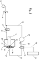
- FIG. 2 a circuit diagram of the system according to the invention for cleaning the filter elements 5 is shown, wherein the cleaning tube 9 is shown only in one end portion.
- the cleaning tube 9 is closed at the end via a diaphragm valve 20.
- the diaphragm valve 20 comprises a valve body 21 which can be pressed against the cleaning tube 9 on the front side in order to close it.
- the valve body 21 is annularly surrounded by an elastic membrane 23, which is arranged in the region of a recess 22 on the pressure vessel 13.
- the membrane 23 is fixed to the pressure vessel 13 via a cover 30.
- the cover 30 comprises a connection 31, which connects via a line 32 a control space, which is formed between the membrane 23 and the cover 30, with a 3-2-way valve 33.
- the 3-2-way valve may connect the line 32 with a vent line 35, so that in the control chamber, the pressure drops and the diaphragm valve 20 lifts with the valve body 21 from the end of the cleaning tube 9.
- the opening of the cleaning pipe 9 is opened to the pressure chamber 13 and a cleaning gas arranged in the pressure chamber 13 can flow into the cleaning pipe 9.
- the 3-2-way valve 33 is connected to a further line 36 to an additional memory 37 which is fed via a line 38 from the compressor 14. If now the connection of the line 32 to the vent line 35 is closed via the filter control 15, which is connected to a control line 34 to the 3-2-way valve 33, the connection opens from the additional memory 37 via the line 36 and 32 to the control room at port 31. Thereby, the diaphragm valve 20 by lifting the pressure in the control chamber moved back to the closed position, and the valve body 21 is pressed against the end of the cleaning tube 9.
- the compressor 14 is connected via a line 39 to the pressure vessel 13, and can supply both the pressure vessel 13 and the auxiliary reservoir 37 with a pressurized gas. Both in the line 38 to the additional memory 37 and in the line 39, a valve 40 or 41 is arranged to shut off the line.
- the operation of the system for cleaning the filter elements 5 can be done so that both in the pressure vessel 13 and in the additional memory 37, a substantially constant cleaning pressure between 2.5 bar and 3.5 bar is generated, for example, about 2.8 bar. If a cleaning process is now triggered, a cleaning gas first flows out of the control chamber between the cover 30 and the membrane 20 via the vent line 35 to the outside in order to open the membrane valve 20. Then, the cleaning gas flows from the pressure vessel 13 into the cleaning pipe 9, wherein the flow cross sections and the pressure ratios are dimensioned so that the flow takes place in the subcritical region.
- the diaphragm valve 20 can now be closed by closing the 3-2-way valve 33 again, in which case via the additional memory 37, the line 32 and the control chamber adjacent to the diaphragm valve 20 are pressurized.
- the opening and closing of the diaphragm valve 20 can take place in a very short period of, for example, less than 0.2 s, in particular less than 0.15 s, so that the flow losses are kept low.
- FIG. 2 is the pneumatic circuit diagram of the system only shown schematically.
- the 3-way valve 33 may be disposed directly on the cover 30 to minimize the volume of the conduit 32 and to ensure a fast response time of the diaphragm valve 20.
- other valves and control lines may be provided to the function of the system to ensure.
- the controller 15 can detect the pressure in all lines.
- FIG. 3 is a pressure-time diagram of a cleaning process shown.
- the diaphragm valve is opened so that the pressure in the cleaning tube 9 briefly increases from 0 bar (ambient pressure) to 2 bar.
- the cleaning gas flows from the pressure vessel 13 into the cleaning pipe 9, so that the pressure in the pressure vessel 13 is reduced, from initially 2.8 bar to about 2 bar.
- the pressure amplitude during a cleaning process can be in a range between 0.5 bar to 2.5 bar.
- the diaphragm valve 20 is closed suddenly, and in the cleaning tube 9 is again the initial pressure of 0 bar (ambient pressure).
- the pressure vessel 13 now has to be refilled again from 2 bar to 2.8 bar via the compressor 14.
- some cleaning gas must be introduced into the additional storage 37, so that the discharged during the venting cleaning gas is refilled.
- the cleaning gas after cleaning must first be generated only against the residual pressure in the pressure vessel 13 and are generated until reaching the cleaning pressure in each case only against the pressure currently present in the pressure vessel 13, whereby considerable electrical energy is saved.
- the energy consumption of the compressor 13 is highly dependent on the back pressure or pressure ratio.
- the necessary cleaning pressure is varied by the filter control and adapted to the operating conditions of the filter system.
- FIG. 4 shows a pressure-time diagram over a cleaning cycle with a total too long opening time.
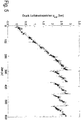
- FIG. 5 is an example of a pressure-time diagram of the pressure vessel shown at the beginning of several cleaning cycles.
- the generation of compressed air during the first filling process takes about 295 s.
- the pre-pressure in the compressed air reservoir drops by approx. 0.85 bar to 1.95 bar.
- the production of the pressure consumed per cleaning takes about 75 s.
- the minimum pause time between two cleaning operations is determined.
- the filter system can detect the degree of soiling or blockage on the filter elements 5 by means of differential pressure measurement.
- the controller may determine the length of pause time between each purging operation, for example by controlling the power of the compressor. The minimum time between two cleaning operations is therefore equal to the time required for the compressor 13 to increase the pressure of the cleaning gas to the desired cleaning pressure.
- the compressor 13 may then be operated at a constant speed for a particular level of soiling.
- the maximum pressure in the compressed air reservoir can also be controlled via the controller.
Landscapes
- Chemical & Material Sciences (AREA)
- Chemical Kinetics & Catalysis (AREA)
- Filtering Of Dispersed Particles In Gases (AREA)
Claims (9)
- Installation pour le nettoyage de filtres (1), en particulier fait de matériaux filtrants textiles, avec un compresseur (14) par lequel un gaz de nettoyage peut être comprimé jusqu'à une pression de nettoyage et amené dans un réservoir sous pression (13), le réservoir sous pression (13) étant raccordé à un tuyau de nettoyage (9) au moyen duquel le gaz de nettoyage peut être injecté dans un filtre (5) via des ouvertures de buse (10), caractérisée en ce qu'il est prévu, pour fermer le tuyau de nettoyage (9) raccordé au réservoir sous pression (13), une vanne à membrane (20) fonctionnant principalement dans la plage sous-critique par rapport à la pression de nettoyage du compresseur (14), le compresseur (14) pouvant créer dans le réservoir sous pression (13) une pression de nettoyage comprise entre 2 bars et 4 bars et la pression dans le réservoir sous pression (13) baissant de 0,5 bar à 2,5 bars pendant une opération de nettoyage et étant relevée par le compresseur (14) après l'opération de nettoyage jusqu'à la pression de nettoyage initiale et l'ouverture et la fermeture de la vanne à membrane (20) s'effectuant en moins de 0,2 s, la vanne à membrane (20) étant reliée par une conduite (32, 36), du côté opposé au réservoir sous pression (13), à un accumulateur supplémentaire (37) sous pression et la pression dans l'accumulateur supplémentaire (37) étant maintenue par le compresseur (14) sensiblement à la pression de nettoyage, et la vanne à membrane (20) étant raccordée, du côté opposé au réservoir sous pression (13), à une conduite pouvant être purgée de son air (32), la conduite pouvant être purgée de son air (32) comportant une vanne à 3-2 voies (33) et la vanne à 3-2 voies (33) étant reliée par un premier raccord à un réservoir sensiblement non pressurisé ou à une sortie et par un deuxième raccord à l'accumulateur supplémentaire (37).
- Installation selon la revendication 1, caractérisée en ce que la pression dans le réservoir sous pression (13) peut être contrôlée par une commande en fonction de la pression de nettoyage nécessaire au niveau du tuyau de nettoyage (9).
- Installation selon la revendication 2, caractérisée en ce que le degré d'encrassement du filtre (5) peut être déterminé par une mesure de la différence de pression et la longueur des intervalles de nettoyage peut être contrôlée en fonction du degré de colmatage.
- Installation selon l'une des revendications précédentes, caractérisée en ce que la puissance du compresseur (14) peut être contrôlée en fonction de la longueur des intervalles de nettoyage.
- Installation selon l'une des revendications précédentes, caractérisée en ce que le compresseur (14) crée une pression de nettoyage comprise entre 2,5 bars et 3,5 bars dans le réservoir sous pression (13).
- Installation selon l'une des revendications précédentes, caractérisée en ce que le tuyau de nettoyage (9) présente une section d'écoulement sensiblement constante, qui est plus grande que l'aire de toutes les ouvertures de buse (10) du tuyau de nettoyage (9).
- Procédé pour faire fonctionner une installation de nettoyage de filtres (1) selon l'une des revendications précédentes, avec un compresseur (14) par lequel un gaz de nettoyage peut être comprimé jusqu'à une pression de nettoyage et amené dans un réservoir sous pression (13), le réservoir sous pression (13) étant raccordé à un tuyau de nettoyage (9) au moyen duquel le gaz de nettoyage peut être injecté dans un filtre (5) via des ouvertures de buse (10) pour une opération de nettoyage, une vanne à membrane (20) pouvant être actionnée par une commande étant prévue pour fermer le tuyau de nettoyage (9) raccordé au réservoir sous pression (13), caractérisé en ce que le compresseur (14) est commandé par la commande de telle façon que lors de l'ouverture de la vanne à membrane (20), il se crée des écoulements principalement sous-critiques par rapport à la pression de nettoyage dans le réservoir sous pression (13) et à la pression dans le tuyau de nettoyage (9), le compresseur (14) créant dans le réservoir sous pression (13) une pression de nettoyage comprise entre 2 bars et 4 bars et la pression baissant de 0,5 bar à 2,5 bars dans le réservoir sous pression (13) lors d'une opération de nettoyage et étant augmentée par le compresseur (14) après l'opération de nettoyage jusqu'à la pression de nettoyage initiale et l'ouverture et la fermeture de la vanne à membrane (20) s'effectuant en moins de 0,2 s.
- Procédé selon la revendication 7, caractérisé en ce que le compresseur (14) est contrôlé par la commande de telle façon que le gaz de nettoyage ne soit comprimé que dans la quantité nécessaire pour le nettoyage suivant et sous la pression nécessaire pour celui-ci.
- Procédé selon la revendication 7 ou 8, caractérisé en ce que le compresseur (14) est contrôlé par la commande de telle façon et la puissance du compresseur (14) est régulée en fonction du degré d'encrassement.
Applications Claiming Priority (1)
| Application Number | Priority Date | Filing Date | Title |
|---|---|---|---|
| DE102011056062A DE102011056062A1 (de) | 2011-12-05 | 2011-12-05 | Anlage zum Reinigen von Filtern und Verfahren zum Betreiben einer Anlage zum Reinigen von Filtern |
Publications (2)
| Publication Number | Publication Date |
|---|---|
| EP2602016A1 EP2602016A1 (fr) | 2013-06-12 |
| EP2602016B1 true EP2602016B1 (fr) | 2017-06-21 |
Family
ID=47227633
Family Applications (1)
| Application Number | Title | Priority Date | Filing Date |
|---|---|---|---|
| EP12193504.3A Active EP2602016B1 (fr) | 2011-12-05 | 2012-11-21 | Installation de nettoyage de filtres et procédé d'actionnement d'une installation de nettoyage de filtres |
Country Status (2)
| Country | Link |
|---|---|
| EP (1) | EP2602016B1 (fr) |
| DE (1) | DE102011056062A1 (fr) |
Families Citing this family (8)
| Publication number | Priority date | Publication date | Assignee | Title |
|---|---|---|---|---|
| US8894744B2 (en) | 2012-03-29 | 2014-11-25 | Alstom Technology Ltd | System and method of cleaning particulate collection devices used in a flue gas processing system |
| DE102013113334A1 (de) * | 2013-12-02 | 2015-06-03 | Jochen Deichmann | Vorrichtung zum Reinigen von Gasen |
| US9782711B2 (en) | 2014-01-21 | 2017-10-10 | Covanta Energy, Llc | System and method for automatic control of differential pressure in a baghouse system |
| EP2913091B1 (fr) | 2014-02-26 | 2018-07-18 | General Electric Technology GmbH | Procédé de nettoyage d'un système de filter en tissu |
| EP3212306B1 (fr) | 2014-10-28 | 2021-04-07 | Boehringer Ingelheim Pharma GmbH & Co. KG | Procédé de nettoyage et dispositif de commande |
| US20160367929A1 (en) * | 2015-06-17 | 2016-12-22 | Alstom Technology Ltd | Fabric filter and method for cleaning a fabric filter |
| DE102018121134A1 (de) | 2018-08-29 | 2020-03-05 | DFT GmbH Deichmann Filter Technik | Verfahren zum Reinigen von Filtern |
| EP4149652B1 (fr) | 2020-05-15 | 2025-08-06 | Donaldson Company, Inc. | Systèmes de filtration avec commande sélective d'impulsion |
Citations (1)
| Publication number | Priority date | Publication date | Assignee | Title |
|---|---|---|---|---|
| US6270732B1 (en) * | 1998-06-30 | 2001-08-07 | Nanogram Corporation | Particle collection apparatus and associated methods |
Family Cites Families (6)
| Publication number | Priority date | Publication date | Assignee | Title |
|---|---|---|---|---|
| NL250037A (fr) * | 1959-04-01 | 1900-01-01 | ||
| US4465497A (en) * | 1980-05-02 | 1984-08-14 | Howeth David F | Pneumatic cyclic event timing actuator and control circuit for use with air blast filter cleaning and bulk material bin blasting systems |
| US4690166A (en) * | 1985-07-19 | 1987-09-01 | Howeth David Franklin | Pressure dependent dust control filter compressed air reversed flushing control system |
| DE3939645C3 (de) | 1989-11-30 | 1996-03-21 | Gore W L & Ass Gmbh | Staubabscheider mit schlauchförmigen Filterelementen und Verfahren zum Wechseln derselben |
| DE9103538U1 (de) | 1991-03-22 | 1991-06-27 | P & S Filtration GmbH, 3320 Salzgitter | Textiles Filterelement |
| ITMI20012237A1 (it) * | 2001-10-25 | 2003-04-25 | Aurelio Messina | Procedimento e dispositivo di lavaggio per filtri depolveratori |
-
2011
- 2011-12-05 DE DE102011056062A patent/DE102011056062A1/de not_active Ceased
-
2012
- 2012-11-21 EP EP12193504.3A patent/EP2602016B1/fr active Active
Patent Citations (1)
| Publication number | Priority date | Publication date | Assignee | Title |
|---|---|---|---|---|
| US6270732B1 (en) * | 1998-06-30 | 2001-08-07 | Nanogram Corporation | Particle collection apparatus and associated methods |
Also Published As
| Publication number | Publication date |
|---|---|
| EP2602016A1 (fr) | 2013-06-12 |
| DE102011056062A1 (de) | 2013-06-06 |
Similar Documents
| Publication | Publication Date | Title |
|---|---|---|
| EP2602016B1 (fr) | Installation de nettoyage de filtres et procédé d'actionnement d'une installation de nettoyage de filtres | |
| EP3212306B1 (fr) | Procédé de nettoyage et dispositif de commande | |
| DE2748079A1 (de) | Wasserdruck-verstaerkungssystem und steuerventil sowie steuerverfahren | |
| DE19701983C1 (de) | Ringspaltinjektor | |
| DE1295348B (de) | Spritzrohr fuer Papiermaschinen | |
| DE2351613A1 (de) | Staubfiltereinrichtung | |
| DE10257910B3 (de) | Verfahren zur Überwachung einer Rohrleitung sowie Stellungsregler für ein Regelventil | |
| DE3323324C3 (de) | Verfahren und Vorrichtung zum Steuern eines Rohrtrenners in Abhängigkeit einer an einer Vergleichsstelle vorgegebenen Druckdifferenz | |
| DE102022104857A1 (de) | Einrichtung und Verfahren zur Rückspülung eines Filters sowie System zur Filterung | |
| DE102011056521A1 (de) | Ventilvorrichtung | |
| EP3052214B1 (fr) | Installation de filtration dotée d'un nettoyage à régulation automatique | |
| DE102013211536A1 (de) | Pulverfördervorrichtung insbesondere für Beschichtungspulver und Verfahren zum Betreiben einer Pulverfördervorrichtung | |
| EP1649918B1 (fr) | Dispositif de nettoyage de filtres de dépoussiérage | |
| WO2019081216A1 (fr) | Procédé de suppression d'eau produite d'une pile à combustible | |
| EP3650098A2 (fr) | Procédé de remplissage de filtres à plaque | |
| EP3623032B1 (fr) | Système de filtrage à injection directe d'air de nettoyage ainsi que procédé de nettoyage | |
| WO2023208440A1 (fr) | Procédé de fonctionnement d'un système de réservoir de fluide, et système de réservoir de fluide pouvant fonctionner à l'aide d'un tel procédé | |
| EP3600767B1 (fr) | Installation et procédé de découpe par jet d'eau chargée d'abrasif en suspension | |
| DE102022105565A1 (de) | Pneumatisch gesteuerte Ventileinheit, Ventilanlage und Verfahren zum Betreiben einer Ventileinheit | |
| DE69917585T2 (de) | Ventil zur Regelung eines Druckgases | |
| AT511731B1 (de) | Kavitationsoptimierte drosselbohrungen | |
| EP3616772A1 (fr) | Procédé de nettoyage de filtres | |
| EP2716208A1 (fr) | Dispositif de nettoyage de canaux, tuyaux, conduites étroits ou analogues | |
| EP3011209A1 (fr) | Ferrure de tuyau d'aspiration | |
| WO2000003786A2 (fr) | Injecteur a fente annulaire |
Legal Events
| Date | Code | Title | Description |
|---|---|---|---|
| PUAI | Public reference made under article 153(3) epc to a published international application that has entered the european phase |
Free format text: ORIGINAL CODE: 0009012 |
|
| AK | Designated contracting states |
Kind code of ref document: A1 Designated state(s): AL AT BE BG CH CY CZ DE DK EE ES FI FR GB GR HR HU IE IS IT LI LT LU LV MC MK MT NL NO PL PT RO RS SE SI SK SM TR |
|
| AX | Request for extension of the european patent |
Extension state: BA ME |
|
| 17P | Request for examination filed |
Effective date: 20131210 |
|
| RBV | Designated contracting states (corrected) |
Designated state(s): AL AT BE BG CH CY CZ DE DK EE ES FI FR GB GR HR HU IE IS IT LI LT LU LV MC MK MT NL NO PL PT RO RS SE SI SK SM TR |
|
| 17Q | First examination report despatched |
Effective date: 20150717 |
|
| GRAP | Despatch of communication of intention to grant a patent |
Free format text: ORIGINAL CODE: EPIDOSNIGR1 |
|
| INTG | Intention to grant announced |
Effective date: 20170323 |
|
| GRAS | Grant fee paid |
Free format text: ORIGINAL CODE: EPIDOSNIGR3 |
|
| GRAA | (expected) grant |
Free format text: ORIGINAL CODE: 0009210 |
|
| AK | Designated contracting states |
Kind code of ref document: B1 Designated state(s): AL AT BE BG CH CY CZ DE DK EE ES FI FR GB GR HR HU IE IS IT LI LT LU LV MC MK MT NL NO PL PT RO RS SE SI SK SM TR |
|
| REG | Reference to a national code |
Ref country code: GB Ref legal event code: FG4D Free format text: NOT ENGLISH |
|
| REG | Reference to a national code |
Ref country code: CH Ref legal event code: EP |
|
| REG | Reference to a national code |
Ref country code: IE Ref legal event code: FG4D Free format text: LANGUAGE OF EP DOCUMENT: GERMAN |
|
| REG | Reference to a national code |
Ref country code: AT Ref legal event code: REF Ref document number: 902413 Country of ref document: AT Kind code of ref document: T Effective date: 20170715 |
|
| REG | Reference to a national code |
Ref country code: DE Ref legal event code: R096 Ref document number: 502012010581 Country of ref document: DE |
|
| REG | Reference to a national code |
Ref country code: NL Ref legal event code: MP Effective date: 20170621 |
|
| PG25 | Lapsed in a contracting state [announced via postgrant information from national office to epo] |
Ref country code: LT Free format text: LAPSE BECAUSE OF FAILURE TO SUBMIT A TRANSLATION OF THE DESCRIPTION OR TO PAY THE FEE WITHIN THE PRESCRIBED TIME-LIMIT Effective date: 20170621 Ref country code: FI Free format text: LAPSE BECAUSE OF FAILURE TO SUBMIT A TRANSLATION OF THE DESCRIPTION OR TO PAY THE FEE WITHIN THE PRESCRIBED TIME-LIMIT Effective date: 20170621 Ref country code: HR Free format text: LAPSE BECAUSE OF FAILURE TO SUBMIT A TRANSLATION OF THE DESCRIPTION OR TO PAY THE FEE WITHIN THE PRESCRIBED TIME-LIMIT Effective date: 20170621 Ref country code: NO Free format text: LAPSE BECAUSE OF FAILURE TO SUBMIT A TRANSLATION OF THE DESCRIPTION OR TO PAY THE FEE WITHIN THE PRESCRIBED TIME-LIMIT Effective date: 20170921 Ref country code: GR Free format text: LAPSE BECAUSE OF FAILURE TO SUBMIT A TRANSLATION OF THE DESCRIPTION OR TO PAY THE FEE WITHIN THE PRESCRIBED TIME-LIMIT Effective date: 20170922 |
|
| REG | Reference to a national code |
Ref country code: LT Ref legal event code: MG4D |
|
| REG | Reference to a national code |
Ref country code: FR Ref legal event code: PLFP Year of fee payment: 6 |
|
| PG25 | Lapsed in a contracting state [announced via postgrant information from national office to epo] |
Ref country code: LV Free format text: LAPSE BECAUSE OF FAILURE TO SUBMIT A TRANSLATION OF THE DESCRIPTION OR TO PAY THE FEE WITHIN THE PRESCRIBED TIME-LIMIT Effective date: 20170621 Ref country code: BG Free format text: LAPSE BECAUSE OF FAILURE TO SUBMIT A TRANSLATION OF THE DESCRIPTION OR TO PAY THE FEE WITHIN THE PRESCRIBED TIME-LIMIT Effective date: 20170921 Ref country code: NL Free format text: LAPSE BECAUSE OF FAILURE TO SUBMIT A TRANSLATION OF THE DESCRIPTION OR TO PAY THE FEE WITHIN THE PRESCRIBED TIME-LIMIT Effective date: 20170621 Ref country code: RS Free format text: LAPSE BECAUSE OF FAILURE TO SUBMIT A TRANSLATION OF THE DESCRIPTION OR TO PAY THE FEE WITHIN THE PRESCRIBED TIME-LIMIT Effective date: 20170621 Ref country code: SE Free format text: LAPSE BECAUSE OF FAILURE TO SUBMIT A TRANSLATION OF THE DESCRIPTION OR TO PAY THE FEE WITHIN THE PRESCRIBED TIME-LIMIT Effective date: 20170621 |
|
| PG25 | Lapsed in a contracting state [announced via postgrant information from national office to epo] |
Ref country code: EE Free format text: LAPSE BECAUSE OF FAILURE TO SUBMIT A TRANSLATION OF THE DESCRIPTION OR TO PAY THE FEE WITHIN THE PRESCRIBED TIME-LIMIT Effective date: 20170621 Ref country code: CZ Free format text: LAPSE BECAUSE OF FAILURE TO SUBMIT A TRANSLATION OF THE DESCRIPTION OR TO PAY THE FEE WITHIN THE PRESCRIBED TIME-LIMIT Effective date: 20170621 Ref country code: RO Free format text: LAPSE BECAUSE OF FAILURE TO SUBMIT A TRANSLATION OF THE DESCRIPTION OR TO PAY THE FEE WITHIN THE PRESCRIBED TIME-LIMIT Effective date: 20170621 Ref country code: SK Free format text: LAPSE BECAUSE OF FAILURE TO SUBMIT A TRANSLATION OF THE DESCRIPTION OR TO PAY THE FEE WITHIN THE PRESCRIBED TIME-LIMIT Effective date: 20170621 |
|
| PG25 | Lapsed in a contracting state [announced via postgrant information from national office to epo] |
Ref country code: SM Free format text: LAPSE BECAUSE OF FAILURE TO SUBMIT A TRANSLATION OF THE DESCRIPTION OR TO PAY THE FEE WITHIN THE PRESCRIBED TIME-LIMIT Effective date: 20170621 Ref country code: IS Free format text: LAPSE BECAUSE OF FAILURE TO SUBMIT A TRANSLATION OF THE DESCRIPTION OR TO PAY THE FEE WITHIN THE PRESCRIBED TIME-LIMIT Effective date: 20171021 Ref country code: PL Free format text: LAPSE BECAUSE OF FAILURE TO SUBMIT A TRANSLATION OF THE DESCRIPTION OR TO PAY THE FEE WITHIN THE PRESCRIBED TIME-LIMIT Effective date: 20170621 Ref country code: ES Free format text: LAPSE BECAUSE OF FAILURE TO SUBMIT A TRANSLATION OF THE DESCRIPTION OR TO PAY THE FEE WITHIN THE PRESCRIBED TIME-LIMIT Effective date: 20170621 Ref country code: IT Free format text: LAPSE BECAUSE OF FAILURE TO SUBMIT A TRANSLATION OF THE DESCRIPTION OR TO PAY THE FEE WITHIN THE PRESCRIBED TIME-LIMIT Effective date: 20170621 |
|
| REG | Reference to a national code |
Ref country code: DE Ref legal event code: R097 Ref document number: 502012010581 Country of ref document: DE |
|
| PLBE | No opposition filed within time limit |
Free format text: ORIGINAL CODE: 0009261 |
|
| STAA | Information on the status of an ep patent application or granted ep patent |
Free format text: STATUS: NO OPPOSITION FILED WITHIN TIME LIMIT |
|
| PG25 | Lapsed in a contracting state [announced via postgrant information from national office to epo] |
Ref country code: DK Free format text: LAPSE BECAUSE OF FAILURE TO SUBMIT A TRANSLATION OF THE DESCRIPTION OR TO PAY THE FEE WITHIN THE PRESCRIBED TIME-LIMIT Effective date: 20170621 |
|
| 26N | No opposition filed |
Effective date: 20180322 |
|
| PG25 | Lapsed in a contracting state [announced via postgrant information from national office to epo] |
Ref country code: MC Free format text: LAPSE BECAUSE OF FAILURE TO SUBMIT A TRANSLATION OF THE DESCRIPTION OR TO PAY THE FEE WITHIN THE PRESCRIBED TIME-LIMIT Effective date: 20170621 |
|
| GBPC | Gb: european patent ceased through non-payment of renewal fee |
Effective date: 20171121 |
|
| PG25 | Lapsed in a contracting state [announced via postgrant information from national office to epo] |
Ref country code: LI Free format text: LAPSE BECAUSE OF NON-PAYMENT OF DUE FEES Effective date: 20171130 Ref country code: CH Free format text: LAPSE BECAUSE OF NON-PAYMENT OF DUE FEES Effective date: 20171130 |
|
| PG25 | Lapsed in a contracting state [announced via postgrant information from national office to epo] |
Ref country code: LU Free format text: LAPSE BECAUSE OF NON-PAYMENT OF DUE FEES Effective date: 20171121 Ref country code: SI Free format text: LAPSE BECAUSE OF FAILURE TO SUBMIT A TRANSLATION OF THE DESCRIPTION OR TO PAY THE FEE WITHIN THE PRESCRIBED TIME-LIMIT Effective date: 20170621 |
|
| REG | Reference to a national code |
Ref country code: BE Ref legal event code: MM Effective date: 20171130 |
|
| REG | Reference to a national code |
Ref country code: IE Ref legal event code: MM4A |
|
| PG25 | Lapsed in a contracting state [announced via postgrant information from national office to epo] |
Ref country code: MT Free format text: LAPSE BECAUSE OF FAILURE TO SUBMIT A TRANSLATION OF THE DESCRIPTION OR TO PAY THE FEE WITHIN THE PRESCRIBED TIME-LIMIT Effective date: 20170621 |
|
| PG25 | Lapsed in a contracting state [announced via postgrant information from national office to epo] |
Ref country code: IE Free format text: LAPSE BECAUSE OF NON-PAYMENT OF DUE FEES Effective date: 20171121 |
|
| PG25 | Lapsed in a contracting state [announced via postgrant information from national office to epo] |
Ref country code: GB Free format text: LAPSE BECAUSE OF NON-PAYMENT OF DUE FEES Effective date: 20171121 Ref country code: BE Free format text: LAPSE BECAUSE OF NON-PAYMENT OF DUE FEES Effective date: 20171130 |
|
| PG25 | Lapsed in a contracting state [announced via postgrant information from national office to epo] |
Ref country code: HU Free format text: LAPSE BECAUSE OF FAILURE TO SUBMIT A TRANSLATION OF THE DESCRIPTION OR TO PAY THE FEE WITHIN THE PRESCRIBED TIME-LIMIT; INVALID AB INITIO Effective date: 20121121 |
|
| PG25 | Lapsed in a contracting state [announced via postgrant information from national office to epo] |
Ref country code: CY Free format text: LAPSE BECAUSE OF NON-PAYMENT OF DUE FEES Effective date: 20170621 |
|
| PG25 | Lapsed in a contracting state [announced via postgrant information from national office to epo] |
Ref country code: MK Free format text: LAPSE BECAUSE OF FAILURE TO SUBMIT A TRANSLATION OF THE DESCRIPTION OR TO PAY THE FEE WITHIN THE PRESCRIBED TIME-LIMIT Effective date: 20170621 |
|
| PG25 | Lapsed in a contracting state [announced via postgrant information from national office to epo] |
Ref country code: TR Free format text: LAPSE BECAUSE OF FAILURE TO SUBMIT A TRANSLATION OF THE DESCRIPTION OR TO PAY THE FEE WITHIN THE PRESCRIBED TIME-LIMIT Effective date: 20170621 |
|
| PG25 | Lapsed in a contracting state [announced via postgrant information from national office to epo] |
Ref country code: PT Free format text: LAPSE BECAUSE OF FAILURE TO SUBMIT A TRANSLATION OF THE DESCRIPTION OR TO PAY THE FEE WITHIN THE PRESCRIBED TIME-LIMIT Effective date: 20170621 |
|
| PG25 | Lapsed in a contracting state [announced via postgrant information from national office to epo] |
Ref country code: AL Free format text: LAPSE BECAUSE OF FAILURE TO SUBMIT A TRANSLATION OF THE DESCRIPTION OR TO PAY THE FEE WITHIN THE PRESCRIBED TIME-LIMIT Effective date: 20170621 |
|
| PGFP | Annual fee paid to national office [announced via postgrant information from national office to epo] |
Ref country code: DE Payment date: 20251010 Year of fee payment: 14 |
|
| PGFP | Annual fee paid to national office [announced via postgrant information from national office to epo] |
Ref country code: AT Payment date: 20251104 Year of fee payment: 14 |
|
| PGFP | Annual fee paid to national office [announced via postgrant information from national office to epo] |
Ref country code: FR Payment date: 20251031 Year of fee payment: 14 |