EP2601372B1 - Window for an object - Google Patents
Window for an object Download PDFInfo
- Publication number
- EP2601372B1 EP2601372B1 EP11746663.1A EP11746663A EP2601372B1 EP 2601372 B1 EP2601372 B1 EP 2601372B1 EP 11746663 A EP11746663 A EP 11746663A EP 2601372 B1 EP2601372 B1 EP 2601372B1
- Authority
- EP
- European Patent Office
- Prior art keywords
- window
- signal
- light
- photoluminescent material
- sun blind
- Prior art date
- Legal status (The legal status is an assumption and is not a legal conclusion. Google has not performed a legal analysis and makes no representation as to the accuracy of the status listed.)
- Not-in-force
Links
- 239000000463 material Substances 0.000 claims description 139
- 238000000034 method Methods 0.000 claims description 13
- 238000004590 computer program Methods 0.000 claims description 9
- 241000446313 Lamella Species 0.000 description 17
- 239000011521 glass Substances 0.000 description 11
- 239000003086 colorant Substances 0.000 description 4
- 230000007613 environmental effect Effects 0.000 description 4
- 239000000049 pigment Substances 0.000 description 4
- 239000011248 coating agent Substances 0.000 description 3
- 238000000576 coating method Methods 0.000 description 3
- 230000001419 dependent effect Effects 0.000 description 3
- 238000005286 illumination Methods 0.000 description 3
- 230000007935 neutral effect Effects 0.000 description 3
- 231100000252 nontoxic Toxicity 0.000 description 3
- 230000003000 nontoxic effect Effects 0.000 description 3
- 230000005855 radiation Effects 0.000 description 3
- 230000002285 radioactive effect Effects 0.000 description 3
- 239000000758 substrate Substances 0.000 description 3
- 230000000475 sunscreen effect Effects 0.000 description 3
- 239000000516 sunscreening agent Substances 0.000 description 3
- YZCKVEUIGOORGS-NJFSPNSNSA-N Tritium Chemical compound [3H] YZCKVEUIGOORGS-NJFSPNSNSA-N 0.000 description 2
- XAUTYMZTJWXZHZ-IGUOPLJTSA-K bismuth;(e)-1-n'-[2-[[5-[(dimethylamino)methyl]furan-2-yl]methylsulfanyl]ethyl]-1-n-methyl-2-nitroethene-1,1-diamine;2-hydroxypropane-1,2,3-tricarboxylate Chemical compound [Bi+3].[O-]C(=O)CC(O)(CC([O-])=O)C([O-])=O.[O-][N+](=O)\C=C(/NC)NCCSCC1=CC=C(CN(C)C)O1 XAUTYMZTJWXZHZ-IGUOPLJTSA-K 0.000 description 2
- 230000000694 effects Effects 0.000 description 2
- 239000007850 fluorescent dye Substances 0.000 description 2
- 238000005259 measurement Methods 0.000 description 2
- 230000007246 mechanism Effects 0.000 description 2
- 230000003287 optical effect Effects 0.000 description 2
- 230000007704 transition Effects 0.000 description 2
- 229910052722 tritium Inorganic materials 0.000 description 2
- 239000005084 Strontium aluminate Substances 0.000 description 1
- 239000005083 Zinc sulfide Substances 0.000 description 1
- 230000002411 adverse Effects 0.000 description 1
- 230000008901 benefit Effects 0.000 description 1
- 239000013590 bulk material Substances 0.000 description 1
- 238000005034 decoration Methods 0.000 description 1
- 238000001514 detection method Methods 0.000 description 1
- 238000005265 energy consumption Methods 0.000 description 1
- 230000003203 everyday effect Effects 0.000 description 1
- 230000036541 health Effects 0.000 description 1
- 230000003993 interaction Effects 0.000 description 1
- 238000002955 isolation Methods 0.000 description 1
- 230000008569 process Effects 0.000 description 1
- 230000005610 quantum mechanics Effects 0.000 description 1
- 229910052705 radium Inorganic materials 0.000 description 1
- HCWPIIXVSYCSAN-UHFFFAOYSA-N radium atom Chemical compound [Ra] HCWPIIXVSYCSAN-UHFFFAOYSA-N 0.000 description 1
- 230000004044 response Effects 0.000 description 1
- 238000007789 sealing Methods 0.000 description 1
- FNWBQFMGIFLWII-UHFFFAOYSA-N strontium aluminate Chemical compound [O-2].[O-2].[O-2].[O-2].[O-2].[Al+3].[Al+3].[Sr+2].[Sr+2] FNWBQFMGIFLWII-UHFFFAOYSA-N 0.000 description 1
- 230000032258 transport Effects 0.000 description 1
- 229910052984 zinc sulfide Inorganic materials 0.000 description 1
- DRDVZXDWVBGGMH-UHFFFAOYSA-N zinc;sulfide Chemical compound [S-2].[Zn+2] DRDVZXDWVBGGMH-UHFFFAOYSA-N 0.000 description 1
Images
Classifications
-
- H—ELECTRICITY
- H05—ELECTRIC TECHNIQUES NOT OTHERWISE PROVIDED FOR
- H05B—ELECTRIC HEATING; ELECTRIC LIGHT SOURCES NOT OTHERWISE PROVIDED FOR; CIRCUIT ARRANGEMENTS FOR ELECTRIC LIGHT SOURCES, IN GENERAL
- H05B47/00—Circuit arrangements for operating light sources in general, i.e. where the type of light source is not relevant
- H05B47/10—Controlling the light source
-
- E—FIXED CONSTRUCTIONS
- E06—DOORS, WINDOWS, SHUTTERS, OR ROLLER BLINDS IN GENERAL; LADDERS
- E06B—FIXED OR MOVABLE CLOSURES FOR OPENINGS IN BUILDINGS, VEHICLES, FENCES OR LIKE ENCLOSURES IN GENERAL, e.g. DOORS, WINDOWS, BLINDS, GATES
- E06B9/00—Screening or protective devices for wall or similar openings, with or without operating or securing mechanisms; Closures of similar construction
- E06B9/24—Screens or other constructions affording protection against light, especially against sunshine; Similar screens for privacy or appearance; Slat blinds
- E06B2009/247—Electrically powered illumination
-
- E—FIXED CONSTRUCTIONS
- E06—DOORS, WINDOWS, SHUTTERS, OR ROLLER BLINDS IN GENERAL; LADDERS
- E06B—FIXED OR MOVABLE CLOSURES FOR OPENINGS IN BUILDINGS, VEHICLES, FENCES OR LIKE ENCLOSURES IN GENERAL, e.g. DOORS, WINDOWS, BLINDS, GATES
- E06B9/00—Screening or protective devices for wall or similar openings, with or without operating or securing mechanisms; Closures of similar construction
- E06B9/24—Screens or other constructions affording protection against light, especially against sunshine; Similar screens for privacy or appearance; Slat blinds
- E06B2009/2476—Solar cells
-
- Y—GENERAL TAGGING OF NEW TECHNOLOGICAL DEVELOPMENTS; GENERAL TAGGING OF CROSS-SECTIONAL TECHNOLOGIES SPANNING OVER SEVERAL SECTIONS OF THE IPC; TECHNICAL SUBJECTS COVERED BY FORMER USPC CROSS-REFERENCE ART COLLECTIONS [XRACs] AND DIGESTS
- Y02—TECHNOLOGIES OR APPLICATIONS FOR MITIGATION OR ADAPTATION AGAINST CLIMATE CHANGE
- Y02A—TECHNOLOGIES FOR ADAPTATION TO CLIMATE CHANGE
- Y02A30/00—Adapting or protecting infrastructure or their operation
- Y02A30/24—Structural elements or technologies for improving thermal insulation
-
- Y—GENERAL TAGGING OF NEW TECHNOLOGICAL DEVELOPMENTS; GENERAL TAGGING OF CROSS-SECTIONAL TECHNOLOGIES SPANNING OVER SEVERAL SECTIONS OF THE IPC; TECHNICAL SUBJECTS COVERED BY FORMER USPC CROSS-REFERENCE ART COLLECTIONS [XRACs] AND DIGESTS
- Y02—TECHNOLOGIES OR APPLICATIONS FOR MITIGATION OR ADAPTATION AGAINST CLIMATE CHANGE
- Y02B—CLIMATE CHANGE MITIGATION TECHNOLOGIES RELATED TO BUILDINGS, e.g. HOUSING, HOUSE APPLIANCES OR RELATED END-USER APPLICATIONS
- Y02B80/00—Architectural or constructional elements improving the thermal performance of buildings
Definitions
- the invention relates to a window for an object, an object comprising the window, a lighting system and a method for modifying the appearance of the object.
- DE 1174476 B discloses a dimming device comprising a drape located within a clear spacing sealed in air-tight fashion between two screens.
- the drape is adjustable by way of adjusting means, and at least one part of those adjusting means is located outside of the two screens and movable in response to magnetic actuation.
- WO 2008/135893 A1 discloses an illuminated window comprising a lighting device connected to a transparent pane and a daylight shielding device, for example a Venetian blind.
- the lighting device may particularly comprise OLEDs that typically cover the whole area of the pane.
- the daylight shielding device is optionally disposed between the first pane and an additional pane.
- US 6,601,634 B2 discloses a window cover apparatus that includes a window cover substrate and a mechanism for adjusting the configuration of the substrate relative to a window.
- Illuminating material such as phosphorescent material is provided on or in the substrate to provide illumination in darkness.
- the illuminating material may contain a color pigment and maybe configured to provide a colorful design in both daylight and darkness.
- DE3125620 discloses a three plate window in which bulk material of the central plate comprises a fluorescent compound, via TIR said central plate further transports as much as possible of converted light towards edge mounted photocells.
- the outer two plates respectively have a coating to protect the fluorescent compound against harmful ambient (UV-)radiation and a coating for color correction of the color shift caused by scattered light of the fluorescent coating.
- a window for an object which allows to generate light and which has an increased lifetime.
- a window for an object is presented, wherein the window comprises photoluminescent material located within the window as further defined in claim 1. Since the photoluminescent material is located within the window, the photoluminescent material is protected against environmental influences, in particular, against humidity, thereby increasing the lifetime of the photoluminescent material and, thus, of the window, which generates light by using the photoluminescent material.
- the photoluminescent material is sealingly located within the window. Since the photoluminescent material is sealingly located within the window, the degree of protection of the photoluminescent material against environmental influences is further increased, thereby further increasing the lifetime of the photoluminescent material.
- the window is preferentially a building window for being used in a building. It is further preferred that the window comprises at least two transparent plates defining a sealed space in which the photoluminescent material is located.
- the window comprises preferentially two or three glass plates defining at least one sealed space containing, for example, a vacuum or neutral gas.
- the sealed space is therefore preferentially used for sealing the photoluminescent material and for providing a temperature and/or noise protection of the inside of, for example, a building comprising the window.
- the photoluminescent material is a phosphorescent material.
- the phosphorescent material can be charged up during, for example, daylight, and the phosphorescent material can then emit phosphorescent light during, for example, darkness.
- the photoluminescent material is preferentially non-radioactive and non-toxic.
- the photoluminescent material is, for example, Super-LumiNova from the company RC TRITEC.
- a sun blind is integrated within the window, wherein the sun blind comprises the photoluminescent material.
- the sun blind with the photoluminescent material is preferentially located within the space defined between at least two transparent plates, which is preferentially sealed.
- the sun blind is preferentially covered with the photoluminescent material.
- the sun blind comprises a first side and a second side, wherein at least one of the first side and the second side comprises the photoluminescent material.
- first side is covered with a first photoluminescent material and the second side is covered with a second photoluminescent material being different to the first photoluminescent material.
- first and second photoluminescent materials can comprise different colors.
- the sun blind comprises several lamellae being covered with the photoluminescent material.
- the first side and the second side of the sun blind are formed by a first side and a second side of the lamellae. At least one of the sides of the lamellae can be covered by the photoluminescent material.
- the lamellae are preferentially rotatable by at least 180°.
- the window comprises at least one of a time providing unit, a light sensor, a presence sensor and a movement sensor for generating at least one of a time signal, a light signal, a presence signal and a movement signal, wherein the light signal is indicative of ambient light and/or light emitted by the photoluminescent material, the presence signal is indicative of a presence of an object within a predefined area and the movement signal is indicative of a movement of an object within a predefined area, wherein the sun blind is controllable based on at least one of the time signal, the light signal, the presence signal and the movement signal.
- a control of the sun blind based on the presence signal and/or based on the movement signal allows an interaction of the window with the ambience.
- the time providing unit is, for example, a clock for providing the time of the day or for providing the time which has lapsed since a starting time.
- the sun blind can be controlled such that the first side and the second side are shown at different times to the outside and/or the inside of a building comprising the window depending on the time signal, thereby allowing presenting a temporally changing pattern, in particular, a temporally changing color pattern.
- the light sensor can be adapted to sense the light outside of a building comprising the window for determining whether it is day or night, for instance, by determining whether the sensed light exceeds a predefined threshold or not.
- the sun blind can be controlled such that a side of the sun blind, in particular, sides of the lamellae, comprising the photoluminescent material is directed to the outside of the building, whereas during day the sun blind can be controlled such that the side comprising the photoluminescent material is directed to light inside or outside the building.
- the sun blind is controlled such that the side comprising the photoluminescent material is illuminated by daylight, in particular, uniformly illuminated by daylight.
- the light sensor can also be adapted to sense the light emitted by the photoluminescent material, wherein the sun blind can be controlled such that the side of the sun blind with the largest emitted light intensity is directed to a predefined direction, for example, to the outside or the inside of a building comprising the window.
- single lamellae are controllable depending on, for example, the time signal, the sensed light, the presence signal and/or the movement signal. If single lamellae are independently controllable, a large variety of patterns can be generated. The sun blind is preferentially also manually controllable.
- the photoluminescent material forms a pattern.
- the photoluminescent material can form letters, signs et cetera.
- the window comprises a light source for illuminating the photoluminescent material.
- the light source is preferentially a light emitting diode (LED).
- LEDs can be provided on lamellae of a sun blind for charging the photoluminescent material up, if the daylight is not sufficient and/or if a side of the sun blind comprising a photoluminescent material is directed to the inside of, for example, a building comprising the window.
- an object comprising a window as defined in claim 1 is presented.
- the object is preferentially a building comprising the window.
- a lighting system comprising:
- a method for modifying the appearance of an object comprising a window, wherein photoluminescent material is located within the window, wherein a sun blind is integrated within the window and wherein the sun blind comprises the photoluminescent material, wherein the method comprises:
- a computer program for modifying the appearance of an object comprises program code means for causing a lighting system as defined in claim 13 to carry out the steps of the method as defined in claim 14, when the computer program is run on a computer controlling the lighting system.
- window of claim 1 the object of claim 12, the lighting system of claim 13, the method of claim 14 and the computer program of claim 15 have similar and/or identical preferred embodiments, in particular, as defined in the dependent claims.
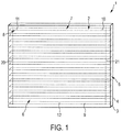
- Fig. 1 shows schematically and exemplarily a building window 1 comprising two transparent plates 3, 4 defining a sealed space 5 in which a sun blind 6 is located.
- the sun blind 6 comprises several lamellae 9 being covered with photoluminescent material 2.
- the sealed space 5 can contain a vacuum or neutral gas.
- the photoluminescent material 2 is a phosphorescent material being non-radioactive and non-toxic.
- a phosphorescent material does not immediately re-emit the radiation it absorbs.
- the slower time scales of the re-emission are associated with "forbidden" energy state transitions in quantum mechanics. As these transitions occur less often in certain materials, absorbed radiation may be re-emitted at a lower intensity for up to several hours.
- phosphorescence is a process in which energy absorbed by a phosphorescent material is released relatively slowly in the form of light. This is the mechanism used for "glow-in-the-dark" materials which are “charged” by exposure to light. While in general the phosphorescent material may contain radium or tritium which might be dangerous for health, in the present embodiment, as already mentioned above, a non-radioactive and non-toxic phosphorescent material is used like Super-LumiNova from the company RC TRITEC.
- the lamellae 9 comprise a first side 7 and a second side 8.
- the first side 7 is the upper side and the second side 8 is the lower side.
- the first sides 7 of the lamellae 9 form a first side of the overall sun blind 6, if the sun blind 6 is closed.
- the second sides 8 of the lamellae 9 form a second side of the sun blind 6, if the sun blind 6 is closed.
- the first sides 7 of the lamellae 9 form therefore a first side of the sun blind and the second sides 8 of the lamellae 9 form a second side of the sun blind 6.
- the phosphorescent material 2 is coated on the first sides 7 of the lamellae 9.
- both sides 7, 8 of the lamellae 9 can be coated with the phosphorescent material.
- the first side can be covered with a first phosphorescent material and the second side can be covered with a second phosphorescent material being different to the first phosphorescent material.
- the first and second phosphorescent materials can comprise different colors.
- the lamellae 9 are thin plastic rectangular shaped lamellae comprising the phosphorescent material 2.
- the lamellae 9 are connected together with threads 20, 21 in a known way, in order to allow the lamellae to be rotated over an angle of, for example, 180 °C and to be moved up and down for arranging the sun blind in a desired position.
- Light sensors 10, 11, 12 are arranged on some of the lamellae 9 for generating a light signal being indicative of ambient light and/or light emitted by the phosphorescent material 2, wherein the sun blind 6 is controllable based on the light signal.
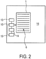
- Fig. 2 shows schematically and exemplarily the building window 1 with the sun blind 6 within a wall 16 of a building.
- a presence sensor 13 and a movement sensor 14 for generating a presence signal and a movement signal, respectively, are arranged.
- the presence signal is indicative of a presence of an object within a predefined area and the movement signal is indicative of a movement of an object within the predefined area.
- the predefined area is, for example, an area in front of the building or within an inner room of the building.
- the presence sensor and the movement sensor are, for example, based on a known infrared detection technique.
- a clock 19 is provided as a time providing unit for providing a time signal.
- a control unit 15 is provided for controlling the sun blind 6 depending on at least one of the light signal generated by the light sensors 10, 11, 12, the presence signal generated by the presence sensor 13, the movement signal generated by the movement sensor 14, and the time signal generated by the clock 19.
- the control unit 15 is adapted to control the angular position of the lamellae 9 depending on at least one of these signals.
- the control unit 15 can be adapted to control the sun blind 6 depending on the time such that, for example, the first side 7 and the second side 8 of the lamellae 9 are shown at predetermined times to the outside and/or the inside of the building, thereby allowing presenting a temporally changing pattern, in particular, a temporally changing color pattern.
- the light sensors 10, 11, 12 sense the light outside of the building for determining whether it is day or night, for instance, by determining whether the sensed light exceeds a predefined threshold or not.
- the threshold can be predefined by calibration measurements, wherein the intensity of the light is sensed, while it is know whether it is day or night.
- the control unit 15 can be adapted such that, during night, a side of the sun blind 6, in particular, the first sides 7 of the lamellae, which comprise the phosphorescent material 2, is directed to the outside of the building, whereas during the day the sun blind 6 can be controlled such that the side comprising the phosphorescent material is directed to light being inside or outside the building for charging up the phosphorescent material.
- control unit 15 is adapted such that during the day the first side 7 comprising the phosphorescent material 2 is substantially uniformly illuminated by daylight.
- the angular positions of the lamellae 9 can be controlled such that the first sides 7 are uniformly illuminated by the daylight.
- the angular positions of the lamella 9, which lead to a substantially uniform illumination by daylight, depend on, for example, the orientation of the building with respect to the sun, the position of the building window with respect to the building, the shape of the building, et cetera.
- the appropriate angular positions of the lamellae which ensure a substantially uniform illumination by daylight, can easily be determined by a user, for example, by try-and-error.
- the determined angular positions of the lamellae 9 can then be input into the control unit 15, in order to allow the control unit 15 to control the angular positions of the lamellae 9 such that the first sides 7 are uniformly illuminated by daylight.
- the light sensors 10, 11, 12 can also be adapted to sense the light emitted by the phosphorescent material, wherein the sun blind 6 can be controlled such that a side of the sun blind 6 with the largest emitted light intensity is directed to a predefined direction, for example, to the outside or the inside of the building.
- the sun blind 6 is also controlled based on the presence signal and on the movement signal, the building window 1 can interact with the ambience. For example, if a person enters a predefined area in front of the building, the sun blind 6 can be controlled such that the color of the sun blind 6, which can be seen from the outside, is modified.
- the sun blind 6 is preferentially also adapted to allow a manual control of the sun blind 6.
- the control unit 15, the clock 19, the presence sensor 13 and/or the movement sensor 14 can be integrated into a window frame or can be arranged on or within a wall of the building in which the building window is included.
- control unit 15 can be adapted to determine whether the phosphorescent material 2 has received enough light depending on the light signal generated by the light sensors 10, 11, 12 and to control the LEDs such that they illuminate the phosphorescent material 2, if the phosphorescent material 2 has not received enough light.
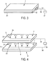
- Fig. 3 shows schematically and exemplarily how a lamella 9 can be provided with an LED 31.
- One surface of the lamella 9 is covered with a waveguide 30, wherein light of the LED 31 is coupled into the waveguide via a known incoupling structure 32.
- the surface of the waveguide 30, which faces the lamella 9, comprises outcoupling structures allowing the light within the waveguide 30 to leave the waveguide 30 in the direction of the lamella 9.
- the outcoupling structures are designed such that the lamella 9 is uniformly illumined by the outcoupled light.
- the LED 31 is connected via an electrical connection 35 with a power source 37 which can be controlled by the control unit 15.
- the power source 37 can be integrated into a frame of the building window or can be placed on a wall or within a wall close to the building window.
- the first side 7 of the lamella 9 is covered with the phosphorescent material and the lamella 9 is transparent to the outcoupled light, in order to allow the outcoupled light to illuminate the phosphorescent material arranged on the first side 7 of the lamella 9.
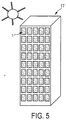
- Fig. 4 shows schematically and exemplarily a further possible arrangement of LEDs 33 on the lamellae 9.
- LEDs 33 for emitting light 34 are arranged on the first side 7 of the lamellae 9 .
- the LEDs 33 comprise preferentially an optical element like a lens for broadening the light 34 in order to more homogenously illuminate a neighboured lamella 9.
- the LEDs 33 are equidistantly arranged.
- the phosphorescent material is preferentially located on the second side 8 of the lamella 9 only, wherein the second side 8 of the lamella 9 is illuminated by the light 34 of the LEDs 33 of an adjacent lamella.
- the LEDs 33 are connected to a power source 39 via electrical connections 38, wherein the power source 39 can be controlled by the control unit 15.
- the power source 39 can be controlled by the control unit 15.
- Several power sources can be provided for controlling the different LEDs 33 individually. It is also possible that the LEDs of a lamella are simultaneously controlled and are connected to the same power source. In a further embodiment, all LEDs of all lamellae can be connected to the same power source being controlled by the control unit 15.
- the power source 39 can be integrated into a frame of the building window or can be placed on a wall or within a wall close to the building window.
- the phosphorescent material 2 can be uniformly distributed on the respective lamella or the photoluminescent material can be coated in a pattern.
- the phosphorescent material 2 can form letters, signs et cetera.
- the building window 1, the clock 10, the light sensors 10, 11, 12, the presence sensor 13, the movement sensor 14, the sun blind 6 and the control unit 15 can be regarded as a lighting system for providing an ambience lighting.
- the lighting system for providing an ambience lighting can further comprise the above mentioned LEDs which can be controlled by the control unit 15.
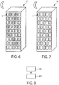
- Fig. 5 shows schematically and exemplarily a building 17 comprising several building windows 1 during the day.
- the sides of the lamellae 9, which comprise the phosphorescent material 2 are faced to the outside of the building such that the phosphorescent material can be charged up.
- the phosphorescent material 2 emits phosphorescent light.
- different building windows 1 can emit different colors.
- different building windows can comprise different phosphorescent materials.
- the control unit can be adapted such that the phosphorescent material of all building windows is directed to the outside or such that only some of the building windows direct their phosphorescent material to the outside.
- Fig. 6 an embodiment is shown, wherein some of the different building windows show different colors caused by emitted phosphorescent light and some further building windows do not show phosphorescent light.
- Fig. 7 shows schematically and exemplarily a further embodiment of a building comprising the building windows 1 during the night.
- the building 18 shown in Fig. 7 comprises several building windows 1, which have the same phosphorescent material and which provide therefore the same color.
- some building windows show the side with the phosphorescent material to the outside and some other building windows show the side with the phosphorescent material to the inside of the building, thereby generating a pattern which is visible from the outside of the building.
- the control unit 15 can be adapted such that a desired pattern is generated, which is visible from the outside of the buildings 17 and 18.
- Fig. 8 shows a flowchart exemplarily illustrating a method for modifying the appearance of a building.
- step 101 at least one of a time signal, a light signal, a presence signal and a movement signal are generated by at least one of the time providing unit 19, the light sensors 10, 11, 12, the presence sensor 13 and the movement sensor 14, wherein the light signal is indicative of ambient light and/or light emitted by the phosphorescent material, the presence signal is indicative of a presence of an object within a predefined area and the movement signal is indicative of a movement of an object within a predefined area.
- step 102 the sun blind 6 is controlled based on at least one of the time signal, the light signal, the presence signal and the movement signal.
- the use of the photoluminescent material in particular, of the phosphorescent material, allows to the create zero energy ambient glows for indoor and outdoor applications used in an automated system with daylight measurement, if LEDs are not used for charging up the photoluminescent material.
- an energy consumption as required by LEDs is preferentially not needed, if the sun blind with the photoluminescent material within the building window is used.
- the building window can provide an ambient lighting for buildings, in particular, an outdoor or indoor coloured architecture lighting can be provided.
- An indoor ambience can be created, which offers visitors an "experience”.
- the sun blind i.e. a sun shading element
- the control unit 15 can use a simple electronic circuit to read the signals emitted by, for example, the light sensors.
- the lamellae of the sun blind can be used like a sun screen with the lamellae rotating by 180 degrees.
- One side, or both sides, of the lamellae can be covered with a phosphorescent material.
- the light sensors can give a light signal which causes the control unit to rotate the lamellae.
- Rotation could be done automatically or mechanically. If both sides of the lamellae are covered with phosphorescent material, the colour can be changed to give the glow pattern a different geometry, for example, every day or every minute. If only one side of the lamellae is covered, a given pattern can be changed, thereby giving the effect of having a moving structure like on a display, wherein the building windows correspond to the pixels of the display. Indoor the effect is less visible, when the indoor lighting is on. But, in the evening, for example, when office hours are passed, and if lights are switched off, a glow could be still visible and give enough light for safety purposes.
- the light sensor can monitor the light emitted by the phosphorescent material and the lamellae can be controlled such that the most glowing surface faces the outdoor, or the indoor, side of the building window.
- the lamellae can be used for interior decoration.
- the window can comprise further pigments.
- These further pigments can be sprayed or painted on the sun blind or mixed within the material of the sun blind.
- the additional pigments can be sprayed or painted on lamella of a sun blind or mixed into a plastic material of the lamellae.
- the sun blind is comprised of several lamellae
- another kind of sun blind can be used like a continuous sun screen, wherein at least one side of the sun screen comprises photoluminescent material.
- the photoluminescent material is provided on a sun blind, which is integrated into the building window, in other embodiments the photoluminescent material can also directly be provided within the building window or by using another element not being a sun blind.
- the photoluminescent material is a phosphorescent material
- another photoluminescent material can be used like a fluorescent material.
- certain phosphorescent materials are mentioned, also other phosphorescent materials can be used within the building window.
- the phosphorescent material can comprise zinc sulfide and/or strontium aluminate.
- the photoluminescent material can also be a traser.
- the traser can contain tritium, which emits electrons if illuminated by light, wherein the emitted electrons cause phosphors, which are also contained in the trasers, to glow.
- the building window has two transparent glass plates
- the building window can comprise more than two transparent glass plates, in particular, three transparent glass plates. If more than two transparent glass plates form the building window, more than one internal space can be defined by these transparent glass plates and the photoluminescent material, in particular, sun blinds comprising the photoluminescent material, can be provided in one or more of the defined spaces between the transparent glass plates.
- the window is a building window within a building
- the window can also be used with another object like a car, a bus, a ship, an airplane, et cetera.
- a single unit or device may fulfill the functions of several items recited in the claims.
- the mere fact that certain measures are recited in mutually different dependent claims does not indicate that a combination of these measures cannot be used to advantage.
- the determinations like the determination of day or night and the control of the sun blind performed by one or several units or devices can be performed by any other number of units or devices.
- the determinations and/or the control of the sun blinds in accordance with the above described method for modifying the appearance of a building can be implemented as program code means of a computer program and/or as dedicated hardware.
- a computer program may be stored/distributed on a suitable medium, such as an optical storage medium or a solid-state medium, supplied together with or as part of other hardware, but may also be distributed in other forms, such as via the Internet or other wired or wireless telecommunication systems.
- a suitable medium such as an optical storage medium or a solid-state medium, supplied together with or as part of other hardware, but may also be distributed in other forms, such as via the Internet or other wired or wireless telecommunication systems.
- the invention relates to a window, in particular, a building window, wherein the window comprises photo luminescent material located within the window.
- the photoluminescent material is preferentially a phosphorescent material provided on a sun blind which is located within a sealed space between two transparent plates of the window.
- the photoluminescent material can be charged up by daylight and during the night the photoluminescent material can emanate light. Since the photoluminescent material is located within the window, the photoluminescent material is protected against environmental influences, in particular, against humidity, thereby increasing the lifetime of the photoluminescent material and, thus, of the window.
- the invention relates further to an object, in particular, a building, comprising the window, thereby giving the object an ambient glow.
Landscapes
- Engineering & Computer Science (AREA)
- Structural Engineering (AREA)
- Architecture (AREA)
- Civil Engineering (AREA)
- Blinds (AREA)
- Power-Operated Mechanisms For Wings (AREA)
- Securing Of Glass Panes Or The Like (AREA)
- Non-Portable Lighting Devices Or Systems Thereof (AREA)
- Building Environments (AREA)
Priority Applications (1)
| Application Number | Priority Date | Filing Date | Title |
|---|---|---|---|
| EP11746663.1A EP2601372B1 (en) | 2010-08-04 | 2011-07-25 | Window for an object |
Applications Claiming Priority (3)
| Application Number | Priority Date | Filing Date | Title |
|---|---|---|---|
| EP10171863 | 2010-08-04 | ||
| PCT/IB2011/053296 WO2012017351A1 (en) | 2010-08-04 | 2011-07-25 | Window for an object |
| EP11746663.1A EP2601372B1 (en) | 2010-08-04 | 2011-07-25 | Window for an object |
Publications (2)
| Publication Number | Publication Date |
|---|---|
| EP2601372A1 EP2601372A1 (en) | 2013-06-12 |
| EP2601372B1 true EP2601372B1 (en) | 2016-07-13 |
Family
ID=44504039
Family Applications (1)
| Application Number | Title | Priority Date | Filing Date |
|---|---|---|---|
| EP11746663.1A Not-in-force EP2601372B1 (en) | 2010-08-04 | 2011-07-25 | Window for an object |
Country Status (6)
| Country | Link |
|---|---|
| US (1) | US8820970B2 (enExample) |
| EP (1) | EP2601372B1 (enExample) |
| JP (1) | JP6030555B2 (enExample) |
| CN (1) | CN103038435B (enExample) |
| RU (1) | RU2568790C2 (enExample) |
| WO (1) | WO2012017351A1 (enExample) |
Families Citing this family (16)
| Publication number | Priority date | Publication date | Assignee | Title |
|---|---|---|---|---|
| US10303035B2 (en) | 2009-12-22 | 2019-05-28 | View, Inc. | Self-contained EC IGU |
| US11592723B2 (en) | 2009-12-22 | 2023-02-28 | View, Inc. | Automated commissioning of controllers in a window network |
| WO2018098089A1 (en) * | 2016-11-23 | 2018-05-31 | View, Inc. | Automated commissioning of controllers in a window network |
| US12498609B2 (en) | 2011-03-16 | 2025-12-16 | View Operating Corporation | Commissioning window networks |
| US12105394B2 (en) | 2011-03-16 | 2024-10-01 | View, Inc. | Commissioning window networks |
| CN104533265B (zh) * | 2014-12-29 | 2016-03-23 | 福建农林大学 | 一种发光竹制百叶帘 |
| CN104626328B (zh) * | 2014-12-29 | 2017-03-08 | 福建农林大学 | 一种发光竹质灯罩的加工工艺 |
| CN104526819B (zh) * | 2014-12-29 | 2017-02-01 | 福建农林大学 | 一种发光竹制百叶帘的制作工艺 |
| EP4089262A1 (en) | 2016-03-09 | 2022-11-16 | View, Inc. | Method of commissioning electrochromic windows |
| US10075013B2 (en) * | 2016-09-08 | 2018-09-11 | Ford Global Technologies, Llc | Vehicle apparatus for charging photoluminescent utilities |
| CN109282239A (zh) * | 2018-09-19 | 2019-01-29 | 武汉华风电子工程有限公司 | 一种新型船用智能信号灯及其控制方法 |
| EP3640423A1 (en) | 2018-10-19 | 2020-04-22 | Technoform Glass Insulation Holding GmbH | Self-illuminating spacer |
| CN114599851B (zh) | 2019-10-18 | 2025-01-10 | 亨特道格拉斯公司 | 发光的建筑结构遮盖物及其操作方法 |
| TW202206925A (zh) | 2020-03-26 | 2022-02-16 | 美商視野公司 | 多用戶端網路中之存取及傳訊 |
| CA3212568A1 (en) | 2021-03-23 | 2022-09-29 | Coty CHURCH | Lighted architectural-structure covering |
| CA3217693C (en) * | 2022-12-19 | 2024-11-05 | Morgan Solar Inc. | Blind systems for solar windows |
Family Cites Families (18)
| Publication number | Priority date | Publication date | Assignee | Title |
|---|---|---|---|---|
| DE1174476B (de) | 1957-01-25 | 1964-07-23 | Detag | Abblendvorrichtung mit einem in einer Doppelscheibe angeordneten Vorhang |
| JPS57137593A (en) * | 1981-02-16 | 1982-08-25 | Toshio Sugita | Blind |
| DE3125620A1 (de) * | 1981-06-30 | 1983-01-13 | Imchemie Kunststoff Gmbh, 5632 Wermelskirchen | Fenster, insbesondere lichtkuppel |
| JPS5931390A (ja) * | 1982-08-11 | 1984-02-20 | 杉田 利男 | ブラインド |
| JP3017351U (ja) * | 1995-04-24 | 1995-10-24 | 道彦 穴井 | 夜光ブランイド |
| JPH10311183A (ja) * | 1997-05-13 | 1998-11-24 | Yoshiharu Watanabe | 空気清浄調光サッシ |
| JP2000170466A (ja) * | 1998-12-03 | 2000-06-20 | Sanyo Electric Co Ltd | 採光窓 |
| JP2000303758A (ja) * | 1999-04-22 | 2000-10-31 | Ono:Kk | 発光ブラインド |
| DE29918618U1 (de) * | 1999-10-22 | 2000-02-03 | Otto Versand (GmbH & Co. KG), 22179 Hamburg | Fenstersichtschutz |
| US6601634B2 (en) * | 1999-12-17 | 2003-08-05 | Barbara E. Weidenbach | Illuminating window cover |
| US6639360B2 (en) * | 2001-01-31 | 2003-10-28 | Gentex Corporation | High power radiation emitter device and heat dissipating package for electronic components |
| JP2005016055A (ja) * | 2003-06-24 | 2005-01-20 | Takeuchi Kogyo Kk | ブラインド |
| CN2630442Y (zh) * | 2003-07-24 | 2004-08-04 | 格满林(南京)实业有限公司 | 内藏式百叶窗 |
| US20060043336A1 (en) * | 2004-08-27 | 2006-03-02 | Mide Technology Corporation | Controlled charging of a photoluminescent material |
| JP2007231613A (ja) * | 2006-03-01 | 2007-09-13 | Tokyo Electric Power Co Inc:The | ブラインド内蔵複層ガラス装置 |
| JP2010526405A (ja) * | 2007-05-03 | 2010-07-29 | コーニンクレッカ フィリップス エレクトロニクス エヌ ヴィ | 照明窓 |
| JP2009270382A (ja) * | 2008-05-09 | 2009-11-19 | Harumi Takeda | 電動ブラインド |
| DE102009019635B4 (de) * | 2009-04-30 | 2015-01-22 | Fraunhofer-Gesellschaft zur Förderung der angewandten Forschung e.V. | Optisches Bauelement sowie dessen Verwendung |
-
2011
- 2011-07-25 RU RU2013109268/12A patent/RU2568790C2/ru not_active IP Right Cessation
- 2011-07-25 JP JP2013522323A patent/JP6030555B2/ja not_active Expired - Fee Related
- 2011-07-25 WO PCT/IB2011/053296 patent/WO2012017351A1/en not_active Ceased
- 2011-07-25 CN CN201180038221.2A patent/CN103038435B/zh not_active Expired - Fee Related
- 2011-07-25 EP EP11746663.1A patent/EP2601372B1/en not_active Not-in-force
- 2011-07-25 US US13/812,170 patent/US8820970B2/en not_active Expired - Fee Related
Also Published As
| Publication number | Publication date |
|---|---|
| US8820970B2 (en) | 2014-09-02 |
| EP2601372A1 (en) | 2013-06-12 |
| CN103038435A (zh) | 2013-04-10 |
| JP6030555B2 (ja) | 2016-11-24 |
| US20130119870A1 (en) | 2013-05-16 |
| JP2013538305A (ja) | 2013-10-10 |
| RU2013109268A (ru) | 2014-09-10 |
| CN103038435B (zh) | 2016-08-03 |
| RU2568790C2 (ru) | 2015-11-20 |
| WO2012017351A1 (en) | 2012-02-09 |
Similar Documents
| Publication | Publication Date | Title |
|---|---|---|
| EP2601372B1 (en) | Window for an object | |
| CN100523425C (zh) | 窗户件 | |
| CN106164586B (zh) | 使用集成照明在窗口中产生不透明度和隐私的光防护物 | |
| EP2896776A1 (en) | Window structure body | |
| EP2745641B1 (en) | Methods and apparatus for control of illumination in an interior space | |
| KR101691274B1 (ko) | 유기 발광 소자 및 조명 장치 | |
| US20100118521A1 (en) | Illuminated window | |
| US20080184636A1 (en) | LED illuminated glazing materials | |
| JP2018055011A (ja) | 表示ブラインド | |
| KR20190133905A (ko) | 건축물의 차광 디스플레이 창 시스템 | |
| US11619777B2 (en) | Illuminable pane unit | |
| JP2009140745A (ja) | 発光ガラス装置 | |
| EP3755854B1 (en) | Window with lighting unit | |
| KR20130034403A (ko) | 도광판을 구비한 창문가림 장치 | |
| HK1079833A (en) | Window element |
Legal Events
| Date | Code | Title | Description |
|---|---|---|---|
| PUAI | Public reference made under article 153(3) epc to a published international application that has entered the european phase |
Free format text: ORIGINAL CODE: 0009012 |
|
| 17P | Request for examination filed |
Effective date: 20130304 |
|
| AK | Designated contracting states |
Kind code of ref document: A1 Designated state(s): AL AT BE BG CH CY CZ DE DK EE ES FI FR GB GR HR HU IE IS IT LI LT LU LV MC MK MT NL NO PL PT RO RS SE SI SK SM TR |
|
| 17Q | First examination report despatched |
Effective date: 20130612 |
|
| RAP1 | Party data changed (applicant data changed or rights of an application transferred) |
Owner name: KONINKLIJKE PHILIPS N.V. |
|
| DAX | Request for extension of the european patent (deleted) | ||
| GRAP | Despatch of communication of intention to grant a patent |
Free format text: ORIGINAL CODE: EPIDOSNIGR1 |
|
| INTG | Intention to grant announced |
Effective date: 20160211 |
|
| INTG | Intention to grant announced |
Effective date: 20160222 |
|
| INTG | Intention to grant announced |
Effective date: 20160229 |
|
| GRAS | Grant fee paid |
Free format text: ORIGINAL CODE: EPIDOSNIGR3 |
|
| GRAA | (expected) grant |
Free format text: ORIGINAL CODE: 0009210 |
|
| AK | Designated contracting states |
Kind code of ref document: B1 Designated state(s): AL AT BE BG CH CY CZ DE DK EE ES FI FR GB GR HR HU IE IS IT LI LT LU LV MC MK MT NL NO PL PT RO RS SE SI SK SM TR |
|
| REG | Reference to a national code |
Ref country code: GB Ref legal event code: FG4D |
|
| REG | Reference to a national code |
Ref country code: AT Ref legal event code: REF Ref document number: 812498 Country of ref document: AT Kind code of ref document: T Effective date: 20160715 Ref country code: CH Ref legal event code: EP |
|
| REG | Reference to a national code |
Ref country code: FR Ref legal event code: PLFP Year of fee payment: 6 |
|
| REG | Reference to a national code |
Ref country code: IE Ref legal event code: FG4D |
|
| REG | Reference to a national code |
Ref country code: DE Ref legal event code: R081 Ref document number: 602011028134 Country of ref document: DE Owner name: PHILIPS LIGHTING HOLDING B.V., NL Free format text: FORMER OWNER: KONINKLIJKE PHILIPS N.V., EINDHOVEN, NL |
|
| RAP2 | Party data changed (patent owner data changed or rights of a patent transferred) |
Owner name: PHILIPS LIGHTING HOLDING B.V. |
|
| REG | Reference to a national code |
Ref country code: DE Ref legal event code: R096 Ref document number: 602011028134 Country of ref document: DE |
|
| PGFP | Annual fee paid to national office [announced via postgrant information from national office to epo] |
Ref country code: GB Payment date: 20160729 Year of fee payment: 6 |
|
| REG | Reference to a national code |
Ref country code: GB Ref legal event code: 732E Free format text: REGISTERED BETWEEN 20161006 AND 20161012 |
|
| REG | Reference to a national code |
Ref country code: LT Ref legal event code: MG4D |
|
| REG | Reference to a national code |
Ref country code: NL Ref legal event code: MP Effective date: 20160713 |
|
| PGFP | Annual fee paid to national office [announced via postgrant information from national office to epo] |
Ref country code: FR Payment date: 20160728 Year of fee payment: 6 |
|
| REG | Reference to a national code |
Ref country code: AT Ref legal event code: MK05 Ref document number: 812498 Country of ref document: AT Kind code of ref document: T Effective date: 20160713 |
|
| PG25 | Lapsed in a contracting state [announced via postgrant information from national office to epo] |
Ref country code: BE Free format text: LAPSE BECAUSE OF NON-PAYMENT OF DUE FEES Effective date: 20160731 |
|
| PG25 | Lapsed in a contracting state [announced via postgrant information from national office to epo] |
Ref country code: IT Free format text: LAPSE BECAUSE OF FAILURE TO SUBMIT A TRANSLATION OF THE DESCRIPTION OR TO PAY THE FEE WITHIN THE PRESCRIBED TIME-LIMIT Effective date: 20160713 Ref country code: NO Free format text: LAPSE BECAUSE OF FAILURE TO SUBMIT A TRANSLATION OF THE DESCRIPTION OR TO PAY THE FEE WITHIN THE PRESCRIBED TIME-LIMIT Effective date: 20161013 Ref country code: FI Free format text: LAPSE BECAUSE OF FAILURE TO SUBMIT A TRANSLATION OF THE DESCRIPTION OR TO PAY THE FEE WITHIN THE PRESCRIBED TIME-LIMIT Effective date: 20160713 Ref country code: NL Free format text: LAPSE BECAUSE OF FAILURE TO SUBMIT A TRANSLATION OF THE DESCRIPTION OR TO PAY THE FEE WITHIN THE PRESCRIBED TIME-LIMIT Effective date: 20160713 Ref country code: IS Free format text: LAPSE BECAUSE OF FAILURE TO SUBMIT A TRANSLATION OF THE DESCRIPTION OR TO PAY THE FEE WITHIN THE PRESCRIBED TIME-LIMIT Effective date: 20161113 Ref country code: LT Free format text: LAPSE BECAUSE OF FAILURE TO SUBMIT A TRANSLATION OF THE DESCRIPTION OR TO PAY THE FEE WITHIN THE PRESCRIBED TIME-LIMIT Effective date: 20160713 Ref country code: RS Free format text: LAPSE BECAUSE OF FAILURE TO SUBMIT A TRANSLATION OF THE DESCRIPTION OR TO PAY THE FEE WITHIN THE PRESCRIBED TIME-LIMIT Effective date: 20160713 Ref country code: HR Free format text: LAPSE BECAUSE OF FAILURE TO SUBMIT A TRANSLATION OF THE DESCRIPTION OR TO PAY THE FEE WITHIN THE PRESCRIBED TIME-LIMIT Effective date: 20160713 |
|
| PGFP | Annual fee paid to national office [announced via postgrant information from national office to epo] |
Ref country code: DE Payment date: 20160930 Year of fee payment: 6 |
|
| PG25 | Lapsed in a contracting state [announced via postgrant information from national office to epo] |
Ref country code: PT Free format text: LAPSE BECAUSE OF FAILURE TO SUBMIT A TRANSLATION OF THE DESCRIPTION OR TO PAY THE FEE WITHIN THE PRESCRIBED TIME-LIMIT Effective date: 20161114 Ref country code: LV Free format text: LAPSE BECAUSE OF FAILURE TO SUBMIT A TRANSLATION OF THE DESCRIPTION OR TO PAY THE FEE WITHIN THE PRESCRIBED TIME-LIMIT Effective date: 20160713 Ref country code: GR Free format text: LAPSE BECAUSE OF FAILURE TO SUBMIT A TRANSLATION OF THE DESCRIPTION OR TO PAY THE FEE WITHIN THE PRESCRIBED TIME-LIMIT Effective date: 20161014 Ref country code: ES Free format text: LAPSE BECAUSE OF FAILURE TO SUBMIT A TRANSLATION OF THE DESCRIPTION OR TO PAY THE FEE WITHIN THE PRESCRIBED TIME-LIMIT Effective date: 20160713 Ref country code: SE Free format text: LAPSE BECAUSE OF FAILURE TO SUBMIT A TRANSLATION OF THE DESCRIPTION OR TO PAY THE FEE WITHIN THE PRESCRIBED TIME-LIMIT Effective date: 20160713 Ref country code: PL Free format text: LAPSE BECAUSE OF FAILURE TO SUBMIT A TRANSLATION OF THE DESCRIPTION OR TO PAY THE FEE WITHIN THE PRESCRIBED TIME-LIMIT Effective date: 20160713 Ref country code: AT Free format text: LAPSE BECAUSE OF FAILURE TO SUBMIT A TRANSLATION OF THE DESCRIPTION OR TO PAY THE FEE WITHIN THE PRESCRIBED TIME-LIMIT Effective date: 20160713 Ref country code: BE Free format text: LAPSE BECAUSE OF FAILURE TO SUBMIT A TRANSLATION OF THE DESCRIPTION OR TO PAY THE FEE WITHIN THE PRESCRIBED TIME-LIMIT Effective date: 20160713 |
|
| REG | Reference to a national code |
Ref country code: CH Ref legal event code: PL |
|
| REG | Reference to a national code |
Ref country code: DE Ref legal event code: R097 Ref document number: 602011028134 Country of ref document: DE |
|
| PG25 | Lapsed in a contracting state [announced via postgrant information from national office to epo] |
Ref country code: CH Free format text: LAPSE BECAUSE OF NON-PAYMENT OF DUE FEES Effective date: 20160731 Ref country code: EE Free format text: LAPSE BECAUSE OF FAILURE TO SUBMIT A TRANSLATION OF THE DESCRIPTION OR TO PAY THE FEE WITHIN THE PRESCRIBED TIME-LIMIT Effective date: 20160713 Ref country code: MC Free format text: LAPSE BECAUSE OF FAILURE TO SUBMIT A TRANSLATION OF THE DESCRIPTION OR TO PAY THE FEE WITHIN THE PRESCRIBED TIME-LIMIT Effective date: 20160713 Ref country code: LI Free format text: LAPSE BECAUSE OF NON-PAYMENT OF DUE FEES Effective date: 20160731 Ref country code: RO Free format text: LAPSE BECAUSE OF FAILURE TO SUBMIT A TRANSLATION OF THE DESCRIPTION OR TO PAY THE FEE WITHIN THE PRESCRIBED TIME-LIMIT Effective date: 20160713 |
|
| REG | Reference to a national code |
Ref country code: IE Ref legal event code: MM4A |
|
| PLBE | No opposition filed within time limit |
Free format text: ORIGINAL CODE: 0009261 |
|
| STAA | Information on the status of an ep patent application or granted ep patent |
Free format text: STATUS: NO OPPOSITION FILED WITHIN TIME LIMIT |
|
| PG25 | Lapsed in a contracting state [announced via postgrant information from national office to epo] |
Ref country code: DK Free format text: LAPSE BECAUSE OF FAILURE TO SUBMIT A TRANSLATION OF THE DESCRIPTION OR TO PAY THE FEE WITHIN THE PRESCRIBED TIME-LIMIT Effective date: 20160713 Ref country code: SK Free format text: LAPSE BECAUSE OF FAILURE TO SUBMIT A TRANSLATION OF THE DESCRIPTION OR TO PAY THE FEE WITHIN THE PRESCRIBED TIME-LIMIT Effective date: 20160713 Ref country code: BG Free format text: LAPSE BECAUSE OF FAILURE TO SUBMIT A TRANSLATION OF THE DESCRIPTION OR TO PAY THE FEE WITHIN THE PRESCRIBED TIME-LIMIT Effective date: 20161013 Ref country code: SM Free format text: LAPSE BECAUSE OF FAILURE TO SUBMIT A TRANSLATION OF THE DESCRIPTION OR TO PAY THE FEE WITHIN THE PRESCRIBED TIME-LIMIT Effective date: 20160713 Ref country code: CZ Free format text: LAPSE BECAUSE OF FAILURE TO SUBMIT A TRANSLATION OF THE DESCRIPTION OR TO PAY THE FEE WITHIN THE PRESCRIBED TIME-LIMIT Effective date: 20160713 |
|
| 26N | No opposition filed |
Effective date: 20170418 |
|
| PG25 | Lapsed in a contracting state [announced via postgrant information from national office to epo] |
Ref country code: IE Free format text: LAPSE BECAUSE OF NON-PAYMENT OF DUE FEES Effective date: 20160725 |
|
| PG25 | Lapsed in a contracting state [announced via postgrant information from national office to epo] |
Ref country code: SI Free format text: LAPSE BECAUSE OF FAILURE TO SUBMIT A TRANSLATION OF THE DESCRIPTION OR TO PAY THE FEE WITHIN THE PRESCRIBED TIME-LIMIT Effective date: 20160713 Ref country code: LU Free format text: LAPSE BECAUSE OF NON-PAYMENT OF DUE FEES Effective date: 20160725 |
|
| REG | Reference to a national code |
Ref country code: DE Ref legal event code: R119 Ref document number: 602011028134 Country of ref document: DE |
|
| GBPC | Gb: european patent ceased through non-payment of renewal fee |
Effective date: 20170725 |
|
| REG | Reference to a national code |
Ref country code: FR Ref legal event code: ST Effective date: 20180330 |
|
| PG25 | Lapsed in a contracting state [announced via postgrant information from national office to epo] |
Ref country code: DE Free format text: LAPSE BECAUSE OF NON-PAYMENT OF DUE FEES Effective date: 20180201 Ref country code: GB Free format text: LAPSE BECAUSE OF NON-PAYMENT OF DUE FEES Effective date: 20170725 |
|
| PG25 | Lapsed in a contracting state [announced via postgrant information from national office to epo] |
Ref country code: FR Free format text: LAPSE BECAUSE OF NON-PAYMENT OF DUE FEES Effective date: 20170731 Ref country code: HU Free format text: LAPSE BECAUSE OF FAILURE TO SUBMIT A TRANSLATION OF THE DESCRIPTION OR TO PAY THE FEE WITHIN THE PRESCRIBED TIME-LIMIT; INVALID AB INITIO Effective date: 20110725 Ref country code: CY Free format text: LAPSE BECAUSE OF FAILURE TO SUBMIT A TRANSLATION OF THE DESCRIPTION OR TO PAY THE FEE WITHIN THE PRESCRIBED TIME-LIMIT Effective date: 20160713 |
|
| PG25 | Lapsed in a contracting state [announced via postgrant information from national office to epo] |
Ref country code: TR Free format text: LAPSE BECAUSE OF FAILURE TO SUBMIT A TRANSLATION OF THE DESCRIPTION OR TO PAY THE FEE WITHIN THE PRESCRIBED TIME-LIMIT Effective date: 20160713 Ref country code: MK Free format text: LAPSE BECAUSE OF FAILURE TO SUBMIT A TRANSLATION OF THE DESCRIPTION OR TO PAY THE FEE WITHIN THE PRESCRIBED TIME-LIMIT Effective date: 20160713 Ref country code: MT Free format text: LAPSE BECAUSE OF NON-PAYMENT OF DUE FEES Effective date: 20160731 |
|
| PG25 | Lapsed in a contracting state [announced via postgrant information from national office to epo] |
Ref country code: AL Free format text: LAPSE BECAUSE OF FAILURE TO SUBMIT A TRANSLATION OF THE DESCRIPTION OR TO PAY THE FEE WITHIN THE PRESCRIBED TIME-LIMIT Effective date: 20160713 |