EP2599559A1 - Anlage zur Oberflächenbehandlung von Gegenständen - Google Patents
Anlage zur Oberflächenbehandlung von Gegenständen Download PDFInfo
- Publication number
- EP2599559A1 EP2599559A1 EP12007788.8A EP12007788A EP2599559A1 EP 2599559 A1 EP2599559 A1 EP 2599559A1 EP 12007788 A EP12007788 A EP 12007788A EP 2599559 A1 EP2599559 A1 EP 2599559A1
- Authority
- EP
- European Patent Office
- Prior art keywords
- maintenance
- treatment
- atmosphere
- unit
- passage
- Prior art date
- Legal status (The legal status is an assumption and is not a legal conclusion. Google has not performed a legal analysis and makes no representation as to the accuracy of the status listed.)
- Granted
Links
Images


Classifications
-
- B—PERFORMING OPERATIONS; TRANSPORTING
- B05—SPRAYING OR ATOMISING IN GENERAL; APPLYING FLUENT MATERIALS TO SURFACES, IN GENERAL
- B05B—SPRAYING APPARATUS; ATOMISING APPARATUS; NOZZLES
- B05B15/00—Details of spraying plant or spraying apparatus not otherwise provided for; Accessories
- B05B15/14—Arrangements for preventing or controlling structural damage to spraying apparatus or its outlets, e.g. for breaking at desired places; Arrangements for handling or replacing damaged parts
-
- B—PERFORMING OPERATIONS; TRANSPORTING
- B05—SPRAYING OR ATOMISING IN GENERAL; APPLYING FLUENT MATERIALS TO SURFACES, IN GENERAL
- B05B—SPRAYING APPARATUS; ATOMISING APPARATUS; NOZZLES
- B05B13/00—Machines or plants for applying liquids or other fluent materials to surfaces of objects or other work by spraying, not covered by groups B05B1/00 - B05B11/00
- B05B13/02—Means for supporting work; Arrangement or mounting of spray heads; Adaptation or arrangement of means for feeding work
- B05B13/04—Means for supporting work; Arrangement or mounting of spray heads; Adaptation or arrangement of means for feeding work the spray heads being moved during spraying operation
- B05B13/0431—Means for supporting work; Arrangement or mounting of spray heads; Adaptation or arrangement of means for feeding work the spray heads being moved during spraying operation with spray heads moved by robots or articulated arms, e.g. for applying liquid or other fluent material to three-dimensional [3D] surfaces
- B05B13/0433—Means for supporting work; Arrangement or mounting of spray heads; Adaptation or arrangement of means for feeding work the spray heads being moved during spraying operation with spray heads moved by robots or articulated arms, e.g. for applying liquid or other fluent material to three-dimensional [3D] surfaces the work being vehicle components, e.g. vehicle bodies
-
- B—PERFORMING OPERATIONS; TRANSPORTING
- B05—SPRAYING OR ATOMISING IN GENERAL; APPLYING FLUENT MATERIALS TO SURFACES, IN GENERAL
- B05B—SPRAYING APPARATUS; ATOMISING APPARATUS; NOZZLES
- B05B13/00—Machines or plants for applying liquids or other fluent materials to surfaces of objects or other work by spraying, not covered by groups B05B1/00 - B05B11/00
- B05B13/02—Means for supporting work; Arrangement or mounting of spray heads; Adaptation or arrangement of means for feeding work
- B05B13/04—Means for supporting work; Arrangement or mounting of spray heads; Adaptation or arrangement of means for feeding work the spray heads being moved during spraying operation
- B05B13/0447—Installation or apparatus for applying liquid or other fluent material to conveyed separate articles
- B05B13/0452—Installation or apparatus for applying liquid or other fluent material to conveyed separate articles the objects being vehicle components, e.g. vehicle bodies
-
- B—PERFORMING OPERATIONS; TRANSPORTING
- B05—SPRAYING OR ATOMISING IN GENERAL; APPLYING FLUENT MATERIALS TO SURFACES, IN GENERAL
- B05B—SPRAYING APPARATUS; ATOMISING APPARATUS; NOZZLES
- B05B16/00—Spray booths
- B05B16/40—Construction elements specially adapted therefor, e.g. floors, walls or ceilings
-
- B—PERFORMING OPERATIONS; TRANSPORTING
- B05—SPRAYING OR ATOMISING IN GENERAL; APPLYING FLUENT MATERIALS TO SURFACES, IN GENERAL
- B05D—PROCESSES FOR APPLYING FLUENT MATERIALS TO SURFACES, IN GENERAL
- B05D3/00—Pretreatment of surfaces to which liquids or other fluent materials are to be applied; After-treatment of applied coatings, e.g. intermediate treating of an applied coating preparatory to subsequent applications of liquids or other fluent materials
- B05D3/04—Pretreatment of surfaces to which liquids or other fluent materials are to be applied; After-treatment of applied coatings, e.g. intermediate treating of an applied coating preparatory to subsequent applications of liquids or other fluent materials by exposure to gases
- B05D3/0466—Pretreatment of surfaces to which liquids or other fluent materials are to be applied; After-treatment of applied coatings, e.g. intermediate treating of an applied coating preparatory to subsequent applications of liquids or other fluent materials by exposure to gases the gas being a non-reacting gas
-
- B—PERFORMING OPERATIONS; TRANSPORTING
- B05—SPRAYING OR ATOMISING IN GENERAL; APPLYING FLUENT MATERIALS TO SURFACES, IN GENERAL
- B05D—PROCESSES FOR APPLYING FLUENT MATERIALS TO SURFACES, IN GENERAL
- B05D3/00—Pretreatment of surfaces to which liquids or other fluent materials are to be applied; After-treatment of applied coatings, e.g. intermediate treating of an applied coating preparatory to subsequent applications of liquids or other fluent materials
- B05D3/04—Pretreatment of surfaces to which liquids or other fluent materials are to be applied; After-treatment of applied coatings, e.g. intermediate treating of an applied coating preparatory to subsequent applications of liquids or other fluent materials by exposure to gases
- B05D3/0486—Operating the coating or treatment in a controlled atmosphere
Definitions
- the treatment room is often formed as a paint tunnel, through which the body parts to be painted are conveyed in the passage through.
- multiaxial industrial robots are present as working units in such installations, which as an application robot carry an application device for paints or as a handling robot a gripping device.
- an application robot carry an application device for paints or as a handling robot a gripping device.
- robots can carry radiation sources that are used to irradiate objects to dry coatings.
- UV-curing coatings can be cured in an inert gas atmosphere by UV light sources.
- Such work units are increasingly being used in areas used, in which a special atmosphere prevails. This includes all atmospheres that are different from a normal atmosphere surrounding the treatment room.
- the atmosphere in the treatment room includes, among other things, paint not applied to the objects, which in professional circles is referred to as "overspray".
- the overspray is detected by an air stream supplied to the paint booth and fed to a separation.
- the special atmosphere is formed there by the solvent-containing and overspray-laden air.
- work units are also used in areas where other special atmospheres prevail. These include e.g. Areas where there is a lot of pollution, a toxic, low-oxygen and / or health-threatening atmosphere prevails or high temperatures. It may also happen that work units must be used under reduced or elevated pressure, under water or in areas with radioactive radiation.
- the maintenance or operating person may wear a protective clothing adapted to the prevailing special atmosphere.
- the working unit can thus be moved out of the treatment room and thus out of the atmosphere prevailing there, so that the working unit is easily located in the maintenance zone outside the treatment room and safely accessible to a serviceman or operator for manual work.
- the maintenance zone is preferably arranged above or below the treatment space. This is particularly favorable in cases where there is an inert gas atmosphere in the treatment room that is lighter or heavier than air.
- the conveyor unit is a lift unit, by which the working unit is movable in the vertical direction.
- sealing means are present, by which the at least one maintenance passage is at least then sealed against the ambient atmosphere, if the working unit a working position within the treatment room or a maintenance position in the Maintenance zone occupies.
- the conveyor unit may comprise the sealing means.
- the conveyor unit comprises a carriage, which leads as a sealing means at least one sealing wall with it.
- This sealing wall can then close the maintenance passage in one of the above-mentioned positions of the working unit.
- the maintenance passage may be formed as a double lock. In this case, an atmosphere exchange can also be inhibited while the work unit passes through the maintenance passage.
- the special atmosphere is an inert gas atmosphere.
- FIGS. 1 and 2 There is an example of a surface treatment facility of objects a painting system shown, which is generally designated 10.
- objects 12 are painted, which are shown only very schematically in the present embodiment.
- objects 12 to be painted are vehicle bodies and in particular body parts, such as bumpers.
- the objects to be painted 12 have been cleaned and degreased in non-specifically shown pretreatment stations, for example, which are upstream of the paint shop 10.
- the paint shop 10 includes a treatment booth as a paint booth 14 with a treatment room 16 in the form of a paint tunnel 18, which is bounded by vertical side walls 20, a horizontal cabin floor 22 and a horizontal cabin ceiling 24.
- a special atmosphere can be generated and maintained in the painting tunnel 18 in a manner known per se.
- a special atmosphere should be understood as any atmosphere that differs from the outside atmosphere surrounding the treatment room 16.
- a special atmosphere may in particular be an inert gas atmosphere, but also a clean-room atmosphere or other working atmospheres are included.
- the cabin ceiling 24 is formed for example in the usual way as the lower boundary of an air supply space with filter cover.
- Conditioned air enters the paint tunnel 18 from the air supply space and flows through it from top to bottom, the air receiving overspray during painting.
- the laden with overspray air then passes into the area below the painting tunnel 18, where then instead of the inert gas 26 are a separator can, by means of which the air can be freed from the overspray.
- the special atmosphere is thus formed by the solvent-containing and overspray-laden tunnel air.
- a transport system 28 are transported to the objects to be painted 12 from an input side of the painting tunnel 18 to an output side of the painting tunnel 18, which are not recognizable due to the selected sections.
- working units 30 which in the present embodiment are in the form of multi-axis application robots 32, by means of which the articles 12 can be coated with lacquer. Both the transport system 28 and the application robot 32 are known per se, which is why a more detailed explanation is unnecessary.
- the work units 30 may also be set up for purposes other than the application.
- the working units 30 may also be formed by gripping units, by means of which the objects 12 can be moved and handled in the treatment space 16.
- the paint booth 14 may comprise maintenance passages 34. Through these service passages 34, the application robots 32 may be moved out of the painting tunnel 18 so that a particular application robot 32 can be moved out of the inert gas atmosphere into a maintenance zone 36 in which normal atmosphere prevails. There, the application robot 32 is safely accessible to a maintenance or operator who can perform the necessary work on the relevant application robot 32.
- the maintenance passages 34 are present in the cabin ceiling 24 above the application robots 32 and lead to the maintenance zone 36, which is located above the cabin ceiling 24.
- the application robots 32 are each arranged on conveyor units 38, by means of which the application robots 32 can be moved out of the treatment space 16 through the associated maintenance passage 34.
- the conveyor units 38 are designed as lift units 40, by means of which the application robot 32 can be moved in the vertical direction.
- the lift units 40 each comprise a slide carrier 42, on each of which an application robot 32 is arranged.
- the carriage carrier 42 with the application robot 32 can be moved up or down along a vertical guide pillar 44.
- drive means are present, as they are known in and of themselves.
- the lift unit 40 comprises sealing means in the form of a first, upper sealing wall 46 and a second, lower sealing wall 48.
- the carriage carrier 42 carries the upper sealing wall 46 with it, which is arranged vertically above the application robot 32 and seals the associated maintenance passage 34, if the Slide carrier 42 and the application robot 32 occupy a working position in which the application robot 32 is located within the painting tunnel 18. This is in FIG. 1 to recognize.
- the carriage carrier 42 also carries the lower sealing wall 48, which is arranged vertically below the application robot 32 and seals the associated maintenance passage 34 when the carriage carrier 42 and the application robot 32 assume a maintenance position in which the application robot 32 is in the maintenance zone 36 is outside the paint tunnel 18. This is in FIG. 2 to recognize at the right there shown lift unit 40.
- other sealing means may also be present, which operate in particular independently of the conveying units 38.
- the service passages 34 may be selectively sealed or released by doors or sliders or the like.
- the carriage carrier 42 carrying the application robot 32 in question is moved upwards out of the painting tunnel 18 together with the latter.
- the maintenance passage 34 becomes during the upward movement of the carriage carrier 42 for the passage of time briefly opened when the upper sealing wall 46 moves upward and the maintenance passage 34 releases.
- the carriage carrier 42 has moved with the application robot 32 through the maintenance passage 34, it is again closed by the lower sealing wall 48, so that no inert gas atmosphere can escape from the painting tunnel 18.
- the required work on the application robot 32 can then be carried out in normal atmosphere. Also, replacement of the processing unit 30 on the slide carrier 42, e.g. the replacement of an application robot 32 against a handling robot is thus possible in the maintenance zone 36 under normal atmosphere. This is useful, for example, if it becomes apparent that maintenance work on the application robot 32 takes longer. In this case, the necessary maintenance on the application robot 32 can be performed at rest off the system 10; the full operation of the system 10 can be resumed in a short time with the replacement application robot 32.
- the slide carrier 42 is moved back into the drying tunnel 18 with the application robot 32 until the maintenance passage 34 is closed by the upper sealing wall 46.
- FIGS. 1 and 2 shown embodiment of the paint shop 10 is designed for an inert gas atmosphere in the paint tunnel 18, which is heavier than air. Even with the passage of the slide carrier 42 and the application robot 32 through an open maintenance passage 34 then occurs only a reasonable amount of tunnel atmosphere from the Paint tunnel 18 to the outside, which are swirled by the slide carrier 42 and the application robot 32 and entrained when they pass through the maintenance passage 34.
- an inert gas in this case, for example, carbon dioxide into consideration.
- a modified paint shop 10 ' which is adapted to an inert gas, which is lighter than air.
- inert gas for example, helium comes into question.
- the application robot 32 can not be moved upwards out of the painting tunnel 18 by means of the lift units 40.
- the maintenance openings 34 are present in the tunnel floor 22.
- the maintenance zone 36 is located there below the tunnel floor 22 next to the inert gas system 26.
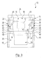
- the lower sealing wall 48 thus sits sealingly in the associated maintenance passage 34 when the carriage carrier 42 and the application robot 32 occupy a working position in which the application robot 32 is located within the painting tunnel 18; this shows FIG. 3 ,
- the upper sealing wall 46 fits sealingly in the associated maintenance passage 34 when the slide carrier 42 and the application robot 32 assume a maintenance position in which the application robot 32 is outside in the maintenance zone 36 the painting tunnel 18 is located.
- the service passages 34 may be provided in the sidewalls 20 and the carriage supports 42 may be horizontally moved on the horizontal guide pillars out of the drying tunnel 18 ,
- the maintenance passages 34 are in practice designed in each case as a double lock known per se, so that the tunnel atmosphere does not escape to the outside or is not contaminated from the outside by ambient atmosphere.
- the application robots 32 are considered as a working unit 30.
- the service passages 34 may also be arranged and dimensioned such that only the work tool guided by the robot, be it a spray unit for paints, a gripper unit, a radiation source, or the like, can be moved through the service passage 34 into the maintenance zone 36 during the operation Robot itself remains in the treatment room 16.
- the corresponding working tools form the respective working unit 30.
- a seal of the maintenance passage 34 is then expediently carried out by sealing flaps or the like, so that a corresponding Maintenance passage 34 can be optionally closed or released.
Landscapes
- Engineering & Computer Science (AREA)
- Robotics (AREA)
- Details Or Accessories Of Spraying Plant Or Apparatus (AREA)
- Automobile Manufacture Line, Endless Track Vehicle, Trailer (AREA)
- Coating Apparatus (AREA)
Abstract
Description
- Die Erfindung betrifft eine Anlage zur Oberflächenbehandlung, insbesondere zum Lackieren, von Gegenständen, insbesondere von Karosserieteilen, mit
- a) einer Behandlungskabine, die einen Behandlungsraum vorgibt;
- b) einem Transportsystem, mittels welchem die Gegenstände in den Behandlungsraum hinein und wieder aus diesem heraus transportierbar sind;
- c) wenigstens einer Arbeitseinheit, mittels welcher Arbeiten in dem Behandlungsraum durchführbar sind.
- Vom Markt her bekannt sind Anlagen dieser Art, welche zum Lackieren von Fahrzeugkarosserien und insbesondere von Karosserieteilen verwendet werden. Dort ist der Behandlungsraum häufig als Lackiertunnel ausgebildet, durch welchen die zu lackierenden Karosserieteile im Durchlauf hindurch gefördert werden.
- Als Arbeitseinheiten sind in solchen Anlagen beispielsweise mehrachsige Industrieroboter vorhanden, die als Applikationsroboter eine Applikationseinrichtung für Lacke oder als Handhabungsroboter eine Greifeinrichtung mit sich führen. Auch können solche Roboter Strahlungsquellen tragen, mit denen Gegenstände bestrahlt werden, um Beschichtungen zu trocknen. Beispielsweise können so UV-härtende Lacke in einer Inertgasatmosphäre durch UV-Lichtquellen gehärtet werden.
- Derartige Arbeitseinheiten werden vermehrt auch in Bereichen eingesetzt, in denen eine Sonderatmosphäre herrscht. Dazu zählen alle Atmosphären, die verschieden von einer den Behandlungsraum umgebenden Normalatmosphäre sind.
- Bereits bei einfachen Lackiervorgängen in Lackierkabinen umfasst die Atmosphäre im Behandlungsraum unter anderem nicht auf die Gegenstände applizierten Lack, der in Fachkreisen als "Overspray" bezeichnet wird. Der Overspray wird von einem der Lackierkabine zugeführten Luftstrom erfasst und einer Abscheidung zugeführt. So ist dort die Sonderatmosphäre durch die lösemittelhaltige und mit Overspray beladene Luft gebildet.
- Darüber hinaus werden Arbeitseinheiten aber auch in Bereichen eingesetzt, in denen andere Sonderatmosphären herrschen. Hierzu zählen z.B. Bereiche, in denen es zu einer großen Verschmutzung kommt, eine giftige, sauerstoffarme und/oder gesundheitsgefährdende Atmosphäre herrscht oder hohe Temperaturen vorliegen. Auch kann es vorkommen, dass Arbeitseinheiten unter vermindertem oder erhöhtem Druck, unter Wasser oder in Bereichen mit radioaktiver Strahlung eingesetzt werden müssen.
- Generell ist es schwierig bis unmöglich, an den Arbeitseinheiten Wartungs- und Servicearbeiten durchzuführen oder sonstige Einstellungen vorzunehmen, während sich diese in einer Sonderatmosphäre befinden. Daher muss die Produktion unterbrochen und die Sonderatmosphäre gegen eine für eine Wartungs- oder Bedienperson unschädliche Atmosphäre ausgetauscht werden, bevor ein Zugriff auf eine zu wartende Arbeitseinheit möglich ist. Wenn die erforderlichen Arbeiten an der Arbeitseinheit abgeschlossen sind, muss zunächst die Sonderatmosphäre im Behandlungsraum wiederhergestellt werden, bevor der weitere Betrieb der Anlage möglich ist. Ein derartiges Wiederherstellen der notwendigen Sonderatmosphäre kann jedoch bis zu einer Stunde dauern. Dies steht jedoch meist in keinem Verhältnis zu dem Zeitaufwand für Wartungstätigkeiten an der Arbeitseinheit, die meist nur wenige Minuten in Anspruch nehmen.
- Alternativ kann die Wartungs- oder Bedienperson zwar eine an die herrschende Sonderatmosphäre angepasste Schutzbekleidung tragen. Dies bedeutet jedoch erschwerte Arbeitsbedingungen für die Person, deren Bewegungsfreiheit zudem durch die Schutzkleidung eingeschränkt ist.
- Insgesamt sind daher Wartungsarbeiten oder dergleichen an den Arbeitseinheiten umständlich, zeitaufwendig und stören in hohem Maße den Betrieb der Anlage.
- Es ist daher Aufgabe der Erfindung, eine Anlage der eingangs genannten Art zu schaffen, welche den obigen Gedanken Rechnung trägt.
- Diese Aufgabe wird bei einer Anlage der eingangs genannten Art dadurch gelöst, dass
- d) die Behandlungskabine wenigstens einen Wartungsdurchgang zwischen dem Behandlungsraum und einer Wartungszone umfasst;
- e) eine Fördereinheit vorhanden ist, mittels welcher die wenigstens eine Arbeitseinheit durch den wenigstens einen Wartungsdurchgang hindurch aus dem Behandlungsraum heraus in die Wartungszone bewegbar ist.
- Erfindungsgemäß kann die Arbeitseinheit also aus dem Behandlungsraum und damit aus der dort herrschenden Atmosphäre heraus bewegt werden, so dass die Arbeitseinheit in der außerhalb des Behandlungsraumes liegenden Wartungszone leicht und gefahrlos für eine Wartungs- oder Bedienperson für manuelle Arbeiten zugänglich ist.
- Vorzugsweise ist die Wartungszone oberhalb oder unterhalb des Behandlungsraumes angeordnet. Dies ist insbesondere in Fällen günstig, in denen im Behandlungsraum eine Inertgasatmosphäre herrscht, die leichter bzw. schwerer als Luft ist.
- Dabei ist es günstig, wenn die Fördereinheit eine Lifteinheit ist, durch welche die Arbeitseinheit in vertikaler Richtung bewegbar ist.
- Um einen Austausch der Atmosphäre im Behandlungsraum mit der Umgebungsatmosphäre zu verhindern, ist es von Vorteil, wenn Dichtmittel vorhanden sind, durch welche der wenigstens eine Wartungsdurchgang zumindest dann gegen die Umgebungsatmosphäre abgedichtet ist, wenn die Arbeitseinheit eine Arbeitsstellung innerhalb des Behandlungsraumes oder eine Wartungsstellung in der Wartungszone einnimmt.
- Dabei kann die Fördereinheit die Dichtmittel umfassen.
- Vorzugsweise umfasst dann die Fördereinheit einen Schlitten, welcher als Dichtmittel wenigstens eine Dichtwand mit sich führt. Diese Dichtwand kann dann den Wartungsdurchgang in einer der oben genannten Stellungen der Arbeitseinheit verschließen.
- Alternativ oder ergänzend kann der Wartungsdurchgang als Doppelschleuse ausgebildet sein. In diesem Fall kann ein Atmosphärenaustausch auch unterbunden werden, währen die Arbeitseinheit den Wartungsdurchgang passiert.
- Die obigen Merkmale sind besonders von Vorteil, wenn in dem Behandlungsraum eine Sonderatmosphäre herrscht.
- Dazu ist es günstig, wenn ein System vorhanden ist, mittels welchem die Sonderatmosphäre in dem Behandlungsraum erzeugbar ist.
- Vorzugsweise ist die Sonderatmosphäre eine Inertgasatmosphäre.
- Nachfolgend werden Ausführungsbeispiele der Erfindung anhand der Zeichnungen näher erläutert. In diesen zeigen:
- Figur 1
- einen schematischen Vertikalschnitt einer Lackierkabine einer Lackieranlage gemäß einem ersten Ausführungsbeispiel, wobei sich zwei Applikationsroboter jeweils in einer Arbeitszone innerhalb eines Behandlungsraumes befinden;
- Figur 2
- einen der
Figur 1 entsprechenden Schnitt, wobei sich einer der Applikationsroboter in einer Wartungszone außerhalb und oberhalb des Behandlungsraumes befindet; - Figur 3
- einen schematischen Vertikalschnitt einer Lackierkabine einer Lackieranlage gemäß einem zweiten Ausführungsbeispiel, wobei sich zwei Applikationsroboter jeweils in einer Arbeitszone innerhalb eines Behandlungsraumes befinden;
- Figur 4
- einen der
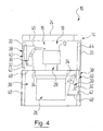
Figur 3 entsprechenden Schnitt, wobei sich einer der Applikationsroboter in einer Wartungszone außerhalb und unterhalb des Behandlungsraumes befindet. - Zunächst wird auf die
Figuren 1 und2 Bezug genommen. Dort ist als Beispiel für eine Anlage zur Oberflächenbehandlung von Gegenständen eine Lackieranlage gezeigt, die insgesamt mit 10 bezeichnet ist. In der Lackieranlage 10 werden Gegenstände 12 lackiert, welche beim vorliegenden Ausführungsbeispiel nur stark schematisch gezeigt sind. Als Beispiele für zu lackierende Gegenstände 12 seien Fahrzeugkarosserien und insbesondere Karosserieteile, wie z.B. Stoßfänger, genannt. Die zu lackierenden Gegenstände 12 wurden in nicht eigens gezeigten Vorbehandlungsstationen z.B. gereinigt und entfettet, die der Lackieranlage 10 vorgelagert sind. - Die Lackieranlage 10 umfasst als Behandlungskabine eine Lackierkabine 14 mit einem Behandlungsraum 16 in Form eines Lackiertunnels 18, welcher von vertikalen Seitenwänden 20, einem horizontalen Kabinenboden 22 und einer horizontalen Kabinendecke 24 begrenzt ist.
- Mittels eines nur stark schematisch unterhalb des Lackiertunnels 18 angedeuteten Systems 26 kann in dem Lackiertunnel 18 in an und für sich bekannter Weise eine Sonderatmosphäre erzeugt und aufrechterhalten werden. Als Sonderatmosphäre soll jede Atmosphäre verstanden werden, die sich von der den Behandlungsraum 16 umgebenden Außenatmosphäre unterscheidet. Eine Sonderatmosphäre kann insbesondere eine Inertgasatmosphäre sein, aber auch eine Reinraumatmosphäre oder sonstige Arbeitsatmosphären zählen dazu.
- Bei einer nicht eigens gezeigten Abwandlung ist die Kabinendecke 24 beispielsweise in üblicher Weise als untere Begrenzung eines Luftzuführraumes mit Filterdecke ausgebildet. Aus dem Luftzuführraum gelangt konditionierte Luft in den Lackiertunnel 18 und durchströmt diesen von oben nach unten, wobei die Luft beim Lackieren entstehenden Overspray aufnimmt. Die mit Overspray beladene Luft gelangt dann in den Bereich unterhalb des Lackiertunnels 18, wo sich dann anstelle des Inertgassystems 26 eine Abscheideeinrichtung befinden kann, mittels welcher die Luft von dem Overspray befreit werden kann. Diese Vorgehensweise ist aus dem Stand der Technik bekannt. In diesem Fall ist die Sonderatmosphäre also durch die lösemittelhaltige und mit Overspray beladene Tunnelluft gebildet.
- Es ist ein Transportsystem 28 vorhanden, mit dem zu lackierende Gegenstände 12 von einer Eingangsseite des Lackiertunnels 18 zu einer Ausgangsseite des Lackiertunnels 18 transportiert werden, die auf Grund der gewählten Schnitte nicht zu erkennen sind. Sowohl an der Eingangsseite als auch an der Ausgangsseite des Lackiertunnels 18 sind in an und für sich bekannter Weise entsprechende Durchgangsschleusen vorhanden, durch welche die zu lackierenden Gegenstände 12 in den Lackiertunnel 18 eingebracht und wieder aus diesen heraus bewegt werden können, wobei die Inertgasatmosphäre im Lackiertunnel 18 aufrecht erhalten bleibt.
- Im Inneren des Lackiertunnels 18 befinden sich Arbeitseinheiten 30, die beim vorliegenden Ausführungsbeispiel in Form von mehrachsigen Applikationsrobotern 32 vorhanden sind, mittels welchen die Gegenstände 12 mit Lack beschichtet werden können. Sowohl das Transportsystem 28 als auch die Applikationsroboter 32 sind an und für sich bekannt, weshalb sich eine nähere Erläuterung dazu erübrigt. Die Arbeitseinheiten 30 können auch für andere Zwecke als zur Applikation eingerichtet sein. Beispielsweise können die Arbeitseinheiten 30 auch durch Greifeinheiten gebildet sein, mittels welchen die Gegenstände 12 im Behandlungsraum 16 bewegt und gehandhabt werden können.
- Damit an den Applikationsrobotern 32 Wartungs- oder Servicearbeiten durchgeführt oder sonstige Einstellungen vorgenommen werden können, ohne dass hierzu die Inertgasatmosphäre im Lackiertunnel 18 entfernt und gegen Normalatmosphäre ausgetauscht werden muss, umfasst die Lackierkabine 14 Wartungsdurchgänge 34. Durch diese Wartungsdurchgänge 34 hindurch können die Applikationsroboter 32 aus dem Lackiertunnel 18 heraus bewegt werden, so dass ein bestimmter Applikationsroboter 32 aus der Inertgasatmosphäre heraus in eine Wartungszone 36 bewegt werden kann, in welcher Normalatmosphäre herrscht. Dort ist der Applikationsroboter 32 gefahrlos für eine Wartung- oder Bedienperson zugänglich, welche die notwendigen Arbeiten an dem betreffenden Applikationsroboter 32 vornehmen kann.
- Beim in den
Figuren 1 und2 gezeigten Ausführungsbeispiel sind die Wartungsdurchgänge 34 in der Kabinendecke 24 oberhalb der Applikationsroboter 32 vorhanden und führen zu der Wartungszone 36, die sich oberhalb der Kabinendecke 24 befindet. - Die Applikationsroboter 32 sind jeweils auf Fördereinheiten 38 angeordnet, mittels welchen die Applikationsroboter 32 durch den zugehörigen Wartungsdurchgang 34 hindurch aus dem Behandlungsraum 16 heraus bewegbar sind. Beim vorliegenden Ausführungsbeispiel sind die Fördereinheiten 38 als Lifteinheiten 40 ausgebildet, durch welche die Applikationsroboter 32 in vertikaler Richtung bewegt werden können.
- Die Lifteinheiten 40 umfassen jeweils einen Schlittenträger 42, auf denen jeweils ein Applikationsroboter 32 angeordnet ist. Der Schlittenträger 42 mit dem Applikationsroboter 32 kann entlang eines vertikalen Führungspfeilers 44 hoch oder herunter gefahren werden. Hierzu sind nicht eigens gezeigte Antriebsmittel vorhanden, wie sie an und für sich bekannt sind.
- Um die Wartungsdurchgänge 34 und damit den Lackiertunnel 18 gegen die Umgebungsatmosphäre abdichten zu können, sind Dichtmittel vorhanden, mit denen die Wartungsdurchgänge 34 dichtend verschlossen oder freigegeben werden können.
- Hierzu umfasst die Lifteinheit 40 Dichtmittel in Form einer ersten, oberen Dichtwand 46 und einer zweiten, unteren Dichtwand 48. Der Schlittenträger 42 führt die obere Dichtwand 46 mit sich, die vertikal über dem Applikationsroboter 32 angeordnet ist und den zugehörigen Wartungsdurchgang 34 abdichtet, wenn der Schlittenträger 42 und der Applikationsroboter 32 eine Arbeitsstellung einnehmen, in welcher sich der Applikationsroboter 32 innerhalb des Lackiertunnels 18 befindet. Dies ist in
Figur 1 zu erkennen. - Außerdem führt der Schlittenträger 42 auch die untere Dichtwand 48 mit sich, die vertikal unter dem Applikationsroboter 32 angeordnet ist und den zugehörigen Wartungsdurchgang 34 abdichtet, wenn der Schlittenträger 42 und der Applikationsroboter 32 eine Wartungsstellung einnehmen, in welcher sich der Applikationsroboter 32 in der Wartungszone 36 außerhalb des Lackiertunnels 18 befindet. Dies ist in
Figur 2 bei der dort rechts gezeigten Lifteinheit 40 zu erkennen. - Bei einer nicht eigens gezeigten Abwandlung können auch andere Dichtmittel vorhanden sein, die insbesondere unabhängig von den Fördereinheiten 38 arbeiten. Beispielsweise können die Wartungsdurchgänge 34 durch Türen oder Schieber oder dergleichen wahlweise dichtend verschlossen oder freigegeben werden.
- Wenn nun beim vorliegenden Ausführungsbeispiel an einem Applikationsroboter 32 Wartungs- oder Servicearbeiten durchgeführt oder sonstige Einstellungen vorgenommen werden sollen, wird der den fraglichen Applikationsroboter 32 tragende Schlittenträger 42 zusammen mit diesem aus dem Lackiertunnel 18 heraus nach oben gefahren. Der Wartungsdurchgang 34 wird bei der Aufwärtsbewegung des Schlittenträgers 42 für dessen Durchfahrt kurzzeitig geöffnet, wenn die obere Dichtwand 46 sich nach oben bewegt und den Wartungsdurchgang 34 freigibt. Wenn der Schlittenträger 42 mit dem Applikationsroboter 32 durch den Wartungsdurchgang 34 hindurch gefahren ist, ist dieser wieder durch die untere Dichtwand 48 verschlossen, so dass keine Inertgasatmosphäre aus dem Lackiertunnel 18 entweichen kann.
- In der Wartungszone 36 können die erforderlichen Arbeiten an dem Applikationsroboter 32 dann in Normalatmosphäre durchgeführt werden. Auch ein Austausch der Arbeitseinheit 30 auf dem Schlittenträger 42, so z.B. der Austausch eines Applikationsroboters 32 gegen einen Handhabungsroboter, ist so in der Wartungszone 36 unter Normalatmosphäre möglich. Dies bietet sich beispielsweise an, wenn sich abzeichnet, dass Wartungsarbeiten an dem Applikationsroboter 32 länger dauern. In diesem Fall kann die notwendige Wartung an dem Applikationsroboter 32 in Ruhe abseits der Anlage 10 durchgeführt werden; der volle Betrieb der Anlage 10 kann in kurzer Zeit mit dem Ersatz-Applikationsroboter 32 wieder aufgenommen werden.
- Wenn die Arbeiten an dem Applikationsroboter 32 in der Wartungszone 36 abgeschlossen sind, wird der Schlittenträger 42 mit dem Applikationsroboter 32 wieder nach unten in den Trockentunnel 18 hinein bewegt, bis der Wartungsdurchgang 34 durch die obere Dichtwand 46 verschlossen ist.
- Das in den
Figuren 1 und2 gezeigte Ausführungsbeispiel der Lackieranlage 10 ist für eine Inertgasatmosphäre im Lackiertunnel 18 konzipiert, welche schwerer als Luft ist. Auch bei der Durchfahrt des Schlittenträgers 42 und des Applikationsroboters 32 durch einen offenen Wartungsdurchgang 34 tritt dann nur eine vertretbare Menge der Tunnelatmosphäre aus dem Lackiertunnel 18 nach außen, die von dem Schlittenträger 42 und dem Applikationsroboter 32 aufgewirbelt und mitgerissen werden, wenn diese den Wartungsdurchgang 34 passieren. Als Inertgas kommt in diesem Fall beispielsweise Kohlendioxid in Betracht. - In den
Figuren 3 und4 ist als zweites Ausführungsbeispiel eine abgewandelte Lackieranlage 10' gezeigt, welche an ein Inertgas angepasst ist, welches leichter als Luft ist. Als solches Inertgas kommt beispielsweise Helium in Frage. - Bei der Lackieranlage 10' sind Komponenten, die denjenigen der Lackieranlage 10 nach den
Figuren 1 und2 entsprechen, mit denselben Bezugszeichen gekennzeichnet. - Im Unterschied zu Lackieranlage 10 können die Applikationsroboter 32 mittels der Lifteinheiten 40 nicht nach oben, sondern nach unten aus dem Lackiertunnel 18 heraus bewegt werden. Dazu sind die Wartungsöffnungen 34 im Tunnelboden 22 vorhanden. Die Wartungszone 36 befindet sich dort unterhalb des Tunnelbodens 22 neben dem Inertgassystem 26.
- Bei dieser Ausbildung sitzt die untere Dichtwand 48 somit dichtend in dem zugehörigen Wartungsdurchgang 34 ein, wenn der Schlittenträger 42 und der Applikationsroboter 32 eine Arbeitsstellung einnehmen, in welcher sich der Applikationsroboters 32 innerhalb des Lackiertunnels 18 befindet; dies zeigt
Figur 3 . - Wie es in
Figur 4 anhand der dort rechts gezeigten Lifteinheit 40 ersichtlich ist, sitzt die obere Dichtwand 46 entsprechend dann dichtend in dem zugehörigen Wartungsdurchgang 34 ein, wenn der Schlittenträger 42 und der Applikationsroboter 32 eine Wartungsstellung einnehmen, in welcher sich der Applikationsroboters 32 in der Wartungszone 36 außerhalb des Lackiertunnels 18 befindet. - Ansonsten gilt das oben zur Lackieranlage 10 Gesagte sinngemäß entsprechend auch für die Lackieranlage 10'.
- Wenn die Inertgasatmosphäre aus einem Inertgas mit einer ähnlichen Dichte wie Luft, wie es beispielsweise bei Stickstoff der Fall ist, können die Wartungsdurchgänge 34 auch in den Seitenwänden 20 vorgesehen sein und die Schlittenträger 42 in horizontaler Richtung auf horizontalen Führungspfeilern aus dem Trockentunnel 18 heraus verfahrbar sein. In diesem Fall sind die Wartungsdurchgänge 34 in der Praxis jeweils als an und für sich bekannte Doppelschleuse ausgebildet, damit die Tunnelatmosphäre nicht nach außen dringt bzw. nicht von außen durch Umgebungsatmosphäre kontaminiert wird.
- Bei den Lackieranlagen 10 und 10' sind Wartungs- oder Servicearbeiten an den Applikationsrobotern 32 gegebenenfalls auch im laufenden Betrieb der Lackieranlage 10, 10' möglich, sofern die Aufgaben des zu wartenden Applikationsroboters 32 durch die im Lackiertunnel 18 verbleibenden Applikationsroboter 32 übernommen werden können.
- Bei den obigen Ausführungsbeispielen werden die Applikationsroboter 32 als Arbeitseinheit 30 betrachtet. Die Wartungsdurchgänge 34 können jedoch auch so angeordnet und dimensioniert sein, dass lediglich das von dem Roboter geführte Arbeitswerkzeug, sei es eine Sprüheinheit für Lacke, eine Greifeinheit, eine Strahlungsquelle oder dergleichen, durch den Wartungsdurchgang 34 in die Wartungszone 36 bewegt werden kann, während der Roboter selbst in dem Behandlungsraum 16 verbleibt. In diesem Fall bilden die entsprechenden Arbeitswerkzeuge die jeweilige Arbeitseinheit 30. Eine Dichtung des Wartungsdurchganges 34 erfolgt dann zweckmäßig durch Dichtklappen oder dergleichen, so dass ein entsprechender Wartungsdurchgang 34 wahlweise verschlossen oder freigegeben werden kann.
Claims (10)
- Anlage zur Oberflächenbehandlung, insbesondere zum Lackieren, von Gegenständen, insbesondere von Karosserieteilen, mita) einer Behandlungskabine (14), die einen Behandlungsraum (16) vorgibt;b) einem Transportsystem (28), mittels welchem die Gegenstände (12) in den Behandlungsraum (16) hinein und wieder aus diesem heraus transportierbar sind;c) wenigstens einer Arbeitseinheit (30), mittels welcher Arbeiten in dem Behandlungsraum (16) durchführbar sind,
dadurch gekennzeichnet, dassd) die Behandlungskabine (16) wenigstens einen Wartungsdurchgang (34) zwischen dem Behandlungsraum (16) und einer Wartungszone (36) umfasst;e) eine Fördereinheit (38) vorhanden ist, mittels welcher die wenigstens eine Arbeitseinheit (30) durch den wenigstens einen Wartungsdurchgang (34) hindurch aus dem Behandlungsraum (16) heraus in die Wartungszone (36) bewegbar ist. - Anlage nach Anspruch 1, dadurch gekennzeichnet, dass die Wartungszone (36) oberhalb oder unterhalb des Behandlungsraumes (16) angeordnet ist.
- Anlage nach Anspruch 1 oder 2, dadurch gekennzeichnet, dass die Fördereinheit (38) eine Lifteinheit (40) ist, durch welche die Arbeitseinheit (30) in vertikaler Richtung bewegbar ist.
- Anlage nach einem der Ansprüche 1 bis 3, dadurch gekennzeichnet, dass Dichtmittel (46, 48) vorhanden sind, durch welche der wenigstens eine Wartungsdurchgang (34) zumindest dann gegen die Umgebungsatmosphäre abgedichtet ist, wenn die Arbeitseinheit (30) eine Arbeitsstellung innerhalb des Behandlungsraumes (16) oder eine Wartungsstellung in der Wartungszone (36) einnimmt.
- Anlage nach Anspruch 4, dadurch gekennzeichnet, dass die Fördereinheit (38) die Dichtmittel (46, 48) umfasst.
- Anlage nach Anspruch 5, dadurch gekennzeichnet, dass die Fördereinheit (38) einen Schlitten (42) umfasst, welcher als Dichtmittel (46, 48) wenigstens eine Dichtwand (46, 48) mit sich führt.
- Anlage nach einem der Ansprüche 1 bis 6, dadurch gekennzeichnet, dass der Wartungsdurchgang (34) als Doppelschleuse ausgebildet ist.
- Anlage nach einem der Ansprüche 1 bis 7, dadurch gekennzeichnet, dass in dem Behandlungsraum (16) eine Sonderatmosphäre herrscht.
- Anlage nach Anspruch 8, dadurch gekennzeichnet, dass ein System (26) vorhanden ist, mittels welchem die Sonderatmosphäre in dem Behandlungsraum (16) erzeugbar ist.
- Anlage nach Anspruch 9, dadurch gekennzeichnet, dass die Sonderatmosphäre eine Inertgasatmosphäre ist.
Applications Claiming Priority (1)
| Application Number | Priority Date | Filing Date | Title |
|---|---|---|---|
| DE102011120230.0A DE102011120230B4 (de) | 2011-12-03 | 2011-12-03 | Anlage zur Oberflächenbehandlung von Gegenständen |
Publications (2)
| Publication Number | Publication Date |
|---|---|
| EP2599559A1 true EP2599559A1 (de) | 2013-06-05 |
| EP2599559B1 EP2599559B1 (de) | 2018-07-04 |
Family
ID=47225912
Family Applications (1)
| Application Number | Title | Priority Date | Filing Date |
|---|---|---|---|
| EP12007788.8A Not-in-force EP2599559B1 (de) | 2011-12-03 | 2012-11-17 | Anlage zur Oberflächenbehandlung von Gegenständen |
Country Status (2)
| Country | Link |
|---|---|
| EP (1) | EP2599559B1 (de) |
| DE (1) | DE102011120230B4 (de) |
Cited By (8)
| Publication number | Priority date | Publication date | Assignee | Title |
|---|---|---|---|---|
| CN103341432A (zh) * | 2013-07-05 | 2013-10-09 | 安徽江淮汽车股份有限公司 | 一种触发式的锁止机构 |
| CN105618314A (zh) * | 2016-03-16 | 2016-06-01 | 沙洲职业工学院 | 一种可调式t型导轨自动喷油机 |
| CN105709983A (zh) * | 2016-04-18 | 2016-06-29 | 苏州哈工易科机器人有限公司 | 一种汽车刹车盘自动涂装装置 |
| CN106944295A (zh) * | 2014-07-31 | 2017-07-14 | 盖克公司 | 用于物体表面处理的操作站和设备 |
| CN108698226A (zh) * | 2016-02-02 | 2018-10-23 | 艾森曼欧洲公司 | 多轴机器人及控制该机器人用于涂漆物体的方法 |
| WO2019213617A1 (en) * | 2018-05-03 | 2019-11-07 | Fanuc America Corporation | Robotic painting booth and operating method |
| CN110586364A (zh) * | 2019-08-30 | 2019-12-20 | 浙江树人学院(浙江树人大学) | 一种基于视频采集的工业喷涂机器人 |
| US11192238B2 (en) | 2015-02-23 | 2021-12-07 | Dürr Systems Ag | Device for handling objects |
Citations (3)
| Publication number | Priority date | Publication date | Assignee | Title |
|---|---|---|---|---|
| WO1991011267A1 (en) * | 1990-01-25 | 1991-08-08 | ABB Fläkt AB | Arrangement for affecting the motions of particles at a movable device |
| FR2806012A1 (fr) * | 2000-03-10 | 2001-09-14 | Abb Flexible Automation Gmbh | Installation robotisee de peinture en ligne d'un objet, notamment une carrosserie automobile |
| DE102006032804A1 (de) * | 2006-07-14 | 2008-01-17 | Dürr Systems GmbH | Lackieranlage und zugehöriges Betriebsverfahren |
Family Cites Families (6)
| Publication number | Priority date | Publication date | Assignee | Title |
|---|---|---|---|---|
| JPS5910367A (ja) * | 1982-07-07 | 1984-01-19 | Nissan Motor Co Ltd | 塗装ブ−ス装置 |
| DE19645261A1 (de) * | 1996-11-02 | 1998-05-07 | Gema Volstatic Ag | Vorrichtung zum Sprühbeschichten von Objekten |
| NL1015263C1 (nl) * | 1999-10-25 | 2001-04-26 | Peter William Vrolijk | Bewegingsgecompenseerde spuitinrichting en daarbij toe te passen spuitkop. |
| DE102009012140A1 (de) * | 2009-03-06 | 2010-09-09 | Dürr Systems GmbH | Roboteranordnung, insbesondere in einer Lackierkabine |
| DE102009050030B4 (de) * | 2009-10-21 | 2017-11-16 | Rainer Röck | Vorrichtung und Verfahren zum Handhaben von Lacküberschuss |
| DE102009060649A1 (de) * | 2009-12-22 | 2011-06-30 | EISENMANN Anlagenbau GmbH & Co. KG, 71032 | Anlage zur Oberflächenbehandlung von Gegenständen |
-
2011
- 2011-12-03 DE DE102011120230.0A patent/DE102011120230B4/de not_active Expired - Fee Related
-
2012
- 2012-11-17 EP EP12007788.8A patent/EP2599559B1/de not_active Not-in-force
Patent Citations (3)
| Publication number | Priority date | Publication date | Assignee | Title |
|---|---|---|---|---|
| WO1991011267A1 (en) * | 1990-01-25 | 1991-08-08 | ABB Fläkt AB | Arrangement for affecting the motions of particles at a movable device |
| FR2806012A1 (fr) * | 2000-03-10 | 2001-09-14 | Abb Flexible Automation Gmbh | Installation robotisee de peinture en ligne d'un objet, notamment une carrosserie automobile |
| DE102006032804A1 (de) * | 2006-07-14 | 2008-01-17 | Dürr Systems GmbH | Lackieranlage und zugehöriges Betriebsverfahren |
Cited By (10)
| Publication number | Priority date | Publication date | Assignee | Title |
|---|---|---|---|---|
| CN103341432A (zh) * | 2013-07-05 | 2013-10-09 | 安徽江淮汽车股份有限公司 | 一种触发式的锁止机构 |
| CN106944295A (zh) * | 2014-07-31 | 2017-07-14 | 盖克公司 | 用于物体表面处理的操作站和设备 |
| CN106944295B (zh) * | 2014-07-31 | 2019-11-05 | 杰艺科股份公司 | 用于物体表面处理的操作站和设备 |
| US11192238B2 (en) | 2015-02-23 | 2021-12-07 | Dürr Systems Ag | Device for handling objects |
| CN108698226A (zh) * | 2016-02-02 | 2018-10-23 | 艾森曼欧洲公司 | 多轴机器人及控制该机器人用于涂漆物体的方法 |
| CN105618314A (zh) * | 2016-03-16 | 2016-06-01 | 沙洲职业工学院 | 一种可调式t型导轨自动喷油机 |
| CN105709983A (zh) * | 2016-04-18 | 2016-06-29 | 苏州哈工易科机器人有限公司 | 一种汽车刹车盘自动涂装装置 |
| CN105709983B (zh) * | 2016-04-18 | 2017-12-01 | 苏州哈工易科机器人有限公司 | 一种汽车刹车盘自动涂装装置 |
| WO2019213617A1 (en) * | 2018-05-03 | 2019-11-07 | Fanuc America Corporation | Robotic painting booth and operating method |
| CN110586364A (zh) * | 2019-08-30 | 2019-12-20 | 浙江树人学院(浙江树人大学) | 一种基于视频采集的工业喷涂机器人 |
Also Published As
| Publication number | Publication date |
|---|---|
| EP2599559B1 (de) | 2018-07-04 |
| DE102011120230A1 (de) | 2013-06-06 |
| DE102011120230B4 (de) | 2016-05-19 |
Similar Documents
| Publication | Publication Date | Title |
|---|---|---|
| EP2599559B1 (de) | Anlage zur Oberflächenbehandlung von Gegenständen | |
| EP2595761B1 (de) | Modulare anlage zur oberflächenbehandlung von gegenständen | |
| EP2699359B1 (de) | Behandlungseinheit, anlage und verfahren zur oberflächenbehandlung von gegenständen | |
| EP3114017A1 (de) | Fertigungsstation, fertigungsanlage und verfahren | |
| EP2101926B1 (de) | Beschichtungsanlage und verfahren zur serienbeschichtung von werkstücken | |
| EP2160253A1 (de) | Beschichtungszone mit geneigten führungsschienen | |
| EP2185292B1 (de) | Verfahren zur errichtung einer lackieranlage an einem vorgegebenen aufstellungsort | |
| EP3186013B1 (de) | Vorrichtung zum behandeln von gegenständen | |
| DE102008036321A1 (de) | Lackieranlage zum Lackieren von zu lackierenden Gegenständen | |
| EP2520374B1 (de) | Verfahren und Vorrichtung zum Lackieren | |
| WO2014075762A1 (de) | Applikationsroboter mit anschlusseinheit für verschiedene applikatoren | |
| EP4037840A1 (de) | Behandlungsanlage und behandlungsverfahren | |
| EP1749584B1 (de) | Beschichtungszone und Beschichtungsanlage mit hochliegenden Geräten | |
| DE102004040162B4 (de) | Vorrichtung zum Beschichten von Gegenständen | |
| DE102010012534B4 (de) | Anlage zum Beschichten von Gegenständen und Aushärten der Beschichtung mit elektromagnetischer Strahlung | |
| DE102013021584B4 (de) | Verfahren, Ofeneinrichtung und Anlage zum Formhärten von Werkstücken | |
| EP2821147B1 (de) | Beschichtungsanlage und Beschichtungsverfahren | |
| DE19821338B4 (de) | Transportsystem und Verfahren zum Transportieren von Gegenständen in einen Arbeitsraum hinein oder aus einem Arbeitsraum heraus | |
| EP1889666A1 (de) | Vorrichtung zum Beschichten, insbesondere zum Lackieren, von Gegenständen, insbesondere von Fahrzeugkarosserien | |
| DE102020119111A1 (de) | Behandlungsverfahren und Behandlungsanlage zum Behandeln von Werkstücken sowie Verwendung einer Reinigungseinrichtung | |
| EP1039976B1 (de) | Vorrichtung zur regenerierung lackierter und/oder grundierter bleche | |
| DE102021118718A1 (de) | Anlage zur additiven Herstellung eines Bauteils | |
| DE102014008052A1 (de) | Anlage und Verfahren zum Behandeln von Gegenständen | |
| DE102011017119B3 (de) | Anlage zum Plasmahärten von Gegenständen | |
| DE202005010577U1 (de) | Einrichtung zur Reinigung von Werkstückträgern |
Legal Events
| Date | Code | Title | Description |
|---|---|---|---|
| PUAI | Public reference made under article 153(3) epc to a published international application that has entered the european phase |
Free format text: ORIGINAL CODE: 0009012 |
|
| AK | Designated contracting states |
Kind code of ref document: A1 Designated state(s): AL AT BE BG CH CY CZ DE DK EE ES FI FR GB GR HR HU IE IS IT LI LT LU LV MC MK MT NL NO PL PT RO RS SE SI SK SM TR |
|
| AX | Request for extension of the european patent |
Extension state: BA ME |
|
| 17P | Request for examination filed |
Effective date: 20130529 |
|
| RBV | Designated contracting states (corrected) |
Designated state(s): AL AT BE BG CH CY CZ DE DK EE ES FI FR GB GR HR HU IE IS IT LI LT LU LV MC MK MT NL NO PL PT RO RS SE SI SK SM TR |
|
| RAP1 | Party data changed (applicant data changed or rights of an application transferred) |
Owner name: EISENMANN SE |
|
| STAA | Information on the status of an ep patent application or granted ep patent |
Free format text: STATUS: EXAMINATION IS IN PROGRESS |
|
| 17Q | First examination report despatched |
Effective date: 20170413 |
|
| REG | Reference to a national code |
Ref country code: DE Ref legal event code: R079 Ref document number: 502012012962 Country of ref document: DE Free format text: PREVIOUS MAIN CLASS: B05B0013040000 Ipc: B05B0016000000 |
|
| GRAP | Despatch of communication of intention to grant a patent |
Free format text: ORIGINAL CODE: EPIDOSNIGR1 |
|
| STAA | Information on the status of an ep patent application or granted ep patent |
Free format text: STATUS: GRANT OF PATENT IS INTENDED |
|
| RIC1 | Information provided on ipc code assigned before grant |
Ipc: B05B 13/04 20060101ALI20180123BHEP Ipc: B05D 3/04 20060101ALI20180123BHEP Ipc: B05B 16/00 20180101AFI20180123BHEP |
|
| INTG | Intention to grant announced |
Effective date: 20180207 |
|
| GRAS | Grant fee paid |
Free format text: ORIGINAL CODE: EPIDOSNIGR3 |
|
| GRAA | (expected) grant |
Free format text: ORIGINAL CODE: 0009210 |
|
| STAA | Information on the status of an ep patent application or granted ep patent |
Free format text: STATUS: THE PATENT HAS BEEN GRANTED |
|
| AK | Designated contracting states |
Kind code of ref document: B1 Designated state(s): AL AT BE BG CH CY CZ DE DK EE ES FI FR GB GR HR HU IE IS IT LI LT LU LV MC MK MT NL NO PL PT RO RS SE SI SK SM TR |
|
| REG | Reference to a national code |
Ref country code: GB Ref legal event code: FG4D Free format text: NOT ENGLISH |
|
| REG | Reference to a national code |
Ref country code: CH Ref legal event code: EP |
|
| REG | Reference to a national code |
Ref country code: AT Ref legal event code: REF Ref document number: 1013936 Country of ref document: AT Kind code of ref document: T Effective date: 20180715 |
|
| REG | Reference to a national code |
Ref country code: IE Ref legal event code: FG4D Free format text: LANGUAGE OF EP DOCUMENT: GERMAN |
|
| REG | Reference to a national code |
Ref country code: DE Ref legal event code: R096 Ref document number: 502012012962 Country of ref document: DE |
|
| REG | Reference to a national code |
Ref country code: NL Ref legal event code: MP Effective date: 20180704 |
|
| REG | Reference to a national code |
Ref country code: LT Ref legal event code: MG4D |
|
| PG25 | Lapsed in a contracting state [announced via postgrant information from national office to epo] |
Ref country code: NL Free format text: LAPSE BECAUSE OF FAILURE TO SUBMIT A TRANSLATION OF THE DESCRIPTION OR TO PAY THE FEE WITHIN THE PRESCRIBED TIME-LIMIT Effective date: 20180704 |
|
| PG25 | Lapsed in a contracting state [announced via postgrant information from national office to epo] |
Ref country code: FI Free format text: LAPSE BECAUSE OF FAILURE TO SUBMIT A TRANSLATION OF THE DESCRIPTION OR TO PAY THE FEE WITHIN THE PRESCRIBED TIME-LIMIT Effective date: 20180704 Ref country code: IS Free format text: LAPSE BECAUSE OF FAILURE TO SUBMIT A TRANSLATION OF THE DESCRIPTION OR TO PAY THE FEE WITHIN THE PRESCRIBED TIME-LIMIT Effective date: 20181104 Ref country code: NO Free format text: LAPSE BECAUSE OF FAILURE TO SUBMIT A TRANSLATION OF THE DESCRIPTION OR TO PAY THE FEE WITHIN THE PRESCRIBED TIME-LIMIT Effective date: 20181004 Ref country code: GR Free format text: LAPSE BECAUSE OF FAILURE TO SUBMIT A TRANSLATION OF THE DESCRIPTION OR TO PAY THE FEE WITHIN THE PRESCRIBED TIME-LIMIT Effective date: 20181005 Ref country code: RS Free format text: LAPSE BECAUSE OF FAILURE TO SUBMIT A TRANSLATION OF THE DESCRIPTION OR TO PAY THE FEE WITHIN THE PRESCRIBED TIME-LIMIT Effective date: 20180704 Ref country code: BG Free format text: LAPSE BECAUSE OF FAILURE TO SUBMIT A TRANSLATION OF THE DESCRIPTION OR TO PAY THE FEE WITHIN THE PRESCRIBED TIME-LIMIT Effective date: 20181004 Ref country code: SE Free format text: LAPSE BECAUSE OF FAILURE TO SUBMIT A TRANSLATION OF THE DESCRIPTION OR TO PAY THE FEE WITHIN THE PRESCRIBED TIME-LIMIT Effective date: 20180704 Ref country code: PL Free format text: LAPSE BECAUSE OF FAILURE TO SUBMIT A TRANSLATION OF THE DESCRIPTION OR TO PAY THE FEE WITHIN THE PRESCRIBED TIME-LIMIT Effective date: 20180704 Ref country code: CZ Free format text: LAPSE BECAUSE OF FAILURE TO SUBMIT A TRANSLATION OF THE DESCRIPTION OR TO PAY THE FEE WITHIN THE PRESCRIBED TIME-LIMIT Effective date: 20180704 Ref country code: LT Free format text: LAPSE BECAUSE OF FAILURE TO SUBMIT A TRANSLATION OF THE DESCRIPTION OR TO PAY THE FEE WITHIN THE PRESCRIBED TIME-LIMIT Effective date: 20180704 |
|
| REG | Reference to a national code |
Ref country code: CH Ref legal event code: PK Free format text: BERICHTIGUNGEN |
|
| RIC2 | Information provided on ipc code assigned after grant |
Ipc: B05D 3/04 20060101ALI20180123BHEP Ipc: B05B 13/04 20060101ALI20180123BHEP Ipc: B05B 16/00 20180101AFI20180123BHEP |
|
| PG25 | Lapsed in a contracting state [announced via postgrant information from national office to epo] |
Ref country code: HR Free format text: LAPSE BECAUSE OF FAILURE TO SUBMIT A TRANSLATION OF THE DESCRIPTION OR TO PAY THE FEE WITHIN THE PRESCRIBED TIME-LIMIT Effective date: 20180704 Ref country code: LV Free format text: LAPSE BECAUSE OF FAILURE TO SUBMIT A TRANSLATION OF THE DESCRIPTION OR TO PAY THE FEE WITHIN THE PRESCRIBED TIME-LIMIT Effective date: 20180704 Ref country code: AL Free format text: LAPSE BECAUSE OF FAILURE TO SUBMIT A TRANSLATION OF THE DESCRIPTION OR TO PAY THE FEE WITHIN THE PRESCRIBED TIME-LIMIT Effective date: 20180704 Ref country code: ES Free format text: LAPSE BECAUSE OF FAILURE TO SUBMIT A TRANSLATION OF THE DESCRIPTION OR TO PAY THE FEE WITHIN THE PRESCRIBED TIME-LIMIT Effective date: 20180704 |
|
| REG | Reference to a national code |
Ref country code: DE Ref legal event code: R097 Ref document number: 502012012962 Country of ref document: DE |
|
| PG25 | Lapsed in a contracting state [announced via postgrant information from national office to epo] |
Ref country code: RO Free format text: LAPSE BECAUSE OF FAILURE TO SUBMIT A TRANSLATION OF THE DESCRIPTION OR TO PAY THE FEE WITHIN THE PRESCRIBED TIME-LIMIT Effective date: 20180704 Ref country code: EE Free format text: LAPSE BECAUSE OF FAILURE TO SUBMIT A TRANSLATION OF THE DESCRIPTION OR TO PAY THE FEE WITHIN THE PRESCRIBED TIME-LIMIT Effective date: 20180704 |
|
| PLBE | No opposition filed within time limit |
Free format text: ORIGINAL CODE: 0009261 |
|
| STAA | Information on the status of an ep patent application or granted ep patent |
Free format text: STATUS: NO OPPOSITION FILED WITHIN TIME LIMIT |
|
| PG25 | Lapsed in a contracting state [announced via postgrant information from national office to epo] |
Ref country code: SM Free format text: LAPSE BECAUSE OF FAILURE TO SUBMIT A TRANSLATION OF THE DESCRIPTION OR TO PAY THE FEE WITHIN THE PRESCRIBED TIME-LIMIT Effective date: 20180704 Ref country code: DK Free format text: LAPSE BECAUSE OF FAILURE TO SUBMIT A TRANSLATION OF THE DESCRIPTION OR TO PAY THE FEE WITHIN THE PRESCRIBED TIME-LIMIT Effective date: 20180704 Ref country code: SK Free format text: LAPSE BECAUSE OF FAILURE TO SUBMIT A TRANSLATION OF THE DESCRIPTION OR TO PAY THE FEE WITHIN THE PRESCRIBED TIME-LIMIT Effective date: 20180704 |
|
| 26N | No opposition filed |
Effective date: 20190405 |
|
| REG | Reference to a national code |
Ref country code: CH Ref legal event code: PL |
|
| GBPC | Gb: european patent ceased through non-payment of renewal fee |
Effective date: 20181117 |
|
| PG25 | Lapsed in a contracting state [announced via postgrant information from national office to epo] |
Ref country code: MC Free format text: LAPSE BECAUSE OF FAILURE TO SUBMIT A TRANSLATION OF THE DESCRIPTION OR TO PAY THE FEE WITHIN THE PRESCRIBED TIME-LIMIT Effective date: 20180704 Ref country code: LU Free format text: LAPSE BECAUSE OF NON-PAYMENT OF DUE FEES Effective date: 20181117 |
|
| REG | Reference to a national code |
Ref country code: BE Ref legal event code: MM Effective date: 20181130 |
|
| REG | Reference to a national code |
Ref country code: IE Ref legal event code: MM4A |
|
| PG25 | Lapsed in a contracting state [announced via postgrant information from national office to epo] |
Ref country code: CH Free format text: LAPSE BECAUSE OF NON-PAYMENT OF DUE FEES Effective date: 20181130 Ref country code: SI Free format text: LAPSE BECAUSE OF FAILURE TO SUBMIT A TRANSLATION OF THE DESCRIPTION OR TO PAY THE FEE WITHIN THE PRESCRIBED TIME-LIMIT Effective date: 20180704 Ref country code: LI Free format text: LAPSE BECAUSE OF NON-PAYMENT OF DUE FEES Effective date: 20181130 |
|
| PG25 | Lapsed in a contracting state [announced via postgrant information from national office to epo] |
Ref country code: IE Free format text: LAPSE BECAUSE OF NON-PAYMENT OF DUE FEES Effective date: 20181117 |
|
| PG25 | Lapsed in a contracting state [announced via postgrant information from national office to epo] |
Ref country code: BE Free format text: LAPSE BECAUSE OF NON-PAYMENT OF DUE FEES Effective date: 20181130 |
|
| PG25 | Lapsed in a contracting state [announced via postgrant information from national office to epo] |
Ref country code: GB Free format text: LAPSE BECAUSE OF NON-PAYMENT OF DUE FEES Effective date: 20181117 |
|
| REG | Reference to a national code |
Ref country code: AT Ref legal event code: MM01 Ref document number: 1013936 Country of ref document: AT Kind code of ref document: T Effective date: 20181117 |
|
| PG25 | Lapsed in a contracting state [announced via postgrant information from national office to epo] |
Ref country code: MT Free format text: LAPSE BECAUSE OF FAILURE TO SUBMIT A TRANSLATION OF THE DESCRIPTION OR TO PAY THE FEE WITHIN THE PRESCRIBED TIME-LIMIT Effective date: 20180704 Ref country code: AT Free format text: LAPSE BECAUSE OF NON-PAYMENT OF DUE FEES Effective date: 20181117 |
|
| PG25 | Lapsed in a contracting state [announced via postgrant information from national office to epo] |
Ref country code: TR Free format text: LAPSE BECAUSE OF FAILURE TO SUBMIT A TRANSLATION OF THE DESCRIPTION OR TO PAY THE FEE WITHIN THE PRESCRIBED TIME-LIMIT Effective date: 20180704 |
|
| PG25 | Lapsed in a contracting state [announced via postgrant information from national office to epo] |
Ref country code: PT Free format text: LAPSE BECAUSE OF FAILURE TO SUBMIT A TRANSLATION OF THE DESCRIPTION OR TO PAY THE FEE WITHIN THE PRESCRIBED TIME-LIMIT Effective date: 20180704 |
|
| PG25 | Lapsed in a contracting state [announced via postgrant information from national office to epo] |
Ref country code: HU Free format text: LAPSE BECAUSE OF FAILURE TO SUBMIT A TRANSLATION OF THE DESCRIPTION OR TO PAY THE FEE WITHIN THE PRESCRIBED TIME-LIMIT; INVALID AB INITIO Effective date: 20121117 Ref country code: CY Free format text: LAPSE BECAUSE OF FAILURE TO SUBMIT A TRANSLATION OF THE DESCRIPTION OR TO PAY THE FEE WITHIN THE PRESCRIBED TIME-LIMIT Effective date: 20180704 Ref country code: MK Free format text: LAPSE BECAUSE OF NON-PAYMENT OF DUE FEES Effective date: 20180704 |
|
| PGFP | Annual fee paid to national office [announced via postgrant information from national office to epo] |
Ref country code: FR Payment date: 20201120 Year of fee payment: 9 Ref country code: IT Payment date: 20201124 Year of fee payment: 9 Ref country code: DE Payment date: 20201119 Year of fee payment: 9 |
|
| REG | Reference to a national code |
Ref country code: DE Ref legal event code: R119 Ref document number: 502012012962 Country of ref document: DE |
|
| PG25 | Lapsed in a contracting state [announced via postgrant information from national office to epo] |
Ref country code: DE Free format text: LAPSE BECAUSE OF NON-PAYMENT OF DUE FEES Effective date: 20220601 |
|
| PG25 | Lapsed in a contracting state [announced via postgrant information from national office to epo] |
Ref country code: FR Free format text: LAPSE BECAUSE OF NON-PAYMENT OF DUE FEES Effective date: 20211130 |
|
| PG25 | Lapsed in a contracting state [announced via postgrant information from national office to epo] |
Ref country code: IT Free format text: LAPSE BECAUSE OF NON-PAYMENT OF DUE FEES Effective date: 20211117 |