EP2597752B1 - Lamellenstapel für Rotoren und/oder Statoren von Elektromotoren und Generatoren, Rotor mit einem solchen Lamellenstapel - Google Patents
Lamellenstapel für Rotoren und/oder Statoren von Elektromotoren und Generatoren, Rotor mit einem solchen Lamellenstapel Download PDFInfo
- Publication number
- EP2597752B1 EP2597752B1 EP12007889.4A EP12007889A EP2597752B1 EP 2597752 B1 EP2597752 B1 EP 2597752B1 EP 12007889 A EP12007889 A EP 12007889A EP 2597752 B1 EP2597752 B1 EP 2597752B1
- Authority
- EP
- European Patent Office
- Prior art keywords
- pockets
- stack
- sheet metal
- cavities
- stacked lamination
- Prior art date
- Legal status (The legal status is an assumption and is not a legal conclusion. Google has not performed a legal analysis and makes no representation as to the accuracy of the status listed.)
- Active
Links
Images


Classifications
-
- H—ELECTRICITY
- H02—GENERATION; CONVERSION OR DISTRIBUTION OF ELECTRIC POWER
- H02K—DYNAMO-ELECTRIC MACHINES
- H02K1/00—Details of the magnetic circuit
- H02K1/06—Details of the magnetic circuit characterised by the shape, form or construction
- H02K1/12—Stationary parts of the magnetic circuit
- H02K1/17—Stator cores with permanent magnets
-
- B—PERFORMING OPERATIONS; TRANSPORTING
- B22—CASTING; POWDER METALLURGY
- B22D—CASTING OF METALS; CASTING OF OTHER SUBSTANCES BY THE SAME PROCESSES OR DEVICES
- B22D19/00—Casting in, on, or around objects which form part of the product
- B22D19/0054—Casting in, on, or around objects which form part of the product rotors, stators for electrical motors
-
- H—ELECTRICITY
- H02—GENERATION; CONVERSION OR DISTRIBUTION OF ELECTRIC POWER
- H02K—DYNAMO-ELECTRIC MACHINES
- H02K1/00—Details of the magnetic circuit
- H02K1/06—Details of the magnetic circuit characterised by the shape, form or construction
- H02K1/22—Rotating parts of the magnetic circuit
- H02K1/27—Rotor cores with permanent magnets
- H02K1/2706—Inner rotors
- H02K1/272—Inner rotors the magnetisation axis of the magnets being perpendicular to the rotor axis
- H02K1/274—Inner rotors the magnetisation axis of the magnets being perpendicular to the rotor axis the rotor consisting of two or more circumferentially positioned magnets
- H02K1/2753—Inner rotors the magnetisation axis of the magnets being perpendicular to the rotor axis the rotor consisting of two or more circumferentially positioned magnets the rotor consisting of magnets or groups of magnets arranged with alternating polarity
- H02K1/276—Magnets embedded in the magnetic core, e.g. interior permanent magnets [IPM]
-
- H—ELECTRICITY
- H02—GENERATION; CONVERSION OR DISTRIBUTION OF ELECTRIC POWER
- H02K—DYNAMO-ELECTRIC MACHINES
- H02K15/00—Processes or apparatus specially adapted for manufacturing, assembling, maintaining or repairing of dynamo-electric machines
- H02K15/02—Processes or apparatus specially adapted for manufacturing, assembling, maintaining or repairing of dynamo-electric machines of stator or rotor bodies
- H02K15/021—Magnetic cores
- H02K15/023—Cage rotors
-
- H—ELECTRICITY
- H02—GENERATION; CONVERSION OR DISTRIBUTION OF ELECTRIC POWER
- H02K—DYNAMO-ELECTRIC MACHINES
- H02K21/00—Synchronous motors having permanent magnets; Synchronous generators having permanent magnets
- H02K21/46—Motors having additional short-circuited winding for starting as an asynchronous motor
Definitions
- the invention relates to a stack of lamellae formed from sheet metal lamellas for rotors and / or stators of electric motors and generators according to the preamble of claim 1 and to a rotor according to claim 4.
- Lamella stacks are used for rotors and stators of electric motors.
- the stack of lamellas consists of stacked and interconnected sheet metal lamellas. If the stack of lamellas is used for rotors of synchronous motors, the rotor has a starting cage as a starting aid.
- a stack of lamellae formed from sheet metal lamellas is known ( DE 102 27 859 A1 , JP S57 186 966 A ), which is provided with a start-up cage and with pockets at right angles to each other for holding magnets. Between the pockets there are axially extending cavities with a triangular outline, which have a smaller radial distance from the run-up cage than the pockets.
- Another lamella pack formed from stacked sheet metal lamellas is known ( JP 5-122877 A ), which has a starting cage, pockets for magnets and cavities.
- the pockets are designed as a quarter circle in an axial view.
- the cavities extend radially between adjacent pockets to near the outer edge of the lamella pack. End plates, which close the cavities, are placed on the end faces of the lamella pack.
- JP S61 102155 A It is further known ( JP S61 102155 A ), to close axially extending cavities of a lamellar core during the die-casting process by means of a conical pin that is part of the die-casting mold.
- the invention is based on the object of designing the lamellar stack of the generic type and the rotor in such a way that they can be manufactured inexpensively and reliably.
- the lamellar stack In the lamellar stack according to the invention, axially extending cavities are provided between adjacent pockets for receiving the magnets.
- the cavities significantly reduce the leakage flux from the magnets.
- the cavities in the stack of lamellas are closed at both ends when the thrust cage is manufactured using the die-casting process. The cavities are therefore not filled with the die-casting material in the die-casting process, although they are only a small distance from the run-up cage. Because of the closed cavities, the distance between the pockets and the run-up cage to be produced is so large that the pressure can be reduced during the die-casting process to such an extent that the die-cast material does not get into the pockets. This makes it possible to insert the magnets into the pockets of the stack of lamellas only after the die-casting process.
- the cavities have a smaller radial distance from the starting cage than the pockets for the magnets.
- the cavities are closed at both ends by at least one sheet metal lamella. It forms an end sheet metal lamella of the stack of lamellas.
- the end sheet metal lamellas can be made of magnetic or non-magnetic material.
- Aluminum, aluminum alloys, copper, copper alloys and materials with a conductance of ⁇ 58 MS / m are advantageously used as die casting material.
- the rotor according to the invention is characterized in that it has a lamellar stack in which there are axially extending cavities between adjacent pockets which are closed at both ends.
- Fig. 1 shows a rotor 1 which has a lamella stack 2. It consists of individual, stacked sheet metal lamellas 3, which are connected to one another in a known manner.
- the stack of lamellae 2 is surrounded by a start-up cage 4 which is manufactured using the die-casting process.
- the run-up cage 4 protrudes axially beyond the stack of lamellae 2 at both ends.
- the run-up cage 4 is arranged on the circumference of the lamellar stack 2, which has a cylindrical outer jacket.
- the stack of lamellae 2 magnets 5 are accommodated, which are located in pockets 6 of the stack of lamellae 2.
- the stack of lamellae 2 has four pockets 6 at right angles to one another for the magnets 5.
- the stack of lamellae 2 can also have a different number of pockets 6 and thus of magnets 5, the pockets then being at different angles to one another can.
- the pockets 6 each have a rectangular outline and are designed in the same way. All pockets 6 each end at a small distance from the run-up cage 4 or the outer surface of the stack of lamellas 2.
- the individual sheet metal lamellas 3 have openings 6a ( Fig. 5 ), which form the pockets 6 of the stack of lamellas 2 for receiving the magnets 5.
- Each sheet metal lamella 3 has a central circular opening 7.
- the openings 7 form in the lamellae stack 2 a cylindrical receptacle for a rotor shaft (not shown) on which the lamellae stack 2 is seated in a rotationally fixed manner.
- the start-up cage 4 has axially extending damper rods 8 which are arranged along the circumference of the rotor 1 with a spacing evenly distributed. After the die-casting process, there are short-circuit rings (not shown) at both ends of the stack of lamellas 2, which are each located in a receiving space 9, 10 ( Fig. 1 ).
- the cavities 11 have an approximately trapezoidal outline with a longitudinal side 12, which advantageously runs parallel to the inside of the run-up cage 4.
- the opposite shorter longitudinal side 13 of the cavity 11 lies on an imaginary plane connecting the inner corners of the adjacent pockets 6 lying at right angles to one another.
- the ends of the two longitudinal sides 12, 13 are connected to one another by narrow sides 14, 15 which each run parallel to the narrow sides of the respectively adjacent pocket 6.
- the longer one Longitudinal side 12 of the cavities 11 has a smaller radial distance from the run-up cage 4 than the radially outer corners of the pockets 6.
- Each sheet metal lamella 3 has openings 11 which form the axial cavities 11 in the lamellae stack 2, which are advantageously designed in the same way.
- the run-up cage 4 is produced inexpensively by the die-casting process. It is advantageous here if the magnets 5 are not pushed into the pockets 6 until after the die-casting process. Since high pressure is used during die casting, a distance between the run-up cage 4 and the pockets 6 of a few millimeters is required. The cavities 11 would be filled with the die casting material during die casting. Because of the small distance from the pockets 6, the pressure during the die-casting process could not be reduced because of the small distance between the cavities 11 and the pockets 6. This would have the consequence that the pockets 6 would also be filled with the die-cast material.
- the lamella stack 2 is designed so that the cavities 11 are covered at the end by at least one sheet metal lamella 3a.
- This sheet metal lamella 3a differs from all other sheet metal lamellas 3 of the lamellar stack 2 in that it has no windows. Therefore, when such a sheet metal lamella 3a is placed on each of the two end faces of the lamella stack 2, the cavities 11 are closed so that the run-up cage 4 can be produced without problems using the die-casting process.
- the sheet metal lamellae 3a at the end serve as a cover which prevents the die-casting material from entering the cavities 11. Because of the covered cavities 11, the distance between the run-up cage 4 and the pockets 6 is now so large that the pressure can be degraded so far during the die-casting process that the die-casting material does not get into the pockets 6.
- the two end-side sheet metal lamellas 3a can consist of a magnetic or a non-magnetic material. It is easily possible to provide more than just one sheet metal lamella 3a at the two ends of the lamella stack 2.
- the different sheet metal lamellas 3 and 3a can be punched very easily from a sheet metal strip.
- the stacking of the different sheet metal lamellas 3 and 3a to form the lamellar stack 2 takes place automatically in a known manner.
- the rotor 1 is surrounded by a stator 16. It also consists of stacked sheet metal lamellas, which are provided with grooves 17 on the inner edge to accommodate the winding 18.
- This training is part of a permanent magnet synchronous motor with the embedded magnets 5 and the starting cage 4.
- Such a synchronous motor is suitable for direct connection to the network. It is able to accelerate and synchronize independently without using a converter.
- the synchronous motor runs synchronously on the mains and has a high degree of efficiency.
- Asynchronous start-up has the advantage that a converter is not required.
- the arrangement according to Fig. 3 is part of an internal rotor synchronous motor.
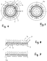
- the shape of the windows 11 depends on the position of the pockets 6 relative to one another within the stack of lamellas and the shape of the pockets 6. Since in the described embodiment the pockets 6 are at right angles to one another and the windows 11 are arranged between adjacent pockets 6, the described trapezoidal shape of the windows 11 is provided according to the invention.
- the Figures 6 and 7 show a stack of lamellas intended for an external rotor motor.
- the rotor 1 surrounds the stator 16. It has the grooves 17 for receiving the winding (s).
- the rotor 1 surrounds the stator 16 with the formation of an air gap.
- the rotor 1 and the stator 16 in turn each consist of a stack of lamellae.
- the stack of lamellas 2 of the rotor 1 is annular and has pockets 6 which are arranged uniformly distributed over the circumference and between each of which there is a window 11.
- eight pockets 6 for receiving the magnets are provided in the stack of lamellae 2.
- the pockets 6 are of the same design and each have a rectangular outline.
- the windows 11 have a trapezoidal shape, the radially inner longitudinal side 13 being shorter than the radially outer longitudinal side 12.
- the longitudinal side 13 is at a short distance from the run-up cage 4, which has the axially extending damper rods 8, which are evenly distributed over the circumference of the lamella stack 2.
- the run-up cage 4 is located on the inner circumferential surface of the lamella stack 2.
- the cavities of the lamella stack 2 formed by the windows 11 are closed at the end by at least one sheet-metal lamella 3a during the die-casting process ( Fig. 7 ).
- These end-side sheet metal lamellas 3 a are basically of the same design as the lamellae 3 which form the lamella stack 2. However, the end sheet metal lamellas 3a have no windows 11. If the end sheet metal lamellas 3a are attached to both ends of the lamella stack 2, the cavities 11 of the lamella stack 2 are closed.
- the run-up cage 4 can then be produced without problems using the die-casting process.
- the sheet metal lamellae 3a at the end prevent the die-cast material from entering the pockets 6 in the manner described.
- the Figures 8 and 9 show a comparative example, not belonging to the invention, in which a stack of lamellas is used in a linear motor.
- the stack of lamellae 2 of the rotor 1 has the pockets 6 for Hold the magnets.
- the pockets 6 are in a line with a distance behind one another.
- the windows 11, which form the cavities within the stack of lamellas 2, are located between the pockets 6. They have a rectangular outline and are each the same size.
- the windows 11 protrude over both sides of the pockets 6 and reach close to the damper rods 8, which are arranged along the straight edge of the rotor 11.
- the rotor 1 moves along the stator 16, which is also formed from a stack of lamellas and has the grooves 17 for receiving the winding (s).
- At least one sheet metal lamella 3a, in which the windows 11 are missing, is placed on both ends of the lamella stack 2.
- the cavities 11 of the stack of lamellae 2 are closed by the sheet metal lamellae 3a at the end during the die-casting process.
- the stack of lamellas can also be used for generators.
- Aluminum, aluminum alloys, copper, copper alloys and materials with a conductance of ⁇ 58 MS / m are advantageous as die-cast materials.
Landscapes
- Engineering & Computer Science (AREA)
- Power Engineering (AREA)
- Manufacturing & Machinery (AREA)
- Mechanical Engineering (AREA)
- Manufacture Of Motors, Generators (AREA)
- Permanent Field Magnets Of Synchronous Machinery (AREA)
- Iron Core Of Rotating Electric Machines (AREA)
Description
- Die Erfindung betrifft einen aus Blechlamellen gebildeten Lamellenstapel für Rotoren und/oder Statoren von Elektromotoren und Generatoren nach dem Oberbegriff des Anspruches 1 sowie einen Rotor nach Anspruch 4.
- Lamellenstapel werden für Rotoren und Statoren von Elektromotoren eingesetzt. Der Lamellenstapel besteht aus aufeinandergesetzten und miteinander verbundenen Blechlamellen. Wird der Lamellenstapel für Rotoren von Synchronmotoren eingesetzt, dann hat der Rotor als Anlaufhilfe einen Anlaufkäfig.
- Es ist ein aus Blechlamellen gebildeter Lamellenstapel bekannt (
DE 102 27 859 A1 ,JP S57 186 966 A - Es ist ein weiteres, aus aufeinander sitzenden Blechlamellen gebildetes Lamellenpaket bekannt (
JP 5-122877 A - Es ist weiter bekannt (
JP S61 102155 A - Es ist auch bekannt (
DE 886 337 C ), bei der Herstellung von Kurzschlusskäfigläufern die axial verlaufenden Hohlräume im Lamellenpaket während des Spritzgießverfahrens durch Blechscheiben zu verschließen. - Der Erfindung liegt die Aufgabe zugrunde, den gattungsgemäßen Lamellenstapel und den Rotor so auszubilden, dass sie kostengünstig und zuverlässig hergestellt werden können.
- Diese Aufgabe wird beim gattungsgemäßen Lamellenstapel erfindungsgemäß mit den kennzeichnenden Merkmalen des Anspruches 1 und beim Rotor mit den Merkmalen des Anspruches 4 gelöst.
- Beim erfindungsgemäßen Lamellenstapel sind zwischen benachbarten Taschen zur Aufnahme der Magnete axial verlaufende Hohlräume vorgesehen. Die Hohlräume reduzieren den Streufluss der Magnete wesentlich. Die Hohlräume sind im Lamellenstapel an beiden Enden geschlossen, wenn der Anlaufkäfig im Druckgießverfahren hergestellt wird. Die Hohlräume werden darum beim Druckgießverfahren nicht mit dem Druckgießmaterial gefüllt, obwohl sie nur geringen Abstand vom Anlaufkäfig haben. Der Abstand zwischen den Taschen und dem herzustellenden Anlaufkäfig ist wegen der geschlossenen Hohlräume so groß, dass beim Druckgießvorgang der Druck so weit abgebaut werden kann, dass das Druckgießmaterial nicht in die Taschen gelangt. Es ist dadurch möglich, erst nach dem Druckgießvorgang die Magnete in die Taschen des Lamellenstapels einzusetzen. Die Hohlräume haben kleineren radialen Abstand vom Anlaufkäfig als die Taschen für die Magnete.
- Die Hohlräume sind an beiden Enden durch jeweils wenigstens eine Blechlamelle geschlossen. Sie bildet jeweils eine endseitige Blechlamelle des Lamellenstapels.
- Die endseitigen Blechlamellen können aus magnetischem oder nichtmagnetischem Material bestehen.
- Als Druckgießmaterial wird vorteilhaft Aluminium, Aluminiumlegierungen, Kupfer, Kupferlegierungen und Materialien mit einem Leitwert ≥ 58 MS/m verwendet.
- Der erfindungsgemäße Rotor ist dadurch gekennzeichnet, dass er einen Lamellenstapel aufweist, bei dem zwischen benachbarten Taschen axial verlaufende Hohlräume vorhanden sind, die an beiden Enden geschlossen sind.
- Weitere Merkmale der Erfindung ergeben sich aus den weiteren Ansprüchen, der Beschreibung und den Zeichnungen.
- Die Erfindung wird anhand eines in den Zeichnungen dargestellten Ausführungsbeispieles näher erläutert. Es zeigen
- Fig. 1
- im Axialschnitt einen erfindungsgemäßen Lamellenstapel, der Teil eines Rotors eines Elektromotors in Form eines Innenläufers ist,
- Fig. 2
- eine Stirnansicht des Lamellenstapels gemäß
Fig. 1 ohne endseitige Blechlamellen, - Fig. 3
- den erfindungsgemäßen Lamellenstapel gemäß
Fig. 2 in Verbindung mit einem als Stator dienenden weiteren Lamellenstapel in Axialansicht, - Fig. 4
- eine Stirnansicht des Lamellenstapels gemäß
Fig. 1 , - Fig. 5
- in einer Darstellung entsprechend
Fig. 4 den Lamellenstapel ohne endseitige Blechlamellen, - Fig. 6
- eine Stirnansicht einer weiteren Ausführungsform eines erfindungsgemäßen Lamellenstapels, der Teile eines Rotors eines Elektromotors in Form eines Außenläufers ist,
- Fig. 7
- eine Stirnansicht des Lamellenstapels gemäß
Fig. 6 mit endseitigen Blechlamellen, - Fig. 8
- einen für einen Linearmotor vorgesehenen Lamellenstapel ohne endseitige Blechlamellen der nicht zur Erfindung gehört,
- Fig. 9
- den Lamellenstapel gemäß
Fig. 8 mit endseitigen Blechlamellen. -
Fig. 1 zeigt einen Rotor 1, der einen Lamellenstapel 2 aufweist. Er besteht aus einzelnen, aufeinandergesetzten Blechlamellen 3, die in bekannter Weise miteinander verbunden sind. - Der Lamellenstapel 2 wird von einem Anlaufkäfig 4 umgeben, der im Druckgießverfahren hergestellt wird. Der Anlaufkäfig 4 überragt den Lamellenstapel 2 axial an beiden Enden. Der Anlaufkäfig 4 ist am Umfang des Lamellenstapels 2 angeordnet, der einen zylindrischen Außenmantel aufweist.
- Im Lamellenstapel 2 sind Magnete 5 untergebracht, die sich in Taschen 6 des Lamellenstapels 2 befinden. Im Ausführungsbeispiel hat der Lamellenstapel 2 vier rechtwinklig zueinander liegende Taschen 6 für die Magnete 5. Je nach Ausbildung des Rotors 1 kann der Lamellenstapel 2 auch eine andere Zahl von Taschen 6 und damit von Magneten 5 haben, wobei die Taschen dann unter anderen Winkeln zueinander liegen können. Die Taschen 6 haben jeweils rechteckigen Umriss und sind gleich ausgebildet. Sämtliche Taschen 6 enden jeweils mit geringem Abstand vom Anlaufkäfig 4 bzw. der Mantelfläche des Lamellenstapels 2.
- Die einzelnen Blechlamellen 3 weisen Öffnungen 6a auf (
Fig. 5 ), die die Taschen 6 des Lamellenstapels 2 zur Aufnahme der Magnete 5 bilden. Jede Blechlamelle 3 hat eine zentrische kreisringförmige Öffnung 7. Die Öffnungen 7 bilden im Lamellenstapel 2 eine zylindrische Aufnahme für eine (nicht dargestellte) Rotorwelle, auf welcher der Lamellenstapel 2 drehfest sitzt. - Der Anlaufkäfig 4 hat axial verlaufende Dämpferstäbe 8, die längs des Umfangs des Rotors 1 mit Abstand gleichmäßig verteilt angeordnet sind. Nach dem Druckgießvorgang befinden sich an beiden Enden des Lamellenstapels 2 (nicht dargestellte) Kurzschlussringe, die sich jeweils in einem Aufnahmeraum 9, 10 befinden (
Fig. 1 ). - Damit die in den Taschen 6 befindlichen Magnete 5 keinen großen Streufluss erzeugen, befinden sich im Bereich zwischen den Taschen 6 Hohlräume 11, die den Streufluss wesentlich reduzieren. Die Hohlräume 11 haben etwa trapezförmigen Umriss mit einer Längsseite 12, die vorteilhaft parallel zur Innenseite des Anlaufkäfigs 4 verläuft. Die gegenüberliegende kürzere Längsseite 13 des Hohlraumes 11 liegt auf einer gedachten, die inneren Ecken der rechtwinklig zueinander liegenden benachbarten Taschen 6 verbindenden Ebene. Die Enden der beiden Längsseiten 12, 13 sind durch Schmalseiten 14, 15 miteinander verbunden, die jeweils parallel zu den Schmalseiten der jeweils benachbarten Tasche 6 verlaufen. Die längere Längsseite 12 der Hohlräume 11 hat geringeren Radialabstand vom Anlaufkäfig 4 als die radial äußeren Ecken der Taschen 6. Der Abstand der Hohlräume 11 von den Schmalseiten der benachbarten Taschen 6 ist wesentlich kleiner als der Radialabstand, den die Hohlräume 11 bzw. die Längsseiten 12 vom Anlaufkäfig 4 haben. Jede Blechlamelle 3 hat Öffnungen 11, die im Lamellenstapel 2 die axialen Hohlräume 11 bilden, die vorteilhaft gleich ausgebildet sind.
- Der Anlaufkäfig 4 wird im Druckgießverfahren kostengünstig hergestellt. Hierbei ist es vorteilhaft, wenn die Magnete 5 erst nach dem Druckgießvorgang in die Taschen 6 geschoben werden. Da beim Druckgießen ein hoher Druck angewendet wird, ist ein Abstand zwischen dem Anlaufkäfig 4 und den Taschen 6 von einigen Millimetern erforderlich. Die Hohlräume 11 würden beim Druckgießen mit dem Druckgießmaterial gefüllt. Wegen des geringen Abstandes zu den Taschen 6 könnte der Druck beim Druckgießvorgang wegen des geringen Abstandes zwischen den Hohlräumen 11 und den Taschen 6 nicht abgebaut werden. Dies hätte zur Folge, dass auch die Taschen 6 mit dem Druckgießmaterial gefüllt würden.
- Um den Anlaufkäfig 4 vorteilhafterweise im Druckgießverfahren herzustellen und andererseits den Streufluss der Magnete 5 durch Anbringen der Hohlräume 11 zu reduzieren, ist der Lamellenstapel 2 so ausgebildet, dass die Hohlräume 11 endseitig durch jeweils wenigstens eine Blechlamelle 3a abgedeckt werden. Diese Blechlamelle 3a (
Fig. 4 ) unterscheidet sich von allen anderen Blechlamellen 3 des Lamellenstapels 2 dadurch, dass sie keine Fenster aufweist. Wenn darum auf die beiden Stirnseiten des Lamellenstapels 2 jeweils eine solche Blechlamelle 3a aufgesetzt wird, sind die Hohlräume 11 geschlossen, so dass der Anlaufkäfig 4 problemlos im Druckgießverfahren hergestellt werden kann. Die endseitigen Blechlamellen 3a dienen als Deckel, die den Zutritt des Druckgießmaterials in die Hohlräume 11 verhindern. Der Abstand zwischen dem Anlaufkäfig 4 und den Taschen 6 ist wegen der abgedeckten Hohlräume 11 nunmehr so groß, dass der Druck beim Druckgießvorgang so weit abgebaut werden kann, dass das Druckgießmaterial nicht in die Taschen 6 gelangt. - Die beiden endseitigen Blechlamellen 3a können aus einem magnetischen oder einem nichtmagnetischen Werkstoff bestehen. Es ist ohne Weiteres möglich, an den beiden Enden des Lamellenstapels 2 jeweils auch mehr als nur eine Blechlamelle 3a vorzusehen.
- Die unterschiedlichen Blechlamellen 3 und 3a lassen sich sehr einfach aus einem Blechband stanzen. Das Stapeln der unterschiedlichen Blechlamellen 3 und 3a zum Lamellenstapel 2 erfolgt in bekannter Weise automatisch. Wie
Fig. 3 zeigt, ist der Rotor 1 von einem Stator 16 umgeben. Er besteht ebenfalls aus gestapelten Blechlamellen, die am inneren Rand mit Nuten 17 zur Aufnahme der Wicklung 18 versehen sind. Diese Ausbildung ist Teil eines permanentmagneterregten Synchronmotors mit den eingebetteten Magneten 5 und dem Anlaufkäfig 4. Ein solcher Synchronmotor ist für ein direktes Einschalten ins Netz geeignet. Er ist in der Lage, ohne Einsatz eines Umrichters selbstständig zu beschleunigen und zu synchronisieren. Nach dem asynchronen Hochlauf läuft der Synchronmotor synchron am Netz und hat einen hohen Wirkungsgrad. Der asynchrone Anlauf hat den Vorteil, dass ein Umrichter nicht erforderlich ist. Die Anordnung gemäßFig. 3 ist Teil eines Innenläufer-Synchronmotors. - Die Form der Fenster 11 hängt von der Lage der Taschen 6 relativ zueinander innerhalb des Lamellenstapels und der Form der Taschen 6 ab. Da bei der beschriebenen Ausführungsform die Taschen 6 rechtwinklig zueinander liegen und die Fenster 11 zwischen benachbarten Taschen 6 angeordnet sind, ist die beschriebene Trapezform der Fenster 11 erfindungsgemäß vorgesehen.
- Die
Fig. 6 und 7 zeigen einen Lamellenstapel, der für einen Außenläufermotor vorgesehen ist. In diesem Falle umgibt der Rotor 1 den Stator 16. Er hat die Nuten 17 zur Aufnahme der Wicklung(en). Der Rotor 1 umgibt den Stator 16 unter Bildung eines Luftspaltes. - Der Rotor 1 und der Stator 16 bestehen wiederum jeweils aus einem Lamellenstapel. Der Lamellenstapel 2 des Rotors 1 ist ringförmig ausgebildet und weist über den Umfang gleichmäßig verteilt angeordnete Taschen 6 auf, zwischen denen sich jeweils ein Fenster 11 befindet. Im Ausführungsbeispiel sind im Lamellenstapel 2 acht Taschen 6 zur Aufnahme der Magnete vorgesehen. Die Taschen 6 sind gleich ausgebildet und haben jeweils rechteckigen Umriss. Die Fenster 11 haben Trapezform, wobei die radial innere Längsseite 13 kürzer ist als die radial außen liegende Längsseite 12. Die Längsseite 13 hat geringen Abstand vom Anlaufkäfig 4, der die über den Umfang des Lamellenstapels 2 gleichmäßig verteilt angeordneten, axial verlaufenden Dämpferstäben 8 aufweist. Der Anlaufkäfig 4 befindet sich an der inneren Mantelfläche des Lamellenstapels 2.
- Damit beim Druckgießvorgang das Druckgießmaterial nicht in die Fenster 11 und von dort in die Taschen 6 gelangt, sind die durch die Fenster 11 gebildeten Hohlräume des Lamellenstapels 2 beim Druckgießvorgang endseitig durch jeweils wenigstens eine Blechlamelle 3a geschlossen (
Fig. 7 ). Diese endseitigen Blechlamellen 3a sind grundsätzlich gleich ausgebildet wie die Lamellen 3, die den Lamellenstapel 2 bilden. Die endseitigen Blechlamellen 3a haben jedoch keine Fenster 11. Werden die endseitigen Blechlamellen 3a an beiden Enden des Lamellenstapels 2 angebracht, werden die Hohlräume 11 des Lamellenstapels 2 geschlossen. Dann kann der Anlaufkäfig 4 problemlos im Druckgießverfahren hergestellt werden. Wie beim vorigen Ausführungsbeispiel verhindern die endseitigen Blechlamellen 3a in der beschriebenen Weise den Zutritt des Druckgießmaterials in die Taschen 6. - Die
Fig. 8 und 9 zeigen ein nicht zur Erfindung gehörendes Vergleichsbeispiel, bei dem ein Lamellenstapel bei einem Linearmotor eingesetzt wird. Der Lamellenstapel 2 des Läufers 1 hat die Taschen 6 zur Aufnahme der Magnete. Die Taschen 6 liegen in einer Linie mit Abstand hintereinander. Zwischen den Taschen 6 befinden sich die Fenster 11, die innerhalb des Lamellenstapels 2 die Hohlräume bilden. Sie haben rechteckigen Umriss und sind jeweils gleich groß. Die Fenster 11 ragen über beide Seiten der Taschen 6 vor und reichen bis nahe an die Dämpferstäbe 8, die längs des geraden Randes des Läufers 11 angeordnet sind. Der Läufer 1 bewegt sich längs des Stators 16, der ebenfalls aus einem Lamellenstapel gebildet wird und die Nuten 17 zur Aufnahme der Wicklung(en) aufweist. Damit beim Druckgießvorgang das Druckgießmaterial nicht in die Hohlräume 11 gelangt, wird auf beide Enden des Lamellenstapels 2 jeweils mindestens eine Blechlamelle 3a aufgelegt, bei der die Fenster 11 fehlen. Dadurch werden die Hohlräume 11 des Lamellenstapels 2 durch die endseitigen Blechlamellen 3a während des Druckgießvorganges geschlossen. - Der Lamellenstapel kann auch für Generatoren eingesetzt werden.
- Als Druckgießmaterial kommen vorteilhaft Aluminium, Aluminiumlegierungen, Kupfer, Kupferlegierungen und Materialien mit einem Leitwert von ≥ 58 MS/m in Betracht.
Claims (4)
- Aus Blechlamellen (3) gebildeter Lamellenstapel (2) für Rotoren und/oder Statoren von Elektromotoren und Generatoren, mit zur Aufnahme von Magneten (5) dienenden Taschen (6), die winklig zueinander verlaufen und rechteckigen Umriss haben, mit einem Anlaufkäfig (4), der im Druckgießverfahren hergestellt ist, am Umfang des Lamellenstapels (2) angeordnet ist und den Lamellenstapel (2) innen oder außen umschließt, und mit zwischen benachbarten Taschen (6) axial verlaufenden Hohlräumen (11), die kleineren radialen Abstand vom Anlaufkäfig (4) haben als die Taschen (6),
dadurch gekennzeichnet, dass die Hohlräume (11) an beiden Enden durch jeweils wenigstens eine endseitige Blechlamelle (3a) des Lamellenstapels (2) geschlossen sind und einen trapezförmigen Umriss haben. - Lamellenstapel (2) nach Anspruch 1,
dadurch gekennzeichnet, dass die Blechlamelle (3a) aus magnetischem oder nicht magnetischem Material besteht. - Lamellenstapel nach Anspruch 1 oder 2,
dadurch gekennzeichnet, dass das Druckgießmaterial des Druckgießverfahrens Aluminium, Aluminiumlegierungen, Kupfer, Kupferlegierungen oder Materialien mit einem Leitwert ≥ 58 MS/m ist. - Rotor mit einem Lamellenstapel nach einem der Ansprüche 1 bis 3.
Priority Applications (1)
| Application Number | Priority Date | Filing Date | Title |
|---|---|---|---|
| PL12007889T PL2597752T3 (pl) | 2011-11-28 | 2012-11-23 | Stos lameli do wirników i/lub stojanów silników elektrycznych i generatorów, wirnik z takim stosem lameli |
Applications Claiming Priority (1)
| Application Number | Priority Date | Filing Date | Title |
|---|---|---|---|
| DE102011119922A DE102011119922A1 (de) | 2011-11-28 | 2011-11-28 | Lamellenstapel für Rotoren und/oder Statoren von Elektromotoren und Generatoren,Rotor mit einem solchen Lamellenstapel sowie Verfahren zur Herstellung eines Rotors und/oder Stators |
Publications (3)
| Publication Number | Publication Date |
|---|---|
| EP2597752A2 EP2597752A2 (de) | 2013-05-29 |
| EP2597752A3 EP2597752A3 (de) | 2017-08-16 |
| EP2597752B1 true EP2597752B1 (de) | 2021-04-21 |
Family
ID=47594190
Family Applications (1)
| Application Number | Title | Priority Date | Filing Date |
|---|---|---|---|
| EP12007889.4A Active EP2597752B1 (de) | 2011-11-28 | 2012-11-23 | Lamellenstapel für Rotoren und/oder Statoren von Elektromotoren und Generatoren, Rotor mit einem solchen Lamellenstapel |
Country Status (5)
| Country | Link |
|---|---|
| EP (1) | EP2597752B1 (de) |
| DE (1) | DE102011119922A1 (de) |
| ES (1) | ES2881173T3 (de) |
| HU (1) | HUE056164T2 (de) |
| PL (1) | PL2597752T3 (de) |
Families Citing this family (3)
| Publication number | Priority date | Publication date | Assignee | Title |
|---|---|---|---|---|
| US20180205302A1 (en) * | 2017-01-19 | 2018-07-19 | Hamilton Sundstrand Corporation | Permanent magnet (pm) brushless machine with outer rotor |
| CN111106733B (zh) * | 2019-12-11 | 2022-04-01 | 南京理工大学 | 异步起动永磁同步直线电机及其控制方法 |
| EP4037153A1 (de) | 2021-02-02 | 2022-08-03 | Siemens Gamesa Renewable Energy A/S | Rotorkörper für eine permanentmagnetmaschine |
Citations (1)
| Publication number | Priority date | Publication date | Assignee | Title |
|---|---|---|---|---|
| JPS57186966A (en) * | 1981-05-11 | 1982-11-17 | Hitachi Ltd | Rotor for permanent-magnet type synchronous motor |
Family Cites Families (10)
| Publication number | Priority date | Publication date | Assignee | Title |
|---|---|---|---|---|
| DE886337C (de) * | 1944-01-14 | 1953-08-13 | Bosch Gmbh Robert | Verfahren zur Herstellung von Kurzschlusskaefiglaeufern, insbesondere fuer gekapselte Kaeltemaschinen |
| DE3150770A1 (de) * | 1981-12-22 | 1983-06-30 | Kienle & Spiess Stanz- und Druckgießwerk GmbH, 7123 Sachsenheim | Verfahren zur herstellung von aus blechteilen bestehenden paketen sowie vorrichtung zur durchfuehrung eines solchen verfahrens |
| JPS61102157A (ja) * | 1984-10-22 | 1986-05-20 | Mitsubishi Electric Corp | かご形回転子の製造方法 |
| JPS61102155A (ja) * | 1984-10-22 | 1986-05-20 | Mitsubishi Electric Corp | かご形回転子の製造方法 |
| JPH05122877A (ja) * | 1991-10-30 | 1993-05-18 | Matsushita Electric Ind Co Ltd | 永久磁石式同期電動機の回転子 |
| JP3676242B2 (ja) * | 2001-01-30 | 2005-07-27 | 三洋電機株式会社 | 誘導同期電動機 |
| JP2003009483A (ja) * | 2001-06-21 | 2003-01-10 | Sumitomo Heavy Ind Ltd | 永久磁石埋込み型誘導電動機 |
| JP2004096850A (ja) * | 2002-08-30 | 2004-03-25 | Toyo Electric Mfg Co Ltd | 誘導始動形同期回転電機の回転子 |
| DE10254967A1 (de) * | 2002-11-26 | 2004-06-09 | Danfoss Compressors Gmbh | Läufer eines Elektromotors |
| KR100531818B1 (ko) * | 2003-06-18 | 2005-11-30 | 엘지전자 주식회사 | 유도동기기의 회전자 구조 |
-
2011
- 2011-11-28 DE DE102011119922A patent/DE102011119922A1/de active Pending
-
2012
- 2012-11-23 PL PL12007889T patent/PL2597752T3/pl unknown
- 2012-11-23 HU HUE12007889A patent/HUE056164T2/hu unknown
- 2012-11-23 ES ES12007889T patent/ES2881173T3/es active Active
- 2012-11-23 EP EP12007889.4A patent/EP2597752B1/de active Active
Patent Citations (1)
| Publication number | Priority date | Publication date | Assignee | Title |
|---|---|---|---|---|
| JPS57186966A (en) * | 1981-05-11 | 1982-11-17 | Hitachi Ltd | Rotor for permanent-magnet type synchronous motor |
Also Published As
| Publication number | Publication date |
|---|---|
| DE102011119922A1 (de) | 2013-05-29 |
| PL2597752T3 (pl) | 2021-11-22 |
| ES2881173T3 (es) | 2021-11-29 |
| EP2597752A3 (de) | 2017-08-16 |
| HUE056164T2 (hu) | 2022-01-28 |
| EP2597752A2 (de) | 2013-05-29 |
Similar Documents
| Publication | Publication Date | Title |
|---|---|---|
| EP3669439B1 (de) | Rotor für eine elektrische maschine, insbesondere eines kraftfahrzeugs, sowie verfahren zum herstellen eines solchen rotors | |
| EP2975734B1 (de) | Anordnung zur statorkühlung eines elektrischen motors | |
| EP3593441B1 (de) | Elektromotor | |
| DE102008026648B4 (de) | Rotor für einen elektronisch kommutierten Elektromotor, Verfahren zur Herstellung eines solchen Rotors sowie bei der Herstellung eines solchen Rotors verwendbares Zwischenprodukt | |
| DE102014226047B4 (de) | Speichenrotor mit Umspritzung | |
| DE102004007322A1 (de) | Statoranordnung für eine elektrische Maschine | |
| DE112015002516B4 (de) | Elektrische Rotationsmaschine und Herstellungsverfahren für eine elektrische Rotationsmaschine | |
| DE102009045101A1 (de) | Elektrische Maschine mit minimiertem Rastmoment | |
| EP3520200B1 (de) | Elektrischer antriebsmotor | |
| DE112014007129T5 (de) | Statorkern für eine elektrische Rotationsmaschine, elektrische Rotationsmaschine und Verfahren zur Herstellung einer elektrischen Rotationsmaschine | |
| DE102015011863B4 (de) | Elektrische Maschine | |
| DE102014018223A1 (de) | Elektrische Maschine, insbesondere Asynchronmaschine | |
| DE102017223824A1 (de) | Elektrodrehmaschinenrotor | |
| DE112014001408T5 (de) | Rotoraufbau und elektrische Fluidpumpe | |
| DE102016120374A1 (de) | Ständer und bürstenloser Gleichstrommotor mit demselben | |
| EP3205004B1 (de) | Käfigläufer für eine elektrische asynchronmaschine mit einen kurzschlussring stabilisierender stützscheibe | |
| EP2549630B1 (de) | Kurzschlussläufer einer Asynchronmaschine und Verfahren zur Herstellung eines derartigen Läufers | |
| EP3610559B1 (de) | Elektrischer antriebsmotor | |
| EP2597752A2 (de) | Lamellenstapel für Rotoren und/oder Statoren von Elektromotoren und Generatoren, Rotor mit einem solchen Lamellenstapel sowie Verfahren zur Herstellung eines Rotors und/oder Stators | |
| EP3648309B1 (de) | Ec-motor für ein elektrisches handwerkzeug sowie verfahren zur herstellung eines rotors für einen ec-motor | |
| EP3154176B1 (de) | Elektrischer antriebsmotor | |
| EP3835531B1 (de) | Türantrieb mit einer leistungsstarken, kleinbauenden motoreinheit | |
| EP3391511B1 (de) | Läufer für eine permanentmagneterregte synchronmaschine, pollückenstab für einen solchen läufer und verfahren zum herstellen eines solchen läufers | |
| DE102015205334A1 (de) | Stator für eine Elektromaschine | |
| DE102021200809A1 (de) | Eine Rotorlamelle, ein Rotorblechpaket, ein Rotor und ein Verfahren zum Fertigen eines Rotors |
Legal Events
| Date | Code | Title | Description |
|---|---|---|---|
| PUAI | Public reference made under article 153(3) epc to a published international application that has entered the european phase |
Free format text: ORIGINAL CODE: 0009012 |
|
| AK | Designated contracting states |
Kind code of ref document: A2 Designated state(s): AL AT BE BG CH CY CZ DE DK EE ES FI FR GB GR HR HU IE IS IT LI LT LU LV MC MK MT NL NO PL PT RO RS SE SI SK SM TR |
|
| AX | Request for extension of the european patent |
Extension state: BA ME |
|
| PUAL | Search report despatched |
Free format text: ORIGINAL CODE: 0009013 |
|
| RIC1 | Information provided on ipc code assigned before grant |
Ipc: H02K 1/17 20060101ALI20170706BHEP Ipc: H02K 21/46 20060101ALI20170706BHEP Ipc: H02K 1/22 20060101AFI20170706BHEP Ipc: H02K 15/00 20060101ALI20170706BHEP Ipc: H02K 1/27 20060101ALI20170706BHEP Ipc: B22D 19/00 20060101ALI20170706BHEP |
|
| AK | Designated contracting states |
Kind code of ref document: A3 Designated state(s): AL AT BE BG CH CY CZ DE DK EE ES FI FR GB GR HR HU IE IS IT LI LT LU LV MC MK MT NL NO PL PT RO RS SE SI SK SM TR |
|
| AX | Request for extension of the european patent |
Extension state: BA ME |
|
| STAA | Information on the status of an ep patent application or granted ep patent |
Free format text: STATUS: REQUEST FOR EXAMINATION WAS MADE |
|
| 17P | Request for examination filed |
Effective date: 20180216 |
|
| RBV | Designated contracting states (corrected) |
Designated state(s): AL AT BE BG CH CY CZ DE DK EE ES FI FR GB GR HR HU IE IS IT LI LT LU LV MC MK MT NL NO PL PT RO RS SE SI SK SM TR |
|
| STAA | Information on the status of an ep patent application or granted ep patent |
Free format text: STATUS: EXAMINATION IS IN PROGRESS |
|
| 17Q | First examination report despatched |
Effective date: 20180503 |
|
| GRAP | Despatch of communication of intention to grant a patent |
Free format text: ORIGINAL CODE: EPIDOSNIGR1 |
|
| STAA | Information on the status of an ep patent application or granted ep patent |
Free format text: STATUS: GRANT OF PATENT IS INTENDED |
|
| INTG | Intention to grant announced |
Effective date: 20201106 |
|
| GRAS | Grant fee paid |
Free format text: ORIGINAL CODE: EPIDOSNIGR3 |
|
| GRAA | (expected) grant |
Free format text: ORIGINAL CODE: 0009210 |
|
| STAA | Information on the status of an ep patent application or granted ep patent |
Free format text: STATUS: THE PATENT HAS BEEN GRANTED |
|
| AK | Designated contracting states |
Kind code of ref document: B1 Designated state(s): AL AT BE BG CH CY CZ DE DK EE ES FI FR GB GR HR HU IE IS IT LI LT LU LV MC MK MT NL NO PL PT RO RS SE SI SK SM TR |
|
| REG | Reference to a national code |
Ref country code: GB Ref legal event code: FG4D Free format text: NOT ENGLISH |
|
| REG | Reference to a national code |
Ref country code: CH Ref legal event code: EP |
|
| REG | Reference to a national code |
Ref country code: DE Ref legal event code: R096 Ref document number: 502012016730 Country of ref document: DE Ref country code: IE Ref legal event code: FG4D Free format text: LANGUAGE OF EP DOCUMENT: GERMAN |
|
| REG | Reference to a national code |
Ref country code: AT Ref legal event code: REF Ref document number: 1385671 Country of ref document: AT Kind code of ref document: T Effective date: 20210515 |
|
| REG | Reference to a national code |
Ref country code: LT Ref legal event code: MG9D |
|
| REG | Reference to a national code |
Ref country code: NL Ref legal event code: MP Effective date: 20210421 |
|
| REG | Reference to a national code |
Ref country code: SK Ref legal event code: T3 Ref document number: E 37965 Country of ref document: SK |
|
| PG25 | Lapsed in a contracting state [announced via postgrant information from national office to epo] |
Ref country code: FI Free format text: LAPSE BECAUSE OF FAILURE TO SUBMIT A TRANSLATION OF THE DESCRIPTION OR TO PAY THE FEE WITHIN THE PRESCRIBED TIME-LIMIT Effective date: 20210421 Ref country code: LT Free format text: LAPSE BECAUSE OF FAILURE TO SUBMIT A TRANSLATION OF THE DESCRIPTION OR TO PAY THE FEE WITHIN THE PRESCRIBED TIME-LIMIT Effective date: 20210421 Ref country code: NL Free format text: LAPSE BECAUSE OF FAILURE TO SUBMIT A TRANSLATION OF THE DESCRIPTION OR TO PAY THE FEE WITHIN THE PRESCRIBED TIME-LIMIT Effective date: 20210421 Ref country code: BG Free format text: LAPSE BECAUSE OF FAILURE TO SUBMIT A TRANSLATION OF THE DESCRIPTION OR TO PAY THE FEE WITHIN THE PRESCRIBED TIME-LIMIT Effective date: 20210721 Ref country code: HR Free format text: LAPSE BECAUSE OF FAILURE TO SUBMIT A TRANSLATION OF THE DESCRIPTION OR TO PAY THE FEE WITHIN THE PRESCRIBED TIME-LIMIT Effective date: 20210421 |
|
| REG | Reference to a national code |
Ref country code: ES Ref legal event code: FG2A Ref document number: 2881173 Country of ref document: ES Kind code of ref document: T3 Effective date: 20211129 |
|
| PG25 | Lapsed in a contracting state [announced via postgrant information from national office to epo] |
Ref country code: RS Free format text: LAPSE BECAUSE OF FAILURE TO SUBMIT A TRANSLATION OF THE DESCRIPTION OR TO PAY THE FEE WITHIN THE PRESCRIBED TIME-LIMIT Effective date: 20210421 Ref country code: SE Free format text: LAPSE BECAUSE OF FAILURE TO SUBMIT A TRANSLATION OF THE DESCRIPTION OR TO PAY THE FEE WITHIN THE PRESCRIBED TIME-LIMIT Effective date: 20210421 Ref country code: GR Free format text: LAPSE BECAUSE OF FAILURE TO SUBMIT A TRANSLATION OF THE DESCRIPTION OR TO PAY THE FEE WITHIN THE PRESCRIBED TIME-LIMIT Effective date: 20210722 Ref country code: LV Free format text: LAPSE BECAUSE OF FAILURE TO SUBMIT A TRANSLATION OF THE DESCRIPTION OR TO PAY THE FEE WITHIN THE PRESCRIBED TIME-LIMIT Effective date: 20210421 Ref country code: IS Free format text: LAPSE BECAUSE OF FAILURE TO SUBMIT A TRANSLATION OF THE DESCRIPTION OR TO PAY THE FEE WITHIN THE PRESCRIBED TIME-LIMIT Effective date: 20210821 Ref country code: PT Free format text: LAPSE BECAUSE OF FAILURE TO SUBMIT A TRANSLATION OF THE DESCRIPTION OR TO PAY THE FEE WITHIN THE PRESCRIBED TIME-LIMIT Effective date: 20210823 Ref country code: NO Free format text: LAPSE BECAUSE OF FAILURE TO SUBMIT A TRANSLATION OF THE DESCRIPTION OR TO PAY THE FEE WITHIN THE PRESCRIBED TIME-LIMIT Effective date: 20210721 |
|
| REG | Reference to a national code |
Ref country code: DE Ref legal event code: R097 Ref document number: 502012016730 Country of ref document: DE |
|
| REG | Reference to a national code |
Ref country code: HU Ref legal event code: AG4A Ref document number: E056164 Country of ref document: HU |
|
| PG25 | Lapsed in a contracting state [announced via postgrant information from national office to epo] |
Ref country code: EE Free format text: LAPSE BECAUSE OF FAILURE TO SUBMIT A TRANSLATION OF THE DESCRIPTION OR TO PAY THE FEE WITHIN THE PRESCRIBED TIME-LIMIT Effective date: 20210421 Ref country code: CZ Free format text: LAPSE BECAUSE OF FAILURE TO SUBMIT A TRANSLATION OF THE DESCRIPTION OR TO PAY THE FEE WITHIN THE PRESCRIBED TIME-LIMIT Effective date: 20210421 Ref country code: DK Free format text: LAPSE BECAUSE OF FAILURE TO SUBMIT A TRANSLATION OF THE DESCRIPTION OR TO PAY THE FEE WITHIN THE PRESCRIBED TIME-LIMIT Effective date: 20210421 Ref country code: SM Free format text: LAPSE BECAUSE OF FAILURE TO SUBMIT A TRANSLATION OF THE DESCRIPTION OR TO PAY THE FEE WITHIN THE PRESCRIBED TIME-LIMIT Effective date: 20210421 Ref country code: RO Free format text: LAPSE BECAUSE OF FAILURE TO SUBMIT A TRANSLATION OF THE DESCRIPTION OR TO PAY THE FEE WITHIN THE PRESCRIBED TIME-LIMIT Effective date: 20210421 |
|
| PLBE | No opposition filed within time limit |
Free format text: ORIGINAL CODE: 0009261 |
|
| STAA | Information on the status of an ep patent application or granted ep patent |
Free format text: STATUS: NO OPPOSITION FILED WITHIN TIME LIMIT |
|
| 26N | No opposition filed |
Effective date: 20220124 |
|
| PG25 | Lapsed in a contracting state [announced via postgrant information from national office to epo] |
Ref country code: IS Free format text: LAPSE BECAUSE OF FAILURE TO SUBMIT A TRANSLATION OF THE DESCRIPTION OR TO PAY THE FEE WITHIN THE PRESCRIBED TIME-LIMIT Effective date: 20210821 Ref country code: AL Free format text: LAPSE BECAUSE OF FAILURE TO SUBMIT A TRANSLATION OF THE DESCRIPTION OR TO PAY THE FEE WITHIN THE PRESCRIBED TIME-LIMIT Effective date: 20210421 |
|
| PG25 | Lapsed in a contracting state [announced via postgrant information from national office to epo] |
Ref country code: MC Free format text: LAPSE BECAUSE OF FAILURE TO SUBMIT A TRANSLATION OF THE DESCRIPTION OR TO PAY THE FEE WITHIN THE PRESCRIBED TIME-LIMIT Effective date: 20210421 |
|
| PG25 | Lapsed in a contracting state [announced via postgrant information from national office to epo] |
Ref country code: LU Free format text: LAPSE BECAUSE OF NON-PAYMENT OF DUE FEES Effective date: 20211123 Ref country code: BE Free format text: LAPSE BECAUSE OF NON-PAYMENT OF DUE FEES Effective date: 20211130 |
|
| REG | Reference to a national code |
Ref country code: BE Ref legal event code: MM Effective date: 20211130 |
|
| PG25 | Lapsed in a contracting state [announced via postgrant information from national office to epo] |
Ref country code: IE Free format text: LAPSE BECAUSE OF NON-PAYMENT OF DUE FEES Effective date: 20211123 |
|
| PG25 | Lapsed in a contracting state [announced via postgrant information from national office to epo] |
Ref country code: CY Free format text: LAPSE BECAUSE OF FAILURE TO SUBMIT A TRANSLATION OF THE DESCRIPTION OR TO PAY THE FEE WITHIN THE PRESCRIBED TIME-LIMIT Effective date: 20210421 |
|
| P01 | Opt-out of the competence of the unified patent court (upc) registered |
Effective date: 20230824 |
|
| REG | Reference to a national code |
Ref country code: DE Ref legal event code: R081 Ref document number: 502012016730 Country of ref document: DE Owner name: FEINTOOL INTERNATIONAL HOLDING AG, CH Free format text: FORMER OWNER: KIENLE + SPIESS GMBH, 74343 SACHSENHEIM, DE |
|
| REG | Reference to a national code |
Ref country code: AT Ref legal event code: PC Ref document number: 1385671 Country of ref document: AT Kind code of ref document: T Owner name: FEINTOOL INTERNATIONAL HOLDING AG, CH Effective date: 20240122 |
|
| REG | Reference to a national code |
Ref country code: HU Ref legal event code: GB9C Owner name: FEINTOOL INTERNATIONAL HOLDING AG, CH Free format text: FORMER OWNER(S): KIENLE + SPIESS GMBH, DE Ref country code: HU Ref legal event code: FH1C Free format text: FORMER REPRESENTATIVE(S): GOEDOELLE, KEKES, MESZAROS & SZABO SZABADALMI ES VEDJEGY IRODA, HU Representative=s name: GOEDOELLE, KEKES, MESZAROS & SZABO SZABADALMI ES VEDJEGY IRODA, HU |
|
| PG25 | Lapsed in a contracting state [announced via postgrant information from national office to epo] |
Ref country code: MK Free format text: LAPSE BECAUSE OF FAILURE TO SUBMIT A TRANSLATION OF THE DESCRIPTION OR TO PAY THE FEE WITHIN THE PRESCRIBED TIME-LIMIT Effective date: 20210421 |
|
| PG25 | Lapsed in a contracting state [announced via postgrant information from national office to epo] |
Ref country code: MT Free format text: LAPSE BECAUSE OF FAILURE TO SUBMIT A TRANSLATION OF THE DESCRIPTION OR TO PAY THE FEE WITHIN THE PRESCRIBED TIME-LIMIT Effective date: 20210421 |
|
| REG | Reference to a national code |
Ref country code: ES Ref legal event code: PC2A Owner name: FEINTOOL SYSTEM PARTS SACHSENHEIM GMBH Effective date: 20241031 |
|
| REG | Reference to a national code |
Ref country code: ES Ref legal event code: PC2A Owner name: FEINTOOL INTERNATIONAL HOLDING AG Effective date: 20241105 |
|
| PGFP | Annual fee paid to national office [announced via postgrant information from national office to epo] |
Ref country code: PL Payment date: 20250922 Year of fee payment: 14 |
|
| REG | Reference to a national code |
Ref country code: CH Ref legal event code: U11 Free format text: ST27 STATUS EVENT CODE: U-0-0-U10-U11 (AS PROVIDED BY THE NATIONAL OFFICE) Effective date: 20251201 |
|
| PGFP | Annual fee paid to national office [announced via postgrant information from national office to epo] |
Ref country code: GB Payment date: 20251103 Year of fee payment: 14 |
|
| PGFP | Annual fee paid to national office [announced via postgrant information from national office to epo] |
Ref country code: AT Payment date: 20251114 Year of fee payment: 14 |
|
| PGFP | Annual fee paid to national office [announced via postgrant information from national office to epo] |
Ref country code: IT Payment date: 20251103 Year of fee payment: 14 |
|
| PGFP | Annual fee paid to national office [announced via postgrant information from national office to epo] |
Ref country code: HU Payment date: 20251204 Year of fee payment: 14 Ref country code: FR Payment date: 20251103 Year of fee payment: 14 |
|
| PGFP | Annual fee paid to national office [announced via postgrant information from national office to epo] |
Ref country code: TR Payment date: 20251014 Year of fee payment: 14 |
|
| PGFP | Annual fee paid to national office [announced via postgrant information from national office to epo] |
Ref country code: CH Payment date: 20251201 Year of fee payment: 14 |
|
| PGFP | Annual fee paid to national office [announced via postgrant information from national office to epo] |
Ref country code: SK Payment date: 20251128 Year of fee payment: 14 |
|
| PGFP | Annual fee paid to national office [announced via postgrant information from national office to epo] |
Ref country code: ES Payment date: 20251203 Year of fee payment: 14 |
|
| PGFP | Annual fee paid to national office [announced via postgrant information from national office to epo] |
Ref country code: DE Payment date: 20260128 Year of fee payment: 14 |