EP2597630A2 - Signalgerät mit einer Tonsignaleinheit und mit einer Lichtsignaleinheit - Google Patents
Signalgerät mit einer Tonsignaleinheit und mit einer Lichtsignaleinheit Download PDFInfo
- Publication number
- EP2597630A2 EP2597630A2 EP20120193868 EP12193868A EP2597630A2 EP 2597630 A2 EP2597630 A2 EP 2597630A2 EP 20120193868 EP20120193868 EP 20120193868 EP 12193868 A EP12193868 A EP 12193868A EP 2597630 A2 EP2597630 A2 EP 2597630A2
- Authority
- EP
- European Patent Office
- Prior art keywords
- signal
- hood
- light
- housing
- base body
- Prior art date
- Legal status (The legal status is an assumption and is not a legal conclusion. Google has not performed a legal analysis and makes no representation as to the accuracy of the status listed.)
- Granted
Links
Images

Classifications
-
- G—PHYSICS
- G08—SIGNALLING
- G08B—SIGNALLING SYSTEMS, e.g. PERSONAL CALLING SYSTEMS; ORDER TELEGRAPHS; ALARM SYSTEMS
- G08B7/00—Signalling systems according to two or more of groups G08B3/00 - G08B6/00
- G08B7/06—Signalling systems according to two or more of groups G08B3/00 - G08B6/00 using electric transmission, e.g. involving audible and visible signalling through the use of sound and light sources
-
- G—PHYSICS
- G08—SIGNALLING
- G08B—SIGNALLING SYSTEMS, e.g. PERSONAL CALLING SYSTEMS; ORDER TELEGRAPHS; ALARM SYSTEMS
- G08B5/00—Visible signalling systems, e.g. visible personal calling systems or remote indication of seats occupied
- G08B5/22—Visible signalling systems, e.g. visible personal calling systems or remote indication of seats occupied using electric transmission; using electromagnetic transmission
- G08B5/36—Visible signalling systems, e.g. visible personal calling systems or remote indication of seats occupied using electric transmission; using electromagnetic transmission using visible light sources
Definitions
- the present invention relates to a signal device with a sound signal unit for emitting an acoustic signal and with a light signal unit for emitting a visual signal, wherein a housing base is provided, with which the signal device is preferably arranged on a receiving body and wherein an upper housing part is provided, for forming a receiving space is arranged on the housing base body.
- Signaling devices with a sound signal unit for emitting an acoustic signal and with a light signal unit for emitting a visual signal are generally known. Furthermore, such signaling devices are known, which are arranged on electrical appliances, machinery or industrial production facilities. By the signaling devices, for example, warnings can be audibly or visually output.
- signal devices are prescribed which emit a visually perceptible light signal in addition to an acoustic sound signal.
- signaling devices are provided which comprise both the sound signal unit and the light signal unit in a structural unit.
- signal devices with a sound signal unit and a light signal unit are complex, and the assembly of such signal devices is often difficult.
- the signal devices can be arranged either in a flush or in a surface mounting on a wall, and the production of the electrical connections must often be done with increased expenditure of time.
- the sound signal unit and the light signal unit are to be separately mounted and electrically connected Units executed on the signal device, which can often be mounted by a fitter only after installation of the housing body on the receiving body, such as a wall.
- the housing upper part can be placed on the housing body and connected to this.
- the upper housing part usually forms a cover to form a closed receiving space in the signaling device.
- the invention includes the technical teaching that a main body of the light signal unit is formed from a light-transparent signal hood, wherein the signal hood has a base surface with which the signal hood is arranged on the housing base body.
- a housing main body can be provided with an upper housing part having only the Tonsignalü, and the light signal unit has a (separate) base body, which is formed by the signal hood itself. Consequently, the light signal unit does not have to be formed from a basic body, on which only after a signal hood is placed over which the visual signal is emitted.
- the only visible component of the light signal unit is the signal hood. Rather, the light signal unit according to the invention is characterized by a smaller number of components, which can also be easily connected to the housing base body of the signal device.
- the term "light-transparent" signal hood is to be understood in the present context that the signal hood for the passage of light emitted by a light source in the interior of the light signal unit light is formed from the inside to the outside.
- the signal hood does not necessarily have to be transparent, i. transparent, be formed, but rather can also be colored.
- the housing base body of the signaling device has a side wall, and the signal hood is placed with the base outside of the side wall and in particular connected by connecting means with the side wall.
- the signal hood radiating the light signal is arranged in direct contact with the side wall on the housing base body.
- the main body of the light signal unit denotes the body on which substantially all relevant components of the light signal unit are arranged.
- the light signal unit with the signal hood and the additional components can be regarded as ready for operation insofar as only electrical connections are led out of the main body of the light signal unit, which for example only have to be connected to a power supply and / or to a signal supply.
- a light signal unit is created with the main body and to be arranged on the main body operational essential components as a self-contained and functional unit, which must be subsequently arranged only on the housing body of the signal device and electrically connected.
- the base of the signal hood is spanned by a terminal frame, and the light signal unit has an electrical switching unit, which in the Area of the lead frame is arranged.
- the electrical switching unit which serves as an essential, functionally necessary unit for operating the light signal unit, connected directly to the signal hood before the signal hood itself is arranged on the side wall of the housing body. From the electrical switching unit, the electrical connection can be led out, which is electrically connected to other components in the housing body of the signal device.
- the base area of the signal hood, which is spanned by the leadframe does not have to extend in one plane in the present understanding of the base area, and the leadframe may, for example, deviate from a plane in that the leadframe has steps, steps, edges and the like.
- the invention provides that the terminal frame of the signal hood serves to set up the signal hood on the side wall of the housing base body, the joining surface between the side wall and the signal hood need not lie in a plane and the base of the signal hood can be adapted to the surface of the side wall.
- the base area of the signal hood can be slightly smaller than the area of the side wall. If the signal hood is placed on the side wall of the housing base body, then the electrical switching unit is already arranged in the arranged state on the signal hood, so that the light signal unit can be arranged essentially ready for operation on the side wall of the housing main body.
- the side wall of the housing base body may have an opening into which the electrical switching unit extends at least partially when the light signal unit is arranged on the side wall.
- the electrical switching unit may be formed by a carrier board, are arranged on the electronic components.
- the carrier board may be located in the footprint of the leadframe or parallel to the footprint of the leadframe, and the carrier board, but also components disposed on the carrier board, may extend into the opening in the side wall of the housing base.
- the opening can be made rectangular, for example, and the opening may have smaller dimensions than the side wall of the housing body. Circulating At the edge of the opening in the housing base body of the lead frame can be placed so that the opening in the housing base is closed by the lead frame and thus by the signal cover.
- the carrier board which forms the electrical switching unit can be held in the terminal frame of the signal hood with connecting means.
- the carrier board can be screwed into the signal hood, and the carrier board can have smaller dimensions than the terminal frame of the signal hood. If the carrier board is arranged on the inside in the signal hood, for example parallel to or in the base area of the signal hood itself, the signal hood can then be arranged covering the opening in the side wall on the side wall.
- the light signal unit has a lighting means, which is arranged in particular on the electrical switching unit and projects into the signal hood.
- the electrical switching unit embodied as a carrier board
- the luminous means for example a flash lamp
- the carrier board is arranged approximately in the region of the leadframe in the signal hood, the bulbs are located in the desired position within the signal hood after the switching unit is arranged in the signal hood.
- the signal hood can be designed in the form of a pyramid with a rectangular base, and the light source is located in the center of the pyramidal signal hood.
- the size of the pyramid is designed so that the base of the pyramid covers the opening in the side wall.
- a sealing cord can be arranged, which is introduced in particular circumferentially in the preferably rectangular running lead frame. If the signal hood is arranged with its connection frame over the opening on the side wall, the sealing cord seals the opening in the side wall, in particular if the signal hood is designed to be closed. This prevents that moisture and / or impurities can penetrate into the receiving space in the housing base body or in the interior of the signal hood.
- a line connection means is received in the housing base body, wherein the electrical switching unit has an electrical connection to the line connection means.
- the electrical connection between the electrical switching unit and the line connection means can be passed through the opening in the side wall of the housing base body, on which the signal hood is placed.
- the electrical switching unit may be arranged in the opening itself when the signal hood is arranged with the electrical switching unit on the side wall.
- the electrical connection between the switching unit and the line connection means can already be made by an installer prior to installation of the signal device, and the line connection means is used in particular to establish an electrical connection between the signal device and another circuit technology for wiring the signal device.
- An electrical line can be passed through housing breakthroughs that can be introduced into the housing body.
- the signaling device can in the manner described have an electrical switching unit for connecting the lighting means of the light signal unit, and the electrical switching unit is part of the light signal unit.
- an electrical assembly for generating sound may be provided in the housing base body, which is arranged with particular advantage on the inside in the housing upper part or held on this.
- a contact means with a first plug contact partner and a second plug contact partner can be arranged between the electrical assembly and the line connection means, and the first plug contact partner is located on the line connection means and the second plug contact partner is located on the electrical assembly for sound generation. If the upper housing part is arranged on the housing base body, then the contact means is produced by plugging together the plug-in contact partners.
- the Gescousegroundköper may for example have a depth of 40mm to 150mm, preferably from 45mm to 140mm and more preferably from 47mm to 125mm.
- the upper housing part may have a depth of 20mm to 75mm, preferably from 30mm to 60mm and more preferably from 32.5mm to 56mm.
- the housing upper part protrude in the assembled state on the housing base in the housing base body, so that the entire depth of the signal device does not necessarily result from the sum of the depths of the Gescousegroundgroper and the upper housing part.
- the result is a ratio of the depth of the Gescousegrundgropers to the upper housing part of 1.0 to 4.4, preferably from 1.4 to 4.1 and more preferably from 1.45 to 3.0.
- the light-emitting surface area of the signal hood can be from 60 cm 2 to 1000 cm 2 , preferably from 100 cm 2 to 500 cm 2 and particularly preferably from 154 cm 2 to 420 cm 2 .
- the surface area of the base area can be 40 cm 2 to 500 cm 2 , preferably from 80 cm 2 to 300 cm 2 and particularly preferably from 94 cm 2 to 242 cm 2 .
- the light-emitting surface area encompasses the entire surface of the signal hood, through which light can be emitted or transmitted to the outside.
- the signal hood for example, pyramid-shaped
- these are the four side surfaces of the pyramidal body.
- the envelope surface is to be considered and not the surface of the outer sides of the signal hood, which can be much larger in the case of structured surfaces.
- This embodiment ensures that a relatively large light-radiating surface area of the signal hood is provided, which results in a significantly improved heat dissipation.
- Leuchtmitel such as a flash lamp
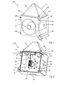
- FIG. 1 shows in a perspective view of a signaling device 100 according to the present invention.
- the signal device 100 has a sound signal unit 10, which is represented by a horn. Furthermore, the signal device 100 has a light signal unit 11, which is attached to a housing base body 12 of the signal device 100.
- connecting means 25 are provided in the form of screws, with which the light signal unit 11 is screwed onto a side wall 16 of the housing base body 12.
- the light signal unit 11 has a main body, which is designed as a signal hood 15.
- the signal hood 15 serves as the signal light radiating element, and in the signal hood 15, a light source can be introduced, through which the light signal is generated, but the signal hood 15 can also form the light itself, for example, when the signal hood 15 is designed as a surface radiator.
- the housing base body 12 is closed by a housing upper part 13, and the audio signal unit 10 is arranged on the inside of the housing upper part 13.
- the upper housing part 13 can be connected by locking pins 26 with the housing base body 12.
- the locking pins 26 may be designed so that they are arranged self-holding on the upper housing part 13, and if the upper housing part 13 is handled individually, a fitter 26 must not handle the locking pins also individually.
- the locking pins 26 can be locked in openings 27 which are introduced on the front of the housing base body 12, see FIG. 2 ,
- housing base body 12 holes 28 which are formed in the outside of the housing base body 12 integrally formed mounting tabs 29. Through the holes 28 fastening means can be passed to arrange the signal device 100 with the housing base 12 on a receiving body.
- the depth of the housing base body 12 is indicated by T G and the depth of the upper housing part 13 is indicated by T O , wherein the depth T O of the housing upper part 13 may be greater than shown in the illustration, because the upper housing part 13 may be part of its depth T. O protrude into the housing base 12.
- FIG. 2 shows the signal device 100 in an open mold by the housing upper part 13 is removed.
- the receiving space 14 is shown in the housing base body 12, and the housing base body 12 is through a housing bottom 30 and four laterally on the rectangular housing bottom 30 vertically extending side walls 16 are formed.
- hollow chambers 31 are formed on the side walls on the outside, in which the openings 27 for locking the locking pins 26 are placed on the front side.
- the side wall 16 arranged at the top has an opening 19, and the light signal unit 11 with the signal hood 15 is arranged on the upper side wall 16.
- an electrical switching unit 18 is inserted, which projects through an opening 19 in the side wall 16 into the receiving space 14 of the housing base body 12 partially.
- an electrical connection 22 with a line connection means 21 is shown, and to the line connection means 21 electrical lines can be connected, which are passed through at least one housing wall 16 through corresponding housing openings 32.
- the perspective view shows the signal hood 15 with a connection frame 17, with which the signal hood 15 is externally placed on the side wall 16 of the housing base body 12.
- the terminal frame 17 forms a rectangular base of the pyramidal signal hood 15, and the electrical switching unit 18 is formed by a carrier board which extends approximately in the plane of the lead frame 17.
- FIG. 3 shows a perspective view of the housing base body 12 with the line connection means 21, which is arranged on the housing bottom 30.
- a side wall 16 of the housing base body 12 has the opening 19, which has an approximately rectangular shape.
- the electrical connection 22 provided between the line connection means 21 and the light signal unit 11, which light signal unit 11 in the following FIG. 4 is shown in more detail.
- FIG. 4 shows a perspective view of the light signal unit 11.
- the main body of the light signal unit 11 is formed by a signal cap 15 having a pyramidal shape.
- the base of the pyramid is spanned by a lead frame 17, wherein the signal cap 15 is made of a light transparent material.
- an electrical switching unit 18 is inserted and connected by connecting means 24 to the signal hood 15.
- a lighting means 20 for example a flash lamp, which projects through the arrangement of the electrical switching unit 18 in the connection frame 17 of the signal hood 15 in the signal hood 15. If the light source 20 is put into operation, the emitted light can pass through the signal hood 15 and be visually perceived.
- a sealing cord 23 is introduced, which has a closed contour to seal the outside of the side wall 16, the opening 19 by placing the signal cap 15, see FIG. 3 ,
- the signal hood 15 may be provided, in the bottom side of which the electrical switching unit 18 is arranged and is screwed with connecting means 24, for example in the form of screws. Subsequently, the light signal unit 11 can be placed on the outside on the side wall 16 of the housing base body 12, and connecting means 25 (see FIG. 1 ) can be passed through connecting means receptacles 33 to subsequently connect the signal cap 15 with the base body 12.
- the light-emitting surface area of the signal hood 15 is indicated by A H
- the surface area of the base area is indicated by A G.
Landscapes
- Physics & Mathematics (AREA)
- General Physics & Mathematics (AREA)
- Arrangement Of Elements, Cooling, Sealing, Or The Like Of Lighting Devices (AREA)
- Non-Portable Lighting Devices Or Systems Thereof (AREA)
- Optical Communication System (AREA)
Abstract
Description
- Die vorliegende Erfindung betrifft ein Signalgerät mit einer Tonsignaleinheit zur Aussendung eines akustischen Signals und mit einer Lichtsignaleinheit zur Aussendung eines visuellen Signals, wobei ein Gehäusegrundkörper vorgesehen ist, mit dem das Signalgerät vorzugsweise auf einem Aufnahmekörper anordbar ist und wobei ein Gehäuseoberteil vorgesehen ist, das zur Bildung eines Aufnahmeraums am Gehäusegrundkörper angeordnet ist.
- Allgemein bekannt sind Signalgeräte mit einer Tonsignaleinheit zur Aussendung eines akustischen Signals und mit einer Lichtsignaleinheit zur Aussendung eines visuellen Signals, die beispielsweise Bestandteil einer Gebäudesicherheitseinrichtung sein können. Ferner sind derartige Signalgeräte bekannt, die an elektrischen Geräten, Maschinen oder industriellen Produktionseinrichtungen angeordnet werden. Durch die Signalgeräte können beispielsweise Warnungen akustisch oder visuell ausgegeben werden. Insbesondere in einer Installationsumgebung des Signalgerätes, in der ein hoher Geräuschpegel vorherrscht, sind Signalgeräte vorgeschrieben, die zusätzlich zu einem akustischen Tonsignal ein visuell wahrnehmbares Lichtsignal aussenden. Hierfür werden Signalgeräte vorgesehen, die in einer baulichen Einheit sowohl die Tonsignaleinheit als auch die Lichtsignaleinheit umfassen.
- Nachteilhafterweise sind Signalgeräte mit einer Tonsignaleinheit und einer Lichtsignaleinheit aufwändig aufgebaut, und die Montage solcher Signalgeräte ist häufig erschwert. Werden derartige Signalgeräte als Bestandteil der Sicherheitseinrichtungen in einem Gebäude verwendet, so können die Signalgeräte entweder in einer Unterputz- oder in einer Aufputzmontage an einer Wand angeordnet werden, und die Herstellung der elektrischen Anschlüsse muss häufig mit erhöhtem Zeitaufwand erfolgen. Insbesondere sind die Tonsignaleinheit und die Lichtsignaleinheit als separat zu montierende und elektrisch zu verbindende Einheiten am Signalgerät ausgeführt, die durch einen Monteur häufig erst nach Installation des Gehäusegrundkörpers am Aufnahmekörper, beispielsweise einer Wand, angebracht werden können. Sind sämtliche elektrische Verbindungen hergestellt, insbesondere auch die elektrische Verbindung zwischen der Lichtsignaleinheit und dem Gehäusegrundkörper, kann der Gehäuseoberteil auf dem Gehäusegrundkörper aufgesetzt und mit diesem verbunden werden. Der Gehäuseoberteil bildet dabei zumeist einen Deckel, um einen geschlossenen Aufnahmeraum im Signalgerät zu bilden.
- Es ist daher die Aufgabe der vorliegenden Erfindung, ein Signalgerät mit einer Tonsignaleinheit zur Aussendung eines akustischen Signals und mit einer Lichtsignaleinheit zur Aussendung eines visuellen Signals zu schaffen, mit dem die vorstehend bezeichneten Nachteile überwunden werden und das einen einfachen Aufbau aufweist und leicht zu installieren ist.
- Die Erfindung schließt die technische Lehre ein, dass ein Grundkörper der Lichtsignaleinheit aus einer lichttransparenten Signalhaube gebildet ist, wobei die Signalhaube eine Grundfläche aufweist, mit der die Signalhaube auf dem Gehäusegrundkörper angeordnet ist.
- Durch die erfindungsgemäße Ausgestaltung der Lichtsignaleinheit kann ein Gehäusegrundkörper mit einem Gehäuseoberteil bereitgestellt werden, der lediglich die Tonsignaleinheit aufweist, und die Lichtsignaleinheit weist einen (separaten) Grundkörper auf, der durch die Signalhaube selbst gebildet ist. Folglich muss die Lichtsignaleinheit nicht aus einem Grundkörper gebildet werden, auf den erst folgend eine Signalhaube aufgesetzt wird, über die das visuelle Signal ausgestrahlt wird. Das einzige, nach außen hin sichtbare Bauteil der Lichtsignaleinheit ist die Signalhaube. Die erfindungsgemäße Lichtsignaleinheit zeichnet sich vielmehr durch eine geringere Anzahl von Bauteilen aus, die zudem mit dem Gehäusegrundkörper des Signalgerätes auf einfache Weise verbunden werden können.
- Der Begriff "lichttransparente" Signalhaube ist im vorliegenden Zusammenhang so zu verstehen, dass die Signalhaube zum Durchlass des von einem Leuchtmittel im Inneren der Lichtsignaleinheit ausgestrahlten Lichts von innen nach außen ausgebildet ist. Die Signalhaube muss dabei nicht zwingend transparent, d.h. durchsichtig, ausgebildet sein, sondern kann vielmehr auch farbig ausgestaltet sein.
- Der Gehäusegrundkörper des Signalgerätes weist eine Seitenwand auf, und die Signalhaube wird mit der Grundfläche außenseitig auf der Seitenwand aufgesetzt und insbesondere mit Verbindungsmitteln mit der Seitenwand verbunden. Erfindungsgemäß wird die das Lichtsignal abstrahlende Signalhaube in direktem Kontakt mit der Seitenwand am Gehäusegrundkörper angeordnet. Dieser Vorteil wird möglich, da die Lichtsignaleinheit keinen weiteren Grundkörper aufweist, an dem die Signalhaube erst angebracht werden muss, da erfindungsgemäß die Signalhaube bereits den Grundkörper der Lichtsignaleinheit selbst bildet.
- Der Grundkörper der Lichtsignaleinheit bezeichnet vorliegend den Körper, an dem im Wesentlichen sämtliche relevanten Bauteile der Lichtsignaleinheit angeordnet werden. Die Lichtsignaleinheit mit der Signalhaube und den zusätzlichen Komponenten kann insoweit als bereits betriebsfertig angesehen werden, als dass aus dem Grundkörper der Lichtsignaleinheit lediglich elektrische Anschlüsse herausgeführt sind, die beispielsweise nur noch mit einer Strom - und/oder mit einer Signalversorgung verbunden werden müssen. Somit wird eine Lichtsignaleinheit mit dem Grundkörper und den am Grundkörper anzuordnenden betriebsnotwendigen Komponenten als in sich geschlossene und funktionsfähige Einheit geschaffen, die nachfolgend nur noch am Gehäusegrundkörper des Signalgerätes angeordnet und elektrisch verbunden werden muss.
- Die Grundfläche der Signalhaube wird durch einen Anschlussrahmen aufgespannt, und die Lichtsignaleinheit weist eine elektrische Schalteinheit auf, die im Bereich des Anschlussrahmens angeordnet wird. Damit wird die elektrische Schalteinheit, die als wesentliche, funktionsnotwendige Einheit zum Betrieb der Lichtsignaleinheit dient, direkt mit der Signalhaube verbunden, bevor die Signalhaube selbst an der Seitenwand des Gehäusegrundkörpers angeordnet wird. Aus der elektrischen Schalteinheit kann der elektrische Anschluss herausgeführt sein, der mit weiteren Komponenten im Gehäusegrundkörper des Signalgerätes elektrisch verbunden wird. Die Grundfläche der Signalhaube, die durch den Anschlussrahmen aufgespannt wird, muss sich im vorliegenden Verständnis der Grundfläche nicht in einer Ebene erstrecken, und der Anschlussrahmen kann beispielsweise von einer Ebene abweichen, indem der Anschlussrahmen Stufen, Absätze, Kanten und ähnliches aufweist. Vielmehr ist erfindungsgemäß vorgesehen, dass der Anschlussrahmen der Signalhaube dazu dient, die Signalhaube auf der Seitenwand des Gehäusegrundkörpers aufzusetzen, wobei die Fügefläche zwischen der Seitenwand und der Signalhaube nicht in einer Ebene liegen muss und die Grundfläche der Signalhaube kann der Fläche der Seitenwand angepasst sein. Beispielsweise kann die Grundfläche der Signalhaube geringfügig kleiner sein als die Fläche der Seitenwand. Wird die Signalhaube auf der Seitenwand des Gehäusegrundkörpers aufgesetzt, so befindet sich bereits die elektrische Schalteinheit im angeordneten Zustand an der Signalhaube, sodass die Lichtsignaleinheit im Wesentlichen funktionsfertig an der Seitenwand des Gehäusegrundkörpers angeordnet werden kann.
- Mit weiterem Vorteil kann die Seitenwand des Gehäusegrundkörpers eine Öffnung aufweisen, in die sich die elektrische Schalteinheit zumindest teilweise hinein erstreckt, wenn die Lichtsignaleinheit an der Seitenwand angeordnet ist. Die elektrische Schalteinheit kann durch eine Trägerplatine gebildet sein, auf der Elektronikkomponenten angeordnet sind. Die Trägerplatine kann sich beispielsweise in der Grundfläche des Anschlussrahmens oder parallel zur Grundfläche des Anschlussrahmens befinden, und die Trägerplatine, jedoch auch Komponenten, die auf der Trägerplatine angeordnet sind, können sich in die Öffnung in der Seitenwand des Gehäusegrundkörpers hinein erstrecken. Die Öffnung kann beispielsweise rechteckig ausgeführt sein, und die Öffnung kann kleinere Maße aufweisen, als die Seitenwand des Gehäusegrundkörpers. Umlaufend an den Rand der Öffnung im Gehäusegrundkörper kann der Anschlussrahmen aufgesetzt werden, sodass die Öffnung im Gehäusegrundkörper durch den Anschlussrahmen und somit durch die Signalhaube verschlossen wird.
- Nach einer weiteren vorteilhaften Ausführungsform kann die Trägerplatine, die die elektrische Schalteinheit bildet, im Anschlussrahmen der Signalhaube mit Verbindungsmitteln gehalten werden. Beispielsweise kann die Trägerplatine in der Signalhaube verschraubt werden, und die Trägerplatine kann kleinere Abmessungen aufweisen als der Anschlussrahmen der Signalhaube. Ist die Trägerplatine innenseitig in der Signalhaube angeordnet, beispielsweise parallel zur oder in der Grundfläche der Signalhaube selbst, so kann die Signalhaube anschließend die Öffnung in der Seitenwand abdeckend an der Seitenwand angeordnet werden.
- Ein weiterer Vorteil wird dadurch erreicht, dass die Lichtsignaleinheit ein Leuchtmittel aufweist, das insbesondere auf der elektrischen Schalteinheit angeordnet ist und in die Signalhaube hineinragt. Durch die Anordnung der als Trägerplatine ausgeführten elektrischen Schalteinheit kann das Leuchtmittel, beispielsweise eine Blitzlampe, auf einfache Weise auf der Trägerplatine angeordnet werden. Wenn die Trägerplatine etwa im Bereich des Anschlussrahmens in der Signalhaube angeordnet wird, befindet sich nach Anordnung der Schalteinheit in der Signalhaube das Leuchtmittel in der gewünschten Position innerhalb der Signalhaube. Beispielsweise kann die Signalhaube in Gestalt einer Pyramide mit einer rechteckigen Grundfläche ausgebildet sein, und das Leuchtmittel befindet sich im Zentrum der pyramidenförmigen Signalhaube. Die Größe der Pyramide ist so gestaltet, dass die Grundfläche der Pyramide die Öffnung in der Seitenwand abdeckt.
- An der Signalhaube kann eine Dichtschnur angeordnet werden, die insbesondere umlaufend im vorzugsweise rechteckig ausgeführten Anschlussrahmen eingebracht ist. Wird die Signalhaube mit ihrem Anschlussrahmen über der Öffnung auf der Seitenwand angeordnet, dichtet die Dichtschnur die Öffnung in der Seitenwand ab, insbesondere wenn die Signalhaube geschlossen ausgeführt ist. Dadurch wird verhindert, dass Feuchtigkeit und/oder Verunreinigungen in den Aufnahmeraum im Gehäusegrundkörper oder auch in das Innere der Signalhaube eindringen können.
- Auch ist es besonders vorteilhaft, wenn im Gehäusegrundkörper ein Leitungsanschlussmittel aufgenommen ist, wobei die elektrische Schalteinheit eine elektrische Verbindung zum Leitungsanschlussmittel aufweist. Die elektrische Verbindung zwischen der elektrischen Schalteinheit und dem Leitungsanschlussmittel kann durch die Öffnung in der Seitenwand des Gehäusegrundkörpers hindurchgeführt werden, auf die die Signalhaube aufgesetzt wird. Insbesondere kann die elektrische Schalteinheit in der Öffnung selbst angeordnet sein, wenn die Signalhaube mit der elektrischen Schalteinheit auf der Seitenwand angeordnet wird. Im Ergebnis ergibt sich trotz der Öffnung in der Seitenwand des Gehäusegrundkörpers eine geschlossene Bauweise, da die Signalhaube die Öffnung vollständig abdeckt. Die elektrische Verbindung zwischen der Schalteinheit und dem Leitungsanschlussmittel kann bereits vor Montage des Signalgerätes durch einen Monteur hergestellt sein, und das Leitungsanschlussmittel dient insbesondere dazu, eine elektrische Verbindung zwischen dem Signalgerät und einer weiteren Schaltungstechnik zur Verkabelung des Signalgerätes herzustellen. Eine elektrische Leitung kann dabei durch Gehäusedurchbrüche hindurchgeführt werden, die in den Gehäusegrundkörper eingebracht werden können.
- Auch ist es von Vorteil, wenn eine weitere elektrische Baugruppe zur Schallerzeugung vorgesehen ist, die insbesondere am Gehäuseoberteil angeordnet wird. Folglich kann das Signalgerät auf beschriebene Weise eine elektrische Schalteinheit zur Beschaltung des Leuchtmittels der Lichtsignaleinheit aufweisen, und die elektrische Schalteinheit ist Bestandteil der Lichtsignaleinheit. Weiterhin kann im Gehäusegrundkörper eine elektrische Baugruppe zur Schallerzeugung vorgesehen sein, die mit besonderem Vorteil innenseitig im Gehäuseoberteil angeordnet beziehungsweise an diesem gehalten ist. Dabei kann zwischen der elektrischen Baugruppe und dem Leitungsanschlussmittel ein Kontaktmittel mit einem ersten Steckkontaktpartner und einem zweiten Steckkontaktpartner angeordnet sein, und der erste Steckkontaktpartner befindet sich am Leitungsanschlussmittel und der zweite Steckkontaktpartner befindet sich an der elektrischen Baugruppe zur Schallerzeugung. Wird der Gehäuseoberteil am Gehäusegrundkörper angeordnet, so wird das Kontaktmittel durch Zusammenstecken der Steckkontaktpartner hergestellt.
- Der Gehäusegrundköper kann beispielsweise eine Tiefe von 40mm bis 150mm, vorzugsweise von 45mm bis 140mm und besonders bevorzugt von 47mm bis 125mm aufweisen. Weiterhin kann das Gehäuseoberteil eine Tiefe von 20mm bis 75mm, vorzugsweise von 30mm bis 60mm und besonders bevorzugt von 32,5mm bis 56mm aufweisen. Dabei kann das Gehäuseoberteil im montierten Zustand am Gehäusegrundkörper in den Gehäusegrundkörper hineinragen, sodass sich die gesamte Tiefe des Signalgerätes nicht unbedingt aus der Summe der Tiefen aus dem Gehäusegrundköper und dem Gehäuseoberteil ergibt. Es ergibt sich ein Verhältnis der Tiefe des Gehäusegrundköpers zum Gehäuseoberteil von 1,0 bis 4,4, vorzugsweise von 1,4, bis 4,1 und besonders bevorzugt von 1,45 bis 3,0.
- Weiterhin kann der lichtabstrahlende Flächeninhalt der Signalhaube 60cm2 bis 1000cm2, vorzugsweise von 100cm2 bis 500cm2 und besonders bevorzugt von 154cm2 bis 420cm2 betragen. Dabei kann der Flächeninhalt der Grundfläche 40cm2 bis 500cm2, vorzugsweise von 80cm2 bis 300cm2 und besonders bevorzugt von 94cm2 bis 242cm2 betragen. Damit ergibt sich ein Verhältnis des lichtabstrahlenden Flächeninhalts der Signalhaube zum Flächeninhalt der Grundfläche von 1,2 bis 2,4, vorzugsweise von 1,4, bis 2,0, bevorzugt von 1,6 bis 1,8. Der lichtabstrahlende Flächeninhalt umfasst dabei die gesamte Fläche der Signalhaube, durch die Licht nach außen abgestrahlt bzw. durchgelassen werden kann. Ist die Signalhaube beispielsweise pyramidenförmig ausgebildet, sind dies die vier Seitenflächen des Pyramidenkörpers. Hierbei ist ferner nur die Umhüllungsfläche zu berücksichtigen und nicht etwa die Oberfläche der Außenseiten der Signalhaube, die im Falle von strukturierten Oberflächen sehr viel größer sein kann. Durch diese Ausführungsform wird erreicht, dass ein relativ großer lichtabstrahlender Flächeninhalt der Signalhaube bereitgestellt wird, wass eine wesentlich verbesserte Wärmeabfuhr zur Folge hat. Ferner ist es nunmehr möglich, das Leuchtmitel, beispielsweise eine Blitzlampe, aufrecht stehend anstatt liegend zu montieren, wodurch eine bessere Lichtabstrahlwirkung erreicht wird.
- Weitere, die Erfindung verbessernde Maßnahmen werden nachstehend gemeinsam mit der Beschreibung eines bevorzugten Ausführungsbeispiels der Erfindung anhand der Figuren näher dargestellt. Es zeigen schematisch:
- Figur 1
- eine perspektivische Ansicht eines Ausführungsbeispiels eines Signalgerätes mit einer Tonsignaleinheit und mit einer Leuchtsignaleinheit;
- Figur 2
- das Signalgerät in einem geöffneten Zustand, in dem der Gehäuseoberteil entnommen ist;
- Figur 3
- eine perspektivische Ansicht eines Ausführungsbeispiels des Gehäusegrundkörpers; und
- Figur 4
- eine perspektivische Ansicht der Lichtsignaleinheit, wie diese am Gehäusegrundkörper angeordnet wird.
-
Figur 1 zeigt in einer perspektivischen Ansicht ein Signalgerät 100 gemäß der vorliegenden Erfindung. Das Signalgerät 100 weist eine Tonsignaleinheit 10 auf, die durch einen Schalltrichter dargestellt ist. Weiterhin weist das Signalgerät 100 eine Lichtsignaleinheit 11 auf, die an einem Gehäusegrundkörper 12 des Signalgerätes 100 angebracht ist. Zur Anbringung der Lichtsignaleinheit 11 sind Verbindungsmittel 25 in Form von Schrauben vorgesehen, mit denen die Lichtsignaleinheit 11 auf einer Seitenwand 16 des Gehäusegrundkörpers 12 aufgeschraubt wird. - Die Lichtsignaleinheit 11 besitzt einen Grundkörper, der als Signalhaube 15 ausgestaltet ist. Die Signalhaube 15 dient als das Signallicht abstrahlende Element, und in der Signalhaube 15 kann ein Leuchtmittel eingebracht sein, durch das das Lichtsignal erzeugt wird, jedoch kann die Signalhaube 15 auch selbst das Leuchtmittel bilden, beispielsweise wenn die Signalhaube 15 als Flächenstrahler ausgeführt ist.
- Der Gehäusegrundkörper 12 ist durch einen Gehäuseoberteil 13 verschlossen, und die Tonsignaleinheit 10 ist innenseitig am Gehäuseoberteil 13 angeordnet. Der Gehäuseoberteil 13 kann durch Verriegelungsstifte 26 mit dem Gehäusegrundkörper 12 verbunden werden. Die Verriegelungsstifte 26 können so ausgeführt sein, dass diese selbsthaltend am Gehäuseoberteil 13 angeordnet sind, und wenn das Gehäuseoberteil 13 einzeln gehandhabt wird, muss ein Monteur die Verriegelungsstifte 26 nicht ebenfalls einzeln handhaben. Zur Verriegelung des Gehäuseoberteils 13 am Gehäusegrundkörper 12 können die Verriegelungsstifte 26 in Öffnungen 27 verriegelt werden, die auf der Vorderseite des Gehäusegrundkörpers 12 eingebracht sind, siehe hierzu
Figur 2 . - Weiterhin weist der Gehäusegrundkörper 12 Löcher 28 auf, die in außenseitig am Gehäusegrundkörper 12 angeformten Befestigungslaschen 29 eingebracht sind. Durch die Löcher 28 können Befestigungsmittel hindurchgeführt werden, um das Signalgerät 100 mit dem Gehäusegrundkörper 12 auf einem Aufnahmekörper anzuordnen.
- Die Tiefe des Gehäusegrundkörpers 12 ist mit TG angegeben und die Tiefe des Gehäuseoberteils 13 ist mit TO angegeben, wobei die Tiefe TO des Gehäuseoberteils 13 größer sein kann als in der Darstellung gezeigt, denn der Gehäuseoberteil 13 kann mit einem Teil seiner Tiefe TO in den Gehäusegrundkörper 12 hineinragen. Das Gehäuse des Signalgerätes 100 weist ohne die Lichtsignaleinheit 11 beispielsweise eine Würfelform auf, wobei der Würfel keine gleichen Kantenlängen aufweisen muss.
-
Figur 2 zeigt das Signalgerät 100 in einer geöffneten Form, indem das Gehäuseoberteil 13 entfernt ist. Dadurch ist der Aufnahmeraum 14 im Gehäusegrundkörper 12 gezeigt, und der Gehäusegrundkörper 12 ist durch einen Gehäuseboden 30 und vier sich seitlich am rechteckigen Gehäuseboden 30 vertikal erstreckende Seitenwände 16 gebildet. In den Eckbereichen sind an den Seitenwänden 16 außenseitig angeformte Hohlkammern 31 vorgesehen, in denen vorderseitig die Öffnungen 27 zur Verriegelung der Verriegelungsstifte 26 eingebracht sind. - Die oben angeordnete Seitenwand 16 weist eine Öffnung 19 auf, und auf die obere Seitenwand 16 ist die Lichtsignaleinheit 11 mit der Signalhaube 15 angeordnet. Etwa in der Grundfläche der pyramidenförmigen Signalhaube 15 ist eine elektrische Schalteinheit 18 eingebracht, die durch eine Öffnung 19 in der Seitenwand 16 in den Aufnahmeraum 14 des Gehäusegrundkörpers 12 teilweise hineinragt. Zum Anschluss der elektrischen Schalteinheit 18 ist eine elektrische Verbindung 22 mit einem Leitungsanschlussmittel 21 gezeigt, und an das Leitungsanschlussmittel 21 können elektrische Leitungen angeschlossen werden, die durch zumindest eine Gehäusewand 16 durch entsprechende Gehäusedurchbrüche 32 hindurchgeführt werden.
- Die perspektivische Ansicht zeigt die Signalhaube 15 mit einem Anschlussrahmen 17, mit dem die Signalhaube 15 außenseitig auf der Seitenwand 16 des Gehäusegrundkörpers 12 aufgesetzt ist. Der Anschlussrahmen 17 bildet eine rechteckige Grundfläche der pyramidenförmigen Signalhaube 15, und die elektrische Schalteinheit 18 ist durch eine Trägerplatine gebildet, die sich etwa in der Ebene des Anschlussrahmens 17 erstreckt.
-
Figur 3 zeigt eine perspektivische Ansicht des Gehäusegrundkörpers 12 mit dem Leitungsanschlussmittel 21, das auf den Gehäuseboden 30 angeordnet ist. Eine Seitenwand 16 des Gehäusegrundkörpers 12 weist die Öffnung 19 auf, die eine etwa rechteckige Gestalt besitzt. Weiterhin angedeutet ist die elektrische Verbindung 22, die zwischen dem Leitungsanschlussmittel 21 und der Lichtsignaleinheit 11 vorgesehen ist, welche Lichtsignaleinheit 11 in der folgendenFigur 4 näher dargestellt ist. -
Figur 4 zeigt eine perspektivische Ansicht der Lichtsignaleinheit 11. Der Grundkörper der Lichtsignaleinheit 11 ist durch eine Signalhaube 15 gebildet, die eine Pyramidenform aufweist. Die Grundfläche der Pyramide ist durch einen Anschlussrahmen 17 aufgespannt, wobei die Signalhaube 15 aus einem lichttransparenten Material hergestellt ist. Im rechteckförmigen Anschlussrahmen 17 der Signalhaube 15 ist eine elektrische Schalteinheit 18 eingesetzt und mit Verbindungsmitteln 24 mit der Signalhaube 15 verbunden. Auf der elektrischen Schalteinheit 18 befindet sich ein Leuchtmittel 20, beispielsweise eine Blitzlampe, die durch die Anordnung der elektrischen Schalteinheit 18 im Anschlussrahmen 17 der Signalhaube 15 in die Signalhaube 15 hineinragt. Wird das Leuchtmittel 20 in Betrieb genommen, so kann das ausgesendete Licht die Signalhaube 15 passieren und visuell wahrgenommen werden. - Im rechteckförmigen Anschlussrahmen 17 ist eine Dichtschnur 23 eingebracht, die eine geschlossene Kontur aufweist, um außenseitig auf der Seitenwand 16 die Öffnung 19 durch das Aufsetzen der Signalhaube 15 abzudichten, siehe
Figur 3 . - Zur Bereitstellung der Lichtsignaleinheit 11 kann zunächst die Signalhaube 15 vorgesehen sein, in die bodenseitig die elektrische Schalteinheit 18 angeordnet wird und mit Verbindungsmitteln 24, beispielsweise in Form von Schrauben, verschraubt wird. Anschließend kann die Lichtsignaleinheit 11 außenseitig auf der Seitenwand 16 des Gehäusegrundkörpers 12 aufgesetzt werden, und Verbindungsmittel 25 (siehe hierzu
Figur 1 ) können durch Verbindungsmittelaufnahmen 33 hindurchgeführt werden, um die Signalhaube 15 anschließend mit dem Grundkörper 12 zu verbinden. - Der lichtabstrahlende Flächeninhalt der Signalhaube 15 ist mit AH angedeutet, und der Flächeninhalt der Grundfläche ist mit AG angegeben.
- Die Erfindung beschränkt sich in ihrer Ausführung nicht auf das vorstehend angegebene bevorzugte Ausführungsbeispiel. Vielmehr ist eine Anzahl von Varianten denkbar, welche von der dargestellten Lösung auch bei grundsätzlich anders gearteten Ausführungen Gebrauch macht. Sämtliche aus den Ansprüchen, der Beschreibung oder den Zeichnungen hervorgehenden Merkmale und/oder Vorteile, einschließlich konstruktiver Einzelheiten oder räumliche Anordnungen, können sowohl für sich als auch in den verschiedensten Kombinationen erfindungswesentlich sein.
-
- 100
- Signalgerät
- 10
- Tonsignaleinheit
- 11
- Lichtsignaleinheit
- 12
- Gehäusegrundkörper
- 13
- Gehäuseoberteil
- 14
- Aufnahmeraum
- 15
- Signalhaube
- 16
- Seitenwand
- 17
- Anschlussrahmen
- 18
- elektrische Schalteinheit
- 19
- Öffnung (in der Seitenwand)
- 20
- Leuchtmittel
- 21
- Leitungsanschlussmittel
- 22
- elektrische Verbindung
- 23
- Dichtschnur
- 24
- Verbindungsmittel
- 25
- Verbindungsmittel
- 26
- Verriegelungsstift
- 27
- Öffnung
- 28
- Loch
- 29
- Befestigungslasche
- 30
- Gehäuseboden
- 31
- Hohlkammer
- 32
- Gehäusebruchbruch
- 33
- Verbindungsmittelaufnahme
- TG
- Tiefe des Gehäusegrundkörpers
- TO
- Tiefe des Gehäuseoberteils
- AH
- lichtabstrahlender Flächeninhalt der Signalhaube
- AG
- Flächeninhalt der Grundfläche
Claims (11)
- Signalgerät (100) mit einer Tonsignaleinheit (10) zur Aussendung eines akustischen Signals und mit einer Lichtsignaleinheit (11) zur Aussendung eines visuellen Signals, wobei ein Gehäusegrundkörper (12) vorgesehen ist, mit dem das Signalgerät vorzugsweise auf einem Aufnahmekörper anordbar ist und wobei ein Gehäuseoberteil (13) vorgesehen ist, das zur Bildung eines Aufnahmeraums (14) am Gehäusegrundkörper (12) angeordnet ist,
dadurch gekennzeichnet, dass ein Grundkörper der Lichtsignaleinheit (11) aus einer lichttransparenten Signalhaube (15) gebildet ist, dass die Signalhaube (15) eine Grundfläche aufweist, dass die Grundfläche der Signalhaube (15) durch einen Anschlussrahmen (17) aufgespannt ist, dass die Lichtsignaleinheit (11) eine elektrische Schalteinheit (18) aufweist, die im Anschlussrahmen (17) angeordnet ist, und dass der Gehäusegrundkörper (12) eine Seitenwand (16) aufweist, wobei die Signalhaube (15) mit der Grundfläche außenseitig auf der Seitenwand (16) aufgesetzt und auf dem Gehäusegrundkörper (12) angeordnet ist. - Signalgerät nach Anspruch 1, dadurch gekennzeichnet, dass die Signalhaube (15) mit Verbindungsmitteln (25) mit der Seitenwand (16) des Gehäusegrundkörpers (12) verbunden ist.
- Signalgerät nach Anspruch 1 oder 2, dadurch gekennzeichnet, dass die Seitenwand (16) des Gehäusegrundkörpers (12) eine Öffnung (19) aufweist, in die sich die elektrische Schalteinheit (18) zumindest teilweise hinein erstreckt.
- Signalgerät nach einem der vorgenannten Ansprüche, dadurch gekennzeichnet, dass die elektrische Schalteinheit (18) eine Trägerplatine aufweist, die sich im Wesentlichen in der Grundfläche der Signalhaube (15) erstreckt und insbesondere im Anschlussrahmen (17) der Signalhaube (15) mit Verbindungsmitteln (24) gehalten ist.
- Signalgerät nach einem der vorgenannten Ansprüche, dadurch gekennzeichnet, dass die Lichtsignaleinheit (11) ein Leuchtmittel (20) aufweist, das insbesondere auf der elektrischen Schalteinheit (18) angeordnet ist und in die Signalhaube (15) hineinragt.
- Signalgerät nach einem der vorgenannten Ansprüche, dadurch gekennzeichnet, dass die Signalhaube (15) die Gestalt einer Pyramide mit einer rechteckigen Grundfläche aufweist und die Öffnung (19) in der Seitenwand (16) abdeckt.
- Signalgerät nach einem der vorgenannten Ansprüche, dadurch gekennzeichnet, dass im Gehäusegrundkörper (12) ein Leitungsanschlussmittel (21) aufgenommen ist, wobei die elektrische Schalteinheit (18) eine elektrische Verbindung (22) zum Leitungsanschlussmittel (21) aufweist.
- Signalgerät nach einem der vorgenannten Ansprüche, dadurch gekennzeichnet, dass eine elektrische Baugruppe zur Schallerzeugung vorgesehen ist, die insbesondere am Gehäuseoberteil (13) angeordnet und im Aufnahmeraum (14) aufgenommen ist.
- Signalgerät nach einem der vorgenannten Ansprüche, dadurch gekennzeichnet, dass an der Signalhaube (15) eine Dichtschnur (23) angeordnet ist, die insbesondere umlaufend im vorzugsweise rechteckförmig ausgeführten Anschlussrahmen (17) eingebracht ist.
- Signalgerät nach einem der vorgenannten Ansprüche, dadurch gekennzeichnet, dass der Gehäusegrundköper (12) eine Tiefe (TG) aufweist und wobei das Gehäuseoberteil (13) eine Tiefe (TO) aufweist, wobei insbesondere das Gehäuseoberteil (13) im montierten Zustand am Gehäusegrundkörper (12) in den Gehäusegrundkörper (12) hineinragt, insbesondere wobei das Verhältnis der Tiefe (TG) des Gehäusegrundköpers (12) zur Tiefe (TO) des Gehäuseoberteils (13) einen Wert von 1,0 bis 4,4, vorzugsweise von 1,4 bis 4,1 und besonders bevorzugt von 1,45 bis 3,0 aufweist.
- Signalgerät nach einem der vorgenannten Ansprüche, dadurch gekennzeichnet, dass die Signalhaube (15) einen lichtabstrahlenden Flächeninhalt (AH) und die Grundfläche einen Flächeninhalt (AG) aufweist, wobei das Verhältnis des lichtabstrahlenden Flächeninhalts der Signalhaube (15) zum Flächeninhalt der Grundfläche einen Wert von 1,2 bis 2,4, vorzugsweise von 1,4 bis 2,0 und besonders bevorzugt von 1,6 bis 1,8 aufweist.
Priority Applications (1)
| Application Number | Priority Date | Filing Date | Title |
|---|---|---|---|
| PL12193868T PL2597630T3 (pl) | 2011-11-22 | 2012-11-22 | Urządzenie sygnalizacyjne z jednostką sygnału dźwiękowego i z jednostką sygnału świetlnego |
Applications Claiming Priority (1)
| Application Number | Priority Date | Filing Date | Title |
|---|---|---|---|
| DE201110055593 DE102011055593A1 (de) | 2011-11-22 | 2011-11-22 | Signalgerät mit einer Tonsignaleinheit und mit einer Lichtsignaleinheit |
Publications (3)
| Publication Number | Publication Date |
|---|---|
| EP2597630A2 true EP2597630A2 (de) | 2013-05-29 |
| EP2597630A3 EP2597630A3 (de) | 2016-12-21 |
| EP2597630B1 EP2597630B1 (de) | 2021-04-14 |
Family
ID=47290681
Family Applications (1)
| Application Number | Title | Priority Date | Filing Date |
|---|---|---|---|
| EP12193868.2A Active EP2597630B1 (de) | 2011-11-22 | 2012-11-22 | Signalgerät mit einer Tonsignaleinheit und mit einer Lichtsignaleinheit |
Country Status (6)
| Country | Link |
|---|---|
| US (1) | US9019116B2 (de) |
| EP (1) | EP2597630B1 (de) |
| CN (1) | CN103138778B (de) |
| BR (1) | BR102012029694B1 (de) |
| DE (1) | DE102011055593A1 (de) |
| PL (1) | PL2597630T3 (de) |
Family Cites Families (13)
| Publication number | Priority date | Publication date | Assignee | Title |
|---|---|---|---|---|
| US4904982A (en) * | 1988-02-18 | 1990-02-27 | Outboard Marine Corporation | Visual and audible warning device |
| US5132659A (en) * | 1990-07-03 | 1992-07-21 | Kuo Ching L | Flashing light siren alarm |
| US5825280A (en) * | 1995-09-15 | 1998-10-20 | Merendini; Andrew Vito | Portable safety light and audible signal apparatus |
| GB2319105A (en) * | 1996-11-07 | 1998-05-13 | Signature Ind Ltd | An alarm device |
| US7135960B2 (en) * | 2004-08-17 | 2006-11-14 | Ge Security, Inc. | Method and apparatus for indicating a status |
| US7375617B2 (en) * | 2005-02-22 | 2008-05-20 | Gentex Corporation | Evacuation appliance |
| CN100541548C (zh) | 2005-02-22 | 2009-09-16 | 金泰克斯公司 | 撤离用具 |
| US7602308B2 (en) * | 2006-09-27 | 2009-10-13 | Honeywell International Inc. | Plug-in alarm notification device |
| US7450026B2 (en) * | 2006-10-05 | 2008-11-11 | Cooper Technologies Company | Mounting plate for a notification appliance |
| CN201191432Y (zh) * | 2008-03-28 | 2009-02-04 | 华荣集团有限公司 | 防爆灯的声光报警器 |
| CN201288587Y (zh) * | 2008-09-18 | 2009-08-12 | 薛国顺 | 便携式矿山声光警戒报警器 |
| US7920069B2 (en) * | 2008-11-20 | 2011-04-05 | Floyd Bell Inc. | Audible, piezoelectric signal with integral visual signal |
| CN201936404U (zh) * | 2010-12-16 | 2011-08-17 | 西安特菲尔电子有限公司 | 分体式声光报警器 |
-
2011
- 2011-11-22 DE DE201110055593 patent/DE102011055593A1/de not_active Withdrawn
-
2012
- 2012-11-21 US US13/682,968 patent/US9019116B2/en active Active
- 2012-11-22 CN CN201210480460.XA patent/CN103138778B/zh active Active
- 2012-11-22 BR BR102012029694-2A patent/BR102012029694B1/pt active IP Right Grant
- 2012-11-22 PL PL12193868T patent/PL2597630T3/pl unknown
- 2012-11-22 EP EP12193868.2A patent/EP2597630B1/de active Active
Non-Patent Citations (1)
| Title |
|---|
| None |
Also Published As
| Publication number | Publication date |
|---|---|
| EP2597630B1 (de) | 2021-04-14 |
| BR102012029694A2 (pt) | 2016-11-01 |
| PL2597630T3 (pl) | 2021-07-26 |
| DE102011055593A1 (de) | 2013-05-23 |
| BR102012029694B1 (pt) | 2021-05-25 |
| US9019116B2 (en) | 2015-04-28 |
| CN103138778B (zh) | 2015-12-09 |
| US20130127630A1 (en) | 2013-05-23 |
| EP2597630A3 (de) | 2016-12-21 |
| CN103138778A (zh) | 2013-06-05 |
Similar Documents
| Publication | Publication Date | Title |
|---|---|---|
| DE102013226855B4 (de) | Elektronische Steuerungsvorrichtung für ein Fahrzeug, und ein Verfahren zu deren Herstellung | |
| EP2399435A1 (de) | Anreihbares elektronikgehäuse | |
| DE102012023190B4 (de) | Signalsäule | |
| EP1347233A2 (de) | Signalsäule | |
| EP2758710B1 (de) | Leuchte, insbesondere feuchtraumleuchte, mit verbesserter dichtung | |
| EP3097609B1 (de) | Vorrichtung zum kontaktieren von elektrischen leitern, sowie leuchtsystem | |
| DE102008035660A1 (de) | LED-Packungsanordnung | |
| WO2012150124A1 (de) | Leuchtvorrichtung | |
| EP3969804B1 (de) | Wannenförmiges leuchtengehäuse | |
| EP2597630B1 (de) | Signalgerät mit einer Tonsignaleinheit und mit einer Lichtsignaleinheit | |
| EP2597629B1 (de) | Signalgerät zur Aussendung eines akustischen und/oder visuellen Signals | |
| DE102015222187A1 (de) | Wannenleuchte | |
| EP1146278A2 (de) | Leuchtmittel, insbesondere für eine Signalleuchte | |
| DE4207850C2 (de) | Elektrische Gerätesteckdose | |
| EP2852725B1 (de) | Betätigungselement für ein kraftfahrzeug | |
| DE10038561A1 (de) | Leuchtmittel, insbesondere für eine Signalleuchte | |
| EP2725294A1 (de) | Dichter Steckverbinder und LED-Leuchtmodul ausgestattet mit einem gedichteten Steckverbinder | |
| DE102015101130A1 (de) | LED-Glühbirne und Verfahren zum Herstellen derselben | |
| DE202015106881U1 (de) | LED-Einbauleuchte | |
| DE102022123744A1 (de) | Elektrisches/elektronisches Gerät | |
| DE102022124494A1 (de) | Geräteanschlusssteckverbinder mit Leuchtanzeige | |
| DE102014012686A1 (de) | Beleuchtungsanzeigesystem | |
| EP3937155A1 (de) | Funktionsbausteine für ein didaktisches lehrmittel | |
| AT17223U1 (de) | Leuchte mit geschützt aufgenommener Leuchtenkomponente | |
| DE9203324U1 (de) | Elektrotechnische Anordnung mit einem Leitungsanschlußkörper und einer elastischen Dichtung |
Legal Events
| Date | Code | Title | Description |
|---|---|---|---|
| PUAI | Public reference made under article 153(3) epc to a published international application that has entered the european phase |
Free format text: ORIGINAL CODE: 0009012 |
|
| AK | Designated contracting states |
Kind code of ref document: A2 Designated state(s): AL AT BE BG CH CY CZ DE DK EE ES FI FR GB GR HR HU IE IS IT LI LT LU LV MC MK MT NL NO PL PT RO RS SE SI SK SM TR |
|
| AX | Request for extension of the european patent |
Extension state: BA ME |
|
| PUAL | Search report despatched |
Free format text: ORIGINAL CODE: 0009013 |
|
| AK | Designated contracting states |
Kind code of ref document: A3 Designated state(s): AL AT BE BG CH CY CZ DE DK EE ES FI FR GB GR HR HU IE IS IT LI LT LU LV MC MK MT NL NO PL PT RO RS SE SI SK SM TR |
|
| AX | Request for extension of the european patent |
Extension state: BA ME |
|
| RIC1 | Information provided on ipc code assigned before grant |
Ipc: G08B 7/06 20060101AFI20161116BHEP |
|
| STAA | Information on the status of an ep patent application or granted ep patent |
Free format text: STATUS: REQUEST FOR EXAMINATION WAS MADE |
|
| 17P | Request for examination filed |
Effective date: 20170620 |
|
| RBV | Designated contracting states (corrected) |
Designated state(s): AL AT BE BG CH CY CZ DE DK EE ES FI FR GB GR HR HU IE IS IT LI LT LU LV MC MK MT NL NO PL PT RO RS SE SI SK SM TR |
|
| STAA | Information on the status of an ep patent application or granted ep patent |
Free format text: STATUS: EXAMINATION IS IN PROGRESS |
|
| 17Q | First examination report despatched |
Effective date: 20180612 |
|
| GRAP | Despatch of communication of intention to grant a patent |
Free format text: ORIGINAL CODE: EPIDOSNIGR1 |
|
| STAA | Information on the status of an ep patent application or granted ep patent |
Free format text: STATUS: GRANT OF PATENT IS INTENDED |
|
| INTG | Intention to grant announced |
Effective date: 20201116 |
|
| GRAS | Grant fee paid |
Free format text: ORIGINAL CODE: EPIDOSNIGR3 |
|
| GRAA | (expected) grant |
Free format text: ORIGINAL CODE: 0009210 |
|
| STAA | Information on the status of an ep patent application or granted ep patent |
Free format text: STATUS: THE PATENT HAS BEEN GRANTED |
|
| AK | Designated contracting states |
Kind code of ref document: B1 Designated state(s): AL AT BE BG CH CY CZ DE DK EE ES FI FR GB GR HR HU IE IS IT LI LT LU LV MC MK MT NL NO PL PT RO RS SE SI SK SM TR |
|
| REG | Reference to a national code |
Ref country code: GB Ref legal event code: FG4D Free format text: NOT ENGLISH |
|
| REG | Reference to a national code |
Ref country code: CH Ref legal event code: EP |
|
| REG | Reference to a national code |
Ref country code: DE Ref legal event code: R096 Ref document number: 502012016722 Country of ref document: DE |
|
| REG | Reference to a national code |
Ref country code: IE Ref legal event code: FG4D Free format text: LANGUAGE OF EP DOCUMENT: GERMAN |
|
| REG | Reference to a national code |
Ref country code: AT Ref legal event code: REF Ref document number: 1383122 Country of ref document: AT Kind code of ref document: T Effective date: 20210515 |
|
| REG | Reference to a national code |
Ref country code: LT Ref legal event code: MG9D |
|
| REG | Reference to a national code |
Ref country code: NL Ref legal event code: MP Effective date: 20210414 |
|
| PG25 | Lapsed in a contracting state [announced via postgrant information from national office to epo] |
Ref country code: BG Free format text: LAPSE BECAUSE OF FAILURE TO SUBMIT A TRANSLATION OF THE DESCRIPTION OR TO PAY THE FEE WITHIN THE PRESCRIBED TIME-LIMIT Effective date: 20210714 Ref country code: HR Free format text: LAPSE BECAUSE OF FAILURE TO SUBMIT A TRANSLATION OF THE DESCRIPTION OR TO PAY THE FEE WITHIN THE PRESCRIBED TIME-LIMIT Effective date: 20210414 Ref country code: LT Free format text: LAPSE BECAUSE OF FAILURE TO SUBMIT A TRANSLATION OF THE DESCRIPTION OR TO PAY THE FEE WITHIN THE PRESCRIBED TIME-LIMIT Effective date: 20210414 Ref country code: NL Free format text: LAPSE BECAUSE OF FAILURE TO SUBMIT A TRANSLATION OF THE DESCRIPTION OR TO PAY THE FEE WITHIN THE PRESCRIBED TIME-LIMIT Effective date: 20210414 Ref country code: FI Free format text: LAPSE BECAUSE OF FAILURE TO SUBMIT A TRANSLATION OF THE DESCRIPTION OR TO PAY THE FEE WITHIN THE PRESCRIBED TIME-LIMIT Effective date: 20210414 |
|
| PG25 | Lapsed in a contracting state [announced via postgrant information from national office to epo] |
Ref country code: LV Free format text: LAPSE BECAUSE OF FAILURE TO SUBMIT A TRANSLATION OF THE DESCRIPTION OR TO PAY THE FEE WITHIN THE PRESCRIBED TIME-LIMIT Effective date: 20210414 Ref country code: GR Free format text: LAPSE BECAUSE OF FAILURE TO SUBMIT A TRANSLATION OF THE DESCRIPTION OR TO PAY THE FEE WITHIN THE PRESCRIBED TIME-LIMIT Effective date: 20210715 Ref country code: IS Free format text: LAPSE BECAUSE OF FAILURE TO SUBMIT A TRANSLATION OF THE DESCRIPTION OR TO PAY THE FEE WITHIN THE PRESCRIBED TIME-LIMIT Effective date: 20210814 Ref country code: SE Free format text: LAPSE BECAUSE OF FAILURE TO SUBMIT A TRANSLATION OF THE DESCRIPTION OR TO PAY THE FEE WITHIN THE PRESCRIBED TIME-LIMIT Effective date: 20210414 Ref country code: RS Free format text: LAPSE BECAUSE OF FAILURE TO SUBMIT A TRANSLATION OF THE DESCRIPTION OR TO PAY THE FEE WITHIN THE PRESCRIBED TIME-LIMIT Effective date: 20210414 Ref country code: NO Free format text: LAPSE BECAUSE OF FAILURE TO SUBMIT A TRANSLATION OF THE DESCRIPTION OR TO PAY THE FEE WITHIN THE PRESCRIBED TIME-LIMIT Effective date: 20210714 Ref country code: PT Free format text: LAPSE BECAUSE OF FAILURE TO SUBMIT A TRANSLATION OF THE DESCRIPTION OR TO PAY THE FEE WITHIN THE PRESCRIBED TIME-LIMIT Effective date: 20210816 Ref country code: ES Free format text: LAPSE BECAUSE OF FAILURE TO SUBMIT A TRANSLATION OF THE DESCRIPTION OR TO PAY THE FEE WITHIN THE PRESCRIBED TIME-LIMIT Effective date: 20210414 |
|
| REG | Reference to a national code |
Ref country code: DE Ref legal event code: R097 Ref document number: 502012016722 Country of ref document: DE |
|
| PG25 | Lapsed in a contracting state [announced via postgrant information from national office to epo] |
Ref country code: RO Free format text: LAPSE BECAUSE OF FAILURE TO SUBMIT A TRANSLATION OF THE DESCRIPTION OR TO PAY THE FEE WITHIN THE PRESCRIBED TIME-LIMIT Effective date: 20210414 Ref country code: DK Free format text: LAPSE BECAUSE OF FAILURE TO SUBMIT A TRANSLATION OF THE DESCRIPTION OR TO PAY THE FEE WITHIN THE PRESCRIBED TIME-LIMIT Effective date: 20210414 Ref country code: EE Free format text: LAPSE BECAUSE OF FAILURE TO SUBMIT A TRANSLATION OF THE DESCRIPTION OR TO PAY THE FEE WITHIN THE PRESCRIBED TIME-LIMIT Effective date: 20210414 Ref country code: CZ Free format text: LAPSE BECAUSE OF FAILURE TO SUBMIT A TRANSLATION OF THE DESCRIPTION OR TO PAY THE FEE WITHIN THE PRESCRIBED TIME-LIMIT Effective date: 20210414 Ref country code: SM Free format text: LAPSE BECAUSE OF FAILURE TO SUBMIT A TRANSLATION OF THE DESCRIPTION OR TO PAY THE FEE WITHIN THE PRESCRIBED TIME-LIMIT Effective date: 20210414 Ref country code: SK Free format text: LAPSE BECAUSE OF FAILURE TO SUBMIT A TRANSLATION OF THE DESCRIPTION OR TO PAY THE FEE WITHIN THE PRESCRIBED TIME-LIMIT Effective date: 20210414 |
|
| PLBE | No opposition filed within time limit |
Free format text: ORIGINAL CODE: 0009261 |
|
| STAA | Information on the status of an ep patent application or granted ep patent |
Free format text: STATUS: NO OPPOSITION FILED WITHIN TIME LIMIT |
|
| 26N | No opposition filed |
Effective date: 20220117 |
|
| PG25 | Lapsed in a contracting state [announced via postgrant information from national office to epo] |
Ref country code: IS Free format text: LAPSE BECAUSE OF FAILURE TO SUBMIT A TRANSLATION OF THE DESCRIPTION OR TO PAY THE FEE WITHIN THE PRESCRIBED TIME-LIMIT Effective date: 20210814 Ref country code: AL Free format text: LAPSE BECAUSE OF FAILURE TO SUBMIT A TRANSLATION OF THE DESCRIPTION OR TO PAY THE FEE WITHIN THE PRESCRIBED TIME-LIMIT Effective date: 20210414 |
|
| PG25 | Lapsed in a contracting state [announced via postgrant information from national office to epo] |
Ref country code: MC Free format text: LAPSE BECAUSE OF FAILURE TO SUBMIT A TRANSLATION OF THE DESCRIPTION OR TO PAY THE FEE WITHIN THE PRESCRIBED TIME-LIMIT Effective date: 20210414 |
|
| REG | Reference to a national code |
Ref country code: CH Ref legal event code: PL |
|
| PG25 | Lapsed in a contracting state [announced via postgrant information from national office to epo] |
Ref country code: LU Free format text: LAPSE BECAUSE OF NON-PAYMENT OF DUE FEES Effective date: 20211122 Ref country code: BE Free format text: LAPSE BECAUSE OF NON-PAYMENT OF DUE FEES Effective date: 20211130 |
|
| REG | Reference to a national code |
Ref country code: BE Ref legal event code: MM Effective date: 20211130 |
|
| PG25 | Lapsed in a contracting state [announced via postgrant information from national office to epo] |
Ref country code: LI Free format text: LAPSE BECAUSE OF NON-PAYMENT OF DUE FEES Effective date: 20211130 Ref country code: CH Free format text: LAPSE BECAUSE OF NON-PAYMENT OF DUE FEES Effective date: 20211130 |
|
| PG25 | Lapsed in a contracting state [announced via postgrant information from national office to epo] |
Ref country code: IE Free format text: LAPSE BECAUSE OF NON-PAYMENT OF DUE FEES Effective date: 20211122 |
|
| PG25 | Lapsed in a contracting state [announced via postgrant information from national office to epo] |
Ref country code: HU Free format text: LAPSE BECAUSE OF FAILURE TO SUBMIT A TRANSLATION OF THE DESCRIPTION OR TO PAY THE FEE WITHIN THE PRESCRIBED TIME-LIMIT; INVALID AB INITIO Effective date: 20121122 Ref country code: CY Free format text: LAPSE BECAUSE OF FAILURE TO SUBMIT A TRANSLATION OF THE DESCRIPTION OR TO PAY THE FEE WITHIN THE PRESCRIBED TIME-LIMIT Effective date: 20210414 |
|
| P01 | Opt-out of the competence of the unified patent court (upc) registered |
Effective date: 20230530 |
|
| PG25 | Lapsed in a contracting state [announced via postgrant information from national office to epo] |
Ref country code: MK Free format text: LAPSE BECAUSE OF FAILURE TO SUBMIT A TRANSLATION OF THE DESCRIPTION OR TO PAY THE FEE WITHIN THE PRESCRIBED TIME-LIMIT Effective date: 20210414 |
|
| PG25 | Lapsed in a contracting state [announced via postgrant information from national office to epo] |
Ref country code: TR Free format text: LAPSE BECAUSE OF FAILURE TO SUBMIT A TRANSLATION OF THE DESCRIPTION OR TO PAY THE FEE WITHIN THE PRESCRIBED TIME-LIMIT Effective date: 20210414 |
|
| PG25 | Lapsed in a contracting state [announced via postgrant information from national office to epo] |
Ref country code: MT Free format text: LAPSE BECAUSE OF FAILURE TO SUBMIT A TRANSLATION OF THE DESCRIPTION OR TO PAY THE FEE WITHIN THE PRESCRIBED TIME-LIMIT Effective date: 20210414 |
|
| PGFP | Annual fee paid to national office [announced via postgrant information from national office to epo] |
Ref country code: DE Payment date: 20251031 Year of fee payment: 14 |
|
| PGFP | Annual fee paid to national office [announced via postgrant information from national office to epo] |
Ref country code: GB Payment date: 20251120 Year of fee payment: 14 |
|
| PGFP | Annual fee paid to national office [announced via postgrant information from national office to epo] |
Ref country code: AT Payment date: 20251117 Year of fee payment: 14 |
|
| PGFP | Annual fee paid to national office [announced via postgrant information from national office to epo] |
Ref country code: IT Payment date: 20251128 Year of fee payment: 14 |
|
| PGFP | Annual fee paid to national office [announced via postgrant information from national office to epo] |
Ref country code: FR Payment date: 20251120 Year of fee payment: 14 |
|
| PGFP | Annual fee paid to national office [announced via postgrant information from national office to epo] |
Ref country code: PL Payment date: 20251110 Year of fee payment: 14 |