EP2597542A2 - Motoranlasser mit Kommunikationsmodul und Steuerungsverfahren des Motoranlassers - Google Patents
Motoranlasser mit Kommunikationsmodul und Steuerungsverfahren des Motoranlassers Download PDFInfo
- Publication number
- EP2597542A2 EP2597542A2 EP12191849.4A EP12191849A EP2597542A2 EP 2597542 A2 EP2597542 A2 EP 2597542A2 EP 12191849 A EP12191849 A EP 12191849A EP 2597542 A2 EP2597542 A2 EP 2597542A2
- Authority
- EP
- European Patent Office
- Prior art keywords
- status
- motor starter
- mms
- monitoring control
- motor
- Prior art date
- Legal status (The legal status is an assumption and is not a legal conclusion. Google has not performed a legal analysis and makes no representation as to the accuracy of the status listed.)
- Granted
Links
Images


Classifications
-
- H—ELECTRICITY
- H02—GENERATION; CONVERSION OR DISTRIBUTION OF ELECTRIC POWER
- H02P—CONTROL OR REGULATION OF ELECTRIC MOTORS, ELECTRIC GENERATORS OR DYNAMO-ELECTRIC CONVERTERS; CONTROLLING TRANSFORMERS, REACTORS OR CHOKE COILS
- H02P1/00—Arrangements for starting electric motors or dynamo-electric converters
- H02P1/02—Details of starting control
- H02P1/04—Means for controlling progress of starting sequence in dependence upon time or upon current, speed, or other motor parameter
- H02P1/08—Manually-operated on/off switch controlling power-operated multi-position switch or impedances for starting a motor
-
- G—PHYSICS
- G05—CONTROLLING; REGULATING
- G05B—CONTROL OR REGULATING SYSTEMS IN GENERAL; FUNCTIONAL ELEMENTS OF SUCH SYSTEMS; MONITORING OR TESTING ARRANGEMENTS FOR SUCH SYSTEMS OR ELEMENTS
- G05B15/00—Systems controlled by a computer
- G05B15/02—Systems controlled by a computer electric
-
- G—PHYSICS
- G05—CONTROLLING; REGULATING
- G05B—CONTROL OR REGULATING SYSTEMS IN GENERAL; FUNCTIONAL ELEMENTS OF SUCH SYSTEMS; MONITORING OR TESTING ARRANGEMENTS FOR SUCH SYSTEMS OR ELEMENTS
- G05B19/00—Program-control systems
- G05B19/02—Program-control systems electric
- G05B19/04—Program control other than numerical control, i.e. in sequence controllers or logic controllers
- G05B19/042—Program control other than numerical control, i.e. in sequence controllers or logic controllers using digital processors
-
- G—PHYSICS
- G05—CONTROLLING; REGULATING
- G05B—CONTROL OR REGULATING SYSTEMS IN GENERAL; FUNCTIONAL ELEMENTS OF SUCH SYSTEMS; MONITORING OR TESTING ARRANGEMENTS FOR SUCH SYSTEMS OR ELEMENTS
- G05B2219/00—Program-control systems
- G05B2219/20—Pc systems
- G05B2219/21—Pc I-O input output
- G05B2219/21039—Followers, modules in daisy chain, each handles control data, transmits to next
-
- G—PHYSICS
- G05—CONTROLLING; REGULATING
- G05B—CONTROL OR REGULATING SYSTEMS IN GENERAL; FUNCTIONAL ELEMENTS OF SUCH SYSTEMS; MONITORING OR TESTING ARRANGEMENTS FOR SUCH SYSTEMS OR ELEMENTS
- G05B2219/00—Program-control systems
- G05B2219/20—Pc systems
- G05B2219/21—Pc I-O input output
- G05B2219/21146—If real status is different from controlled status stop motor
Definitions
- the present invention relates to a motor starter having a communication module, and more particularly, to a motor starter capable of monitoring and controlling an magnetic contactor provided in the motor starter from an monitoring console.
- Motor starter is a device including a manual motor starter (hereinafter, abbreviated as a "MMS”) and a magnetic contactor (hereinafter, abbreviated as a "MC").
- MMS manual motor starter
- MC magnetic contactor
- the MMS is an electric device provided at a front connection point of the motor to run or stop the motor. Furthermore, the MMS functions to open an electric power circuit connected to the motor when a fault current such as an over current, phase deficiency, an instant large current, or short circuit current occurs, thereby providing a function capable of protecting the motor from the fault current.
- the MC is a device configured to open or close contacts by magnetizing or demagnetizing the electromagnet using a control signal, thereby supplying electric power to a load device such as a motor to operate the load device to run position or terminating power supply to operate the load device to stop position.
- a load device such as a motor to operate the load device to run position or terminating power supply to operate the load device to stop position.
- a motor control system may include a programmable logic controller 10 (hereinafter, abbreviated as "PLC") for controlling control objects such as magnetic contactors, valves, fans, and the like, an input/output (hereinafter, abbreviated as "I/O") terminal unit 20 corresponding to an input/output terminal unit of the PLC 10, a terminal unit for connection 30 that provides a means for signal-connecting the I/O terminal unit 20 with a plurality of motor starters 40, and the plurality of motor starters 40.
- PLC programmable logic controller 10
- I/O input/output terminal unit 20
- terminal unit for connection 30 that provides a means for signal-connecting the I/O terminal unit 20 with a plurality of motor starters 40, and the plurality of motor starters 40.
- the MC of the motor starter 40 corresponding to a power supply switch connected to the motor should be controlled by turning it on or off. Accordingly, in order to control the MC of the motor starter 40 to be turned on or off, the PLC 10 controls the MC of the motor starter 40 through the I/O terminal unit 20 and terminal unit for connection 30. In other words, the PLC 10, I/O terminal unit 20, and terminal unit for connection 30 are required to control the MC.
- a status signal of the MC should be periodically received by the PLC 10, and an auxiliary relay connected to the MC through the I/O terminal unit 20 and terminal unit for connection 30 is controlled by the PLC 10 based on the status signal to control the on/off of the MC.
- the status of the MC is unable to be monitored and the on/off control of the MC is disabled, thereby having the possibility of causing a great damage on the motor and a facility driven by the motor.
- auxiliary relay when an additional motor starter 40 is further installed for an additional function, the addition of the auxiliary relay, I/O terminal unit 20 and terminal unit for connection 30 may be necessary as well as an additional wiring work may be required, thereby causing an increase of the cost and an increase of the occupied space.
- an objective of the present invention is to provide a motor starter in which the status monitoring of the MC can be carried out in real time in an upper monitoring control console for the stable control of the MC, and the PLC, I/O terminal unit and terminal unit for connection are not required, and as a result, wirings between the relevant PLC and the I/O terminal unit and wirings between the units are not required.
- a motor starter comprising a manual motor starter and a magnetic contactor
- the motor starter comprising: an MMS status input unit configured to receive a status of the manual motor starter; an MC status input unit configured to receive a status of the magnetic contactor; a communication unit connected through a communication cable to communicate data with a monitoring control console; and a controller configured to transmit MMS information received from the MMS status input unit and MC information received from the MC status input unit to the monitoring control console, and control the magnetic contactor based on a control signal and the MC information when the control signal is received from the monitoring control console.
- the controller may transmit a control complete message to the monitoring control console through the communication unit while at the same time normally controlling the magnetic contactor when the status information received from the MMS status input unit is on and the status information received from the MC status input unit is off upon receiving an command signal for controlling the MC to off position from the monitoring control console.
- the controller may transmit a negative acknowledgement (hereinafter, abbreviated as "NAK”) message to the monitoring control console through the communication unit without controlling the MC when the status information received from the MMS status input unit is off and the status information received from the MC status input unit is on upon receiving an command signal for controlling the MC to off position from the monitoring control console.
- NAK negative acknowledgement
- the controller may turn off the MC when the MMS status information is changed from on to off by periodically receiving status information from the MMS status input unit.
- the motor starter may further include a first display unit configured to display a status of the motor starter, wherein the first display unit is configured by a light emitting diode (LED) or 7-segment.
- LED light emitting diode
- the motor starter may further include a switch configured to set a communication identifier (hereinafter, abbreviated as "ID") of the communication unit or set a communication speed thereof.
- ID a communication identifier
- the motor starter may further include a power supply unit configured to supply electric power to the motor starter.
- the power supply unit may include a second display unit configured to display a status of the electric power supplied to the motor starter.
- the second display unit may display whether a voltage input to the motor starter is a low voltage, a voltage having a size of 110 V, a voltage having a size of 220 V, or an overvoltage.
- the second display unit may be configured with a light emitting diode (LED) to display it with a different color in a distinguished manner according to the status of the voltage input to the motor starter.
- LED light emitting diode
- FIG. 2 is a schematic view illustrating the configuration of a motor control system including a motor starter according to a preferred embodiment of the present invention.
- a plurality of motor starters 120-1, 120-2, 120-3, ..., 120-n and a monitoring control console 300 constitutes a motor control system.
- the motor control system may further include a power supply unit 110 for supplying electric power to the plurality of motor starters 120-1, 120-2, 120-3, ..., 120-n.
- the motor starters 120-1, 120-2, 120-3, ..., 120-n may include communication modules G1, G2, G3, ..., Gn, and the monitoring control console 300 which is communication-connected to any one of the communication modules G1, G2, G3, ..., Gn can monitor the status of the motor starters 120-1, 120-2, 120-3, ..., 120-n.
- the motor starters 120-1, 120-2, 120-3, ..., 120-n may include an MMS and an MC, respectively, as described in the description of the background technology.
- the MMS is an electronic device provided nearer to an Alternating Current(abbreviated as “AC” hereinafter) electric power source than the motor to run or stop the motor, and used in an electric power line under the rated voltage of AC 690 Volts (frequency 50 or 60 Hz) or Direct Current(abbreviated as “DC” hereinafter) 250 Volts(abbreviated as “V” hereinafter) as described above.
- AC Alternating Current
- DC Direct Current
- V Volts
- the MMS is a device also called a manual motor starter, and provided between the electric power source and the motor to be operated to open the circuit when a fault current occurs due to an over current, phase deficiency, an instant large current, or short circuit current, thereby protecting the circuit and motor.
- the MC is a device configured to open or close a contact by magnetizing or demagnetizing the electromagnet using a control signal, thereby supplying electric power to a load device such as a motor to operate the load device to run position or terminating power supply to operate the load device to stop position.
- a load device such as a motor to operate the load device to run position or terminating power supply to operate the load device to stop position.
- the monitoring control console 300 is a motor control and monitoring dedicated controller to allow the user to run or stop only a plurality of motors or monitor the operation status of motor starters.
- the monitoring control console 300 is connected to each of the motor starters 120-1, 120-2, 120-3, ..., 120-n through a communication cable 201.
- communication connection between the motor starters 120-1, 120-2, 120-3, ..., 120-n may be also accomplished by connecting the communication modules G1, G2, G3, ..., Gn of the motor starters through communication cables.
- Each of the motor starters 120-1, 120-2, 120-3, ..., 120-n has a communication cable connection terminal 125 capable of connecting between the monitoring control console 300 and the motor starter through a communication cable or connecting the motor starters through a communication cable.
- the communication modules G1, G2, G3, ..., Gn may include a signal line connection terminal 121 for controlling the MC, and may further include a switch 122 for setting a communication identifier(abbreviated as "communication ID” hereinafter), and a switch 123 for setting a communication speed.
- each of the communication modules G1, G2, G3, ..., Gn may include a first display unit 126 for displaying the on/off of the MC, or displaying whether or not the communication status is normal, or displaying whether or not communication modules G1, G2, G3, ..., Gn are normally operated. Furthermore, each of the communication modules G1, G2, G3, ..., Gn may further include a manual control switch 127 for turning on or off the MC.
- the first display unit may be configured by a light emitting diode (LED) or 7-segment.
- LED light emitting diode
- each of the motor starters 120-1, 120-2, 120-3, ..., 120-n are connected to the monitoring control console 300 through a communication cable as described above, and the monitoring control console 300 receives a signal indicating the status of the MC from each of the motor starters 120-1, 120-2, 120-3, ..., 120-n through the communication cable, thereby monitoring each of the motor starters 120-1, 120-2, 120-3, ..., 120-n in real time.
- a motor control system 100 including a motor starter according to the present invention may further include a power supply unit 110 for supplying electric power to each of the motor starters 120-1, 120-2, 120-3, ..., 120-n as illustrated in FIG. 2 .
- the power supply unit 110 supplies the operation power of DC 100 V or 220 V to the entire motor control system 100. Furthermore, the motor control system 100 also supplies the electric power of DC 12 V to directly supply the DC power source of electronic components contained in each of the motor starters 120-1, 120-2, 120-3, ..., 120-n.
- the motor starters 120-1, 120-2, 120-3, ..., 120-n may include a first power source terminal 128 for receiving the electric power of DC 12 V and a second power source terminal 124 for receiving the electric power of DC 110/220 V.
- the power supply unit 110 also has a first output terminal 111 for supplying the electric power of DC 12 V and a second output terminal 112 for supplying the electric power of DC 110/220 V, and is connected to the first power source terminal 128 and second power source terminal 124 of the motor starters 120-1, 120-2, 120-3, ..., 120-n through connection cables 114, 115 to supply DC electric power.
- the power supply unit 110 may further include a second display unit 113 for displaying the status of electric power supplied to motor starters 120-1, 120-2, 120-3, ..., 120-n.
- the second display unit 113 allows the user to check whether or not the electric power currently being supplied to motor starters 120-1, 120-2, 120-3, ..., 120-n is normal, thereby preventing operation errors and accidents in advance.
- the second display unit 113 may include a display means indicating whether or not the supplying electric power is in a low voltage state, a display means indicating whether or not the supplying electric power is 110 V (displayed to be turned on when the supplying electric power voltage is a voltage within a range of tolerance of DC 110 V or displayed to be turned off when it is out of the range of tolerance), a display means indicating whether or not the supplying electric power is 220 V (displayed to be turned on when the supplying electric power voltage is a voltage within a range of tolerance of DC 220 V or displayed to be turned off when it is out of the range of tolerance), and a display means indicating whether or not the supplying electric power is in an overvoltage state (displayed to be turned on when the supply power voltage is greater than a predetermined reference voltage of the overvoltage or displayed to be turned off when it is equal to or less than the reference voltage of the overvoltage).
- the display means may be configured by a light-emitting diode (LED).
- the power supply unit 110 having the foregoing configuration may supply electric power to motor starters 120-1, 120-2, 120-3, ..., 120-n as well as notify the status of the supplied electric power to the user, thereby allowing the user to cope with an event when the status of the supplied electric power is abnormal.
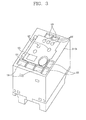
- FIG. 3 is a perspective view illustrating the configuration of communication modules G1, G2, G3, ..., Gn only provided in a motor starter according to an embodiment of the present invention.
- reference numerals in FIG. 3 use the same reference numerals in FIG. 2 if they correspond to each other.
- a motor starter may include communication modules G1, G2, G3, ..., Gn capable of performing communication with the monitoring control console 300 and the other motor starters, and the communication modules G1, G2, G3, ..., Gn may include a connection terminal 121 connected to a signal line for controlling the MC; a switch 122 for setting a communication ID; a switch 123 for setting a communication speed; a second power source terminal 124 for receiving the electric power of DC 110/220 V; a communication cable connection terminal 125 for connecting a communication cable between each of the motor starters 120-1, 120-2, 120-3, ..., 120-n; a first display unit 126 for displaying the on/off of the MC, whether or not the communication status is normal, and whether or not the communication module is normally operated; a manual control switch 127 for operating the MC to be turned on or off manually; and a first power source terminal 128 for receiving the electric power of 12 V as illustrated in FIG. 3 .
- each terminal and display means may be also arranged in a different manner if it has the same function.
- FIG. 4 is a functional block diagram illustrating the configuration of an internal circuit function unit in the communication module of a motor starter according to an embodiment of the present invention.
- reference numeral 200 is designated to the communication module of the motor starter contrary to the existing reference numerals " G1, G2, G3, ..., Gn".
- the communication module 200 of a motor starter may include an MC status input unit 210, an MMS status input unit 220, a display unit 230, a communication unit 240, and a controller 250.
- the MC status input unit 210 is connected to an MC status contact 211 of the MC to receive status information (hereinafter, referred to as "MC status information").
- the MMS status input unit 220 is connected to an MMS status contact 211 of the MMS to receive status information (hereinafter, referred to as "MMS status information").
- the display unit 230 has a function of displaying the on/off of the MC, whether or not the communication status is normal, and whether or not the communication module is normally operated.
- the communication unit 240 has a function of transmitting MC status information received through the MC status input unit 210 and status information received through the MMS status input unit 220 to the monitoring control console 300.
- the communication unit 240 is connected to the monitoring control console 300 through the communication cable 201, and transmits status information to the monitoring control console 300 under control of the controller 250 which will be described later when there is a request from the monitoring control console 300.
- the controller 250 When an command signal for operating the MC to be turned on is transmitted from the monitoring control console 300 to the communication module 200 of the motor starter, the controller 250 reads the MC status information and MMS status information, and transmits an ON command signal to the MC coil (in other words, magnetic coil) 260 when the current MC status information is off and the MMS status information is on, namely, when the MC is in an opened switching status and the MMS is in a closed switching status, thereby operating the MC to be in an ON status, namely, in a closed switching status while at the same time transmitting a control complete report signal to the monitoring control console 300.
- the MC coil in other words, magnetic coil
- the controller 250 transmits an NAK message indicating a negative response to the monitoring control console 300 without transmitting an ON command signal to the MC coil 260 of the MC when the MC status information is on and the MMS status information is off in advance.
- the controller 250 reads the MC status information and MMS status information, and normally performs the transmission of a control command signal and transmits a control complete report signal to the monitoring control console 300 when the current MC status information is on and the MMS status information is off. In other words, the controller 250 transmits an OFF command signal to the MC coil 260 to demagnetize the MC coil 260, thereby operating the MC to be in an off state, namely, in a opened switching status and transmitting a control complete report signal to the monitoring control console 300
- the controller 250 reads the MC status information and MMS status information, and transmits an NAK message to the monitoring control console 300 without performing the transmission of a control command signal when the MC status information is off and the MMS status information off.
- the controller 250 when an command signal for operating the MC to be turned off is received from the monitoring control console 300, the controller 250 periodically receives the MMS status information from the MMS status contact 221 of the MMS, and if the current MC status information is on when the MMS status information is changed from on (closed switching status) to off (opened switching status), the controller 250 transmits an off command signal to the MC coil 260 of the MC to demagnetize the MC coil 260, thereby operating the MC to be in an off state, namely, in a opened switching status.
- the monitoring control console 300 may control the MC while monitoring the MC status information and MMS status information in real time, thereby enhancing the stability of a motor control system.
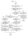
- FIG. 5 is a flow chart illustrating the operating of the motor starter according to an embodiment of the present invention.
- the controller 250 first initializes the module (S300) and sets a communication speed and communication ID (S310). Then, the controller 250 determines whether or not an MC control command signal is received from the monitoring control console 300 (S320). If the MC control command signal is not received (S320-No), then the status values of the MC and MMS are read (S330), and the read status values are transmitted to the monitor console (S340). The operation process may be carried out by the MC status input unit 210 and MMS status input unit 220.
- an ON control complete report signal (i.e., ON control complete message) is transmitted from the controller 250 to the monitoring control console 300 (S369).
- an upper monitoring control console may monitor the status of the MC in real time, thereby allowing the stable control of the MC and solving problems such as the cost increase or space limitation.
Landscapes
- Engineering & Computer Science (AREA)
- Physics & Mathematics (AREA)
- General Physics & Mathematics (AREA)
- Automation & Control Theory (AREA)
- General Engineering & Computer Science (AREA)
- Power Engineering (AREA)
- Control Of Electric Motors In General (AREA)
- Motor And Converter Starters (AREA)
Applications Claiming Priority (1)
| Application Number | Priority Date | Filing Date | Title |
|---|---|---|---|
| KR1020110124329A KR101238056B1 (ko) | 2011-11-25 | 2011-11-25 | 통신 모듈을 구비한 모터스타터 |
Publications (3)
| Publication Number | Publication Date |
|---|---|
| EP2597542A2 true EP2597542A2 (de) | 2013-05-29 |
| EP2597542A3 EP2597542A3 (de) | 2013-10-23 |
| EP2597542B1 EP2597542B1 (de) | 2015-07-15 |
Family
ID=47594267
Family Applications (1)
| Application Number | Title | Priority Date | Filing Date |
|---|---|---|---|
| EP12191849.4A Revoked EP2597542B1 (de) | 2011-11-25 | 2012-11-08 | Motoranlasser mit Kommunikationsmodul und Steuerungsverfahren des Motoranlassers |
Country Status (6)
| Country | Link |
|---|---|
| US (1) | US9594360B2 (de) |
| EP (1) | EP2597542B1 (de) |
| JP (1) | JP2013116043A (de) |
| KR (1) | KR101238056B1 (de) |
| CN (1) | CN103138653B (de) |
| ES (1) | ES2548547T3 (de) |
Families Citing this family (1)
| Publication number | Priority date | Publication date | Assignee | Title |
|---|---|---|---|---|
| GB201310193D0 (en) * | 2013-06-07 | 2013-07-24 | Trw Ltd | Motor control circuit |
Family Cites Families (18)
| Publication number | Priority date | Publication date | Assignee | Title |
|---|---|---|---|---|
| US4771274A (en) * | 1986-01-08 | 1988-09-13 | Karel Havel | Variable color digital display device |
| US5206572A (en) | 1988-06-22 | 1993-04-27 | Siemens Energy & Automation, Inc. | Motor controller |
| US5245616A (en) * | 1989-02-24 | 1993-09-14 | Rosemount Inc. | Technique for acknowledging packets |
| JP3099922B2 (ja) | 1992-12-17 | 2000-10-16 | 株式会社東芝 | 電動機制御装置 |
| FR2732523B1 (fr) | 1995-04-03 | 1997-04-25 | Schneider Electric Sa | Module d'interface entre un bus de terrain et un appareillage electrique de commande et de protection d'un moteur electrique |
| US5691871A (en) | 1995-11-14 | 1997-11-25 | Eaton Corporation | Test circuit for electrical switching device |
| US5657193A (en) | 1996-01-26 | 1997-08-12 | General Electric Company | Electronic control module for motor controller units |
| FR2763180B1 (fr) | 1997-05-09 | 1999-06-04 | Schneider Electric Sa | Procede et appareil de commande d'un depart-moteur communiquant avec un bus |
| KR20000015748A (ko) * | 1998-08-31 | 2000-03-15 | 이기원 | 무접점 소자를 이용한 디지탈 모터 콘트롤 센터 유니트 |
| DE10010290A1 (de) | 2000-03-02 | 2001-09-06 | Abb Patent Gmbh | Elektronisches Überlastrelais |
| DE10147531B4 (de) | 2001-09-26 | 2006-01-12 | Moeller Gmbh | Steuereinrichtung für einen Motorstarter |
| US6894452B2 (en) | 2002-09-23 | 2005-05-17 | Siemens Energy & Automation, Inc. | System and method for configurable motor controller settings |
| FR2858478B1 (fr) * | 2003-07-29 | 2005-09-02 | Schneider Electric Ind Sas | Ensemble de depart-moteur a cablage de controle |
| KR100632711B1 (ko) * | 2006-05-15 | 2006-10-11 | (주) 하나계전 | 모터 제어 시스템 |
| US7589942B2 (en) * | 2007-06-15 | 2009-09-15 | General Electric Company | MEMS based motor starter with motor failure detection |
| JP4924371B2 (ja) | 2007-11-13 | 2012-04-25 | 富士電機機器制御株式会社 | 回路遮断器の端子装置 |
| US8144438B2 (en) | 2008-10-03 | 2012-03-27 | General Electric Company | Motor control center communication system |
| KR100960265B1 (ko) * | 2009-10-08 | 2010-06-04 | 엔지이티(주) | 플랜트용 전동기의 제어 시스템 |
-
2011
- 2011-11-25 KR KR1020110124329A patent/KR101238056B1/ko active Active
-
2012
- 2012-11-08 EP EP12191849.4A patent/EP2597542B1/de not_active Revoked
- 2012-11-08 ES ES12191849.4T patent/ES2548547T3/es active Active
- 2012-11-16 US US13/679,908 patent/US9594360B2/en active Active
- 2012-11-20 JP JP2012254290A patent/JP2013116043A/ja active Pending
- 2012-11-23 CN CN201210484288.5A patent/CN103138653B/zh active Active
Non-Patent Citations (1)
| Title |
|---|
| None |
Also Published As
| Publication number | Publication date |
|---|---|
| US20130138228A1 (en) | 2013-05-30 |
| ES2548547T3 (es) | 2015-10-19 |
| EP2597542B1 (de) | 2015-07-15 |
| JP2013116043A (ja) | 2013-06-10 |
| EP2597542A3 (de) | 2013-10-23 |
| US9594360B2 (en) | 2017-03-14 |
| KR101238056B1 (ko) | 2013-02-27 |
| CN103138653A (zh) | 2013-06-05 |
| CN103138653B (zh) | 2016-09-21 |
Similar Documents
| Publication | Publication Date | Title |
|---|---|---|
| KR102063861B1 (ko) | 스마트 스위치를 이용하여 모터제어 기능을 수행하는 제어 네트워크 시스템 | |
| CN108933431B (zh) | 用于核电站盘车电机的启动保护电路及启动保护系统 | |
| EP2860868B1 (de) | Motorstartersystem und verfahren zum betrieb davon | |
| JP5497878B2 (ja) | モータースターターモジュール | |
| EP2597542B1 (de) | Motoranlasser mit Kommunikationsmodul und Steuerungsverfahren des Motoranlassers | |
| KR100961535B1 (ko) | 인버터 테스트 장치 | |
| CN214122414U (zh) | 一种电机堵转测试系统 | |
| CN208737262U (zh) | 物流传动多点控制装置 | |
| CN201796284U (zh) | 一种作用于控制与保护开关电器的电机集成模块 | |
| KR20070119222A (ko) | 디지탈 축소형 모자익 배전반용 차단기 테스트장치 | |
| US12401305B2 (en) | Motor management device and motor start-up and protection system comprising such a motor management device | |
| KR100823531B1 (ko) | 다종 구동소자 제어장치 | |
| KR200426099Y1 (ko) | 디지탈 축소형 모자익 배전반용 차단기 테스트장치 | |
| CN107959441B (zh) | 一种多模式电机启停电路 | |
| WO2023105584A1 (ja) | 電力変換システム、パワーモジュール及びコントロールモジュール | |
| CN108432075A (zh) | 包括保护和监测功能的电动机起动机 | |
| CN109143903A (zh) | 物流传动多点控制装置 | |
| JP2021095890A (ja) | 流体供給装置用切替システム及び流体供給システム | |
| JP2001346268A (ja) | ワイヤード付きリモコン送信機 | |
| JP2001155270A (ja) | 電源異常通報回路 | |
| JPH09265317A (ja) | 電源出力集中監視システム及び電源出力遠隔監視システム | |
| JP2010119272A (ja) | 電源系統制御装置 | |
| KR20090085919A (ko) | 무접점 릴레이를 이용한 램프 제어 장치 | |
| CN101710730A (zh) | 两电源盘的非连体自动切换方法及嵌入式控制模块 |
Legal Events
| Date | Code | Title | Description |
|---|---|---|---|
| PUAI | Public reference made under article 153(3) epc to a published international application that has entered the european phase |
Free format text: ORIGINAL CODE: 0009012 |
|
| AK | Designated contracting states |
Kind code of ref document: A2 Designated state(s): AL AT BE BG CH CY CZ DE DK EE ES FI FR GB GR HR HU IE IS IT LI LT LU LV MC MK MT NL NO PL PT RO RS SE SI SK SM TR |
|
| AX | Request for extension of the european patent |
Extension state: BA ME |
|
| PUAL | Search report despatched |
Free format text: ORIGINAL CODE: 0009013 |
|
| AK | Designated contracting states |
Kind code of ref document: A3 Designated state(s): AL AT BE BG CH CY CZ DE DK EE ES FI FR GB GR HR HU IE IS IT LI LT LU LV MC MK MT NL NO PL PT RO RS SE SI SK SM TR |
|
| AX | Request for extension of the european patent |
Extension state: BA ME |
|
| RIC1 | Information provided on ipc code assigned before grant |
Ipc: G05B 15/02 20060101ALI20130916BHEP Ipc: G05B 19/042 20060101AFI20130916BHEP |
|
| 17P | Request for examination filed |
Effective date: 20140331 |
|
| RBV | Designated contracting states (corrected) |
Designated state(s): AL AT BE BG CH CY CZ DE DK EE ES FI FR GB GR HR HU IE IS IT LI LT LU LV MC MK MT NL NO PL PT RO RS SE SI SK SM TR |
|
| REG | Reference to a national code |
Ref country code: DE Ref legal event code: R079 Ref document number: 602012008763 Country of ref document: DE Free format text: PREVIOUS MAIN CLASS: G05B0019050000 Ipc: G05B0019042000 |
|
| RIC1 | Information provided on ipc code assigned before grant |
Ipc: G05B 15/02 20060101ALI20141128BHEP Ipc: G05B 19/042 20060101AFI20141128BHEP |
|
| GRAP | Despatch of communication of intention to grant a patent |
Free format text: ORIGINAL CODE: EPIDOSNIGR1 |
|
| INTG | Intention to grant announced |
Effective date: 20150227 |
|
| GRAS | Grant fee paid |
Free format text: ORIGINAL CODE: EPIDOSNIGR3 |
|
| GRAA | (expected) grant |
Free format text: ORIGINAL CODE: 0009210 |
|
| AK | Designated contracting states |
Kind code of ref document: B1 Designated state(s): AL AT BE BG CH CY CZ DE DK EE ES FI FR GB GR HR HU IE IS IT LI LT LU LV MC MK MT NL NO PL PT RO RS SE SI SK SM TR |
|
| REG | Reference to a national code |
Ref country code: CH Ref legal event code: EP Ref country code: GB Ref legal event code: FG4D |
|
| REG | Reference to a national code |
Ref country code: IE Ref legal event code: FG4D |
|
| REG | Reference to a national code |
Ref country code: AT Ref legal event code: REF Ref document number: 737094 Country of ref document: AT Kind code of ref document: T Effective date: 20150815 |
|
| REG | Reference to a national code |
Ref country code: DE Ref legal event code: R096 Ref document number: 602012008763 Country of ref document: DE |
|
| REG | Reference to a national code |
Ref country code: ES Ref legal event code: FG2A Ref document number: 2548547 Country of ref document: ES Kind code of ref document: T3 Effective date: 20151019 |
|
| REG | Reference to a national code |
Ref country code: FR Ref legal event code: PLFP Year of fee payment: 4 |
|
| REG | Reference to a national code |
Ref country code: AT Ref legal event code: MK05 Ref document number: 737094 Country of ref document: AT Kind code of ref document: T Effective date: 20150715 |
|
| REG | Reference to a national code |
Ref country code: NL Ref legal event code: MP Effective date: 20150715 |
|
| REG | Reference to a national code |
Ref country code: LT Ref legal event code: MG4D |
|
| PG25 | Lapsed in a contracting state [announced via postgrant information from national office to epo] |
Ref country code: FI Free format text: LAPSE BECAUSE OF FAILURE TO SUBMIT A TRANSLATION OF THE DESCRIPTION OR TO PAY THE FEE WITHIN THE PRESCRIBED TIME-LIMIT Effective date: 20150715 Ref country code: LV Free format text: LAPSE BECAUSE OF FAILURE TO SUBMIT A TRANSLATION OF THE DESCRIPTION OR TO PAY THE FEE WITHIN THE PRESCRIBED TIME-LIMIT Effective date: 20150715 Ref country code: GR Free format text: LAPSE BECAUSE OF FAILURE TO SUBMIT A TRANSLATION OF THE DESCRIPTION OR TO PAY THE FEE WITHIN THE PRESCRIBED TIME-LIMIT Effective date: 20151016 Ref country code: LT Free format text: LAPSE BECAUSE OF FAILURE TO SUBMIT A TRANSLATION OF THE DESCRIPTION OR TO PAY THE FEE WITHIN THE PRESCRIBED TIME-LIMIT Effective date: 20150715 Ref country code: NO Free format text: LAPSE BECAUSE OF FAILURE TO SUBMIT A TRANSLATION OF THE DESCRIPTION OR TO PAY THE FEE WITHIN THE PRESCRIBED TIME-LIMIT Effective date: 20151015 |
|
| PG25 | Lapsed in a contracting state [announced via postgrant information from national office to epo] |
Ref country code: PT Free format text: LAPSE BECAUSE OF FAILURE TO SUBMIT A TRANSLATION OF THE DESCRIPTION OR TO PAY THE FEE WITHIN THE PRESCRIBED TIME-LIMIT Effective date: 20151116 Ref country code: SE Free format text: LAPSE BECAUSE OF FAILURE TO SUBMIT A TRANSLATION OF THE DESCRIPTION OR TO PAY THE FEE WITHIN THE PRESCRIBED TIME-LIMIT Effective date: 20150715 Ref country code: RS Free format text: LAPSE BECAUSE OF FAILURE TO SUBMIT A TRANSLATION OF THE DESCRIPTION OR TO PAY THE FEE WITHIN THE PRESCRIBED TIME-LIMIT Effective date: 20150715 Ref country code: AT Free format text: LAPSE BECAUSE OF FAILURE TO SUBMIT A TRANSLATION OF THE DESCRIPTION OR TO PAY THE FEE WITHIN THE PRESCRIBED TIME-LIMIT Effective date: 20150715 Ref country code: IS Free format text: LAPSE BECAUSE OF FAILURE TO SUBMIT A TRANSLATION OF THE DESCRIPTION OR TO PAY THE FEE WITHIN THE PRESCRIBED TIME-LIMIT Effective date: 20151115 Ref country code: PL Free format text: LAPSE BECAUSE OF FAILURE TO SUBMIT A TRANSLATION OF THE DESCRIPTION OR TO PAY THE FEE WITHIN THE PRESCRIBED TIME-LIMIT Effective date: 20150715 Ref country code: HR Free format text: LAPSE BECAUSE OF FAILURE TO SUBMIT A TRANSLATION OF THE DESCRIPTION OR TO PAY THE FEE WITHIN THE PRESCRIBED TIME-LIMIT Effective date: 20150715 |
|
| REG | Reference to a national code |
Ref country code: DE Ref legal event code: R026 Ref document number: 602012008763 Country of ref document: DE |
|
| PLBI | Opposition filed |
Free format text: ORIGINAL CODE: 0009260 |
|
| PG25 | Lapsed in a contracting state [announced via postgrant information from national office to epo] |
Ref country code: DK Free format text: LAPSE BECAUSE OF FAILURE TO SUBMIT A TRANSLATION OF THE DESCRIPTION OR TO PAY THE FEE WITHIN THE PRESCRIBED TIME-LIMIT Effective date: 20150715 Ref country code: EE Free format text: LAPSE BECAUSE OF FAILURE TO SUBMIT A TRANSLATION OF THE DESCRIPTION OR TO PAY THE FEE WITHIN THE PRESCRIBED TIME-LIMIT Effective date: 20150715 Ref country code: CZ Free format text: LAPSE BECAUSE OF FAILURE TO SUBMIT A TRANSLATION OF THE DESCRIPTION OR TO PAY THE FEE WITHIN THE PRESCRIBED TIME-LIMIT Effective date: 20150715 Ref country code: SK Free format text: LAPSE BECAUSE OF FAILURE TO SUBMIT A TRANSLATION OF THE DESCRIPTION OR TO PAY THE FEE WITHIN THE PRESCRIBED TIME-LIMIT Effective date: 20150715 |
|
| PLAX | Notice of opposition and request to file observation + time limit sent |
Free format text: ORIGINAL CODE: EPIDOSNOBS2 |
|
| 26 | Opposition filed |
Opponent name: SIEMENS AKTIENGESELLSCHAFT Effective date: 20160414 |
|
| PG25 | Lapsed in a contracting state [announced via postgrant information from national office to epo] |
Ref country code: RO Free format text: LAPSE BECAUSE OF FAILURE TO SUBMIT A TRANSLATION OF THE DESCRIPTION OR TO PAY THE FEE WITHIN THE PRESCRIBED TIME-LIMIT Effective date: 20150715 |
|
| PG25 | Lapsed in a contracting state [announced via postgrant information from national office to epo] |
Ref country code: MC Free format text: LAPSE BECAUSE OF FAILURE TO SUBMIT A TRANSLATION OF THE DESCRIPTION OR TO PAY THE FEE WITHIN THE PRESCRIBED TIME-LIMIT Effective date: 20150715 Ref country code: LU Free format text: LAPSE BECAUSE OF FAILURE TO SUBMIT A TRANSLATION OF THE DESCRIPTION OR TO PAY THE FEE WITHIN THE PRESCRIBED TIME-LIMIT Effective date: 20151108 |
|
| REG | Reference to a national code |
Ref country code: CH Ref legal event code: PL |
|
| PG25 | Lapsed in a contracting state [announced via postgrant information from national office to epo] |
Ref country code: LI Free format text: LAPSE BECAUSE OF NON-PAYMENT OF DUE FEES Effective date: 20151130 Ref country code: CH Free format text: LAPSE BECAUSE OF NON-PAYMENT OF DUE FEES Effective date: 20151130 |
|
| REG | Reference to a national code |
Ref country code: IE Ref legal event code: MM4A |
|
| PLAF | Information modified related to communication of a notice of opposition and request to file observations + time limit |
Free format text: ORIGINAL CODE: EPIDOSCOBS2 |
|
| PG25 | Lapsed in a contracting state [announced via postgrant information from national office to epo] |
Ref country code: SI Free format text: LAPSE BECAUSE OF FAILURE TO SUBMIT A TRANSLATION OF THE DESCRIPTION OR TO PAY THE FEE WITHIN THE PRESCRIBED TIME-LIMIT Effective date: 20150715 |
|
| REG | Reference to a national code |
Ref country code: FR Ref legal event code: PLFP Year of fee payment: 5 |
|
| PG25 | Lapsed in a contracting state [announced via postgrant information from national office to epo] |
Ref country code: IE Free format text: LAPSE BECAUSE OF NON-PAYMENT OF DUE FEES Effective date: 20151108 |
|
| PLBB | Reply of patent proprietor to notice(s) of opposition received |
Free format text: ORIGINAL CODE: EPIDOSNOBS3 |
|
| PG25 | Lapsed in a contracting state [announced via postgrant information from national office to epo] |
Ref country code: BE Free format text: LAPSE BECAUSE OF FAILURE TO SUBMIT A TRANSLATION OF THE DESCRIPTION OR TO PAY THE FEE WITHIN THE PRESCRIBED TIME-LIMIT Effective date: 20150715 |
|
| PG25 | Lapsed in a contracting state [announced via postgrant information from national office to epo] |
Ref country code: HU Free format text: LAPSE BECAUSE OF FAILURE TO SUBMIT A TRANSLATION OF THE DESCRIPTION OR TO PAY THE FEE WITHIN THE PRESCRIBED TIME-LIMIT; INVALID AB INITIO Effective date: 20121108 Ref country code: SM Free format text: LAPSE BECAUSE OF FAILURE TO SUBMIT A TRANSLATION OF THE DESCRIPTION OR TO PAY THE FEE WITHIN THE PRESCRIBED TIME-LIMIT Effective date: 20150715 Ref country code: BG Free format text: LAPSE BECAUSE OF FAILURE TO SUBMIT A TRANSLATION OF THE DESCRIPTION OR TO PAY THE FEE WITHIN THE PRESCRIBED TIME-LIMIT Effective date: 20150715 |
|
| PG25 | Lapsed in a contracting state [announced via postgrant information from national office to epo] |
Ref country code: CY Free format text: LAPSE BECAUSE OF FAILURE TO SUBMIT A TRANSLATION OF THE DESCRIPTION OR TO PAY THE FEE WITHIN THE PRESCRIBED TIME-LIMIT Effective date: 20150715 Ref country code: NL Free format text: LAPSE BECAUSE OF FAILURE TO SUBMIT A TRANSLATION OF THE DESCRIPTION OR TO PAY THE FEE WITHIN THE PRESCRIBED TIME-LIMIT Effective date: 20150715 |
|
| PG25 | Lapsed in a contracting state [announced via postgrant information from national office to epo] |
Ref country code: MT Free format text: LAPSE BECAUSE OF FAILURE TO SUBMIT A TRANSLATION OF THE DESCRIPTION OR TO PAY THE FEE WITHIN THE PRESCRIBED TIME-LIMIT Effective date: 20150715 |
|
| REG | Reference to a national code |
Ref country code: FR Ref legal event code: PLFP Year of fee payment: 6 |
|
| PGFP | Annual fee paid to national office [announced via postgrant information from national office to epo] |
Ref country code: GB Payment date: 20170906 Year of fee payment: 6 Ref country code: FR Payment date: 20170908 Year of fee payment: 6 |
|
| PLAB | Opposition data, opponent's data or that of the opponent's representative modified |
Free format text: ORIGINAL CODE: 0009299OPPO |
|
| R26 | Opposition filed (corrected) |
Opponent name: SIEMENS AKTIENGESELLSCHAFT Effective date: 20160414 |
|
| PGFP | Annual fee paid to national office [announced via postgrant information from national office to epo] |
Ref country code: DE Payment date: 20170906 Year of fee payment: 6 |
|
| PGFP | Annual fee paid to national office [announced via postgrant information from national office to epo] |
Ref country code: IT Payment date: 20171117 Year of fee payment: 6 Ref country code: ES Payment date: 20171214 Year of fee payment: 6 |
|
| PG25 | Lapsed in a contracting state [announced via postgrant information from national office to epo] |
Ref country code: MK Free format text: LAPSE BECAUSE OF FAILURE TO SUBMIT A TRANSLATION OF THE DESCRIPTION OR TO PAY THE FEE WITHIN THE PRESCRIBED TIME-LIMIT Effective date: 20150715 Ref country code: TR Free format text: LAPSE BECAUSE OF FAILURE TO SUBMIT A TRANSLATION OF THE DESCRIPTION OR TO PAY THE FEE WITHIN THE PRESCRIBED TIME-LIMIT Effective date: 20150715 |
|
| PG25 | Lapsed in a contracting state [announced via postgrant information from national office to epo] |
Ref country code: AL Free format text: LAPSE BECAUSE OF FAILURE TO SUBMIT A TRANSLATION OF THE DESCRIPTION OR TO PAY THE FEE WITHIN THE PRESCRIBED TIME-LIMIT Effective date: 20150715 |
|
| RDAF | Communication despatched that patent is revoked |
Free format text: ORIGINAL CODE: EPIDOSNREV1 |
|
| STAA | Information on the status of an ep patent application or granted ep patent |
Free format text: STATUS: THE PATENT HAS BEEN GRANTED |
|
| REG | Reference to a national code |
Ref country code: DE Ref legal event code: R064 Ref document number: 602012008763 Country of ref document: DE Ref country code: DE Ref legal event code: R103 Ref document number: 602012008763 Country of ref document: DE |
|
| RDAG | Patent revoked |
Free format text: ORIGINAL CODE: 0009271 |
|
| STAA | Information on the status of an ep patent application or granted ep patent |
Free format text: STATUS: PATENT REVOKED |
|
| 27W | Patent revoked |
Effective date: 20190304 |
|
| GBPR | Gb: patent revoked under art. 102 of the ep convention designating the uk as contracting state |
Effective date: 20190304 |
|
| PG25 | Lapsed in a contracting state [announced via postgrant information from national office to epo] |
Ref country code: ES Free format text: LAPSE BECAUSE OF NON-PAYMENT OF DUE FEES Effective date: 20181109 |
|
| PG25 | Lapsed in a contracting state [announced via postgrant information from national office to epo] |
Ref country code: ES Free format text: LAPSE BECAUSE OF NON-PAYMENT OF DUE FEES Effective date: 20181109 |