EP2596552B1 - Element de sertissage pour connexion sertie - Google Patents
Element de sertissage pour connexion sertie Download PDFInfo
- Publication number
- EP2596552B1 EP2596552B1 EP11732450.9A EP11732450A EP2596552B1 EP 2596552 B1 EP2596552 B1 EP 2596552B1 EP 11732450 A EP11732450 A EP 11732450A EP 2596552 B1 EP2596552 B1 EP 2596552B1
- Authority
- EP
- European Patent Office
- Prior art keywords
- zone
- crimp
- crimping
- base part
- crimp barrel
- Prior art date
- Legal status (The legal status is an assumption and is not a legal conclusion. Google has not performed a legal analysis and makes no representation as to the accuracy of the status listed.)
- Active
Links
Images


Classifications
-
- H—ELECTRICITY
- H01—ELECTRIC ELEMENTS
- H01R—ELECTRICALLY-CONDUCTIVE CONNECTIONS; STRUCTURAL ASSOCIATIONS OF A PLURALITY OF MUTUALLY-INSULATED ELECTRICAL CONNECTING ELEMENTS; COUPLING DEVICES; CURRENT COLLECTORS
- H01R4/00—Electrically-conductive connections between two or more conductive members in direct contact, i.e. touching one another; Means for effecting or maintaining such contact; Electrically-conductive connections having two or more spaced connecting locations for conductors and using contact members penetrating insulation
- H01R4/10—Electrically-conductive connections between two or more conductive members in direct contact, i.e. touching one another; Means for effecting or maintaining such contact; Electrically-conductive connections having two or more spaced connecting locations for conductors and using contact members penetrating insulation effected solely by twisting, wrapping, bending, crimping, or other permanent deformation
- H01R4/18—Electrically-conductive connections between two or more conductive members in direct contact, i.e. touching one another; Means for effecting or maintaining such contact; Electrically-conductive connections having two or more spaced connecting locations for conductors and using contact members penetrating insulation effected solely by twisting, wrapping, bending, crimping, or other permanent deformation by crimping
- H01R4/20—Electrically-conductive connections between two or more conductive members in direct contact, i.e. touching one another; Means for effecting or maintaining such contact; Electrically-conductive connections having two or more spaced connecting locations for conductors and using contact members penetrating insulation effected solely by twisting, wrapping, bending, crimping, or other permanent deformation by crimping using a crimping sleeve
-
- H—ELECTRICITY
- H01—ELECTRIC ELEMENTS
- H01R—ELECTRICALLY-CONDUCTIVE CONNECTIONS; STRUCTURAL ASSOCIATIONS OF A PLURALITY OF MUTUALLY-INSULATED ELECTRICAL CONNECTING ELEMENTS; COUPLING DEVICES; CURRENT COLLECTORS
- H01R4/00—Electrically-conductive connections between two or more conductive members in direct contact, i.e. touching one another; Means for effecting or maintaining such contact; Electrically-conductive connections having two or more spaced connecting locations for conductors and using contact members penetrating insulation
- H01R4/10—Electrically-conductive connections between two or more conductive members in direct contact, i.e. touching one another; Means for effecting or maintaining such contact; Electrically-conductive connections having two or more spaced connecting locations for conductors and using contact members penetrating insulation effected solely by twisting, wrapping, bending, crimping, or other permanent deformation
- H01R4/18—Electrically-conductive connections between two or more conductive members in direct contact, i.e. touching one another; Means for effecting or maintaining such contact; Electrically-conductive connections having two or more spaced connecting locations for conductors and using contact members penetrating insulation effected solely by twisting, wrapping, bending, crimping, or other permanent deformation by crimping
- H01R4/183—Electrically-conductive connections between two or more conductive members in direct contact, i.e. touching one another; Means for effecting or maintaining such contact; Electrically-conductive connections having two or more spaced connecting locations for conductors and using contact members penetrating insulation effected solely by twisting, wrapping, bending, crimping, or other permanent deformation by crimping for cylindrical elongated bodies, e.g. cables having circular cross-section
- H01R4/184—Electrically-conductive connections between two or more conductive members in direct contact, i.e. touching one another; Means for effecting or maintaining such contact; Electrically-conductive connections having two or more spaced connecting locations for conductors and using contact members penetrating insulation effected solely by twisting, wrapping, bending, crimping, or other permanent deformation by crimping for cylindrical elongated bodies, e.g. cables having circular cross-section comprising a U-shaped wire-receiving portion
-
- H—ELECTRICITY
- H01—ELECTRIC ELEMENTS
- H01R—ELECTRICALLY-CONDUCTIVE CONNECTIONS; STRUCTURAL ASSOCIATIONS OF A PLURALITY OF MUTUALLY-INSULATED ELECTRICAL CONNECTING ELEMENTS; COUPLING DEVICES; CURRENT COLLECTORS
- H01R13/00—Details of coupling devices of the kinds covered by groups H01R12/70 or H01R24/00 - H01R33/00
- H01R13/02—Contact members
- H01R13/04—Pins or blades for co-operation with sockets
- H01R13/05—Resilient pins or blades
-
- H—ELECTRICITY
- H01—ELECTRIC ELEMENTS
- H01R—ELECTRICALLY-CONDUCTIVE CONNECTIONS; STRUCTURAL ASSOCIATIONS OF A PLURALITY OF MUTUALLY-INSULATED ELECTRICAL CONNECTING ELEMENTS; COUPLING DEVICES; CURRENT COLLECTORS
- H01R43/00—Apparatus or processes specially adapted for manufacturing, assembling, maintaining, or repairing of line connectors or current collectors or for joining electric conductors
- H01R43/16—Apparatus or processes specially adapted for manufacturing, assembling, maintaining, or repairing of line connectors or current collectors or for joining electric conductors for manufacturing contact members, e.g. by punching and by bending
Definitions
- the invention relates to a crimping sleeve and a connecting element with such a crimping sleeve
- Joining methods in which two components are mechanically connected by plastic deformation, are used inter alia in electrical engineering. Such mechanical joining methods are also referred to as crimping and represent an alternative to conventional connections such as soldering or welding. Crimping is used in particular for creating a homogeneous, difficult to detach connection between conductor and connecting element, which ensures high electrical and mechanical safety.
- the connecting element is often a plug with a corresponding crimp barrel. Wherever the laying of a finished cable with plugs is not easily possible, the cable is laid alone to the destination and only there an electrical contact part (eg by crimping a plug) attached to the end of the line.
- crimping tool or crimping tool
- the crimping sleeve of the connector and the cable are frictionally connected.
- This usually works via a knee lever, because the manual force is too weak for a permanent deformation process of the crimp barrel.
- this type of connection has prevailed, since in addition to the connection security also brings a considerable simplification of handling with it.
- This process is carried out with the help of a special crimping tool.
- the tool and the pressing force of the crimping tool must be adapted exactly to the crimp barrel.
- crimping profiles which are precisely matched to the crimping sleeve and the conductor cross-section are used to achieve a precisely predetermined deformation of the crimping sleeve and the conductor.
- document DE 102008004680 A discloses a crimp barrel whose formation enables crimping of conductors in the small cross-sectional area from 0.08 mm 2 to 0.13 mm 2 . Since the conductor cross-sections can also be significantly larger (for example 0.35 mm 2 ), different crimping sleeves and crimping tools suitable for these cross-sections must be available on site. It would therefore be desirable to provide crimp sleeves that are equally suitable for cables of different cross-sections and therefore can be mounted by the same crimping tool.
- JP 2004 303 526 A shows a crimping sleeve according to the preamble of claim 1.
- the interaction of a relatively thick base part and inventively thinner Crimerieln is crucial that you can produce a reliable crimp connection between crimping sleeve and cable with this crimping sleeve both for larger, but also for smaller cross-sections of cables equally.
- the base part must have sufficient mass to form a solid ground for the connection element with a fixed connection Crimhülse cable after crimp connection.
- the base part may have, for example, a thickness of 0.8 mm, with which, for example, cables with cross sections between 0.35 mm 2 and 0.75 mm 2 can be reliably crimped with a crimp barrel according to the invention.
- the tapering of the thickness of the first region of the Crimpulatel is necessary so that on the one hand still enough material in the lateral region of the crimped connection is present and on the other hand, by means of the thus set ratio between the height and width of the crimp an optimal Leitverdichtung can be achieved.
- Rejuvenation is here the reduction of the thickness of the Crimpulatel referred to, which can be uniform or non-uniform.
- the thickness of the middle region may be between 0.4 mm and 0.5 mm.
- the term area designates a section in the Crimpulatel with a viewed perpendicular to the intended cable direction length.
- the shape of the tapers can be any suitable shape when seen in a lateral section. It can for example be monotone or be provided with a contour (non-monotone). Examples of a monotonous rejuvenation would be a taper along a circular arc or a linear rejuvenation. The person skilled in the art may also consider other forms of rejuvenation in the context of the present invention.
- any form of compounds is referred to by means of exerting a mechanical pressure on an enclosed by a sleeve object by means of material deformation of the sleeve and the object (squeezing) produces a mechanically strong connection.
- the enclosed object when crimping cables is the stripped cable in order to be able to produce a good electrical contact with the crimp barrel by means of a crimp connection.
- the term "sleeve” does not necessarily mean a closed mold before making the crimp, also referred to herein as crimp.
- sleeves may be open or closed sleeves prior to making the crimped connection, into which the stripped cable is laid or plugged.
- Open sleeves are usually provided in a pre-bent (crimp) form so that the crimp can be easily made by means of a suitably shaped tool.
- the crimping mold preferably has a V-shaped shape rounded at the bottom, in which the base part and the first regions of the Crimpulatel form the base of the rounded V-shape.
- the completed crimped connection has a bottom and side portion which has an approximately rectangular cross-section.
- the side on which the crimping blades touch by means of a crimping tool curl up and press on the cable underneath is called the top of the crimped connection. Accordingly, the opposite part (bottom portion) of the crimping sleeve is referred to as the bottom.
- the parts between the bottom and the top are the above-mentioned side portions.
- the first side is the side of the crimping sleeve which completely faces the cable after the crimped connection is made.
- the second side is the opposite side of the first side of the crimping sleeve.
- the second side of the crimp blades refers to the side of the crimp blades that faces away from the cable at least in the bottom region and in the side regions after a crimped connection has been made.
- the crimp sleeves according to the present invention must be made of an easily deformable and electrically conductive material, such as copper alloy (for example brass, bronze, copper, nickel silver), steel or aluminum alloys, at least in the region of the base part and the Crimperiel.
- Crimp wings can for example have a rectangular cross-section in the direction from the base part to the second area. So that the electric current can be transmitted from the cable via the crimping sleeve, for example, to an electrical device, the crimping sleeve is preferably part of a connecting element that is provided for connection to the electrical device, and / or connected thereto via an electrically conductive path.
- Crimping tools are commercially available tools for producing a Crimp connection between crimping sleeve and an electrical cable, for example, hand crimping tools.
- clamp here includes all types of electrical cables with suitable cross-sections, for example, single or multi-wire cables or cables of a variety of fine strands.
- the base part has a constant thickness in the non-curved state.
- This thickness can be, for example, 0.8 mm.
- the base must be of sufficient mass to form a solid ground for the crimped-sleeve connector after the crimped connection has been made.
- a constant thickness of the base part is advantageous, so that the base part has sufficient stability as a contact area under the cable for the pressure exerted during the production of the crimped connection.
- a constant thickness brings a stable crimp floor.
- the first region has at least one first sub-region adjacent to the base part and at least one second sub-region subsequent to the middle region, wherein the taper in the first and second sub-regions has different strengths in the un-curved state.
- the taper in the first sub-area is stronger than in the second sub-area, since the Crimperiel are curved more in the first sub-area for producing the crimping mold than in the second sub-area.
- the term "stronger" here refers to a linear taper with a greater slope. In this way, a nearly circular curved first side can be easily generated.
- the first subarea adjoins the second subarea for this purpose.
- the taper in the first and second subregions is implemented linearly with different pitch. Both embodiments can also be combined. If the tapers in the second sub-area were stronger than in the first sub-area, a circular first side in the V-shaped crimp would be difficult to manufacture and the support for the cable to be crimped would be less favorable, leaving more room for slippage of the cable.
- the taper between base and mid-section should be as steep as possible to maximize the crimp treads in the crimped state. This supports an ideal crimping behavior.
- the lateral extent of the base part and the Crimpinatel is adapted so that a bottom part in the crimped state consists of the base part and the first sub-areas.
- a bottom part in the crimped state consists of the base part and the first sub-areas.
- the rejuvenation of the second regions can for example be monotonous or be provided with a contour (non-monotone).
- An example of a monotonous rejuvenation would be a taper along a circular arc.
- the person skilled in the art may also consider other forms of rejuvenation in the context of the present invention.
- the second regions of the Crimpulatel taper linearly in the non-curved state.
- the second region tapers with a slope of approximately 20 ° relative to the second side in the middle region.
- the end faces of the second area are in the non-curved state of the Crimpulatel perpendicular to the second side of the first and second areas and the Base.
- This second-side linear taper of the second portion results in crimping of the crimp blades in the form of a worm during crimping (manufacture of the crimped connection) which presses on the cable as a common large surface. This prevents the second areas of the Crimpulatel remain during the crimping as a sharp front pages and so push through the cable and possibly shear one or more cable wires. Rolling the second sections into a screw provides a reliable, firm crimp connection with the cable.
- the thickness of the linear regions of the second regions is adjusted so that the second sides of the second regions are substantially parallel to one another in a crimp barrel in an open crimp mold of V-shape. This facilitates insertion into the crimping die of the crimping tool, resulting in a good crimping process.
- substantially includes all crimp shapes that differ by a few degrees from exact parallelism of the crimped blades in the second regions.
- the middle region tapers in the unconstrained state along the first side towards the second region.
- the crimp pad thickness is defined so that the ratio of material thickness to cross-sectional shape is similar to a standard crimp barrel.
- the portion of the central region facing the first region may, for example, have a thickness of 0.5 mm, which tapers towards the second region, for example to 0.4 mm.
- This taper is preferably linear.
- the taper of the central region of the first side equally extends over the second region.
- the second side of the Crimpinatel outside the second region and the underside of the base part in the un-curved state form a planar surface. This is advantageous in terms of production technology (for example in a stamping process) in the production of the crimp blades. Since the deformations can be made more easily from above, it is advantageous if the underside remains flat.
- the invention further relates to a connecting element with crimp sleeve according to the present invention.
- a connection element preferably further comprises at least one insulation crimp for holding a cable (with or without insulation) and a functional part in electrical contact with the crimping sleeve.
- the insulation crimp protects the crimped connection between cable and crimp sleeve against mechanical influences such as bending, bending and tensile stress, as well as vibrations, all of which, with good crimping, only act on the insulation crimp.
- the insulation crimp can be made of any material that is sufficiently mechanically deformable for a sufficiently good crimp connection.
- the insulation crimp is made of the same material as the crimping sleeve.
- the entire connecting element is made of the same electrically conductive material, for example brass, bronze, copper, nickel silver or steel.
- Preferred as the functional part is a plug. This allows a good connection with the functional part.
- Fig.1 Crimp sleeve according to the prior art in pre-bent form (crimping).
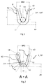
- Fig.2 Crimping sleeve according to the present invention in pre-bent form (crimping form).
- Fig.3 Crimping sleeve according to the present invention in non-curved shape.
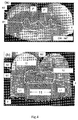
- Fig.4 Crimp connection between crimping sleeve and cable (a) according to the prior art, and (b) according to the present invention
- Fig.5 Embodiment of a connecting element according to the present invention
- illustration 1 shows a crimp barrel (CF-SdT) in pre-bent form in side view (section perpendicular to the later cable direction in the crimped connection) according to the prior art.
- the pre-bent shape (crimping mold CF) has the shape of a "V" with a curved base and upwardly facing crimp wings having a maximum distance BR1 from each other, the width of the crimping mold CF.
- the radius of curvature R1 of the curved base is dimensioned so that a cable 4 with a certain Cross section can be placed in the curved base. In order to achieve a suitable radius of curvature R1 for the cable 4, the base must have a thickness a1.
- the crimp barrel has a first side S1 facing the cable in the manufactured crimped connection and a second side S2 which is the side of the crimp barrel opposite to S1.
- the tips of the Crimperiel P have a thickness a2 smaller than the thickness a1, so that the Crimperiel can roll during crimping.
- Figure 2 shows a crimp barrel 1 in pre-bent shape (crimp CF) as a section along the direction AA, see also Figure 5 .
- the pre-bent crimping mold CF also has the shape of a "V" with a curved base portion 11 and upwardly facing crimp wings 12 having a maximum distance BR2 from each other, the width of the crimping mold CF.
- the radius of curvature R2 of the curved base is dimensioned so that a cable (not shown here for reasons of clarity) with a certain cross-section can be placed in the curved base.
- the base In order for a suitable radius of curvature R2 for the cable 4 to be achieved, the base must have a thickness d1.
- the first region of the Crimperiel 12 connects, which as shown here into two subregions L1 and L2 (shown hatched in the left Crimperiel) is divided.
- the first region could also be implemented without subdividing into subregions.
- the crimp wings 12 taper significantly in the subregions L1 and L2, so that a suitable radius of curvature can be generated for the respective cables with different cross sections.
- the crimp barrel 1 has a first side S1 which faces the cable in the manufactured crimped connection and a second side S2 which is the side of the crimp barrel 1 opposite to S1.
- the middle region of the Crimperiel 12 has a thickness d2 smaller than the thickness d1, which further tapers in the second region of the Crimperiel V2, so that the Crimperiel 12 can crimp suitable for cables with small cross-sections during crimping.
- Figure 3 shows a crimp barrel in uncurved form UK as a section along the direction AA, see also Figure 5 .
- the base part 11 with a thickness d1 (eg 0.8 mm) and a lateral extent D (perpendicular to the later cable direction in the crimped connection) forms the central area of the crimp barrel 1.
- the crimp prong 12 closes on the base part on both sides each a first area B1, a middle area MB and a second area B2.
- the Crimperiel 12 are with the first areas B1 with the base part 11 on the full length of the Crimperiel 12 (see Figure 5 ) connected.
- the thickness of the crimping tab 12 clearly tapers in the first region B1, the second one Subregions L1, L2 comprises (shown hatched).
- the taper V11 in the first subregion L1 is stronger (larger reduction in thickness) than the taper V12 in the second subregion L2.
- the middle area MB of the crimp wings 12 then adjoins the first area B1, for example with a thickness of 0.5 mm at the boundary to the first area B2.
- the crimped blades 12 continue to taper, but not as strongly as in the first region B1. If we lengthen the first side S1 along the surface of the middle area MB, the result is a taper angle ⁇ with the imaginary extended side S2, which is flat in the base part 11, the first area and the middle area BM (see dashed lines).
- the second area B2 has a first side S1, which extends in accordance with the surface of the central area MB uniformly, ie with the same taper angle, along the second area B2.
- the other opposite side S2 of the second region B2 tapers significantly towards the top of the Crimpulatel 12.
- the second region B2 has, at the boundary to the middle region MB, a thickness d2 (eg 0.4 mm) that is significantly greater than the thickness d3 (eg 0.15 mm) of the second region B2 at its tip.
- the taper V2 in this example is designed so that the second side S2 in the region of the second region B2 encloses an angle to the end face of the second region B2 of approximately 70 °. This corresponds to an angle of approximately 20 ° between the second sides S2 in the middle region MB and in the second region B2.
- Figure 3 further shows a section from the central area MB parallel to the base part 11.
- Figure 4 shows crimp sleeves with cables after making a crimp connection with a corresponding crimping tool for crimping sleeves (a) according to the prior art, and (b) according to the present invention.
- Figures 4 (a) and 4 (b) are not shown to scale to each other, so that ratios of one image can not be transferred directly into the other image.
- Figure 4a it can be seen that Crimphülsen according to the prior art in cables 4 with small cross-sections curl up so that the tips P of the Crimphülsen clearly pierce the cable 4 and thus optionally also can cut through the cable. On the one hand, this leads to a non-secure fit of the crimp barrel on the cable, on the other hand, the conductivities of the cable are adversely affected. Insufficient wire cross-sections in the crimped state may result in reduced conductivity in this area. In addition, the exclusion of air could not be guaranteed in such a connection, so that corrosion damage to the crimped connection could occur over time.
- Figure 4b shows an ideal form of a crimped connection with a crimping sleeve according to the present invention, wherein the crimped cable has a smaller cross-section deviating from the ideal cross-section.
- the bottom part 2 comprises the base part 11 (with a thickness of 0.8 mm) and the first subregions L1 of the two crimp wings 12.
- the lateral parts of the crimp connection rest on the outer regions of the bottom part 2.
- the crimp wings 12 roll through their inventively designed Rejuvenation easily in their second areas B2, but without piercing with sharp edges in the cable 4 (in contrast to the prior art shown in Figure 4a ).
- the crimped cable 4 with original cross section 0.5 mm 2 here has a rectangular cross-section with good holding and conductor properties.
- This shape of the side S1 or of the cable after production of the crimp connection is possible only with a crimping sleeve according to the present invention over a wide range of cable cross-sections.
- Figure 5 shows a connecting element 3 with a crimping sleeve 1 in plan view (view of Figure 2 from above).
- the section plane AA in which Figures 2 and 3 have been shown, is shown here by the line with marks "A".
- the crimp barrel has a base part 11 between the crimped wings 12.
- the crimp barrel is part of the connecting element 3, which further comprises two insulation crimps 31 for holding the cable in the area with intact cable insulation.
- the insulation crimps 31 are intended to keep mechanical stresses on the cable 4 away from the crimped connection with the stripped cable 41.
- the connecting element 3 further comprises a functional part 32, which is connected to the Crimp barrel in electrical contact is. This functional part 32 may for example be a plug for connection to an electrical device.
- the Crimperiel 12 are tapered relative to the base part 11 in their thicknesses, which in Figure 5 is shown as a hatched area. This taper may still extend towards the crimping crimp 31 and the functional part 32 for better crimped connection (see section 34) so as not to expose these parts to excessive stresses after the crimped connection is made.
- the crimping sleeve or the entire connecting element can be made of the same electrically conductive material, for example copper alloys (brass, bronze, copper, nickel silver, etc.), steel or aluminum alloys.
Landscapes
- Connections Effected By Soldering, Adhesion, Or Permanent Deformation (AREA)
Claims (10)
- Douille de sertissage (1) comprenant une partie de base (11) et au moins deux bras de sertissage déformables (12) pour réaliser une connexion sertie avec un câble (4), les bras de sertissage (12) comprenant respectivement une première zone (B1) reliée à la partie de base (11), une deuxième zone (B2) et une zone centrale (MB) située entre la première et la deuxième zone (B1, B2), et la partie de base (11) présentant une épaisseur (d1) plus importante que la zone centrale (MB) des bras de sertissage (12), la première zone (B1) allant, au moins d'un premier côté (S1), se rétrécissant (V1, B11, V12) de la partie de base (11) vers la zone centrale (MB), et la deuxième zone (B2), partant de la zone centrale (MB), continuant de se rétrécir (V2) au moins d'un deuxième côté (S2) opposé au premier côté (S1), caractérisée en ce que la partie de base (11) présente, à l'état non courbé (UK), une épaisseur constante (d1) et en ce que la première zone (B1) comporte au moins une première sous-zone (L1) faisant suite à la partie de base (11) et au moins une deuxième sous-zone (L2) faisant suite à la zone centrale (MB), le rétrécissement (V11, V12) étant d'ampleur différente dans les première et deuxième sous-zones (L1, L2) à l'état non courbé (UK) et la première sous-zone (L1) étant adjacente à la deuxième sous-zone (L2) et les rétrécissements (V11, V12) étant, dans les première et deuxième sous-zones (L1, L2), linéaires avec une pente différente.
- Douille de sertissage (1) selon la revendication 1, caractérisée en ce que la dimension latérale de la partie de base (11) et des bras de sertissage (12) est telle que, à l'état serti, une partie de fond (2) se compose de la partie de base (11) et des premières sous-zones (L1).
- Douille de sertissage (1) selon l'une des revendications précédentes, caractérisée en ce que les deuxièmes zones (B2) des bras de sertissage (12), à l'état non courbé (UK), se rétrécissent linéairement (V2).
- Douille de sertissage (1) selon la revendication 3, caractérisée en ce que l'ampleur des rétrécissements linéaires (V2) des deuxièmes zones (B2) est adaptée de telle sorte que les deuxièmes côtés (S2) des deuxièmes zones (B2) sont sensiblement parallèles entre eux dans le cas d'une douille de sertissage (1) présentant une forme de sertissage ouverte (CF).
- Douille de sertissage (1) selon l'une des revendications précédentes, caractérisée en ce que la zone centrale (MB), à l'état non courbé (UK), se rétrécit le long du premier côté (S1) en direction de la deuxième zone (B2).
- Douille de sertissage (1) selon la revendication 5, caractérisée en ce que le rétrécissement de la zone centrale (MB) du premier côté (S1) correspond au rétrécissement de la deuxième zone (B2).
- Douille de sertissage (1) selon l'une des revendications précédentes, caractérisée en ce que le deuxième côté (S2) des bras de sertissage (12) en dehors de la deuxième zone (B2) et la face inférieure de la partie de base (11) à l'état non courbé (UK) forment une surface plane.
- Élément de connexion (3) avec douille de sertissage (1) selon la revendication 1.
- Élément de connexion (3) selon la revendication 8, caractérisé en ce que l'élément de connexion (3) comprend en outre au moins un élément de sertissage isolant (31) pour le maintien d'une partie isolée d'un câble (4) et une pièce fonctionnelle (32) en contact électrique avec la douille de sertissage (1).
- Élément de connexion (3) selon la revendication 9, caractérisé en ce que la pièce fonctionnelle (32) est une fiche.
Priority Applications (1)
| Application Number | Priority Date | Filing Date | Title |
|---|---|---|---|
| PL11732450T PL2596552T3 (pl) | 2010-07-19 | 2011-07-14 | Tulejka zaciskowa do połączeń zagniatanych |
Applications Claiming Priority (2)
| Application Number | Priority Date | Filing Date | Title |
|---|---|---|---|
| DE102010031505A DE102010031505A1 (de) | 2010-07-19 | 2010-07-19 | Crimphülse für Quetschverbindungen |
| PCT/EP2011/062033 WO2012010488A1 (fr) | 2010-07-19 | 2011-07-14 | Manchon de sertissage pour connexions serties |
Publications (2)
| Publication Number | Publication Date |
|---|---|
| EP2596552A1 EP2596552A1 (fr) | 2013-05-29 |
| EP2596552B1 true EP2596552B1 (fr) | 2016-02-10 |
Family
ID=44583780
Family Applications (1)
| Application Number | Title | Priority Date | Filing Date |
|---|---|---|---|
| EP11732450.9A Active EP2596552B1 (fr) | 2010-07-19 | 2011-07-14 | Element de sertissage pour connexion sertie |
Country Status (7)
| Country | Link |
|---|---|
| US (1) | US9028284B2 (fr) |
| EP (1) | EP2596552B1 (fr) |
| CN (1) | CN103140986B (fr) |
| DE (1) | DE102010031505A1 (fr) |
| ES (1) | ES2565489T3 (fr) |
| PL (1) | PL2596552T3 (fr) |
| WO (1) | WO2012010488A1 (fr) |
Families Citing this family (8)
| Publication number | Priority date | Publication date | Assignee | Title |
|---|---|---|---|---|
| EP2876732A1 (fr) * | 2012-07-20 | 2015-05-27 | Furukawa Electric Co., Ltd. | Structure raccordée, raccord, et procédé de fabrication de structure raccordée |
| EP2876731B1 (fr) * | 2012-07-20 | 2018-05-02 | Furukawa Electric Co., Ltd. | Borne de sertissage |
| DE102014006244A1 (de) * | 2014-04-28 | 2015-10-29 | Rosenberger Hochfrequenztechnik Gmbh & Co. Kg | Crimp-Schweißverbindung |
| FR3033450B1 (fr) * | 2015-03-06 | 2017-02-17 | Delphi Int Operations Luxembourg Sarl | Procede de sertissage d'un contact electrique sur un cable et outil pour la mise en oeuvre de ce procede |
| DE102019200121A1 (de) * | 2018-01-12 | 2019-07-18 | Te Connectivity Germany Gmbh | Crimp zum Verbinden von Drähten |
| CN111786135A (zh) * | 2019-04-04 | 2020-10-16 | 安波福中央电气(上海)有限公司 | 开翼式接线端子 |
| US10950954B2 (en) | 2019-04-30 | 2021-03-16 | Lear Corporation | Terminal assembly and method |
| EP3989363A1 (fr) | 2020-10-26 | 2022-04-27 | Aptiv Technologies Limited | Terminal de sertissage électrique |
Family Cites Families (13)
| Publication number | Priority date | Publication date | Assignee | Title |
|---|---|---|---|---|
| US1631719A (en) | 1924-03-20 | 1927-06-07 | Ohio Brass Co | Connecting device |
| US2759256A (en) | 1952-06-13 | 1956-08-21 | Thomas & Betts Corp | Method and blank for securing a cable repair sleeve to a cable |
| US2930113A (en) * | 1957-07-02 | 1960-03-29 | Burndy Corp | Hook type run and tap connector and method of making a connection therewith |
| GB1474249A (en) * | 1974-01-09 | 1977-05-18 | Amp Inc | Electrical contact for flat conductor cable |
| US5396033A (en) * | 1992-12-09 | 1995-03-07 | Thomas & Betts Corporation | H-tap compression connector |
| JPH0680263U (ja) * | 1993-04-27 | 1994-11-08 | 矢崎総業株式会社 | 圧着端子 |
| DE60325446D1 (de) * | 2002-10-07 | 2009-02-05 | Tyco Electronics Amp Gmbh | Crimpverbinder |
| JP2004303526A (ja) * | 2003-03-31 | 2004-10-28 | Sumitomo Wiring Syst Ltd | 端子金具 |
| US7595727B2 (en) | 2003-05-16 | 2009-09-29 | Information Systems Laboratories, Inc. | Frangible electronic sealing security system |
| US7358856B2 (en) | 2004-03-18 | 2008-04-15 | Savi Technology, Inc. | Two-phase commit synchronizing seal state |
| US7121903B2 (en) * | 2004-09-27 | 2006-10-17 | Yazaki Corporation | Terminal |
| JP2008177028A (ja) | 2007-01-18 | 2008-07-31 | Yazaki Corp | 端子金具 |
| JP5707735B2 (ja) * | 2009-07-24 | 2015-04-30 | 住友電装株式会社 | 端子金具付き電線及び端子金具付き電線の製造方法 |
-
2010
- 2010-07-19 DE DE102010031505A patent/DE102010031505A1/de not_active Ceased
-
2011
- 2011-07-14 ES ES11732450.9T patent/ES2565489T3/es active Active
- 2011-07-14 EP EP11732450.9A patent/EP2596552B1/fr active Active
- 2011-07-14 CN CN201180044903.4A patent/CN103140986B/zh active Active
- 2011-07-14 US US13/811,251 patent/US9028284B2/en active Active
- 2011-07-14 WO PCT/EP2011/062033 patent/WO2012010488A1/fr not_active Ceased
- 2011-07-14 PL PL11732450T patent/PL2596552T3/pl unknown
Also Published As
| Publication number | Publication date |
|---|---|
| WO2012010488A1 (fr) | 2012-01-26 |
| CN103140986B (zh) | 2016-09-21 |
| DE102010031505A1 (de) | 2012-01-19 |
| CN103140986A (zh) | 2013-06-05 |
| US9028284B2 (en) | 2015-05-12 |
| US20130231012A1 (en) | 2013-09-05 |
| PL2596552T3 (pl) | 2016-07-29 |
| EP2596552A1 (fr) | 2013-05-29 |
| ES2565489T3 (es) | 2016-04-05 |
Similar Documents
| Publication | Publication Date | Title |
|---|---|---|
| EP2596552B1 (fr) | Element de sertissage pour connexion sertie | |
| EP2569825B1 (fr) | Element de contact electrique | |
| DE102005016236B4 (de) | Drahtendbereich-Pressbefestigungsstruktur | |
| DE69910154T2 (de) | Verbesserter Messerkontaktsteckverbinder bestehend aus zwei Teilen | |
| DE112009001147T5 (de) | Elektrisches Kabel mit Anschlussverbinder und Verfahren zur Herstellung eines elektrischen Kabels mit Anschlussverbinder | |
| EP2144331B1 (fr) | Contact à déplacement d'isolation et dispositif de connexion | |
| EP2362491B1 (fr) | Procédé de connexion d'une conduite électrique avec un élément de raccordement électrique | |
| DE102017209028B4 (de) | Herstellungsverfahren für Elektrokabel mit Klemme | |
| DE102005016235A1 (de) | Draht-Pressklemmverfahren | |
| DE112010002631T5 (de) | Verfahren zur Herstellung eines elektrischen Kabels mit einem Anschluss | |
| DE2519437A1 (de) | Verfahren und vorrichtung zum anschluss von flachleiterkabeln | |
| DE69603318T2 (de) | Vorrichtung für elektrische Kontakte mit Isolationsverschiebung | |
| WO2011151393A1 (fr) | Élément de contact pour ensemble connecteur | |
| EP3422480A1 (fr) | Système de contact destiné à la mise en contacte d'un tressage de blindage et d'un élément de contact | |
| DE102013205235A1 (de) | Crimpverbindung | |
| DE102018200456A1 (de) | Verfahren zur Herstellung einer mit einem Anschluss versehenen elektrischen Leitung | |
| DE102018112191A1 (de) | Anschluss für elektrischen Kabelverbinder | |
| DE102013224042A1 (de) | Anordnung für einen elektrischen Stecker | |
| DE2306136A1 (de) | Zuendkerzenklemmschraube und verfahren zu deren herstellung | |
| DE102017218154A1 (de) | Verfahren zur herstellung eines crimpanschlusses | |
| DE102017218236A1 (de) | Elektrischer Draht mit einem Anschluss und Verfahren zur Herstellung eines elektrischen Drahtes mit einem Anschluss | |
| DE102007038219B3 (de) | im Fließpressverfahren geformter Steckerstift | |
| DE3850064T2 (de) | Isolierungsschneidender Anschluss mit hohem Kontaktdruck für mehradrige Kabel. | |
| EP3850709B1 (fr) | Barre conductrice pour conducteur électrique et ensemble muni de la barre conductrice | |
| EP0918368B1 (fr) | Organe de contact pour des conducteurs électrique |
Legal Events
| Date | Code | Title | Description |
|---|---|---|---|
| PUAI | Public reference made under article 153(3) epc to a published international application that has entered the european phase |
Free format text: ORIGINAL CODE: 0009012 |
|
| 17P | Request for examination filed |
Effective date: 20130219 |
|
| AK | Designated contracting states |
Kind code of ref document: A1 Designated state(s): AL AT BE BG CH CY CZ DE DK EE ES FI FR GB GR HR HU IE IS IT LI LT LU LV MC MK MT NL NO PL PT RO RS SE SI SK SM TR |
|
| DAX | Request for extension of the european patent (deleted) | ||
| GRAP | Despatch of communication of intention to grant a patent |
Free format text: ORIGINAL CODE: EPIDOSNIGR1 |
|
| RIC1 | Information provided on ipc code assigned before grant |
Ipc: H01R 43/16 20060101ALI20150722BHEP Ipc: H01R 4/18 20060101AFI20150722BHEP Ipc: H01R 13/05 20060101ALI20150722BHEP Ipc: H01R 4/20 20060101ALI20150722BHEP |
|
| INTG | Intention to grant announced |
Effective date: 20150807 |
|
| RIN1 | Information on inventor provided before grant (corrected) |
Inventor name: ACKERMANN, DANIEL Inventor name: LENGERT, CLAUDE |
|
| GRAS | Grant fee paid |
Free format text: ORIGINAL CODE: EPIDOSNIGR3 |
|
| GRAA | (expected) grant |
Free format text: ORIGINAL CODE: 0009210 |
|
| AK | Designated contracting states |
Kind code of ref document: B1 Designated state(s): AL AT BE BG CH CY CZ DE DK EE ES FI FR GB GR HR HU IE IS IT LI LT LU LV MC MK MT NL NO PL PT RO RS SE SI SK SM TR |
|
| REG | Reference to a national code |
Ref country code: GB Ref legal event code: FG4D Free format text: NOT ENGLISH |
|
| REG | Reference to a national code |
Ref country code: AT Ref legal event code: REF Ref document number: 775050 Country of ref document: AT Kind code of ref document: T Effective date: 20160215 Ref country code: CH Ref legal event code: EP |
|
| REG | Reference to a national code |
Ref country code: IE Ref legal event code: FG4D Free format text: LANGUAGE OF EP DOCUMENT: GERMAN |
|
| REG | Reference to a national code |
Ref country code: DE Ref legal event code: R096 Ref document number: 502011008860 Country of ref document: DE |
|
| REG | Reference to a national code |
Ref country code: ES Ref legal event code: FG2A Ref document number: 2565489 Country of ref document: ES Kind code of ref document: T3 Effective date: 20160405 |
|
| REG | Reference to a national code |
Ref country code: RO Ref legal event code: EPE |
|
| REG | Reference to a national code |
Ref country code: LT Ref legal event code: MG4D |
|
| REG | Reference to a national code |
Ref country code: NL Ref legal event code: MP Effective date: 20160210 |
|
| REG | Reference to a national code |
Ref country code: FR Ref legal event code: PLFP Year of fee payment: 6 |
|
| PG25 | Lapsed in a contracting state [announced via postgrant information from national office to epo] |
Ref country code: GR Free format text: LAPSE BECAUSE OF FAILURE TO SUBMIT A TRANSLATION OF THE DESCRIPTION OR TO PAY THE FEE WITHIN THE PRESCRIBED TIME-LIMIT Effective date: 20160511 Ref country code: NO Free format text: LAPSE BECAUSE OF FAILURE TO SUBMIT A TRANSLATION OF THE DESCRIPTION OR TO PAY THE FEE WITHIN THE PRESCRIBED TIME-LIMIT Effective date: 20160510 Ref country code: FI Free format text: LAPSE BECAUSE OF FAILURE TO SUBMIT A TRANSLATION OF THE DESCRIPTION OR TO PAY THE FEE WITHIN THE PRESCRIBED TIME-LIMIT Effective date: 20160210 Ref country code: HR Free format text: LAPSE BECAUSE OF FAILURE TO SUBMIT A TRANSLATION OF THE DESCRIPTION OR TO PAY THE FEE WITHIN THE PRESCRIBED TIME-LIMIT Effective date: 20160210 |
|
| PG25 | Lapsed in a contracting state [announced via postgrant information from national office to epo] |
Ref country code: NL Free format text: LAPSE BECAUSE OF FAILURE TO SUBMIT A TRANSLATION OF THE DESCRIPTION OR TO PAY THE FEE WITHIN THE PRESCRIBED TIME-LIMIT Effective date: 20160210 Ref country code: SE Free format text: LAPSE BECAUSE OF FAILURE TO SUBMIT A TRANSLATION OF THE DESCRIPTION OR TO PAY THE FEE WITHIN THE PRESCRIBED TIME-LIMIT Effective date: 20160210 Ref country code: LT Free format text: LAPSE BECAUSE OF FAILURE TO SUBMIT A TRANSLATION OF THE DESCRIPTION OR TO PAY THE FEE WITHIN THE PRESCRIBED TIME-LIMIT Effective date: 20160210 Ref country code: RS Free format text: LAPSE BECAUSE OF FAILURE TO SUBMIT A TRANSLATION OF THE DESCRIPTION OR TO PAY THE FEE WITHIN THE PRESCRIBED TIME-LIMIT Effective date: 20160210 Ref country code: LV Free format text: LAPSE BECAUSE OF FAILURE TO SUBMIT A TRANSLATION OF THE DESCRIPTION OR TO PAY THE FEE WITHIN THE PRESCRIBED TIME-LIMIT Effective date: 20160210 Ref country code: PT Free format text: LAPSE BECAUSE OF FAILURE TO SUBMIT A TRANSLATION OF THE DESCRIPTION OR TO PAY THE FEE WITHIN THE PRESCRIBED TIME-LIMIT Effective date: 20160613 Ref country code: IS Free format text: LAPSE BECAUSE OF FAILURE TO SUBMIT A TRANSLATION OF THE DESCRIPTION OR TO PAY THE FEE WITHIN THE PRESCRIBED TIME-LIMIT Effective date: 20160610 |
|
| PG25 | Lapsed in a contracting state [announced via postgrant information from national office to epo] |
Ref country code: EE Free format text: LAPSE BECAUSE OF FAILURE TO SUBMIT A TRANSLATION OF THE DESCRIPTION OR TO PAY THE FEE WITHIN THE PRESCRIBED TIME-LIMIT Effective date: 20160210 Ref country code: DK Free format text: LAPSE BECAUSE OF FAILURE TO SUBMIT A TRANSLATION OF THE DESCRIPTION OR TO PAY THE FEE WITHIN THE PRESCRIBED TIME-LIMIT Effective date: 20160210 |
|
| REG | Reference to a national code |
Ref country code: DE Ref legal event code: R097 Ref document number: 502011008860 Country of ref document: DE |
|
| PG25 | Lapsed in a contracting state [announced via postgrant information from national office to epo] |
Ref country code: SM Free format text: LAPSE BECAUSE OF FAILURE TO SUBMIT A TRANSLATION OF THE DESCRIPTION OR TO PAY THE FEE WITHIN THE PRESCRIBED TIME-LIMIT Effective date: 20160210 Ref country code: SK Free format text: LAPSE BECAUSE OF FAILURE TO SUBMIT A TRANSLATION OF THE DESCRIPTION OR TO PAY THE FEE WITHIN THE PRESCRIBED TIME-LIMIT Effective date: 20160210 |
|
| PLBE | No opposition filed within time limit |
Free format text: ORIGINAL CODE: 0009261 |
|
| STAA | Information on the status of an ep patent application or granted ep patent |
Free format text: STATUS: NO OPPOSITION FILED WITHIN TIME LIMIT |
|
| PG25 | Lapsed in a contracting state [announced via postgrant information from national office to epo] |
Ref country code: BE Free format text: LAPSE BECAUSE OF NON-PAYMENT OF DUE FEES Effective date: 20160731 |
|
| 26N | No opposition filed |
Effective date: 20161111 |
|
| PG25 | Lapsed in a contracting state [announced via postgrant information from national office to epo] |
Ref country code: SI Free format text: LAPSE BECAUSE OF FAILURE TO SUBMIT A TRANSLATION OF THE DESCRIPTION OR TO PAY THE FEE WITHIN THE PRESCRIBED TIME-LIMIT Effective date: 20160210 Ref country code: BG Free format text: LAPSE BECAUSE OF FAILURE TO SUBMIT A TRANSLATION OF THE DESCRIPTION OR TO PAY THE FEE WITHIN THE PRESCRIBED TIME-LIMIT Effective date: 20160510 |
|
| REG | Reference to a national code |
Ref country code: CH Ref legal event code: PL |
|
| PG25 | Lapsed in a contracting state [announced via postgrant information from national office to epo] |
Ref country code: MC Free format text: LAPSE BECAUSE OF FAILURE TO SUBMIT A TRANSLATION OF THE DESCRIPTION OR TO PAY THE FEE WITHIN THE PRESCRIBED TIME-LIMIT Effective date: 20160210 |
|
| PG25 | Lapsed in a contracting state [announced via postgrant information from national office to epo] |
Ref country code: CH Free format text: LAPSE BECAUSE OF NON-PAYMENT OF DUE FEES Effective date: 20160731 Ref country code: LI Free format text: LAPSE BECAUSE OF NON-PAYMENT OF DUE FEES Effective date: 20160731 |
|
| REG | Reference to a national code |
Ref country code: IE Ref legal event code: MM4A |
|
| REG | Reference to a national code |
Ref country code: FR Ref legal event code: PLFP Year of fee payment: 7 |
|
| PG25 | Lapsed in a contracting state [announced via postgrant information from national office to epo] |
Ref country code: IE Free format text: LAPSE BECAUSE OF NON-PAYMENT OF DUE FEES Effective date: 20160714 |
|
| PG25 | Lapsed in a contracting state [announced via postgrant information from national office to epo] |
Ref country code: LU Free format text: LAPSE BECAUSE OF NON-PAYMENT OF DUE FEES Effective date: 20160714 |
|
| REG | Reference to a national code |
Ref country code: AT Ref legal event code: MM01 Ref document number: 775050 Country of ref document: AT Kind code of ref document: T Effective date: 20160714 |
|
| PG25 | Lapsed in a contracting state [announced via postgrant information from national office to epo] |
Ref country code: AT Free format text: LAPSE BECAUSE OF NON-PAYMENT OF DUE FEES Effective date: 20160714 |
|
| PG25 | Lapsed in a contracting state [announced via postgrant information from national office to epo] |
Ref country code: HU Free format text: LAPSE BECAUSE OF FAILURE TO SUBMIT A TRANSLATION OF THE DESCRIPTION OR TO PAY THE FEE WITHIN THE PRESCRIBED TIME-LIMIT; INVALID AB INITIO Effective date: 20110714 Ref country code: CY Free format text: LAPSE BECAUSE OF FAILURE TO SUBMIT A TRANSLATION OF THE DESCRIPTION OR TO PAY THE FEE WITHIN THE PRESCRIBED TIME-LIMIT Effective date: 20160210 |
|
| PG25 | Lapsed in a contracting state [announced via postgrant information from national office to epo] |
Ref country code: TR Free format text: LAPSE BECAUSE OF FAILURE TO SUBMIT A TRANSLATION OF THE DESCRIPTION OR TO PAY THE FEE WITHIN THE PRESCRIBED TIME-LIMIT Effective date: 20160210 Ref country code: MK Free format text: LAPSE BECAUSE OF FAILURE TO SUBMIT A TRANSLATION OF THE DESCRIPTION OR TO PAY THE FEE WITHIN THE PRESCRIBED TIME-LIMIT Effective date: 20160210 Ref country code: MT Free format text: LAPSE BECAUSE OF FAILURE TO SUBMIT A TRANSLATION OF THE DESCRIPTION OR TO PAY THE FEE WITHIN THE PRESCRIBED TIME-LIMIT Effective date: 20160210 |
|
| REG | Reference to a national code |
Ref country code: FR Ref legal event code: PLFP Year of fee payment: 8 |
|
| PG25 | Lapsed in a contracting state [announced via postgrant information from national office to epo] |
Ref country code: AL Free format text: LAPSE BECAUSE OF FAILURE TO SUBMIT A TRANSLATION OF THE DESCRIPTION OR TO PAY THE FEE WITHIN THE PRESCRIBED TIME-LIMIT Effective date: 20160210 |
|
| PGFP | Annual fee paid to national office [announced via postgrant information from national office to epo] |
Ref country code: ES Payment date: 20250826 Year of fee payment: 15 |
|
| PGFP | Annual fee paid to national office [announced via postgrant information from national office to epo] |
Ref country code: PL Payment date: 20250710 Year of fee payment: 15 Ref country code: IT Payment date: 20250724 Year of fee payment: 15 |
|
| PGFP | Annual fee paid to national office [announced via postgrant information from national office to epo] |
Ref country code: GB Payment date: 20250722 Year of fee payment: 15 |
|
| PGFP | Annual fee paid to national office [announced via postgrant information from national office to epo] |
Ref country code: FR Payment date: 20250725 Year of fee payment: 15 |
|
| PGFP | Annual fee paid to national office [announced via postgrant information from national office to epo] |
Ref country code: CZ Payment date: 20250711 Year of fee payment: 15 |
|
| PGFP | Annual fee paid to national office [announced via postgrant information from national office to epo] |
Ref country code: RO Payment date: 20250710 Year of fee payment: 15 |
|
| PGFP | Annual fee paid to national office [announced via postgrant information from national office to epo] |
Ref country code: DE Payment date: 20260120 Year of fee payment: 15 |