EP2596552B1 - Crimp element for crimp connection - Google Patents
Crimp element for crimp connection Download PDFInfo
- Publication number
- EP2596552B1 EP2596552B1 EP11732450.9A EP11732450A EP2596552B1 EP 2596552 B1 EP2596552 B1 EP 2596552B1 EP 11732450 A EP11732450 A EP 11732450A EP 2596552 B1 EP2596552 B1 EP 2596552B1
- Authority
- EP
- European Patent Office
- Prior art keywords
- zone
- crimp
- crimping
- base part
- crimp barrel
- Prior art date
- Legal status (The legal status is an assumption and is not a legal conclusion. Google has not performed a legal analysis and makes no representation as to the accuracy of the status listed.)
- Active
Links
Images


Classifications
-
- H—ELECTRICITY
- H01—ELECTRIC ELEMENTS
- H01R—ELECTRICALLY-CONDUCTIVE CONNECTIONS; STRUCTURAL ASSOCIATIONS OF A PLURALITY OF MUTUALLY-INSULATED ELECTRICAL CONNECTING ELEMENTS; COUPLING DEVICES; CURRENT COLLECTORS
- H01R4/00—Electrically-conductive connections between two or more conductive members in direct contact, i.e. touching one another; Means for effecting or maintaining such contact; Electrically-conductive connections having two or more spaced connecting locations for conductors and using contact members penetrating insulation
- H01R4/10—Electrically-conductive connections between two or more conductive members in direct contact, i.e. touching one another; Means for effecting or maintaining such contact; Electrically-conductive connections having two or more spaced connecting locations for conductors and using contact members penetrating insulation effected solely by twisting, wrapping, bending, crimping, or other permanent deformation
- H01R4/18—Electrically-conductive connections between two or more conductive members in direct contact, i.e. touching one another; Means for effecting or maintaining such contact; Electrically-conductive connections having two or more spaced connecting locations for conductors and using contact members penetrating insulation effected solely by twisting, wrapping, bending, crimping, or other permanent deformation by crimping
- H01R4/20—Electrically-conductive connections between two or more conductive members in direct contact, i.e. touching one another; Means for effecting or maintaining such contact; Electrically-conductive connections having two or more spaced connecting locations for conductors and using contact members penetrating insulation effected solely by twisting, wrapping, bending, crimping, or other permanent deformation by crimping using a crimping sleeve
-
- H—ELECTRICITY
- H01—ELECTRIC ELEMENTS
- H01R—ELECTRICALLY-CONDUCTIVE CONNECTIONS; STRUCTURAL ASSOCIATIONS OF A PLURALITY OF MUTUALLY-INSULATED ELECTRICAL CONNECTING ELEMENTS; COUPLING DEVICES; CURRENT COLLECTORS
- H01R4/00—Electrically-conductive connections between two or more conductive members in direct contact, i.e. touching one another; Means for effecting or maintaining such contact; Electrically-conductive connections having two or more spaced connecting locations for conductors and using contact members penetrating insulation
- H01R4/10—Electrically-conductive connections between two or more conductive members in direct contact, i.e. touching one another; Means for effecting or maintaining such contact; Electrically-conductive connections having two or more spaced connecting locations for conductors and using contact members penetrating insulation effected solely by twisting, wrapping, bending, crimping, or other permanent deformation
- H01R4/18—Electrically-conductive connections between two or more conductive members in direct contact, i.e. touching one another; Means for effecting or maintaining such contact; Electrically-conductive connections having two or more spaced connecting locations for conductors and using contact members penetrating insulation effected solely by twisting, wrapping, bending, crimping, or other permanent deformation by crimping
- H01R4/183—Electrically-conductive connections between two or more conductive members in direct contact, i.e. touching one another; Means for effecting or maintaining such contact; Electrically-conductive connections having two or more spaced connecting locations for conductors and using contact members penetrating insulation effected solely by twisting, wrapping, bending, crimping, or other permanent deformation by crimping for cylindrical elongated bodies, e.g. cables having circular cross-section
- H01R4/184—Electrically-conductive connections between two or more conductive members in direct contact, i.e. touching one another; Means for effecting or maintaining such contact; Electrically-conductive connections having two or more spaced connecting locations for conductors and using contact members penetrating insulation effected solely by twisting, wrapping, bending, crimping, or other permanent deformation by crimping for cylindrical elongated bodies, e.g. cables having circular cross-section comprising a U-shaped wire-receiving portion
-
- H—ELECTRICITY
- H01—ELECTRIC ELEMENTS
- H01R—ELECTRICALLY-CONDUCTIVE CONNECTIONS; STRUCTURAL ASSOCIATIONS OF A PLURALITY OF MUTUALLY-INSULATED ELECTRICAL CONNECTING ELEMENTS; COUPLING DEVICES; CURRENT COLLECTORS
- H01R13/00—Details of coupling devices of the kinds covered by groups H01R12/70 or H01R24/00 - H01R33/00
- H01R13/02—Contact members
- H01R13/04—Pins or blades for co-operation with sockets
- H01R13/05—Resilient pins or blades
-
- H—ELECTRICITY
- H01—ELECTRIC ELEMENTS
- H01R—ELECTRICALLY-CONDUCTIVE CONNECTIONS; STRUCTURAL ASSOCIATIONS OF A PLURALITY OF MUTUALLY-INSULATED ELECTRICAL CONNECTING ELEMENTS; COUPLING DEVICES; CURRENT COLLECTORS
- H01R43/00—Apparatus or processes specially adapted for manufacturing, assembling, maintaining, or repairing of line connectors or current collectors or for joining electric conductors
- H01R43/16—Apparatus or processes specially adapted for manufacturing, assembling, maintaining, or repairing of line connectors or current collectors or for joining electric conductors for manufacturing contact members, e.g. by punching and by bending
Definitions
- the invention relates to a crimping sleeve and a connecting element with such a crimping sleeve
- Joining methods in which two components are mechanically connected by plastic deformation, are used inter alia in electrical engineering. Such mechanical joining methods are also referred to as crimping and represent an alternative to conventional connections such as soldering or welding. Crimping is used in particular for creating a homogeneous, difficult to detach connection between conductor and connecting element, which ensures high electrical and mechanical safety.
- the connecting element is often a plug with a corresponding crimp barrel. Wherever the laying of a finished cable with plugs is not easily possible, the cable is laid alone to the destination and only there an electrical contact part (eg by crimping a plug) attached to the end of the line.
- crimping tool or crimping tool
- the crimping sleeve of the connector and the cable are frictionally connected.
- This usually works via a knee lever, because the manual force is too weak for a permanent deformation process of the crimp barrel.
- this type of connection has prevailed, since in addition to the connection security also brings a considerable simplification of handling with it.
- This process is carried out with the help of a special crimping tool.
- the tool and the pressing force of the crimping tool must be adapted exactly to the crimp barrel.
- crimping profiles which are precisely matched to the crimping sleeve and the conductor cross-section are used to achieve a precisely predetermined deformation of the crimping sleeve and the conductor.
- document DE 102008004680 A discloses a crimp barrel whose formation enables crimping of conductors in the small cross-sectional area from 0.08 mm 2 to 0.13 mm 2 . Since the conductor cross-sections can also be significantly larger (for example 0.35 mm 2 ), different crimping sleeves and crimping tools suitable for these cross-sections must be available on site. It would therefore be desirable to provide crimp sleeves that are equally suitable for cables of different cross-sections and therefore can be mounted by the same crimping tool.
- JP 2004 303 526 A shows a crimping sleeve according to the preamble of claim 1.
- the interaction of a relatively thick base part and inventively thinner Crimerieln is crucial that you can produce a reliable crimp connection between crimping sleeve and cable with this crimping sleeve both for larger, but also for smaller cross-sections of cables equally.
- the base part must have sufficient mass to form a solid ground for the connection element with a fixed connection Crimhülse cable after crimp connection.
- the base part may have, for example, a thickness of 0.8 mm, with which, for example, cables with cross sections between 0.35 mm 2 and 0.75 mm 2 can be reliably crimped with a crimp barrel according to the invention.
- the tapering of the thickness of the first region of the Crimpulatel is necessary so that on the one hand still enough material in the lateral region of the crimped connection is present and on the other hand, by means of the thus set ratio between the height and width of the crimp an optimal Leitverdichtung can be achieved.
- Rejuvenation is here the reduction of the thickness of the Crimpulatel referred to, which can be uniform or non-uniform.
- the thickness of the middle region may be between 0.4 mm and 0.5 mm.
- the term area designates a section in the Crimpulatel with a viewed perpendicular to the intended cable direction length.
- the shape of the tapers can be any suitable shape when seen in a lateral section. It can for example be monotone or be provided with a contour (non-monotone). Examples of a monotonous rejuvenation would be a taper along a circular arc or a linear rejuvenation. The person skilled in the art may also consider other forms of rejuvenation in the context of the present invention.
- any form of compounds is referred to by means of exerting a mechanical pressure on an enclosed by a sleeve object by means of material deformation of the sleeve and the object (squeezing) produces a mechanically strong connection.
- the enclosed object when crimping cables is the stripped cable in order to be able to produce a good electrical contact with the crimp barrel by means of a crimp connection.
- the term "sleeve” does not necessarily mean a closed mold before making the crimp, also referred to herein as crimp.
- sleeves may be open or closed sleeves prior to making the crimped connection, into which the stripped cable is laid or plugged.
- Open sleeves are usually provided in a pre-bent (crimp) form so that the crimp can be easily made by means of a suitably shaped tool.
- the crimping mold preferably has a V-shaped shape rounded at the bottom, in which the base part and the first regions of the Crimpulatel form the base of the rounded V-shape.
- the completed crimped connection has a bottom and side portion which has an approximately rectangular cross-section.
- the side on which the crimping blades touch by means of a crimping tool curl up and press on the cable underneath is called the top of the crimped connection. Accordingly, the opposite part (bottom portion) of the crimping sleeve is referred to as the bottom.
- the parts between the bottom and the top are the above-mentioned side portions.
- the first side is the side of the crimping sleeve which completely faces the cable after the crimped connection is made.
- the second side is the opposite side of the first side of the crimping sleeve.
- the second side of the crimp blades refers to the side of the crimp blades that faces away from the cable at least in the bottom region and in the side regions after a crimped connection has been made.
- the crimp sleeves according to the present invention must be made of an easily deformable and electrically conductive material, such as copper alloy (for example brass, bronze, copper, nickel silver), steel or aluminum alloys, at least in the region of the base part and the Crimperiel.
- Crimp wings can for example have a rectangular cross-section in the direction from the base part to the second area. So that the electric current can be transmitted from the cable via the crimping sleeve, for example, to an electrical device, the crimping sleeve is preferably part of a connecting element that is provided for connection to the electrical device, and / or connected thereto via an electrically conductive path.
- Crimping tools are commercially available tools for producing a Crimp connection between crimping sleeve and an electrical cable, for example, hand crimping tools.
- clamp here includes all types of electrical cables with suitable cross-sections, for example, single or multi-wire cables or cables of a variety of fine strands.
- the base part has a constant thickness in the non-curved state.
- This thickness can be, for example, 0.8 mm.
- the base must be of sufficient mass to form a solid ground for the crimped-sleeve connector after the crimped connection has been made.
- a constant thickness of the base part is advantageous, so that the base part has sufficient stability as a contact area under the cable for the pressure exerted during the production of the crimped connection.
- a constant thickness brings a stable crimp floor.
- the first region has at least one first sub-region adjacent to the base part and at least one second sub-region subsequent to the middle region, wherein the taper in the first and second sub-regions has different strengths in the un-curved state.
- the taper in the first sub-area is stronger than in the second sub-area, since the Crimperiel are curved more in the first sub-area for producing the crimping mold than in the second sub-area.
- the term "stronger" here refers to a linear taper with a greater slope. In this way, a nearly circular curved first side can be easily generated.
- the first subarea adjoins the second subarea for this purpose.
- the taper in the first and second subregions is implemented linearly with different pitch. Both embodiments can also be combined. If the tapers in the second sub-area were stronger than in the first sub-area, a circular first side in the V-shaped crimp would be difficult to manufacture and the support for the cable to be crimped would be less favorable, leaving more room for slippage of the cable.
- the taper between base and mid-section should be as steep as possible to maximize the crimp treads in the crimped state. This supports an ideal crimping behavior.
- the lateral extent of the base part and the Crimpinatel is adapted so that a bottom part in the crimped state consists of the base part and the first sub-areas.
- a bottom part in the crimped state consists of the base part and the first sub-areas.
- the rejuvenation of the second regions can for example be monotonous or be provided with a contour (non-monotone).
- An example of a monotonous rejuvenation would be a taper along a circular arc.
- the person skilled in the art may also consider other forms of rejuvenation in the context of the present invention.
- the second regions of the Crimpulatel taper linearly in the non-curved state.
- the second region tapers with a slope of approximately 20 ° relative to the second side in the middle region.
- the end faces of the second area are in the non-curved state of the Crimpulatel perpendicular to the second side of the first and second areas and the Base.
- This second-side linear taper of the second portion results in crimping of the crimp blades in the form of a worm during crimping (manufacture of the crimped connection) which presses on the cable as a common large surface. This prevents the second areas of the Crimpulatel remain during the crimping as a sharp front pages and so push through the cable and possibly shear one or more cable wires. Rolling the second sections into a screw provides a reliable, firm crimp connection with the cable.
- the thickness of the linear regions of the second regions is adjusted so that the second sides of the second regions are substantially parallel to one another in a crimp barrel in an open crimp mold of V-shape. This facilitates insertion into the crimping die of the crimping tool, resulting in a good crimping process.
- substantially includes all crimp shapes that differ by a few degrees from exact parallelism of the crimped blades in the second regions.
- the middle region tapers in the unconstrained state along the first side towards the second region.
- the crimp pad thickness is defined so that the ratio of material thickness to cross-sectional shape is similar to a standard crimp barrel.
- the portion of the central region facing the first region may, for example, have a thickness of 0.5 mm, which tapers towards the second region, for example to 0.4 mm.
- This taper is preferably linear.
- the taper of the central region of the first side equally extends over the second region.
- the second side of the Crimpinatel outside the second region and the underside of the base part in the un-curved state form a planar surface. This is advantageous in terms of production technology (for example in a stamping process) in the production of the crimp blades. Since the deformations can be made more easily from above, it is advantageous if the underside remains flat.
- the invention further relates to a connecting element with crimp sleeve according to the present invention.
- a connection element preferably further comprises at least one insulation crimp for holding a cable (with or without insulation) and a functional part in electrical contact with the crimping sleeve.
- the insulation crimp protects the crimped connection between cable and crimp sleeve against mechanical influences such as bending, bending and tensile stress, as well as vibrations, all of which, with good crimping, only act on the insulation crimp.
- the insulation crimp can be made of any material that is sufficiently mechanically deformable for a sufficiently good crimp connection.
- the insulation crimp is made of the same material as the crimping sleeve.
- the entire connecting element is made of the same electrically conductive material, for example brass, bronze, copper, nickel silver or steel.
- Preferred as the functional part is a plug. This allows a good connection with the functional part.
- Fig.1 Crimp sleeve according to the prior art in pre-bent form (crimping).
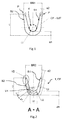
- Fig.2 Crimping sleeve according to the present invention in pre-bent form (crimping form).
- Fig.3 Crimping sleeve according to the present invention in non-curved shape.
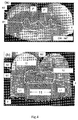
- Fig.4 Crimp connection between crimping sleeve and cable (a) according to the prior art, and (b) according to the present invention
- Fig.5 Embodiment of a connecting element according to the present invention
- illustration 1 shows a crimp barrel (CF-SdT) in pre-bent form in side view (section perpendicular to the later cable direction in the crimped connection) according to the prior art.
- the pre-bent shape (crimping mold CF) has the shape of a "V" with a curved base and upwardly facing crimp wings having a maximum distance BR1 from each other, the width of the crimping mold CF.
- the radius of curvature R1 of the curved base is dimensioned so that a cable 4 with a certain Cross section can be placed in the curved base. In order to achieve a suitable radius of curvature R1 for the cable 4, the base must have a thickness a1.
- the crimp barrel has a first side S1 facing the cable in the manufactured crimped connection and a second side S2 which is the side of the crimp barrel opposite to S1.
- the tips of the Crimperiel P have a thickness a2 smaller than the thickness a1, so that the Crimperiel can roll during crimping.
- Figure 2 shows a crimp barrel 1 in pre-bent shape (crimp CF) as a section along the direction AA, see also Figure 5 .
- the pre-bent crimping mold CF also has the shape of a "V" with a curved base portion 11 and upwardly facing crimp wings 12 having a maximum distance BR2 from each other, the width of the crimping mold CF.
- the radius of curvature R2 of the curved base is dimensioned so that a cable (not shown here for reasons of clarity) with a certain cross-section can be placed in the curved base.
- the base In order for a suitable radius of curvature R2 for the cable 4 to be achieved, the base must have a thickness d1.
- the first region of the Crimperiel 12 connects, which as shown here into two subregions L1 and L2 (shown hatched in the left Crimperiel) is divided.
- the first region could also be implemented without subdividing into subregions.
- the crimp wings 12 taper significantly in the subregions L1 and L2, so that a suitable radius of curvature can be generated for the respective cables with different cross sections.
- the crimp barrel 1 has a first side S1 which faces the cable in the manufactured crimped connection and a second side S2 which is the side of the crimp barrel 1 opposite to S1.
- the middle region of the Crimperiel 12 has a thickness d2 smaller than the thickness d1, which further tapers in the second region of the Crimperiel V2, so that the Crimperiel 12 can crimp suitable for cables with small cross-sections during crimping.
- Figure 3 shows a crimp barrel in uncurved form UK as a section along the direction AA, see also Figure 5 .
- the base part 11 with a thickness d1 (eg 0.8 mm) and a lateral extent D (perpendicular to the later cable direction in the crimped connection) forms the central area of the crimp barrel 1.
- the crimp prong 12 closes on the base part on both sides each a first area B1, a middle area MB and a second area B2.
- the Crimperiel 12 are with the first areas B1 with the base part 11 on the full length of the Crimperiel 12 (see Figure 5 ) connected.
- the thickness of the crimping tab 12 clearly tapers in the first region B1, the second one Subregions L1, L2 comprises (shown hatched).
- the taper V11 in the first subregion L1 is stronger (larger reduction in thickness) than the taper V12 in the second subregion L2.
- the middle area MB of the crimp wings 12 then adjoins the first area B1, for example with a thickness of 0.5 mm at the boundary to the first area B2.
- the crimped blades 12 continue to taper, but not as strongly as in the first region B1. If we lengthen the first side S1 along the surface of the middle area MB, the result is a taper angle ⁇ with the imaginary extended side S2, which is flat in the base part 11, the first area and the middle area BM (see dashed lines).
- the second area B2 has a first side S1, which extends in accordance with the surface of the central area MB uniformly, ie with the same taper angle, along the second area B2.
- the other opposite side S2 of the second region B2 tapers significantly towards the top of the Crimpulatel 12.
- the second region B2 has, at the boundary to the middle region MB, a thickness d2 (eg 0.4 mm) that is significantly greater than the thickness d3 (eg 0.15 mm) of the second region B2 at its tip.
- the taper V2 in this example is designed so that the second side S2 in the region of the second region B2 encloses an angle to the end face of the second region B2 of approximately 70 °. This corresponds to an angle of approximately 20 ° between the second sides S2 in the middle region MB and in the second region B2.
- Figure 3 further shows a section from the central area MB parallel to the base part 11.
- Figure 4 shows crimp sleeves with cables after making a crimp connection with a corresponding crimping tool for crimping sleeves (a) according to the prior art, and (b) according to the present invention.
- Figures 4 (a) and 4 (b) are not shown to scale to each other, so that ratios of one image can not be transferred directly into the other image.
- Figure 4a it can be seen that Crimphülsen according to the prior art in cables 4 with small cross-sections curl up so that the tips P of the Crimphülsen clearly pierce the cable 4 and thus optionally also can cut through the cable. On the one hand, this leads to a non-secure fit of the crimp barrel on the cable, on the other hand, the conductivities of the cable are adversely affected. Insufficient wire cross-sections in the crimped state may result in reduced conductivity in this area. In addition, the exclusion of air could not be guaranteed in such a connection, so that corrosion damage to the crimped connection could occur over time.
- Figure 4b shows an ideal form of a crimped connection with a crimping sleeve according to the present invention, wherein the crimped cable has a smaller cross-section deviating from the ideal cross-section.
- the bottom part 2 comprises the base part 11 (with a thickness of 0.8 mm) and the first subregions L1 of the two crimp wings 12.
- the lateral parts of the crimp connection rest on the outer regions of the bottom part 2.
- the crimp wings 12 roll through their inventively designed Rejuvenation easily in their second areas B2, but without piercing with sharp edges in the cable 4 (in contrast to the prior art shown in Figure 4a ).
- the crimped cable 4 with original cross section 0.5 mm 2 here has a rectangular cross-section with good holding and conductor properties.
- This shape of the side S1 or of the cable after production of the crimp connection is possible only with a crimping sleeve according to the present invention over a wide range of cable cross-sections.
- Figure 5 shows a connecting element 3 with a crimping sleeve 1 in plan view (view of Figure 2 from above).
- the section plane AA in which Figures 2 and 3 have been shown, is shown here by the line with marks "A".
- the crimp barrel has a base part 11 between the crimped wings 12.
- the crimp barrel is part of the connecting element 3, which further comprises two insulation crimps 31 for holding the cable in the area with intact cable insulation.
- the insulation crimps 31 are intended to keep mechanical stresses on the cable 4 away from the crimped connection with the stripped cable 41.
- the connecting element 3 further comprises a functional part 32, which is connected to the Crimp barrel in electrical contact is. This functional part 32 may for example be a plug for connection to an electrical device.
- the Crimperiel 12 are tapered relative to the base part 11 in their thicknesses, which in Figure 5 is shown as a hatched area. This taper may still extend towards the crimping crimp 31 and the functional part 32 for better crimped connection (see section 34) so as not to expose these parts to excessive stresses after the crimped connection is made.
- the crimping sleeve or the entire connecting element can be made of the same electrically conductive material, for example copper alloys (brass, bronze, copper, nickel silver, etc.), steel or aluminum alloys.
Landscapes
- Connections Effected By Soldering, Adhesion, Or Permanent Deformation (AREA)
Description
Die Erfindung betrifft eine Crimphülse und ein Verbindungselement mit einer solchen CrimphülseThe invention relates to a crimping sleeve and a connecting element with such a crimping sleeve
Fügeverfahren, bei dem zwei Komponenten durch plastische Verformung mechanisch miteinander verbunden werden, werden unter anderem in der Elektrotechnik verwendet. Solche mechanischen Fügeverfahren werden auch als Crimpen bezeichnet und stellen eine Alternative zu herkömmlichen Verbindungen wie Löten oder Schweißen dar. Crimpen wendet man insbesondere zur Erstellung einer homogenen, schwer lösbaren Verbindung zwischen Leiter und Verbindungselement, die eine hohe elektrische und mechanische Sicherheit gewährleistet, an. Das Verbindungselement ist häufig ein Stecker mit entsprechender Crimphülse. Überall da, wo die Verlegung eines fertigen Kabels mit Steckern nicht leicht möglich ist, wird das Kabel alleine bis zum Zielort verlegt und erst dort ein elektrisches Kontaktteil (z. B. durch Crimpen eines Steckers) an das Ende der Leitung angebracht.Joining methods, in which two components are mechanically connected by plastic deformation, are used inter alia in electrical engineering. Such mechanical joining methods are also referred to as crimping and represent an alternative to conventional connections such as soldering or welding. Crimping is used in particular for creating a homogeneous, difficult to detach connection between conductor and connecting element, which ensures high electrical and mechanical safety. The connecting element is often a plug with a corresponding crimp barrel. Wherever the laying of a finished cable with plugs is not easily possible, the cable is laid alone to the destination and only there an electrical contact part (eg by crimping a plug) attached to the end of the line.
Mit Hilfe einer Crimpzange (oder Crimpwerkzeug) werden Crimphülse des Steckers und Kabel kraftschlüssig verbunden. Diese wirkt meist über einen Kniehebel, weil die Handkraft zu schwach für einen dauerhaften Verformungsvorgang der Crimphülse ist. Insbesondere im Bereich der HF-Elektronik und der Telekommunikation hat sich diese Anschlussart durchgesetzt, da diese neben der Verbindungssicherheit auch eine erhebliche Vereinfachung der Handhabung mit sich bringt. Dieser Vorgang wird mit Hilfe einer speziellen Crimpzange durchgeführt. Hierbei muss das Werkzeug und die Presskraft der Crimpzange genau an die Crimphülse angepasst werden. Beim Crimpen entsteht bei korrekter Ausführung eine gasdichte Verbindung. Durch Verformung der Crimphülse und der feindrähtigen Leitung entsteht eine Struktur, die weitgehend von Sauerstoff abgeschottet ist und somit im Inneren weitgehend vor Korrosion geschützt ist.With the help of a crimping tool (or crimping tool) the crimping sleeve of the connector and the cable are frictionally connected. This usually works via a knee lever, because the manual force is too weak for a permanent deformation process of the crimp barrel. In particular, in the field of RF electronics and telecommunications, this type of connection has prevailed, since in addition to the connection security also brings a considerable simplification of handling with it. This process is carried out with the help of a special crimping tool. Here, the tool and the pressing force of the crimping tool must be adapted exactly to the crimp barrel. When crimping, a gas-tight connection is produced if correctly executed. By deformation of the crimp barrel and the fine-wire line, a structure is formed that is largely sealed off from oxygen and thus largely protected against corrosion inside.
Wenn beim Crimpen allerdings nicht ausreichend Kraft aufgebracht oder ein zu großes Crimpwerkzeug verwendet wird, werden feindrähtige Leitungen unzureichend verpresst. In diesem Fall kann Sauerstoff an die einzelnen feindrähtigen Leiter kommen. Als Folge davon kommt es zur Erhöhung des Übergangswiderstands zwischen der Leitung und der Crimphülse durch Korrosion an den einzelnen feindrähtigen Leitern. Weiterhin besteht das Risiko, dass eine unvollständig verpresste Leitung aus der Crimphülse gezogen werden kann. Auch bei zu starker Pressung oder einem zu kleinen Crimpwerkzeug können bei massiven und feindrähtigen Leitungen die Querschnitte unzulässig verringert werden. Hierdurch kann die Stromtragfähigkeit der Verbindung aufgrund des reduzierten Querschnitts unzulässig reduziert werden. Weiterhin besteht bei extremer Überschreitung der Presskraft bei feindrähtigen Leitungen das Risiko, dass einzelne Leiter abgeschert werden können. Weiterhin kann die Crimphülse durch Risse oder Aufbrechen unbrauchbar werden.However, if insufficient force is applied during crimping or if a too large crimping tool is used, finely stranded lines are insufficiently crimped. In this case, oxygen can come to the individual finely stranded conductors. As a result This leads to an increase in the contact resistance between the line and the crimp barrel due to corrosion on the individual finely stranded conductors. Furthermore, there is the risk that an incompletely compressed line can be pulled out of the crimp barrel. Even with excessive pressure or too small a crimping tool, the cross sections can be reduced inadmissibly with solid and fine-stranded cables. As a result, the current carrying capacity of the compound can be reduced inadmissible due to the reduced cross section. Furthermore, if the pressing force is excessively exceeded in finely stranded lines, there is the risk that individual conductors can be sheared off. Furthermore, the crimp barrel can become unusable due to cracks or breakage.
Für eine zuverlässige Crimpverbindung werden daher exakt auf Crimphülse und Leiterquerschnitt abgestimmte Crimpprofile zur Erzielung einer genau vorgegebene Verformung von Crimphülse und Leiter verwendet. Dokument
Es ist daher eine Aufgabe der Erfindung, eine Crimphülse bereitzustellen, die für Kabel mit unterschiedlichen Querschnitten zur Herstellung einer zuverlässigen Verbindung zwischen Kabel und Crimphülse gleichermaßen geeignet ist.It is therefore an object of the invention to provide a crimp barrel which is equally suitable for cables having different cross sections for producing a reliable connection between the cable and the crimp barrel.
Diese Aufgabe wird gelöst durch eine Crimphülse nach Anspruch 1.This object is achieved by a crimp barrel according to
Das Zusammenspiel aus einem relativ dicken Basisteil und erfindungsgemäß dünneren Crimpflügeln ist entscheidend dafür, dass man mit dieser Crimphülse sowohl für größere, aber auch für kleinere Querschnitte von Kabeln gleichermaßen eine zuverlässige Quetschverbindung zwischen Crimphülse und Kabel herstellen kann. Der Basisteil muss dabei ausreichend Masse besitzen, um nach hergestellter Crimpverbindung einen soliden Boden für das Verbindungselement mit fester Verbindung Crimphülse-Kabel zu bilden. Das Basisteil kann dazu beispielsweise eine Dicke von 0,8 mm besitzen, womit beispielsweise Kabel mit Querschnitten zwischen 0,35 mm2 und 0,75 mm2 zuverlässig mit einer erfindungsgemäßen Crimphülse gecrimpt werden können. Die Verjüngung der Dicke des ersten Bereichs der Crimpflügel ist notwendig, damit einerseits noch genügend Material im seitlichen Bereich der Crimpverbindung vorhanden ist und andererseits mittels des so eingestellten Verhältnisses zwischen Höhe und Breite der Crimpverbindung eine optimale Leitverdichtung erreicht werden kann. Als Verjüngung wird hier die Reduzierung der Dicke der Crimpflügel bezeichnet, die gleichmäßig oder ungleichmäßig erfolgen kann. Die weitere Verjüngung des zweiten Bereichs ermöglicht eine Einrollen des Crimpflügels in diesem Bereich beim Herstellen der Crimpverbindung, so dass es zu einer zuverlässigen Quetschverbindung mit großen Materialquerschnitt kommt, der von oben auf das Kabel und den darunter liegenden Bodenteil (mit Basisteil als Teil davon) drückt. Als ein Beispiel kann die Dicke des mittleren Bereichs zwischen 0,4 mm und 0,5 mm liegen. Der Begriff Bereich bezeichnet dabei einen Abschnitt im Crimpflügel mit einer senkrecht zur vorgesehenen Kabelrichtung gesehenen Länge. Die Form der Verjüngungen kann in einem seitlichen Schnitt gesehen hierbei jede geeignete Form besitzen. Sie kann beispielsweise monoton erfolgen oder mit einer Kontur (nicht-monoton) versehen sein. Beispiele für eine monotone Verjüngung wären eine Verjüngung entlang eines Kreisbogens oder eine lineare Verjüngung. Der Fachmann kann im Rahmen der vorliegenden Erfindung auch andere Formen der Verjüngung in Betracht ziehen.The interaction of a relatively thick base part and inventively thinner Crimflügeln is crucial that you can produce a reliable crimp connection between crimping sleeve and cable with this crimping sleeve both for larger, but also for smaller cross-sections of cables equally. The base part must have sufficient mass to form a solid ground for the connection element with a fixed connection Crimhülse cable after crimp connection. For this purpose, the base part may have, for example, a thickness of 0.8 mm, with which, for example, cables with cross sections between 0.35 mm 2 and 0.75 mm 2 can be reliably crimped with a crimp barrel according to the invention. The tapering of the thickness of the first region of the Crimpflügel is necessary so that on the one hand still enough material in the lateral region of the crimped connection is present and on the other hand, by means of the thus set ratio between the height and width of the crimp an optimal Leitverdichtung can be achieved. Rejuvenation is here the reduction of the thickness of the Crimpflügel referred to, which can be uniform or non-uniform. The further tapering of the second region allows the crimping blade to curl in this region when making the crimped connection so that a reliable crimping connection with a large material cross-section presses from above onto the cable and the underlying bottom part (with the base part as part thereof) , As an example, the thickness of the middle region may be between 0.4 mm and 0.5 mm. The term area designates a section in the Crimpflügel with a viewed perpendicular to the intended cable direction length. The shape of the tapers can be any suitable shape when seen in a lateral section. It can for example be monotone or be provided with a contour (non-monotone). Examples of a monotonous rejuvenation would be a taper along a circular arc or a linear rejuvenation. The person skilled in the art may also consider other forms of rejuvenation in the context of the present invention.
Als Quetschverbindung wird hierbei jede Form einer Verbindungen bezeichnet, die mittels Ausübung eines mechanischen Drucks auf einen von einer Hülse umschlossenen Gegenstand mittels Materialverformung von Hülse und Gegenstand (quetschen) eine mechanisch feste Verbindung herstellt. Der umschlossene Gegenstand beim Crimpen von Kabeln ist das abisolierte Kabel, um mittels Quetschverbindung einen guten elektrischen Kontakt zur Crimphülse herzustellen zu können. Hierbei bezeichnet der Begriff "Hülse" nicht notwendigerweise eine geschlossene Form vor Herstellung der Quetschverbindung, hier auch als Crimpverbindung bezeichnet. Beispielweise können Hülsen vor Herstellung der Crimpverbindung offene oder geschlossene Hülsen sein, in die das abisolierte Kabel gelegt oder gesteckt wird. Offene Hülsen werden meistens in einer vorgebogenen Form (Crimpform) bereitgestellt, damit die Quetschverbindung leicht mittels eines entsprechend geformten Werkzeuges hergestellt werden kann. Die Crimpform hat dabei vorzugsweise eine unten abgerundete V-förmige Form, bei der das Basisteil und die ersten Bereiche der Crimpflügel die Basis der abgerundeten V-Form bilden. Die vollendete Crimpverbindung hat einen Boden- und Seitenbereich, der einen in Näherung rechteckigen Querschnitt besitzt. Die Seite, auf der sich die Crimpflügel mittels Crimpwerkzeug berühren, einrollen und auf das darunter befindliche Kabel drücken, wird als Oberseite der Crimpverbindung bezeichnet. Entsprechend wird der gegenüberliegende Teil (Bodenbereich) der Crimphülse als Unterseite bezeichnet. Die Teile zwischen Unter- und Oberseite stellen die voranstehend erwähnten Seitenbereiche dar. Als erste Seite wird die Seite der Crimphülse bezeichnet, die vollständig dem Kabel nach Herstellung der Crimpverbindung zugewandt ist. Entsprechend ist die zweite Seite die der ersten Seite entgegengesetzte Seite der Crimphülse. Die zweite Seite der Crimpflügel bezeichnet die Seite der Crimpflügel, die zumindest im Bodenbereich und in den Seitenbereichen nach einer hergestellten Crimpverbindung vom Kabel weg zeigt.As a crimp connection in this case any form of compounds is referred to by means of exerting a mechanical pressure on an enclosed by a sleeve object by means of material deformation of the sleeve and the object (squeezing) produces a mechanically strong connection. The enclosed object when crimping cables is the stripped cable in order to be able to produce a good electrical contact with the crimp barrel by means of a crimp connection. Here, the term "sleeve" does not necessarily mean a closed mold before making the crimp, also referred to herein as crimp. For example, sleeves may be open or closed sleeves prior to making the crimped connection, into which the stripped cable is laid or plugged. Open sleeves are usually provided in a pre-bent (crimp) form so that the crimp can be easily made by means of a suitably shaped tool. The crimping mold preferably has a V-shaped shape rounded at the bottom, in which the base part and the first regions of the Crimpflügel form the base of the rounded V-shape. The completed crimped connection has a bottom and side portion which has an approximately rectangular cross-section. The side on which the crimping blades touch by means of a crimping tool curl up and press on the cable underneath is called the top of the crimped connection. Accordingly, the opposite part (bottom portion) of the crimping sleeve is referred to as the bottom. The parts between the bottom and the top are the above-mentioned side portions. The first side is the side of the crimping sleeve which completely faces the cable after the crimped connection is made. Accordingly, the second side is the opposite side of the first side of the crimping sleeve. The second side of the crimp blades refers to the side of the crimp blades that faces away from the cable at least in the bottom region and in the side regions after a crimped connection has been made.
Die Crimphülsen gemäß der vorliegenden Erfindung müssen zumindest im Bereich des Basisteils und der Crimpflügel aus einem leicht verformbaren und elektrisch leitfähigen Material wie Kupferlegierung (beispielsweise Messing, Bronze, Kupfer, Neusilber), Stahl oder Aluminiumlegierungen bestehen. Crimpflügel können beispielsweise einen rechteckigen Querschnitt in Blickrichtung vom Basisteil zum zweiten Bereich besitzen. Damit der elektrische Strom vom Kabel über die Crimphülse beispielsweise auf ein elektrisches Gerät übertragen werden kann, ist die Crimphülse vorzugsweise Teil eines Verbindungselements, das zum Verbinden mit dem elektrischen Gerät vorgesehen ist, und/oder mit diesem über einen elektrisch leitfähigen Pfad verbunden. Crimpwerkzeuge sind handelsübliche Werkzeuge zum Herstellen einer Crimpverbindung zwischen Crimphülse und einem elektrischen Kabel, beispielsweise Handcrimpwerkzeuge.The crimp sleeves according to the present invention must be made of an easily deformable and electrically conductive material, such as copper alloy (for example brass, bronze, copper, nickel silver), steel or aluminum alloys, at least in the region of the base part and the Crimpflügel. Crimp wings can for example have a rectangular cross-section in the direction from the base part to the second area. So that the electric current can be transmitted from the cable via the crimping sleeve, for example, to an electrical device, the crimping sleeve is preferably part of a connecting element that is provided for connection to the electrical device, and / or connected thereto via an electrically conductive path. Crimping tools are commercially available tools for producing a Crimp connection between crimping sleeve and an electrical cable, for example, hand crimping tools.
Der Begriff "Kabel" umfasst hier alle Arten von elektrischen Kabeln mit geeigneten Querschnitten, beispielsweise ein- oder mehrdrahtige Kabel oder Kabel aus eine Vielzahl feiner Litzen.The term "cable" here includes all types of electrical cables with suitable cross-sections, for example, single or multi-wire cables or cables of a variety of fine strands.
In der Ausführungsform der Erfindung weist das Basisteil im ungekrümmten Zustand eine konstante Dicke auf. Diese Dicke kann beispielsweise 0,8 mm betragen. Das Basisteil muss ausreichend Masse besitzen, um nach hergestellter Crimpverbindung einen soliden Boden für das Verbindungselement mit fester Verbindung Crimphülse-Kabel zu bilden. Eine konstante Dicke des Basisteils ist vorteilhaft, damit das Basisteil als Auflagebereich unter dem Kabel genügend Stabilität für die Druckausübung bei der Herstellung der Crimpverbindung besitzt. Eine konstante Dicke bringt einen stabilen Crimpboden.In the embodiment of the invention, the base part has a constant thickness in the non-curved state. This thickness can be, for example, 0.8 mm. The base must be of sufficient mass to form a solid ground for the crimped-sleeve connector after the crimped connection has been made. A constant thickness of the base part is advantageous, so that the base part has sufficient stability as a contact area under the cable for the pressure exerted during the production of the crimped connection. A constant thickness brings a stable crimp floor.
In der Ausführungsform der Erfindung weist der erste Bereich mindestens einen ersten Subbereich anschließend an das Basisteil und mindestens einen zweiten Subbereich anschließend an den mittleren Bereich auf, wobei die Verjüngung in den ersten und zweiten Subbereichen im ungekrümmten Zustand unterschiedlich stark ist. Hiermit wird zusätzlich zu den voranstehenden Vorteilen (bei linearer Verjüngung) eine nahezu kreisförmige Krümmung der ersten Seite in der Crimpform vor Herstellung der Crimpverbindung erreicht. In diese nahezu kreisförmige gekrümmte erste Seite kann sich das Kabel besonders gut einzupassen. Dazu ist die Verjüngung im ersten Subbereich stärker als im zweiten Subbereich, da die Crimpflügel im ersten Subbereich zur Herstellung der Crimpform stärker gekrümmt werden als im zweiten Subbereich. Der Begriff "stärker" bezeichnet hier eine lineare Verjüngung mit einer größeren Steigung. Auf diese Weise lässt sich eine nahezu kreisförmig gekrümmte erste Seite leicht erzeugen. In einer Ausführungsform grenzt dazu der erste Subbereich an den zweiten Subbereich an. In einer anderen Ausführungsform ist dazu die Verjüngung in den ersten und zweiten Subbereichen linear mit unterschiedlicher Steigung ausgeführt. Beide Ausführungsformen können auch kombiniert werden. Würde die Verjüngungen im zweiten Subbereich stärker als im ersten Subbereich sein, wäre eine kreisförmige erste Seite in der V-förmigen Crimpform kaum herzustellen und die Auflage für das einzucrimpende Kabel wäre weniger günstig, das es für ein Verrutschen des Kabels mehr Spielraum gäbe. Die Verjüngung zwischen Basisteil und mittlerem Bereich sollte so steil wie möglich sein, damit die Crimpflügel im gecrimpten Zustand so lang wie möglich sind. Damit wird ein ideales Crimpverhalten unterstützt.In the embodiment of the invention, the first region has at least one first sub-region adjacent to the base part and at least one second sub-region subsequent to the middle region, wherein the taper in the first and second sub-regions has different strengths in the un-curved state. Hereby, in addition to the above advantages (in the case of linear tapering), a nearly circular curvature of the first side in the crimping mold is produced before the production of the Crimped connection achieved. In this almost circular curved first side, the cable can fit particularly well. For this, the taper in the first sub-area is stronger than in the second sub-area, since the Crimpflügel are curved more in the first sub-area for producing the crimping mold than in the second sub-area. The term "stronger" here refers to a linear taper with a greater slope. In this way, a nearly circular curved first side can be easily generated. In one embodiment, the first subarea adjoins the second subarea for this purpose. In another embodiment, for this purpose, the taper in the first and second subregions is implemented linearly with different pitch. Both embodiments can also be combined. If the tapers in the second sub-area were stronger than in the first sub-area, a circular first side in the V-shaped crimp would be difficult to manufacture and the support for the cable to be crimped would be less favorable, leaving more room for slippage of the cable. The taper between base and mid-section should be as steep as possible to maximize the crimp treads in the crimped state. This supports an ideal crimping behavior.
In einer weiteren Ausführungsform ist die seitliche Ausdehnung des Basisteils und der Crimpflügel so angepasst, dass ein Bodenteil im gecrimpten Zustand aus dem Basisteil und den ersten Subbereichen besteht. So können mit normalen Materialdicken im Basisteil und der Verjüngung im ersten Subbereich auch Kabel mit sehr kleinen Querschnitten zuverlässig gecrimpt werden. Der Begriff "seitliche Ausdehnung" bezeichnet die Ausdehnung in die Richtung, die senkrecht zur vorgesehenen Richtung des Kabels in der Crimphülse ist. Dadurch wird eine gute Stabilität der Crimpform erreicht.In a further embodiment, the lateral extent of the base part and the Crimpflügel is adapted so that a bottom part in the crimped state consists of the base part and the first sub-areas. Thus, with normal material thicknesses in the base part and the rejuvenation in the first sub-area, cables with very small cross-sections can be reliably crimped. The term "lateral extent" refers to the extent in the direction that is perpendicular to the intended direction of the cable in the crimp barrel. As a result, a good stability of the crimping mold is achieved.
Die Verjüngung der zweiten Bereiche kann beispielsweise monoton erfolgen oder mit einer Kontur (nicht-monoton) versehen sein. Ein Beispiel für eine monotone Verjüngung wäre eine Verjüngung entlang eines Kreisbogens. Der Fachmann kann im Rahmen der vorliegenden Erfindung auch andere Formen der Verjüngung in Betracht ziehen. In einer Ausführungsform verjüngen sich die zweiten Bereiche der Crimpflügel im ungekrümmten Zustand linear. Beispielsweise verjüngt sich der zweite Bereich mit einer Steigung von ungefähr 20° relativ zur zweiten Seite im mittleren Bereich. Die Stirnseiten des zweiten Bereichs stehen dabei im ungekrümmten Zustand der Crimpflügel senkrecht zur zweiten Seite der ersten und zweiten Bereiche sowie des Basisteils. Diese lineare Verjüngung des zweiten Bereichs auf Seiten der zweiten Seite führt während des Crimpens (Herstellung der Crimpverbindung) zu einem Einrollen der Crimpflügel in Form einer Schnecke, die als gemeinsame große Fläche auf das Kabel drückt. Dadurch wird verhindert, dass die zweiten Bereiche der Crimpflügel während des Crimpens als scharfe Vorderseiten stehen bleiben und so durch das Kabel hindurchdrücken und gegebenenfalls eine oder mehrere Kabeldrähte abscheren. Durch das Einrollen der zweiten Bereiche zu einer Schnecke wird eine zuverlässige feste Crimpverbindung mit dem Kabel hergestellt.The rejuvenation of the second regions can for example be monotonous or be provided with a contour (non-monotone). An example of a monotonous rejuvenation would be a taper along a circular arc. The person skilled in the art may also consider other forms of rejuvenation in the context of the present invention. In one embodiment, the second regions of the Crimpflügel taper linearly in the non-curved state. For example, the second region tapers with a slope of approximately 20 ° relative to the second side in the middle region. The end faces of the second area are in the non-curved state of the Crimpflügel perpendicular to the second side of the first and second areas and the Base. This second-side linear taper of the second portion results in crimping of the crimp blades in the form of a worm during crimping (manufacture of the crimped connection) which presses on the cable as a common large surface. This prevents the second areas of the Crimpflügel remain during the crimping as a sharp front pages and so push through the cable and possibly shear one or more cable wires. Rolling the second sections into a screw provides a reliable, firm crimp connection with the cable.
In einer weiteren Ausführungsform ist die Stärke der linearen Verjüngungen der zweiten Bereiche so angepasst, dass die zweiten Seiten der zweiten Bereiche bei einer Crimphülse in einer offenen Crimpform mit V-Form im Wesentlichen parallel zueinander stehen. Dadurch wird das Einführen in die Quetschform des Crimpwerkzeuges erleichtert, was zu einem guten Crimpprozess führt. Der Ausdruck "im wesentlichen" schließt alle Crimpformen ein, die sich um wenige Grad von einer exakten Parallelität der Crimpflügel in den zweiten Bereichen unterscheiden.In a further embodiment, the thickness of the linear regions of the second regions is adjusted so that the second sides of the second regions are substantially parallel to one another in a crimp barrel in an open crimp mold of V-shape. This facilitates insertion into the crimping die of the crimping tool, resulting in a good crimping process. The term "substantially" includes all crimp shapes that differ by a few degrees from exact parallelism of the crimped blades in the second regions.
In einer Ausführungsform verjüngt sich der mittlere Bereich im ungekrümmten Zustand entlang der ersten Seite zum zweiten Bereich hin. Hier ist die Crimpflügeldicke so definiert, dass das Verhältnis Materialdicke zu Querschnittsform einer Standardcrimphülse ähnelt. Der dem ersten Bereich zugewandte Teil des mittleren Bereichs kann beispielsweise eine Dicke von 0,5 mm haben, die sich zum zweiten Bereich hin beispielsweise auf 0,4 mm verjüngt. Diese Verjüngung ist vorzugsweise linear. In einer bevorzugten Ausführungsform erstreckt sich die Verjüngung des mittleren Bereichs der ersten Seite gleichermaßen auch über den zweiten Bereich erstreckt. Dadurch wird das Einrollen der zweiten Bereiche beim Crimpen noch weiter unterstützt.In one embodiment, the middle region tapers in the unconstrained state along the first side towards the second region. Here, the crimp pad thickness is defined so that the ratio of material thickness to cross-sectional shape is similar to a standard crimp barrel. The portion of the central region facing the first region may, for example, have a thickness of 0.5 mm, which tapers towards the second region, for example to 0.4 mm. This taper is preferably linear. In a preferred embodiment, the taper of the central region of the first side equally extends over the second region. As a result, the curling of the second areas during crimping is further supported.
In einer anderen Ausführungsform bilden die zweite Seite der Crimpflügel außerhalb des zweiten Bereichs und die Unterseite des Basisteils im ungekrümmten Zustand eine plane Fläche. Dies ist produktionstechnisch (z.B. bei einem Stanzprozess) bei der Herstellung der Crimpflügel von Vorteil. Da die Verformungen einfacher von oben hergestellt werden können, ist es vorteilhaft, wenn die Unterseite flach (plan) bleibt.In another embodiment, the second side of the Crimpflügel outside the second region and the underside of the base part in the un-curved state form a planar surface. This is advantageous in terms of production technology (for example in a stamping process) in the production of the crimp blades. Since the deformations can be made more easily from above, it is advantageous if the underside remains flat.
Die Erfindung betrifft des Weiteren ein Verbindungselement mit Crimphülse gemäß der vorliegenden Erfindung. Bevorzugt umfasst ein solches Verbindungselement des Weiteren mindestens ein Isolationscrimp zur Halterung eines Kabels (mit oder ohne Isolation) und einen funktionalen Teil im elektrischen Kontakt zur Crimphülse. Der Isolationscrimp schützt die Crimpverbindung zwischen Kabel und Crimphülse vor mechanischen Einflüssen wie Biege- Knick- und Zugbeanspruchung sowie Vibrationen, die alle bei guter Crimpverbindung nur auf den Isolationscrimp wirken. Der Isolationscrimp kann aus jedem Material gefertigt sein, das für eine hinreichend gute Crimpverbindung ausreichend mechanisch verformbar ist. Bevorzugt ist der Isolationscrimp aus demselben Material gefertigt wie die Crimphülse. Besonders bevorzugt ist das gesamte Verbindungselement aus dem gleichen elektrisch leitfähigen Material, beispielsweise Messing, Bronze, Kupfer, Neusilber oder Stahl, gefertigt. Bevorzugt als der funktionale Teil ist ein Stecker. Dadurch wird ein guter Anschluss mit dem funktionalen Teil ermöglicht.The invention further relates to a connecting element with crimp sleeve according to the present invention. Such a connection element preferably further comprises at least one insulation crimp for holding a cable (with or without insulation) and a functional part in electrical contact with the crimping sleeve. The insulation crimp protects the crimped connection between cable and crimp sleeve against mechanical influences such as bending, bending and tensile stress, as well as vibrations, all of which, with good crimping, only act on the insulation crimp. The insulation crimp can be made of any material that is sufficiently mechanically deformable for a sufficiently good crimp connection. Preferably, the insulation crimp is made of the same material as the crimping sleeve. Particularly preferably, the entire connecting element is made of the same electrically conductive material, for example brass, bronze, copper, nickel silver or steel. Preferred as the functional part is a plug. This allows a good connection with the functional part.
Diese und andere Aspekte der Erfindung werden im Detail in den Abbildungen wie folgt gezeigt.
Die hier gezeigten Ausführungsformen stellen nur Beispiele für die vorliegende Erfindung dar und dürfen daher nicht einschränkend verstanden werden. Alternative durch den Fachmann in Erwägung gezogene Ausführungsformen sind gleichermaßen vom Schutzbereich der vorliegenden Erfindung umfasst.The embodiments shown herein are only examples of the present invention and therefore should not be considered as limiting. Alternative embodiments contemplated by one skilled in the art are equally within the scope of the present invention.
- 11
- Crimphülsecrimp barrel
- 1111
- Basisteilbase
- 1212
- CrimpflügelCrimpflügel
- 22
- Bodenteil (= Basisteil + erste Subbereiche)Bottom part (= base part + first subareas)
- 33
- Verbindungselementconnecting element
- 3131
- Isolationscrimpinsulation crimp
- 3232
- funktionales Teilfunctional part
- 44
- Kabelelectric wire
- 4141
- abisolierter Teil des Kabelsstripped part of the cable
- B1B1
- erster Bereich des Crimpflügelsfirst area of the Crimpflügels
- L1L1
- erster Subbereich des ersten Bereichsfirst sub-area of the first area
- L2L2
- zweiter Subbereich des ersten Bereichssecond sub-area of the first area
- B2B2
- zweiter Bereich des Crimpflügelssecond area of Crimpflügels
- MBMB
- mittlerer Bereich des Crimpflügelsmiddle section of the Crimpflug
- S1S1
- erste Seite der Crimphülsefirst side of the crimp barrel
- S2S2
- zweite Seite der Crimphülsesecond side of the crimp barrel
- V1V1
- Verjüngung im ersten BereichRejuvenation in the first area
- V11V11
- Verjüngung im ersten Subbereich des ersten BereichsRejuvenation in the first sub-area of the first area
- V12V12
- Verjüngung im zweiten Subbereich des ersten BereichsRejuvenation in the second sub-area of the first area
- V2V2
- Verjüngung im zweiten BereichRejuvenation in the second area
- UKUK
- Crimphülse im ungekrümmten ZustandCrimp barrel in the uncurved state
- CFCF
- Crimpform (Crimphülse in vorgebogener Form)Crimpform (crimp sleeve in pre-bent form)
- CF-SdTCF SdT
- Crimpform (Crimphülse in vorgebogener Form) gemäß des Stands der TechnikCrimping (crimp sleeve in pre-bent shape) according to the prior art
- BR1BR1
- Breite der Crimpform gemäß des Stands der TechnikWidth of the crimping mold according to the prior art
- BR2BR2
- Breite der Crimpform gemäß vorliegender ErfindungWidth of the crimping mold according to the present invention
- H1H1
- Höhe der Crimpform gemäß des Stands der TechnikHeight of the crimping mold according to the prior art
- H2H2
- Höhe der Crimpform gemäß vorliegender ErfindungHeight of the crimping mold according to the present invention
- R1R1
- Krümmungsradius der gekrümmten Crimpform gemäß des Stands der TechnikRadius of curvature of the curved crimping mold according to the prior art
- R2R2
- Krümmungsradius der gekrümmten Crimpform gemäß vorliegender Erfindung (könnte eine Linie sein)Radius of curvature of the curved crimping mold of the present invention (could be a line)
- PP
- Spitze der Crimpflügel gemäß des Stands der TechnikTip of the Crimpflügel according to the prior art
- DD
- seitliche Ausdehnung des Basisteilslateral extension of the base part
- d1d1
- Dicke des BasisteilsThickness of the base part
- d2d2
- Dicke des zweiten BereichsThickness of the second area
- d3d3
- Dicke der Spitze des zweiten BereichsThickness of the tip of the second area
- dmdm
- Dicke des mittleren Bereichs im SchnittbildThickness of the middle area in the sectional view
- a1a1
- Dicke des Basisteils gemäß des Stands der TechnikThickness of the base part according to the prior art
- a2a2
- Dicke der Spitze der Crimphülse gemäß des Stands der TechnikThickness of the tip of the crimp barrel according to the prior art
- αα
- Winkel der Verjüngung V2 im zweiten BereichAngle of the taper V2 in the second area
- ββ
- Winkel der Verjüngung im mittleren BereicAngle of rejuvenation in the middle area
Claims (10)
- A crimp barrel (1) comprising a base part (11) and at least two deformable crimping wings (12) in order to make a crimped connection with a wire (4), whereby the crimping wings (12) each have a first zone (B1) connected to the base part (11), a second zone (B2), and a middle zone (MB) situated between the first zone (B1) and the second zone (B2), whereby the base part (11) is thicker (d1) than the middle zone (MB) of the crimping wings (12), the first zone (B1) tapers (V1, V11, V12) from the base part (11) towards the middle zone (MB), at least on a first side (S1), and the second zone (B2) tapers (V2) further starting from the middle zone (MB), at least on a second side (S2) that is opposite from the first side (S1),
characterized in that
the base part (11) has a constant thickness (d1) in the uncurved state (UK), and the first zone (B1) has at least a first sub-zone (L1) adjoining the base part (11) and at least a second sub-zone (L2) adjoining the middle zone (MB), whereby the tapering (V11, V12) in the first and second sub-zones (L1, L2) is of a different magnitude in the uncurved state (UK), and whereby the first sub-zone (L1) adjoins the second sub-zone (L2), and the tapering (V11, V12) in the first and second sub-zones (L1, L2) is configured linearly with a different gradient. - The crimp barrel (1) according to claim 1, characterized in that the lateral extension of the base part (11) and of the crimping wings (12) is adapted in such a way that, in the crimped state, a bottom part (2) is made up of the base part (11) and of the first sub-zones (L1).
- The crimp barrel (1) according to one of the preceding claims, characterized in that the second zones (B2) of the crimping wings (12) taper (V2) linearly in the uncurved state (UK).
- The crimp barrel (1) according to claim 3, characterized in that the magnitude of the linear tapering (V2) of the second zones (B2) is adapted in such a way that the second sides (S2) of the second zone (B2) are essentially parallel to each other in the case of a crimp barrel (1) with an open crimp shape (CF).
- The crimp barrel (1) according to one of the preceding claims, characterized in that, in the uncurved state (UK), the middle zone (MB) tapers along the first side (S1) toward the second zone (B2).
- The crimp barrel (1) according to claim 5, characterized in that the tapering of the middle zone (MB) of the first side (S1) extends likewise over the second zone (B2) as well.
- The crimp barrel (1) according to one of the preceding claims, characterized in that the second side (S2) of the crimping wings (12) outside of the second zone (B2) and the bottom of the base part (11) in the uncurved state (UK) form a flat surface.
- A connecting element (3) with a crimp barrel (1) according to claim 1.
- The connecting element (3) according to claim 8, characterized in that the connecting element (3) also comprises at least one insulation crimp (31) for securing an insulated part of a wire (4) and a functional part (32) that is in electrical contact with the crimp barrel (1).
- The connecting element (3) according to claim 9, characterized in that the functional part (32) is a plug.
Priority Applications (1)
| Application Number | Priority Date | Filing Date | Title |
|---|---|---|---|
| PL11732450T PL2596552T3 (en) | 2010-07-19 | 2011-07-14 | Crimp element for crimp connection |
Applications Claiming Priority (2)
| Application Number | Priority Date | Filing Date | Title |
|---|---|---|---|
| DE102010031505A DE102010031505A1 (en) | 2010-07-19 | 2010-07-19 | Crimp sleeve for crimp connections |
| PCT/EP2011/062033 WO2012010488A1 (en) | 2010-07-19 | 2011-07-14 | Crimping sleeve for crimped connections |
Publications (2)
| Publication Number | Publication Date |
|---|---|
| EP2596552A1 EP2596552A1 (en) | 2013-05-29 |
| EP2596552B1 true EP2596552B1 (en) | 2016-02-10 |
Family
ID=44583780
Family Applications (1)
| Application Number | Title | Priority Date | Filing Date |
|---|---|---|---|
| EP11732450.9A Active EP2596552B1 (en) | 2010-07-19 | 2011-07-14 | Crimp element for crimp connection |
Country Status (7)
| Country | Link |
|---|---|
| US (1) | US9028284B2 (en) |
| EP (1) | EP2596552B1 (en) |
| CN (1) | CN103140986B (en) |
| DE (1) | DE102010031505A1 (en) |
| ES (1) | ES2565489T3 (en) |
| PL (1) | PL2596552T3 (en) |
| WO (1) | WO2012010488A1 (en) |
Families Citing this family (8)
| Publication number | Priority date | Publication date | Assignee | Title |
|---|---|---|---|---|
| EP2876732A1 (en) * | 2012-07-20 | 2015-05-27 | Furukawa Electric Co., Ltd. | Connected structure, connector, and manufacturing method for connected structure |
| EP2876731B1 (en) * | 2012-07-20 | 2018-05-02 | Furukawa Electric Co., Ltd. | Crimp terminal |
| DE102014006244A1 (en) * | 2014-04-28 | 2015-10-29 | Rosenberger Hochfrequenztechnik Gmbh & Co. Kg | Crimp weld |
| FR3033450B1 (en) * | 2015-03-06 | 2017-02-17 | Delphi Int Operations Luxembourg Sarl | METHOD FOR CRIMPING AN ELECTRIC CONTACT ON A CABLE AND TOOL FOR IMPLEMENTING SAID METHOD |
| DE102019200121A1 (en) * | 2018-01-12 | 2019-07-18 | Te Connectivity Germany Gmbh | Crimp for connecting wires |
| CN111786135A (en) * | 2019-04-04 | 2020-10-16 | 安波福中央电气(上海)有限公司 | Open-wing type wiring terminal |
| US10950954B2 (en) | 2019-04-30 | 2021-03-16 | Lear Corporation | Terminal assembly and method |
| EP3989363A1 (en) | 2020-10-26 | 2022-04-27 | Aptiv Technologies Limited | Electrical crimp terminal |
Family Cites Families (13)
| Publication number | Priority date | Publication date | Assignee | Title |
|---|---|---|---|---|
| US1631719A (en) | 1924-03-20 | 1927-06-07 | Ohio Brass Co | Connecting device |
| US2759256A (en) | 1952-06-13 | 1956-08-21 | Thomas & Betts Corp | Method and blank for securing a cable repair sleeve to a cable |
| US2930113A (en) * | 1957-07-02 | 1960-03-29 | Burndy Corp | Hook type run and tap connector and method of making a connection therewith |
| GB1474249A (en) * | 1974-01-09 | 1977-05-18 | Amp Inc | Electrical contact for flat conductor cable |
| US5396033A (en) * | 1992-12-09 | 1995-03-07 | Thomas & Betts Corporation | H-tap compression connector |
| JPH0680263U (en) * | 1993-04-27 | 1994-11-08 | 矢崎総業株式会社 | Crimp terminal |
| DE60325446D1 (en) * | 2002-10-07 | 2009-02-05 | Tyco Electronics Amp Gmbh | Crimp |
| JP2004303526A (en) * | 2003-03-31 | 2004-10-28 | Sumitomo Wiring Syst Ltd | Terminal fitting |
| US7595727B2 (en) | 2003-05-16 | 2009-09-29 | Information Systems Laboratories, Inc. | Frangible electronic sealing security system |
| US7358856B2 (en) | 2004-03-18 | 2008-04-15 | Savi Technology, Inc. | Two-phase commit synchronizing seal state |
| US7121903B2 (en) * | 2004-09-27 | 2006-10-17 | Yazaki Corporation | Terminal |
| JP2008177028A (en) | 2007-01-18 | 2008-07-31 | Yazaki Corp | Terminal fitting |
| JP5707735B2 (en) * | 2009-07-24 | 2015-04-30 | 住友電装株式会社 | Electric wire with terminal fitting and method of manufacturing electric wire with terminal fitting |
-
2010
- 2010-07-19 DE DE102010031505A patent/DE102010031505A1/en not_active Ceased
-
2011
- 2011-07-14 ES ES11732450.9T patent/ES2565489T3/en active Active
- 2011-07-14 EP EP11732450.9A patent/EP2596552B1/en active Active
- 2011-07-14 CN CN201180044903.4A patent/CN103140986B/en active Active
- 2011-07-14 US US13/811,251 patent/US9028284B2/en active Active
- 2011-07-14 WO PCT/EP2011/062033 patent/WO2012010488A1/en not_active Ceased
- 2011-07-14 PL PL11732450T patent/PL2596552T3/en unknown
Also Published As
| Publication number | Publication date |
|---|---|
| WO2012010488A1 (en) | 2012-01-26 |
| CN103140986B (en) | 2016-09-21 |
| DE102010031505A1 (en) | 2012-01-19 |
| CN103140986A (en) | 2013-06-05 |
| US9028284B2 (en) | 2015-05-12 |
| US20130231012A1 (en) | 2013-09-05 |
| PL2596552T3 (en) | 2016-07-29 |
| EP2596552A1 (en) | 2013-05-29 |
| ES2565489T3 (en) | 2016-04-05 |
Similar Documents
| Publication | Publication Date | Title |
|---|---|---|
| EP2596552B1 (en) | Crimp element for crimp connection | |
| EP2569825B1 (en) | Electrical contact element | |
| DE102005016236B4 (en) | Drahtendbereich-press attachment structure | |
| DE69910154T2 (en) | Improved knife contact connector consisting of two parts | |
| DE112009001147T5 (en) | Electrical cable with connector and method of making an electrical cable with connector | |
| EP2144331B1 (en) | Insulation displacement contact and contacting device | |
| EP2362491B1 (en) | Method for connecting an electrical conduit with an electrical connection element | |
| DE102017209028B4 (en) | Manufacturing process for electrical cables with terminals | |
| DE102005016235A1 (en) | Wire press clamping method | |
| DE112010002631T5 (en) | Method for producing an electrical cable with a connection | |
| DE2519437A1 (en) | METHOD AND DEVICE FOR CONNECTING FLAT CABLES | |
| DE69603318T2 (en) | Device for electrical contacts with insulation displacement | |
| WO2011151393A1 (en) | Contact element for plug arrangement | |
| EP3422480A1 (en) | Contact system for contacting a braided shield and a contact element | |
| DE102013205235A1 (en) | crimp | |
| DE102018200456A1 (en) | A method of making a single-ended electrical lead | |
| DE102018112191A1 (en) | Connection for electrical cable connector | |
| DE102013224042A1 (en) | Arrangement of an electrical plug | |
| DE2306136A1 (en) | SPARK PLUG CLAMPING SCREW AND METHOD OF MANUFACTURING THEREOF | |
| DE102017218154A1 (en) | METHOD FOR PRODUCING A CRIMPING ENCLOSURE | |
| DE102017218236A1 (en) | Electric wire with a connection and method for producing an electric wire with a connection | |
| DE102007038219B3 (en) | Plug pin for use in e.g. plug bridge, has connection end for connection to connection wire, and middle area leading from connection end to contact end, where connection end is designed as crimped end and middle area is designed to be hollow | |
| DE3850064T2 (en) | Insulation-cutting connection with high contact pressure for multi-core cables. | |
| EP3850709B1 (en) | Busbar for an electrical conductor and assembly with the busbar | |
| EP0918368B1 (en) | Terminal for electric conductors |
Legal Events
| Date | Code | Title | Description |
|---|---|---|---|
| PUAI | Public reference made under article 153(3) epc to a published international application that has entered the european phase |
Free format text: ORIGINAL CODE: 0009012 |
|
| 17P | Request for examination filed |
Effective date: 20130219 |
|
| AK | Designated contracting states |
Kind code of ref document: A1 Designated state(s): AL AT BE BG CH CY CZ DE DK EE ES FI FR GB GR HR HU IE IS IT LI LT LU LV MC MK MT NL NO PL PT RO RS SE SI SK SM TR |
|
| DAX | Request for extension of the european patent (deleted) | ||
| GRAP | Despatch of communication of intention to grant a patent |
Free format text: ORIGINAL CODE: EPIDOSNIGR1 |
|
| RIC1 | Information provided on ipc code assigned before grant |
Ipc: H01R 43/16 20060101ALI20150722BHEP Ipc: H01R 4/18 20060101AFI20150722BHEP Ipc: H01R 13/05 20060101ALI20150722BHEP Ipc: H01R 4/20 20060101ALI20150722BHEP |
|
| INTG | Intention to grant announced |
Effective date: 20150807 |
|
| RIN1 | Information on inventor provided before grant (corrected) |
Inventor name: ACKERMANN, DANIEL Inventor name: LENGERT, CLAUDE |
|
| GRAS | Grant fee paid |
Free format text: ORIGINAL CODE: EPIDOSNIGR3 |
|
| GRAA | (expected) grant |
Free format text: ORIGINAL CODE: 0009210 |
|
| AK | Designated contracting states |
Kind code of ref document: B1 Designated state(s): AL AT BE BG CH CY CZ DE DK EE ES FI FR GB GR HR HU IE IS IT LI LT LU LV MC MK MT NL NO PL PT RO RS SE SI SK SM TR |
|
| REG | Reference to a national code |
Ref country code: GB Ref legal event code: FG4D Free format text: NOT ENGLISH |
|
| REG | Reference to a national code |
Ref country code: AT Ref legal event code: REF Ref document number: 775050 Country of ref document: AT Kind code of ref document: T Effective date: 20160215 Ref country code: CH Ref legal event code: EP |
|
| REG | Reference to a national code |
Ref country code: IE Ref legal event code: FG4D Free format text: LANGUAGE OF EP DOCUMENT: GERMAN |
|
| REG | Reference to a national code |
Ref country code: DE Ref legal event code: R096 Ref document number: 502011008860 Country of ref document: DE |
|
| REG | Reference to a national code |
Ref country code: ES Ref legal event code: FG2A Ref document number: 2565489 Country of ref document: ES Kind code of ref document: T3 Effective date: 20160405 |
|
| REG | Reference to a national code |
Ref country code: RO Ref legal event code: EPE |
|
| REG | Reference to a national code |
Ref country code: LT Ref legal event code: MG4D |
|
| REG | Reference to a national code |
Ref country code: NL Ref legal event code: MP Effective date: 20160210 |
|
| REG | Reference to a national code |
Ref country code: FR Ref legal event code: PLFP Year of fee payment: 6 |
|
| PG25 | Lapsed in a contracting state [announced via postgrant information from national office to epo] |
Ref country code: GR Free format text: LAPSE BECAUSE OF FAILURE TO SUBMIT A TRANSLATION OF THE DESCRIPTION OR TO PAY THE FEE WITHIN THE PRESCRIBED TIME-LIMIT Effective date: 20160511 Ref country code: NO Free format text: LAPSE BECAUSE OF FAILURE TO SUBMIT A TRANSLATION OF THE DESCRIPTION OR TO PAY THE FEE WITHIN THE PRESCRIBED TIME-LIMIT Effective date: 20160510 Ref country code: FI Free format text: LAPSE BECAUSE OF FAILURE TO SUBMIT A TRANSLATION OF THE DESCRIPTION OR TO PAY THE FEE WITHIN THE PRESCRIBED TIME-LIMIT Effective date: 20160210 Ref country code: HR Free format text: LAPSE BECAUSE OF FAILURE TO SUBMIT A TRANSLATION OF THE DESCRIPTION OR TO PAY THE FEE WITHIN THE PRESCRIBED TIME-LIMIT Effective date: 20160210 |
|
| PG25 | Lapsed in a contracting state [announced via postgrant information from national office to epo] |
Ref country code: NL Free format text: LAPSE BECAUSE OF FAILURE TO SUBMIT A TRANSLATION OF THE DESCRIPTION OR TO PAY THE FEE WITHIN THE PRESCRIBED TIME-LIMIT Effective date: 20160210 Ref country code: SE Free format text: LAPSE BECAUSE OF FAILURE TO SUBMIT A TRANSLATION OF THE DESCRIPTION OR TO PAY THE FEE WITHIN THE PRESCRIBED TIME-LIMIT Effective date: 20160210 Ref country code: LT Free format text: LAPSE BECAUSE OF FAILURE TO SUBMIT A TRANSLATION OF THE DESCRIPTION OR TO PAY THE FEE WITHIN THE PRESCRIBED TIME-LIMIT Effective date: 20160210 Ref country code: RS Free format text: LAPSE BECAUSE OF FAILURE TO SUBMIT A TRANSLATION OF THE DESCRIPTION OR TO PAY THE FEE WITHIN THE PRESCRIBED TIME-LIMIT Effective date: 20160210 Ref country code: LV Free format text: LAPSE BECAUSE OF FAILURE TO SUBMIT A TRANSLATION OF THE DESCRIPTION OR TO PAY THE FEE WITHIN THE PRESCRIBED TIME-LIMIT Effective date: 20160210 Ref country code: PT Free format text: LAPSE BECAUSE OF FAILURE TO SUBMIT A TRANSLATION OF THE DESCRIPTION OR TO PAY THE FEE WITHIN THE PRESCRIBED TIME-LIMIT Effective date: 20160613 Ref country code: IS Free format text: LAPSE BECAUSE OF FAILURE TO SUBMIT A TRANSLATION OF THE DESCRIPTION OR TO PAY THE FEE WITHIN THE PRESCRIBED TIME-LIMIT Effective date: 20160610 |
|
| PG25 | Lapsed in a contracting state [announced via postgrant information from national office to epo] |
Ref country code: EE Free format text: LAPSE BECAUSE OF FAILURE TO SUBMIT A TRANSLATION OF THE DESCRIPTION OR TO PAY THE FEE WITHIN THE PRESCRIBED TIME-LIMIT Effective date: 20160210 Ref country code: DK Free format text: LAPSE BECAUSE OF FAILURE TO SUBMIT A TRANSLATION OF THE DESCRIPTION OR TO PAY THE FEE WITHIN THE PRESCRIBED TIME-LIMIT Effective date: 20160210 |
|
| REG | Reference to a national code |
Ref country code: DE Ref legal event code: R097 Ref document number: 502011008860 Country of ref document: DE |
|
| PG25 | Lapsed in a contracting state [announced via postgrant information from national office to epo] |
Ref country code: SM Free format text: LAPSE BECAUSE OF FAILURE TO SUBMIT A TRANSLATION OF THE DESCRIPTION OR TO PAY THE FEE WITHIN THE PRESCRIBED TIME-LIMIT Effective date: 20160210 Ref country code: SK Free format text: LAPSE BECAUSE OF FAILURE TO SUBMIT A TRANSLATION OF THE DESCRIPTION OR TO PAY THE FEE WITHIN THE PRESCRIBED TIME-LIMIT Effective date: 20160210 |
|
| PLBE | No opposition filed within time limit |
Free format text: ORIGINAL CODE: 0009261 |
|
| STAA | Information on the status of an ep patent application or granted ep patent |
Free format text: STATUS: NO OPPOSITION FILED WITHIN TIME LIMIT |
|
| PG25 | Lapsed in a contracting state [announced via postgrant information from national office to epo] |
Ref country code: BE Free format text: LAPSE BECAUSE OF NON-PAYMENT OF DUE FEES Effective date: 20160731 |
|
| 26N | No opposition filed |
Effective date: 20161111 |
|
| PG25 | Lapsed in a contracting state [announced via postgrant information from national office to epo] |
Ref country code: SI Free format text: LAPSE BECAUSE OF FAILURE TO SUBMIT A TRANSLATION OF THE DESCRIPTION OR TO PAY THE FEE WITHIN THE PRESCRIBED TIME-LIMIT Effective date: 20160210 Ref country code: BG Free format text: LAPSE BECAUSE OF FAILURE TO SUBMIT A TRANSLATION OF THE DESCRIPTION OR TO PAY THE FEE WITHIN THE PRESCRIBED TIME-LIMIT Effective date: 20160510 |
|
| REG | Reference to a national code |
Ref country code: CH Ref legal event code: PL |
|
| PG25 | Lapsed in a contracting state [announced via postgrant information from national office to epo] |
Ref country code: MC Free format text: LAPSE BECAUSE OF FAILURE TO SUBMIT A TRANSLATION OF THE DESCRIPTION OR TO PAY THE FEE WITHIN THE PRESCRIBED TIME-LIMIT Effective date: 20160210 |
|
| PG25 | Lapsed in a contracting state [announced via postgrant information from national office to epo] |
Ref country code: CH Free format text: LAPSE BECAUSE OF NON-PAYMENT OF DUE FEES Effective date: 20160731 Ref country code: LI Free format text: LAPSE BECAUSE OF NON-PAYMENT OF DUE FEES Effective date: 20160731 |
|
| REG | Reference to a national code |
Ref country code: IE Ref legal event code: MM4A |
|
| REG | Reference to a national code |
Ref country code: FR Ref legal event code: PLFP Year of fee payment: 7 |
|
| PG25 | Lapsed in a contracting state [announced via postgrant information from national office to epo] |
Ref country code: IE Free format text: LAPSE BECAUSE OF NON-PAYMENT OF DUE FEES Effective date: 20160714 |
|
| PG25 | Lapsed in a contracting state [announced via postgrant information from national office to epo] |
Ref country code: LU Free format text: LAPSE BECAUSE OF NON-PAYMENT OF DUE FEES Effective date: 20160714 |
|
| REG | Reference to a national code |
Ref country code: AT Ref legal event code: MM01 Ref document number: 775050 Country of ref document: AT Kind code of ref document: T Effective date: 20160714 |
|
| PG25 | Lapsed in a contracting state [announced via postgrant information from national office to epo] |
Ref country code: AT Free format text: LAPSE BECAUSE OF NON-PAYMENT OF DUE FEES Effective date: 20160714 |
|
| PG25 | Lapsed in a contracting state [announced via postgrant information from national office to epo] |
Ref country code: HU Free format text: LAPSE BECAUSE OF FAILURE TO SUBMIT A TRANSLATION OF THE DESCRIPTION OR TO PAY THE FEE WITHIN THE PRESCRIBED TIME-LIMIT; INVALID AB INITIO Effective date: 20110714 Ref country code: CY Free format text: LAPSE BECAUSE OF FAILURE TO SUBMIT A TRANSLATION OF THE DESCRIPTION OR TO PAY THE FEE WITHIN THE PRESCRIBED TIME-LIMIT Effective date: 20160210 |
|
| PG25 | Lapsed in a contracting state [announced via postgrant information from national office to epo] |
Ref country code: TR Free format text: LAPSE BECAUSE OF FAILURE TO SUBMIT A TRANSLATION OF THE DESCRIPTION OR TO PAY THE FEE WITHIN THE PRESCRIBED TIME-LIMIT Effective date: 20160210 Ref country code: MK Free format text: LAPSE BECAUSE OF FAILURE TO SUBMIT A TRANSLATION OF THE DESCRIPTION OR TO PAY THE FEE WITHIN THE PRESCRIBED TIME-LIMIT Effective date: 20160210 Ref country code: MT Free format text: LAPSE BECAUSE OF FAILURE TO SUBMIT A TRANSLATION OF THE DESCRIPTION OR TO PAY THE FEE WITHIN THE PRESCRIBED TIME-LIMIT Effective date: 20160210 |
|
| REG | Reference to a national code |
Ref country code: FR Ref legal event code: PLFP Year of fee payment: 8 |
|
| PG25 | Lapsed in a contracting state [announced via postgrant information from national office to epo] |
Ref country code: AL Free format text: LAPSE BECAUSE OF FAILURE TO SUBMIT A TRANSLATION OF THE DESCRIPTION OR TO PAY THE FEE WITHIN THE PRESCRIBED TIME-LIMIT Effective date: 20160210 |
|
| PGFP | Annual fee paid to national office [announced via postgrant information from national office to epo] |
Ref country code: ES Payment date: 20250826 Year of fee payment: 15 |
|
| PGFP | Annual fee paid to national office [announced via postgrant information from national office to epo] |
Ref country code: PL Payment date: 20250710 Year of fee payment: 15 Ref country code: IT Payment date: 20250724 Year of fee payment: 15 |
|
| PGFP | Annual fee paid to national office [announced via postgrant information from national office to epo] |
Ref country code: GB Payment date: 20250722 Year of fee payment: 15 |
|
| PGFP | Annual fee paid to national office [announced via postgrant information from national office to epo] |
Ref country code: FR Payment date: 20250725 Year of fee payment: 15 |
|
| PGFP | Annual fee paid to national office [announced via postgrant information from national office to epo] |
Ref country code: CZ Payment date: 20250711 Year of fee payment: 15 |
|
| PGFP | Annual fee paid to national office [announced via postgrant information from national office to epo] |
Ref country code: RO Payment date: 20250710 Year of fee payment: 15 |
|
| PGFP | Annual fee paid to national office [announced via postgrant information from national office to epo] |
Ref country code: DE Payment date: 20260120 Year of fee payment: 15 |