EP2594429A1 - Kippbare Behältervorrichtung - Google Patents
Kippbare Behältervorrichtung Download PDFInfo
- Publication number
- EP2594429A1 EP2594429A1 EP12007863.9A EP12007863A EP2594429A1 EP 2594429 A1 EP2594429 A1 EP 2594429A1 EP 12007863 A EP12007863 A EP 12007863A EP 2594429 A1 EP2594429 A1 EP 2594429A1
- Authority
- EP
- European Patent Office
- Prior art keywords
- frame
- container device
- film
- container
- side walls
- Prior art date
- Legal status (The legal status is an assumption and is not a legal conclusion. Google has not performed a legal analysis and makes no representation as to the accuracy of the status listed.)
- Granted
Links
Images


Classifications
-
- B—PERFORMING OPERATIONS; TRANSPORTING
- B60—VEHICLES IN GENERAL
- B60P—VEHICLES ADAPTED FOR LOAD TRANSPORTATION OR TO TRANSPORT, TO CARRY, OR TO COMPRISE SPECIAL LOADS OR OBJECTS
- B60P1/00—Vehicles predominantly for transporting loads and modified to facilitate loading, consolidating the load, or unloading
- B60P1/04—Vehicles predominantly for transporting loads and modified to facilitate loading, consolidating the load, or unloading with a tipping movement of load-transporting element
- B60P1/28—Tipping body constructions
- B60P1/283—Elements of tipping devices
-
- B—PERFORMING OPERATIONS; TRANSPORTING
- B60—VEHICLES IN GENERAL
- B60P—VEHICLES ADAPTED FOR LOAD TRANSPORTATION OR TO TRANSPORT, TO CARRY, OR TO COMPRISE SPECIAL LOADS OR OBJECTS
- B60P3/00—Vehicles adapted to transport, to carry or to comprise special loads or objects
- B60P3/20—Refrigerated goods vehicles
- B60P3/205—Refrigerated goods vehicles with means for dividing the interior volume, e.g. movable walls or intermediate floors
Definitions
- the invention relates to a tiltable container device, in particular for road, rail and / or shipping traffic, having a container housing which has a bottom plate and at least four side walls surrounding the bottom plate, whereby a container interior is spanned by the bottom plate and the side walls. wherein at least one side wall is designed to be movable.
- this side wall is hydraulically, pneumatically or by means of pendulum mechanism hinged.
- tiltable container devices which are mainly used as a semi-trailer or as a movable component of trucks.
- Such container devices are usually designed as containers or troughs and are mainly used for the transport of free-flowing or pourable material.
- two side walls are fixedly arranged opposite to each other on the bottom plate, wherein the orientation of the side walls is formed, for example, vertically or obliquely with respect to the bottom plate.
- container devices which have at least one movable wall, which is designed to be movable, for example, as a rear wall or as a side wall, so that in an erected inclined position of the container device, the cargo can easily slide out of this.
- container devices are made Metal formed and thus have a high thermal conductivity. If the ambient temperature is low, the container device and the load arranged therein also rapidly cools down. This has a particularly detrimental effect on load, which is sensitive to temperature fluctuations. If such a load, such as potatoes or sugar beets, is cooled and is unloaded in this state, there is the possibility of breakage and cracking, which significantly influences product quality. Furthermore, at low ambient temperatures during the transport of fruits and vegetables there is a risk that the load will freeze to the container device and is only partially dischargeable.
- Particularly fine-grained load also tends to settle in recesses or grooves of the container device and not to be unloaded. This requires an additional cleaning step before reloading the container device.
- the present invention it is an object of the present invention to provide a tiltable container device which provides better temperature insulation compared to common container devices.
- the present invention has the object to remove fine-grained cargo almost completely from the container device.
- An essential point of the invention is that a flexible, sheet-like element is at least partially disposed on a arranged in the container interior frame-like element, wherein the frame-like element is displaceable in at least two positions along an axis of the container housing.
- the change in position of the frame-like element along an axis of the container device is used for positional as well as shape change of the film-like element.
- the film-like element is designed such that, in the unfolded state, it covers at least the base plate of the container device in terms of area and is arranged substantially horizontally adjacent to it.
- the film-like element may be formed such that it the bottom plate and at least one Side wall, preferably two immovable side walls and most preferably three immovable side walls of the container device spans surface area.
- the sheet-like element according to the invention is integrally formed and according to the invention consists of a material which is thin in its material thickness compared to its material width or length.
- the film-like element has a material thickness in the range of 0.1 mm to 20 mm, particularly preferably in the range of 1 mm to 10 mm.
- the film-like element is flexible and thus, for example, flexible, deformable, compressible, rolled up or collapsible. The flexibility is advantageous because after a force application of the film-like element, for example in the form of a tensile force, this is substantially traceable back to its original starting position and initial shape.
- the film-like element is designed so stretchable that it can be stretched many times under tensile stress.
- the material surface of the film-like element increases under tensile stress by at least twice, preferably by four times and most preferably by five to ten times compared to the material surface in the starting position. In the initial position or initial position of the film-like element acts on this no tension. Preferably, only a compressive force acts on the foil-like element, which is caused by the locked, frame-like element in order to keep the foil-like element in the folded state.
- the film-like element is weatherproof and / or water-repellent.
- the film-like element may for example be made of or coated with at least one water-resistant and / or water-repellent material. This is advantageous since the film-like element is exposed to the weather, such as rain, snowfall or even high summer temperatures, in container devices that are open at the top.
- the elastic modulus of the film-like element is thus preferably independent of weathering and temperature conditions.
- the film-like element may be at least partially, preferably in the region of the bottom plate of the container device, water-permeable. This proves to be advantageous if the load is transported in heavy rain. Rainwater can drain off selectively, which avoids waterlogging.
- the film-like element is durable, so that even after multiple inventive use no quality losses are caused.
- chemical and physical properties of the sheet-like element are substantially unchanged.
- the film-like element is tear-resistant, so that with a short, strong application of force, the film-like element remains intact and a hole formation is avoided.
- the film-like element has at least one layer of material, preferably also formed in multiple layers.
- the material layers may in each case have a substantially identical material composition, but of course also differ in their material composition and material thickness.
- a plurality of material layers are arranged horizontally or vertically to each other or have no fixed orientation to each other.
- the surfaces of the film-like element facing the container interior ie those surfaces which are in direct contact with the load, are coated, for example antiseptic or antibacterial, so that fungal, bacterial or germ growth is reduced or completely prevented .
- Such coatings can be provided for example by means of metallic silver.
- the nature of the coating is not limited to the examples described here, but can be understood broadly.
- coatings with an improved sliding value are also conceivable, which significantly simplify the loading and unloading of the container device, since the load can be removed more easily and more quickly by reducing the friction.
- the film-like element is at least partially disposed on a frame-like element.
- the frame-like element is advantageously adapted to the dimensions of the container interior, so that the frame-like element can be arranged accurately and moved into the container interior.
- the frame-like element made of metal, light metal, such as aluminum, or plastic or composite materials.
- the frame-like element of cylindrical components, tubular components with varying cross section, for example, round or square, or from solid components or a mixture thereof.
- the frame-like element is advantageously arranged between two opposite side walls of the container device, wherein one of the side walls is movable, preferably hinged, is formed.
- the frame-like element for example, between the longitudinal direction of the container device limiting side walls, so arranged front and rear wall of the container device and also be displaceable in the longitudinal direction of the container device. It is also conceivable for the frame-like element to be arranged between the two side walls extending in the longitudinal direction of the container device and to be displaceable perpendicular to the longitudinal direction of the container device.
- the frame-like element can advantageously be arranged displaceably in at least two positions along an axis of the container device. This movement preferably takes place along the longitudinal axis or the transverse axis of the container device.
- the longitudinal axis means the axis which extends in the longitudinal direction of the container device, that is to say in the direction in which the container device has its greatest geometric extent.
- the transverse axis is to be understood as the axis which is arranged perpendicular to the longitudinal axis of the container device and which, in the starting position of the container device, spans a horizontally arranged plane with the longitudinal axis.
- the initial position of the container device is understood to be the essentially horizontal orientation of the bottom plate of the container device, for example during loading of the container device or the transport of the cargo.
- the bottom plate also called tilting bridge
- the tilting movement can in this case, for example, along a pivot axis in the longitudinal direction (transverse direction) of the container device, so that a lateral (back) unloading is possible.
- a first position of the frame-like element is to be understood as its initial position, wherein the film-like element, which is arranged on the frame-like element at least partially and detachably, folded or compressed also present in its initial position.
- the film-like element which is arranged on the frame-like element at least partially and detachably, folded or compressed also present in its initial position.
- the foil-like Element thus also experiences a force application and is unfolded or unfolded. This is preferably done such that the film-like element at least partially, preferably almost completely covers the container interior, so preferably three non-movable side walls and bottom plate are covered areally.
- the frame-like element can be locked in its initial position.
- the second position of the frame-like element is to be understood in the simplest case, the end position in which no further movement of the frame-like element in the previous direction of displacement is possible.
- the flexible film-like element for example, in the longitudinal direction of the container device with a tensile force applied.
- the film-like element is in this case completely unfolded, for example in an upwardly open u-shape. This is advantageous because the film-like element is thus arranged substantially parallel to the bottom plate and to the side walls of the container device, so that the volume of the container interior is present almost unchanged.
- the frame-like element is advantageously arranged displaceably in more than two positions along an axis, for example the longitudinal axis and / or transverse axis, of the container device.
- the shift takes place continuously.
- the frame-like element is arranged displaceably only in predeterminable positions. This is arbitrary depending on the application and can be combined. In any predeterminable position, the frame-like element can be locked, so that the frame-like element can also serve as a separating element in order to divide the container interior of the container device.
- the frame-like element is designed as a loading partition. This is advantageous since temperature-sensitive and temperature-insensitive load can thus be transported simultaneously in only one container device.
- the arrangement of the film-like element due to the change in position of the frame-like element, reversibly formed.
- Will the frame-like element returned from the second position back to its original position so requires the flexible, elastic design of the film-like element also its relaxation and return to its original position. So the foil-like element can be stowed quickly and easily.
- the film-like element has additional clamping elements, which are fixed or detachably arranged in the simplest embodiment of the side walls and the bottom plate facing element surfaces, so that after completion of Switzerlandwoodsbeaufschlagung the sheet-like element is quickly and non-destructive traceable to its original starting position without causing any jamming or damage.
- a plurality of such clamping elements are arranged on the film-like element in the direction of movement of the container device and, for example glued, at least partially fixed to the film-like element or by recesses of the film-like element in its edge regions are feasible. If the application of force to the film-like element is interrupted, the clamping elements cause a tension-induced wrinkling and the film-like element folds automatically together in its initial position.
- clamping elements are integrated directly into the film-like element and are formed, for example, as sections with a higher return force.
- the locking of the frame-like element is first released, so that it is freely displaceable along at least one axis of the container device, preferably the longitudinal or transverse axis.
- the frame-like element is then returned to its original position and locked there as well.
- the foil-like element is also returned to its original position nondestructively. Damage due to jamming should be avoided. This is achieved for example by means of straps.
- rope-like or band-like clamping elements are also conceivable, which preferentially lift the foil-like element vertically when the frame-like element is returned, so that between the bottom plate and foil-like element a clearance is conditional.
- clamping elements in the bottom region of the frame-like element are preferably fixed, wherein a retractor of the clamping elements in the lower region of the frame-like element facing, opposite side wall of the container device is arranged.
- the clamping elements are preferably free of tension. If the frame-like element is returned in its initial position, the retracting mechanism is preferably automatically started and the clamping elements are tensioned. By this tensioning process, the sheet-like member is lifted vertically from the bottom plate of the container device and can not jam during the entire feedback.
- the subject invention is not limited to this but any extendable.
- the film-like element is arranged removably.
- the film-like element is detachably arranged by the frame-like element and preferably also by the immovable side wall opposite the frame-like element. This is particularly advantageous for the maintenance, repair and cleaning of the container device and also of the film-like element itself.
- the releasable attachment of the film-like element to the immovable side wall opposite the frame-like element is advantageous because the tensile stress caused by the change in position of the frame-like element an elastic stretching of the film-like element is caused.
- the film-like element in the lower region of this side wall, ie in the vicinity of the bottom plate, and arranged detachably in the upper region of this side wall.
- the releasable fixation is not limited to these areas of the side wall but arbitrarily expandable.
- the releasable fixation of the film-like element takes place on the side wall by known means, such as bonding or bracing, even with the aid of guide rails or eyelets.
- the examples given are for illustrative purposes only and are not limited thereto.
- the frame-like element opposite side wall, on which the film-like element is releasably fixed be designed to be movable.
- the film-like element is formed from a material selected from a group of materials containing plastics, composites, fiber-reinforced plastics and / or textiles.
- Elastomers are preferably used here as plastics, since their flexible properties after the end of the application of force result in a return of the film-like element to its starting position and shape.
- special material properties such as ductility, load capacity, temperature resistance or pressure resistance are important.
- the film-like element is formed of an elastic material, which with the application of force a high pressure and strong temperature fluctuations, preferably in the range of -40 ° C to 80 ° C, withstands, without the extensibility is affected.
- any type of textiles can be used for the film-like element, which are also impregnated or pretreated, for example, so that they meet the requirements of the invention.
- a composite material of plastic and textile material is used, wherein the textile material is used for the reinforcement.
- the textile material may also be arranged only partially in the film-like element, for example in order to reinforce the film-like element in the fixing areas.
- the film-like element is designed as a thermal insulation barrier. This is particularly advantageous if the transported goods are temperature-sensitive materials whose quality is impaired by the strong temperature fluctuations of the mostly metallic container device and which cause insulation.
- the film-like element is completely formed as a thermal insulation barrier, so that the cargo can be transported free of cold bridges without freezing, for example, on the container device.
- the film-like element has an additional coating or layer which has thermoisolating properties. For this purpose, it may be advantageous, for example, for the surfaces of the film-like element to be coated on one side and / or on both sides.
- the frame-like element is arranged displaceably in the longitudinal direction of the container interior in at least one first position as a starting position and a second position.
- the film-like element which is at least partially fastened to the frame-like element is thus folded up in the starting position.
- the film-like element is detachably fixed to a side surface of the container device arranged opposite the frame-like element, this side wall having a vertically differently oriented orientation and preferably a decreasing bevel extending toward the frame-like element.
- this side wall is designed as a front wall or side wall, which is aligned directly to the driver's cab of the truck, provided that the tiltable container device according to the invention is provided as a semi-trailer or body for trucks.
- the frame-like element is thus advantageously arranged in its first position on the lower edge of the slope of the side wall, so that the side wall with the frame-like element spans an upwardly expanding volume of space, which also at least partially bounded by the two side walls extending in the longitudinal direction of the container device becomes.
- the film-like element is arranged in the folded state its initial position in this free volume.
- the frame-like element By applying force to the frame-like element in a direction of movement along an axis of the container device, for example along the longitudinal axis, ie away from the preferably immovable front wall, the frame-like element and at the same time the attached sheet-like element is deflected from its initial position and in at least one further, second Position moved.
- the film-like element By fixing the film-like element on the side opposite the frame-like element preferably immovable side wall of the container device, the film-like element is also unfolded and stretched by the Verschlebung of the frame-like element.
- This side wall is formed for example as a front wall transversely to the longitudinal direction of the container device and according to the invention at least partially, preferably substantially completely, spanned or covered by a portion of the film-like element.
- the film-like element is fixed to the frame-like element by means of tabs, wherein the fixing takes place both at the top and / or the bottom of the frame-like element.
- the film-like element is arranged circumferentially on the frame-like element, so that no free space is caused by which load can escape.
- the film-like element is also fixed to the side wall of the container interior opposite the frame-like element, so that preferably a plurality of fixing points are arranged over the surface of this side wall.
- the film-like element is detachably formed by this side wall, for example verkakbar or clamped.
- the frame-like element is designed to be displaceable by means of rail-like elements which are at least partially fixed to one of the side walls, preferably on two opposite side walls which extend in the longitudinal direction of the container device.
- rail-like elements serve as a guide of the frame-like element during its displacement.
- a slight, power-saving change in position of the frame-like element can be generated.
- rail-like elements for example, strips, grooves, screw thread or even rollers can be understood, provided that they are suitable to arrange the frame-like element in its position differently.
- the film-like element is releasably fixed to these rail-like elements, so that the leadership of the film-like element, for example by means of rollers, is made possible.
- the clamping of the sheet-like element is simplified.
- the change in position of the frame-like element can be done manually or by machine.
- the rail-like elements have a running protection, so that the rail-like elements are neither blocked by load, foil-like element or impurities and are no longer functional.
- the rail-like elements are arranged on two opposite side walls, preferably in the lower region, adjacent to the base plate or also in the upper region of the side walls for opening the container device.
- the rail-like elements are arranged on both side walls at the same height and parallel to each other, so that the displacement of the frame-like element and the film-like element are made possible.
- the frame-like element has at least one opening.
- the film-like element also has an opening, which is arranged directly adjacent to the opening of the frame-like element.
- the rear wall can be opened, for example, by unlocking, by tipping the container device or by means of a pendulum mechanism.
- the frame-like element along at least one axis of the container device is displaceable until it is directly adjacent to the rear wall can be arranged and locked.
- the rear wall is arranged opposite the front wall and vertically aligned in the closed state, wherein the frame-like element according to the invention is movably arranged between the front and rear wall of the container device.
- the frame-like element struts for example in the form of longitudinal and / or transverse struts, which advantageously simplify the folding of the film-like element.
- such struts are also advantageous to fix the film-like element in its initial position, ie in the folded state.
- Such braces are firmly connected to the frame-like element, for example glued or welded.
- the struts are detachably arranged by the frame-like element, for example medium click or screw mechanism, so that the strut is interchangeable depending on the load.
- the film-like element is detachably arranged on the frame-like element and the film-like element has at least one recess, which is formed substantially congruent with the at least one opening of the frame-like element, so that the container interior is accessible through both openings.
- At least one closing element for closing the at least one opening of the frame-like element is designed to be movable. This is advantageous since no charge can escape from the container interior from the container interior spanned by the film-like element during transport of the cargo. Furthermore, in the initial position of the frame-like element, the closing element also serves to protect the folded sheet-like element when it is not in use.
- the closing element can be designed, for example, as a single or double door or else as a clickable, clampable or screw-in plate.
- the closing element has a lining.
- this panel is formed toward the container interior and prevents pinching or damaging the film-like element.
- the film-like element is designed sound-insulating. This is advantageous, since noise is generated in the form of sound waves both during charging and discharging of the container device, which noise is at least partially absorbed by the film-like element.
- the device of the invention is not limited to the examples mentioned, but arbitrarily expandable.
- the container device according to the invention in tilting bodies, dump trailers or tipper semitrailers, such as Schukippmulden, half-round wells or box bodies, is used.
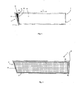
- Fig. 1 shows a longitudinal section of a container device 1 according to the invention in the longitudinal direction L of the container device 1, wherein a bottom plate 2, a front wall 4 and a rear wall 6 and two extending in the longitudinal direction L, opposing side walls 17, 18 (not shown) span the container interior 8.
- a frame-like element 10 is shown in a first position P1.
- the film-like element 12 is folded in the region 14, which is spanned by the front wall 4, the side walls 17, 18 (not shown) and the frame-like element 10 arranged thereon.
- the region 14 is formed such that the folded sheet-like element 12 is completely absorbed by this region 14.
- the frame-like element 10 is here for example in rail-like elements (not shown) in the longitudinal direction L feasible and slidably disposed.
- the guide elements 11 are arranged in the upper region of the frame-like element 10.
- corresponding guide elements can also be arranged in the lower region of the frame-like element in the vicinity of the base plate 2.
- the guide elements 15 are formed complementary to the rail-like elements, not shown, the latter can be arranged both on the bottom plate 2 and on the side walls 17, 18 (not shown).
- Fig. 2 shows a further longitudinal section of the container device 1, in which case the frame-like element 10 is displaced in the longitudinal direction L of the container device 1 and is arranged in its end position P2.
- the frame-like element 10 is lockable and reversibly displaceable in this end position P2.
- Such a lock can be done for example by means of latching, snap or screw mechanism.
- the frame-like element is arranged in this end position P2 adjacent to the movable rear wall 6 of the container device 1 adjacent and spaced, for example by means of sealing elements made of plastic from this.
- the film-like element 12 shown unfolded, so that advantageously the side surfaces 17, 18 (not shown here) and the surface of the front wall 4 and the bottom surface 2 of the container device 1 of the sheet-like element 12, in each case substantially parallel arrangement, are covered.
- the frame-like element 10 is at least partially covered by the film-like element 12.
- rail-like elements For better guidance of the frame-like element 10 and of the sheet-like element 12, preferably two opposing side walls which extend in the longitudinal direction L of the container device 1 according to the invention, rail-like elements (not shown). Such rail-like elements can be arranged both in the vicinity of the bottom plate 2 and in the upper region for opening the container device 1. Furthermore, it would also be conceivable to provide these rail-like elements only additionally or even exclusively only on the base plate 2.
- FIG. 2 shows a cross-section of a container device 1 according to the invention, which represents the container device 1 according to the invention in the starting position P1 of the frame-like element 10.
- the frame-like element 10 has a frame 13, which is supplemented and stabilized by two diagonally arranged struts 15a, 15b. Between the frame 13 and the struts 15a, 15b closable openings 16 of the frame-like element 10 are conditional, through which the load from the salary inside is discharged.
- FIG. 4 a cross section of a container device 1 according to the invention, wherein the film-like element 12 is unfolded and stretched here.
- the film-like element 12 substantially covers both the two side walls 17 and 18 extending in the longitudinal direction L of the container device 1 according to the invention and along the bottom plate 2 and is arranged almost parallel to these surfaces of the container device 1 according to the invention.
- Fig. 5a is a rear view of a container device 1 according to the invention shown, wherein the side walls 17 and 18 and the bottom plate 2 are completed by the frame-like element 10, wherein the frame-like element 10 in this embodiment, a plurality of parts, preferably 5-piece, is formed.
- the container device 1 according to the invention By tilting the container device 1 according to the invention about the pivot axis S, five openings 19 a - e are opened, for example by means of pendulum mechanism, so that that the load through these openings 19 a - e can be removed.
- the rear wall 6 (not shown) hydraulically or pneumatically hinged down or hinged by a further pivot axis T by means of pendulum mechanism.
- the frame-like element 10 which has no opening in this embodiment, but is formed continuously, due to a hinge-like mounting 20 in the transverse direction of the container device 1 according to the invention around the pivot axis T is pendulum.
- an inclined plane is caused, so that the frame-like element 10 opens to remove the load can.
- an extendable and / or fold-out protective element 21 can be arranged on the base plate 2 in order to be able to remove the load in a controlled manner from the container device 1.
- the protective element 21 is formed in the simplest case as Schüttgutabweiser and provided for example of metal or plastic.
- the bottom plate 2 is preferably formed of metal, such as aluminum, steel or a combination thereof.
- the bottom plate 2 of the container device 1 is transferred by the rotation angle ⁇ from the horizontal position into a slope.
- Fig. 5 c the final rear wall 6 of the container device 1 according to the invention is shown, which is formed in the simplest embodiment as a two-part door with a first door leaf 22 and a second door leaf 24.
- both door leaves 22, 24 can be opened laterally outwardly by means of hinge mounting.
- the embodiments mentioned here are not limited thereto, but can be arbitrarily extended depending on the application.
- the frame-like element in the simplest embodiment manually by force in the longitudinal direction L of the container device 1 according to the invention is displaced.
- the frame-like element 10 motorized so that only by pressing a button a corresponding change in position of the frame-like element 10 could be caused.
- a control unit and at least one drive motor are advantageously provided.
- the frame-like member 10 can be moved in any position along the longitudinal axis L.
- the rear wall 6 of the container device 1 is immovable and one of the side walls 17 or 18 is designed to be movable.
- the frame-like element 10 would be arranged displaceably in the transverse direction of the container device 1 in this embodiment.
- Corresponding embodiments of the frame-like element 10 or of the foil-like element 12, as described above, can also be applied to this embodiment.
- the film-like element 12 is designed such that in the deployed state, ie when the frame-like element 10 is in its end position P2, the upwardly directed opening of the container device 1 according to the invention also closes. This is advantageous, in particular if moisture-sensitive cargo is to be transported.
- the film-like element 10, the frame-like element 12 and the rear wall 6 have a common, continuous, closable opening, which is preferably arranged in the region of the bottom plate 2.
- Such an opening is formed for example as a lock and closed by means of slide.
Landscapes
- Engineering & Computer Science (AREA)
- Transportation (AREA)
- Mechanical Engineering (AREA)
- Physics & Mathematics (AREA)
- Thermal Sciences (AREA)
- Health & Medical Sciences (AREA)
- Public Health (AREA)
- Loading Or Unloading Of Vehicles (AREA)
- Packages (AREA)
- Refuse Receptacles (AREA)
Abstract
Description
- Die Erfindung betrifft eine kippbare Behältervorrichtung, insbesondere für den Straßen-, Schienen- und/oder Schiffsverkehr, mit einem Behältergehäuse, welches eine Bodenplatte und wenigstens vier, die Bodenplatte umgebende, Seitenwände aufweist, wodurch durch die Bodenplätte und die Seitenwände ein Behälterinnenraum aufgespannt ist, wobei wenigstens eine Seitenwand beweglich ausgebildet ist. Vorteilhaft ist diese Seitenwand hydraulisch, pneumatisch oder mittels Pendelmechanismus aufklappbar ausgebildet.
- Aus dem bisherigen Stand der Technik sind entsprechende kippbare Behältervorrichtungen bekannt, welche vorwiegend als Auflieger oder als bewegbarer Bestandteil von Lastkraftwagen Verwendung finden. Derartige Behältervorrichtungen sind meist als Container oder Mulden ausgebildet und werden vorwiegend zum Transport von rieselfähigem oder schüttfähigem Material eingesetzt. Bei den Wänden dieser Container sind jeweils zwei Seitenwände einander gegenüberliegend an der Bodenplatte fest angeordnet, wobei die Ausrichtung der Seitenwände beispielsweise vertikal oder schräg in Bezug auf die Bodenplatte ausgebildet ist. Es sind Behältervorrichtungen bekannt, welche wenigstens eine bewegbare Wand aufweisen, welche beispielsweise als Rückwand oder als Seitenwand beweglich ausgebildet ist, so dass in einer aufgerichteten Schräglage der Behältervorrichtung das Transportgut leicht aus dieser heraus gleiten kann.
- Aus Gründen der Stabilität und der Tragfähigkeit sind bekannte Behältervorrichtungen aus Metall ausgebildet und verfügen somit über eine hohe Wärmeleitfähigkeit. Ist die Umgebungstemperatur gering, so kühlt auch die Behältervorrichtung und das darin angeordnete Ladegut schnell aus. Dies wirkt sich besonders nachteilig auf Ladegut aus, welches empfindlich gegenüber Temperaturschwankungen ist. Kühlt ein derartiges Ladegut, wie beispielsweise Kartoffeln oder Zuckerrüben, aus und wird in diesem Zustand abgeladen, besteht die Möglichkeit der Bruch- und Rissbildung, wodurch die Produktqualität signifikant beeinflusst wird. Ferner besteht bei niedriger Umgebungstemperatur während des Transports von Obst und Gemüse die Gefahr, dass das Ladegut an der Behältervorrichtung festfriert und nur teilweise entladbar ist.
- Besonders feinkörniges Ladegut neigt zudem dazu sich in Vertiefungen oder Rillen der Behältervorrichtung abzusetzen und nicht mit entladen zu werden. Dies bedingt einen zusätzlichen Reinigungsschritt vor der erneuten Beladung der Behältervorrichtung.
- Daher ist es Aufgabe der vorliegenden Erfindung, eine kippbare Behältervorrichtung zur Verfügung zu stellen, welche eine bessere Temperaturisolierung im Vergleich zu gängigen Behältervorrichtungen bereitstellt. Zudem liegt der vorliegenden Erfindung die Aufgabe zugrunde, feinkörniges Transportgut nahezu vollständig aus der Behältervorrichtung zu entfernen.
- Diese Aufgabe wird gemäß den Merkmalen des Patentanspruches 1 gelöst. Vorteilhafte Ausführungsformen und Weiterbildungen sind Gegenstand der Unteransprüche.
- Ein wesentlicher Punkt der Erfindung liegt darin, dass ein flexibles, folienartiges Element zumindest teilweise an einem in dem Behälterinnenraum angeordneten rahmenartigen Element angeordnet ist, wobei das rahmenartige Element in wenigstens zwei Positionen entlang einer Achse des Behältergehäuses verschiebbar ist.
- Vorteilhaft dient die Positionsänderung des rahmenartigen Elements entlang einer Achse der Behältervorrichtung zur Positions- sowie zur Formänderung des folienartigen Elements. Im einfachsten Ausführungsfall ist das folienartige Element derart ausgebildet, dass es im aufgefalteten Zustand zumindest die Bodenplatte der Behältervorrichtung flächenmäßig bedeckt und zu dieser im Wesentlichen horizontal, direkt benachbart angeordnet ist. Ferner kann das folienartige Element derart ausgebildet sein, dass es die Bodenplatte sowie wenigstens eine Seitenwand, bevorzugt zwei unbewegliche Seitenwände und meist bevorzugt drei unbewegliche Seitenwände der Behältervorrichtung flächenmäßig überspannt.
- Das folienartige Element ist erfindungsgemäß einteilig ausgebildet und besteht erfindungsgemäß aus einem Material, welches in seiner Materialstärke dünn im Vergleich zu seiner Materialbreite bzw. -länge ausgebildet ist. Bevorzugt weist das folienartige Element eine Materialstärke im Bereich von 0,1 mm- 20 mm auf, besonders bevorzugt im Bereich von 1 mm- 10 mm. Zudem ist das folienartige Element flexibel ausgebildet und ist somit beispielsweise biegsam, verformbar, komprimierbar, aufrollbar oder auch zusammenfaltbar. Die Flexibilität ist vorteilhaft, da nach einer Kraftbeaufschlagung des folienartigen Elementes, beispielsweise in Form einer Zugkraft, dieses im Wesentlichen wieder in seine ursprüngliche Ausgangsposition und Ausgangsform rückführbar ist. Erfindungsgemäß ist das folienartige Element derart dehnbar ausgebildet, dass es unter Zugbeanspruchung um ein Vielfaches dehnbar ist. Die Materialfläche des folienartigen Elements vergrößert sich unter Zugbeanspruchung um wenigstens das Doppelte, bevorzugt um das Vierfache und meist bevorzugt um das Fünf- bis Zehnfache im Vergleich zu der Materialfläche in der Ausgangslage. In der Ausgangslage oder auch Ausgangsposition des folienartigen Elements wirkt auf dieses keine Zugspannung. Bevorzugt wirkt lediglich eine Druckkraft auf das folienartige Element, welche durch das arretierte, rahmenartige Element bedingt wird, um das folienartige Element im zusammengefalteten Zustand zu halten.
- Ferner ist denkbar, dass das folienartige Element wetterfest und/oder wasserabweisend ausgebildet ist. Das folienartige Element kann beispielsweise aus wenigstens einem wasserfesten und/oder wasserabweisenden Material hergestellt oder mit einem solchen beschichtet sein. Dies ist vorteilhaft, da bei nach oben offenen Behältervorrichtungen das folienartige Element der Witterung, wie Regen, Schneefall oder auch hohe Sommertemperaturen, ausgesetzt ist. Der Elastizitätsmodul des folienartigen Elements ist somit bevorzugt unabhängig von Witterungs- und Temperaturbedingungen.
- Darüber hinaus kann das folienartige Element zumindest teilweise, bevorzugt im Bereich der Bodenplatte der Behältervorrichtung, wasserdurchlässig ausgebildet sein. Dies erweist sich als vorteilhaft, sofern das Ladegut in starkem Regen transportiert wird. Regenwasser kann gezielt abfließen, wodurch Staunässe vermieden wird.
- Ferner ist das folienartige Element langlebig ausgebildet, sodass auch nach mehrfacher erfindungsgemäßer Benutzung keine Qualitätseinbußen bedingt werden. Bevorzugt liegen chemische und physikalische Eigenschaften des folienartigen Elements im Wesentlichen unverändert vor. Vorteilhaft ist das folienartige Element reißfest ausgebildet, so dass bei kurzer, starker Kraftbeaufschlagung das folienartige Element intakt bleibt und eine Lochbildung vermieden wird.
- Darüber hinaus ist denkbar, dass das folienartige Element wenigstens eine Materialschicht aufweist, bevorzugt auch mehrlagig ausgebildet ist. Die Materialschichten können hierbei jeweils eine im Wesentlichen gleiche Materialzusammensetzung aufweisen, sich aber selbstverständlich auch in ihrer Materialzusammensetzung und Materialstärke unterscheiden. So ist denkbar, dass mehrer Materialschichten zueinander horizontal oder vertikal angeordnet sind oder auch keine feste Orientierung zueinander aufweisen.
- Ferner ist auch denkbar, dass die dem Behälterinnenraum zugewandten Flächen des folienartigen Elements, also diejenigen Flächen, welche mit dem Ladegut in direktem Kontakt stehen, beschichtet sind, beispielsweise antiseptisch oder antibakteriell, sodass Pilz-, Bakterien- oder Keimwachstum reduziert bzw. gänzlich verhindert wird. Derartige Beschichtungen können beispielsweise mittels metallischem Silber vorgesehen sein. Selbstverständlich ist die Art der Beschichtung nicht auf die hier beschriebenen Beispiele beschränkt, sondern kann weiter gefasst verstanden werden. So sind darüber hinaus auch Beschichtungen mit verbessertem Gleitwert denkbar, welche die Be- und Entladung der Behältervorrichtung signifikant vereinfachen, da durch die Reduzierung der Reibung das Ladegut einfacher und schneller entnommen werden kann.
- Vorteilhaft ist das folienartige Element zumindest teilweise an einem rahmenartigen Element angeordnet. Das rahmenartige Element ist vorteilhaft den Abmessungen des Behälterinnenraumes angepasst, sodass das rahmenartige Element passgenau in den Behälterinnenraum anordbar und bewegbar ist. Vorteilhaft ist das rahmenartige Element aus Metall, Leichtmetall, wie beispielsweise Aluminium, oder Kunststoff bzw. Verbundwerkstoffen hergestellt. Je nach Bedarf kann das rahmenartige Element aus zylindrischen Bauteilen, rohrförmigen Bauteilen mit variierendem Querschnitt, beispielsweise rund oder eckig, oder auch aus Massivbauteilen oder einer Mischung daraus ausgebildet sein. Das rahmenartige Element ist vorteilhaft zwischen zwei sich gegenüberliegenden Seitenwänden der Behältervorrichtung angeordnet, wobei eine der Seitenwände beweglich, bevorzugt aufklappbar, ausgebildet ist. So kann das rahmenartige Element beispielsweise zwischen den die Längsrichtung der Behältervorrichtung begrenzenden Seitenwänden, also Vorder- und Rückwand der Behältervorrichtung angeordnet und auch in Längsrichtung der Behältervorrichtung verschiebbar sein. Ferner ist denkbar, dass das rahmenartige Element zwischen den beiden sich in Längsrichtung der Behältervorrichtung erstreckenden Seitenwänden angeordnet ist und senkrecht zur Längsrichtung der Behältervorrichtung verschiebbar angeordnet ist.
- Das rahmenartige Element ist vorteilhaft in wenigstens zwei Positionen entlang einer Achse der Behältervorrichtung verschiebbar anordbar. Bevorzugt erfolgt diese Bewegung entlang der Längsachse bzw. der Querachse der Behältervorrichtung. Unter der Längsachse ist hierbei die Achse zu verstehen, welche sich in Längsrichtung der Behältervorrichtung erstreckt, also in der Richtung, in welcher die Behältervorrichtung ihre größte geometrische Ausdehnung aufweist. Unter der Querachse ist die Achse zu verstehen, welche senkrecht zur Längsachse der Behältervorrichtung angeordnet ist und welche in der Ausgangslage der Behältervorrichtung mit der Längsachse eine horizontal angeordnete Ebene aufspannt. Als Ausgangslage der Behältervorrichtung ist hierbei die im Wesentlichen horizontale Ausrichtung der Bodenplatte der Behältervorrichtung zu verstehen, wie beispielsweise während des Beladens der Behältervorrichtung oder des Transports des Ladeguts. Zum Entladen hingegen erfolgt eine Verkippung der Behältervorrichtung, so dass die Bodenplatte, auch Kippbrücke genannt, von ihrer im Wesentlichen horizontalen Ausrichtung ausgelenkt wird und eine schiefe Ebene bildet. Die Kippbewegung kann hierbei beispielsweise entlang einer Schwenkachse in Längsrichtung (Querrichtung) der Behältervorrichtung, so dass ein seitliches (rückwärtiges) Entladen ermöglicht wird.
- Eine erste Position des rahmenartigen Elements ist als dessen Ausgangslage zu verstehen, wobei das folienartige Element, welches an dem rahmenartigen Element zumindest teilweise und lösbar angeordnet ist, zusammengefaltet oder auch komprimiert ebenfalls in seiner Ausgangslage vorliegt. Durch Kraftbeaufschlagung des rahmenartigen Elementes, beispielsweise in Längsrichtung der Behältervorrichtung, werden dieses sowie das daran zumindest teilweise angeordnete folienartige Element aus der Ausgangslage ausgelenkt. Das folienartige Element erfährt somit ebenfalls eine Kraftbeaufschlagung und wird auseinander gefaltet bzw. aufgefaltet. Dies erfolgt bevorzugt derart, dass das folienartige Element den Behälterinnenraum zumindest teilweise, bevorzugt nahezu gänzlich abdeckt, sodass bevorzugt drei nichtbewegbare Seitenwände und Bodenplatte flächig abgedeckt werden. Bevorzugt ist das rahmenartige Element in seiner Ausgangslage arretierbar.
- Als zweite Position des rahmenartigen Elements ist im einfachsten Fall die Endposition zu verstehen, in welcher keine weitere Bewegung des rahmenartigen Elements in der bisherigen Verschiebungsrichtung mehr möglich ist. In dieser Endposition des rahmenartigen Elements ist das flexible folienartige Element beispielsweise in Längsrichtung der Behältervorrichtung mit einer Zugkraft beaufschlagt. Das folienartige Element liegt in diesem Fall gänzlich aufgefaltet, beispielsweise in einer nach oben geöffneten u-Form vor. Dies ist vorteilhaft, da das folienartige Element somit im Wesentlichen parallel zu der Bodenplatte und zu den Seitenwänden der Behältervorrichtung angeordnet ist, so dass das Volumen des Behälterinnenraums nahezu unverändert vorliegt. Durch diese Kraftbeaufschlagung des folienartigen Elementes wird eine Reduzierung der Faltenbildung des Materials bedingt, sodass eine leichte Be- und Entladung möglich ist, ohne das folienartige Element zu beschädigen und zu zerstören, bzw. um auch feinkörniges Ladegut, wie beispielsweise Getreide, vollständig aus dem Behälterinnenraum entfernen zu können.
- Das rahmenartige Element ist vorteilhaft in mehr als zwei Positionen entlang einer Achse, beispielsweise Längsachse und/oder Querachse, der Behältervorrichtung verschiebbar angeordnet. Bevorzugt erfolgt die Verschiebung stufenlos. Es ist jedoch auch denkbar, dass das rahmenartige Element lediglich in vorbestimmbaren Positionen verschiebbar angeordnet ist. Dies ist je nach Anwendungsfall beliebig wähl- und kombinierbar. In jeder vorbestimmbaren Position ist das rahmenartige Element arretierbar, so dass das rahmenartige Element auch als Trennelement dienen kann, um den Behälterinnenraum der Behältervorrichtung zu unterteilen. Bevorzugt ist das rahmenartige Element als Ladetrennwand ausgebildet. Dies ist vorteilhaft, da somit temperaturempfindliches und temperaturunempfindliches Ladegut zeitgleich in nur einer Behäitervorrichtung transportiert werden kann.
- Vorteilhaft ist die Anordnung des folienartigen Elements, bedingt durch die Positionsänderung des rahmenartigen Elements, reversibel ausgebildet. Wird das rahmenartige Element von der zweiten Position wieder in seine Ausgangsposition rückgeführt, so bedingt die flexible, elastische Ausbildung des folienartigen Elements ebenfalls dessen Relaxation und Rückführung in seine Ausgangslage. So kann das folienartige Element schnell und einfach verstaut werden.
- Denkbar ist ferner auch, dass das folienartige Element zusätzliche Spannelemente aufweist, welche im einfachsten Ausführungsfall an der den Seitenwänden und der Bodenplatte zugewandten Elementflächen fest oder auch lösbar angeordnet sind, sodass nach Beendigung der Zugspannungsbeaufschlagung das folienartige Element schnell und zerstörungsfrei in seine ursprüngliche Ausgangsposition rückführbar ist, ohne dass Verklemmungen oder Beschädigungen bedingt werden. Denkbar wäre hierbei beispielsweise, dass eine Vielzahl derartiger Spannelemente an dem folienartigen Element in Bewegungsrichtung der Behältervorrichtung angeordnet sind und beispielsweise aufgeklebt, zumindest teilweise an dem folienartigen Element fixiert oder durch Aussparungen des folienartigen Element in dessen Randbereichen durchführbar sind. Wird die Kraftbeaufschlagung auf das folienartige Element unterbrochen, bedingen die Spannelemente eine zugspannungsbedingte Faltenbildung und das folienartige Element faltet sich selbstständig in seine Ausgangslage zusammen.
- Ferner ist auch denkbar, dass derartige Spannelemente direkt in das folienartige Element integriert sind und beispielsweise als Abschnitte mit einer höheren Rückführungskraft ausgebildet sind.
- Wird das folienartige Element in der Behältervorrichtung nicht mehr benötigt, so wird zunächst die Arretierung des rahmenartigen Elements gelöst, so dass dieses entlang wenigstens einer Achse der Behältervorrichtung, bevorzugt der Längs- oder Querachse, frei verschiebbar wird. Das rahmenartige Element wird anschließend in seine Ausgangslage zurückgeführt und dort ebenfalls arretiert. Während dieses Rückführungsprozesses ist sicherzustellen, dass auch das folienartige Element zerstörungsfrei in seine Ausgangslage rückgeführt wird. Beschädigungen durch Verklemmen sind zu vermeiden. Dies wird beispielsweise mittels Spanngurten gelöst.
- Ferner sind auch seil- bzw. bandähnliche Spannelemente denkbar, welche bei Rückführung des rahmenartigen Elements das folienartige Element bevorzugt vertikal anheben, so dass zwischen Bodenplatte und folienartigem Element ein Freiraum bedingt wird. Hierzu sind derartige Spannelemente im Bodenbereich des rahmenartigen Elements bevorzugt fest angeordnet, wobei eine Aufrolleinrichtung der Spannelemente im unteren Bereich der dem rahmenartigen Element zugewandten, gegenüberliegenden Seitenwand der Behältervorrichtung angeordnet ist.
- Befindet sich das rahmenartige Element in einer arretierten Position, so liegen die Spannelemente bevorzugt spannungsfrei vor. Wird das rahmenartige Element in seiner Ausgangslage rückgeführt, so wird bevorzugt automatisch der Aufrollmechanismus gestartet und die Spannelemente werden gespannt. Durch diesen Spannungsprozess wird das folienartige Element von der Bodenplatte der Behältervorrichtung vertikal angehoben und kann sich während der gesamten Rückführung nicht mehr verklemmen. Selbstverständlich ist der Erfindungsgegenstand nicht hierauf begrenzt sondern beliebig erweiterbar.
- Bei einer weiteren vorteilhaften Ausführungsform ist das folienartige Element entnehmbar angeordnet. Erfindungsgemäß ist das folienartige Element von dem rahmenartigen Element und bevorzugt ebenfalls von der dem rahmenartigen Element gegenüberliegenden unbeweglichen Seitenwand lösbar angeordnet. Dies ist besonders vorteilhaft für die Wartung, die Reparatur und die Reinigung der Behältervorrichtung und auch des folienartigen Elementes selbst. Die lösbare Befestigung des folienartigen Elements an der dem rahmenartigen Element gegenüberliegenden unbeweglichen Seitenwand ist vorteilhaft, da bei der durch die Positionsänderung des rahmenartigen Elements bedingte Zugbeanspruchung eine elastische Dehnung des folienartigen Elements bedingt wird. Vorteilhaft ist das folienartige Element im unteren Bereich dieser Seitenwand, also in Nähe der Bodenplatte, und im oberen Bereich dieser Seitenwand lösbar angeordnet. Selbstverständlich ist die lösbare Fixierung nicht auf diese Bereiche der Seitenwand beschränkt sondern beliebig erweiterbar. Bevorzugt erfolgt die lösbare Fixierung des folienartigen Elements an der Seitenwand mit bekannten Mitteln, wie beispielsweise Verkleben oder Verspannen, auch unter zu Hilfenahme von Führungsschienen oder Spannösen. Die genannten Beispiele dienen lediglich der Veranschaulichung und sind nicht darauf beschränkt.
- Selbstverständlich kann auch die dem rahmenartigen Element gegenüberliegende Seitenwand, an welcher das folienartige Element lösbar fixiert ist, beweglich ausgebildet sein.
- Bei einer weiteren vorteilhaften Ausführungsform ist das folienartige Element aus einem Material ausgebildet, welches aus einer Gruppe von Materialien ausgewählt ist, welche Kunststoffe, Verbundwerkstoffe, faserverstärkte Kunststoffe und/oder Textilien enthält. Als Kunststoffe werden hierbei bevorzugt Elastomere verwendet, da durch deren flexible Eigenschaften nach Beendigung der Kraftbeaufschlagung eine Rückführung des folienartigen Elementes in seine Ausgangsposition und -form bedingt wird. Bei der Verwendung von Verbundwerkstoffen oder faserverstärkten Kunststoffen sind besondere Materialeigenschaften, wie beispielsweise Dehnbarkeit, Belastbarkeit, Temperaturbeständigkeit oder Druckbeständigkeit wichtig. So ist das folienartige Element aus einem elastischen Material ausgebildet, welches unter Kraftbeaufschlagung einen hohen Druck sowie starke Temperaturschwankungen, bevorzugt im Bereich von -40°C bis 80°C, standhält, ohne dass die Dehnbarkeit beeinflusst wird.
- Ferner können für das folienartige Element auch jegliche Art von Textilien eingesetzt werden, welche beispielsweise auch imprägniert oder vorbehandelt vorliegen, sodass sie den Ansprüchen der Erfindung genügen. So wäre denkbar, dass ein Verbundmaterial aus Kunststoff und Textilmaterial verwendet wird, wobei das Textilmaterial der Verstärkung dient. Hierbei kann das Textilmaterial auch nur abschnittsweise in dem folienartigen Element angeordnet sein, beispielsweise um das folienartige Element in den Fixierungsbereichen zu verstärken.
- Bei einer weiteren vorteilhaften Ausführungsform ist das folienartige Element als Thermoisolationsbarriere ausgebildet. Dies ist besonders vorteilhaft, wenn es sich bei dem Transportgut um temperaturempfindliche Materialien handelt, deren Qualität durch die starken Temperaturschwankungen der meist metallisch ausgebildeten Behältervorrichtung verschlechtert wird und eine Isolierung bedingen. Im einfachsten Ausführungsbeispiel ist das folienartige Element vollständig als Thermoisolationsbarriere ausgebildet, so dass das Transportgut kältebrückenfrei transportiert werden kann, ohne beispielsweise an der Behältervorrichtung anzufrieren. Ferner wäre auch denkbar, dass das folienartige Element eine zusätzliche Beschichtung bzw. Lage aufweist, welche thermoisolierende Eigenschaften aufweist. Hierzu kann es beispielsweise von Vorteil sein, dass die Flächen des folienartigen Elementes einseitig und/oder beidseitig beschichtet vorliegen.
- Bei einer weiteren vorteilhaften Ausführungsform ist das rahmenartige Element in Längsrichtung des Behälterinnenraums in wenigstens einer ersten Position als Ausgangsposition und einer zweiten Position verschiebbar angeordnet. Dies ist vorteilhaft, da somit das an dem rahmenartigen Element zumindest teilweise befestigte folienartige Element in der Ausgangsposition zusammengefaltet vorliegt. Vorteilhaft ist hierbei das folienartige Element an einer dem rahmenartigen Element gegenüberliegend angeordneten Seitenfläche der Behältervorrichtung lösbar fixiert, wobei diese Seitenwand eine von vertikal verschieden ausgebildeten Ausrichtung und bevorzugt eine zu dem rahmenartigen Element hin verlaufende, abnehmende Schräge aufweist. Bevorzugt ist diese Seitenwand als Vorderwand oder Bordwand ausgebildet, welche unmittelbar zu der Fahrerkabine des LKWs ausgerichtet ist, sofern die erfindungsgemäße kippbare Behältervorrichtung als Auflieger oder Aufbau für LKWs vorgesehen ist.
- Das rahmenartige Element ist in seiner ersten Position somit vorteilhaft an der unteren Kante der Schräge der Seitenwand angeordnet, sodass die Seitenwand mit dem rahmenartigen Element ein sich nach oben erweiterndes Raumvolumen aufspannt, welches zudem von den sich in Längsrichtung der Behältervorrichtung erstreckenden beiden Seitenwänden zumindest teilweise begrenzt wird. Erfindungsgemäß wird das folienartige Element Im zusammengefalteten Zustand seine Ausgangslage in diesem freien Volumen angeordnet.
- Durch Kraftbeaufschlagung des rahmenartigen Elements in einer Bewegungsrichtung entlang einer Achse der Behältervorrichtung, beispielsweise entlang der Längsachse, also von der bevorzugt unbeweglichen Vorderwand weg, wird das rahmenartige Element und zugleich auch das daran befestigte folienartige Element aus seiner Ausgangsposition ausgelenkt und in wenigstens eine weitere, zweite Position verschoben. Durch die Fixierung des folienartigen Elementes an der dem rahmenartigen Element gegenüberliegenden bevorzugt unbeweglichen Seitenwand der Behältervorrichtung wird durch die Verschlebung des rahmenartigen Elementes das folienartige Element ebenfalls aufgefaltet und aufgespannt. Diese Seitenwand ist beispielsweise als Vorderwand quer zur Längsrichtung der Behältervorrichtung ausgebildet und erfindungsgemäß zumindest teilweise, bevorzugt im Wesentlichen vollständig, von einem Abschnitt des folienartigen Elements überspannt bzw. bedeckt.
- Vorteilhaft ist das folienartige Element an dem rahmenartigen Element durch Laschen fixiert, wobei die Fixierung sowohl an der Oberseite und/oder der Unterseite des rahmenartigen Elements erfolgt. Bevorzugt ist das folienartige Element umlaufend an dem rahmenartigen Element angeordnet, so dass kein Freiraum bedingt wird, durch welchen Ladegut austreten kann. Zudem ist das folienartige Element auch an der dem rahmenartigen Element gegenüberliegenden Seitenwand des Behälterinnenraumes derart fixiert, sodass bevorzugt mehrere Fixierungspunkte über die Fläche dieser Seitenwand angeordnet sind. Vorteilhaft ist das folienartige Element auch von dieser Seitenwand lösbar ausgebildet, beispielsweise verhakbar oder verklemmbar.
- Bei einer weiteren vorteilhaften Ausführungsform ist das rahmenartige Element mittels schienenartiger Elemente, welche zumindest teilweise an einer der Seitenwände, bevorzugt an zwei sich gegenüberliegenden Seitenwänden, welche sich in Längsrichtung der Behältervorrichtung erstrecken, fixiert sind, verschiebbar ausgebildet. Dies ist vorteilhaft, da die schienenartigen Elemente als Führung des rahmenartigen Elementes während dessen Verschiebung dienen. Somit kann eine leichte, kraftsparende Positionsveränderung des rahmenartigen Elements erzeugt werden. Als schienenartige Elemente können beispielsweise Leisten, Nuten, Schraubgewinde oder auch Rollen verstanden werden, sofern sich diese eignen, das rahmenartige Element in seiner Position unterschiedlich anzuordnen. Vorteilhaft ist auch das folienartige Element an diesen schienenartigen Elementen lösbar fixiert, sodass auch die Führung des folienartigen Elementes, beispielsweise mittels Rollen, ermöglicht wird. Somit wird das Aufspannen des folienartigen Elementes vereinfacht. Die Positionsänderung des rahmenartigen Elements kann manuell oder auch maschinell erfolgen.
- Darüber hinaus ist denkbar, dass die schienenartigen Elemente einen Laufschutz aufweisen, sodass die schienenartigen Elemente weder durch Ladegut, folienartiges Element oder Verunreinigungen blockiert werden und nicht mehr funktionstüchtig sind.
- Vorteilhaft ist auch denkbar, die schienenartigen Elemente an zwei sich gegenüberliegenden Seitenwänden anzuordnen, bevorzugt im unteren Bereich, benachbart zu der Bodenplatte oder auch im oberen Bereich der Seitenwände zur Öffnung der Behältervorrichtung hin. Vorteilhaft sind die schienenartigen Elemente an beiden Seitenwänden auf gleicher Höhe und parallel zueinander angeordnet, sodass das Verschieben des rahmenartigen Elementes und des folienartigen Elementes ermöglicht werden.
- Bei einer weiteren vorteilhaften Ausführungsform weist das rahmenartige Element wenigstens eine Öffnung auf. Bevorzugt weist das folienartige Element ebenfalls eine Öffnung auf, welche zu der Öffnung des rahmenartigen Elements direkt benachbart angeordnet ist. Dies ist vorteilhaft, da durch diese Öffnung das Ladegut aus dem Behälterinnenraum ausgeführt werden kann. So ist beispielsweise denkbar, dass die Rückwand beispielsweise durch Entriegeln, durch Aufkippen der Behältervorrichtung oder mittels Pendelmechanismus geöffnet werden kann. Vorteilhaft ist das rahmenartige Element entlang wenigstens einer Achse der Behältervorrichtung derart verschiebbar, bis es direkt benachbart zu der Rückwand anordbar und arretierbar ist. Die Rückwand ist der Vorderwand gegenüberliegend angeordnet und im geschlossenen Zustand vertikal ausgerichtet, wobei das rahmenartige Element erfindungsgemäß zwischen der Vorder- und Rückwand der Behältervorrichtung bewegbar angeordnet ist.
- Ferner ist denkbar, dass das rahmenartige Element Verstrebungen, beispielsweise in Form von Längs- und/oder Querstreben aufweist, welche vorteilhaft das Zusammenfalten des folienartigen Elementes vereinfachen. Zudem sind derartige Verstrebungen auch vorteilhaft, um das folienartige Element in seiner Ausgangslage, also im zusammengefalteten Zustand, zu fixieren. Derartige Verstrebungen sind fest mit dem rahmenartigen Element verbunden, beispielsweise verklebt oder verschweißt. Es ist auch denkbar, dass die Verstrebungen lösbar vom rahmenartigen Element, beispielsweise mittel Klick- oder Schraubmechanismus, angeordnet sind, so dass in Abhängigkeit des Ladeguts die Verstrebung austauschbar ist.
- Ferner sind aber auch mehrere Öffnungen des rahmenartigen Elements denkbar, welche nicht auf spezielle geometrische Ausführungen beschränkt sind.
- Bei einer weiteren vorteilhaften Ausführungsform ist das folienartige Element an dem rahmenartigen Element lösbar angeordnet und das folienartige Element weist wenigstens eine Aussparung auf, welche im Wesentlichen deckungsgleich mit der wenigstens einen Öffnung des rahmenartigen Elements ausgebildet ist, sodass der Behälterinnenraum durch beide Öffnungen zugänglich ist. Dies ist vorteilhaft, da somit eine durchgängige Öffnung geschaffen wird, um das Ladegut aus dem Behälterinnenraum sowohl aus dem folienartigen Element als auch durch das rahmenartige Element aus dem Behälterinnenraum hinauszubefördern.
- Bei einer weiteren vorteilhaften Ausführungsform ist wenigstens ein Verschließelement zum Verschließen der wenigstens einen Öffnung des rahmenartigen Elements beweglich ausgebildet. Dies ist vorteilhaft, da somit beim Transport des Ladeguts keine Ladung aus dem Behälterinnenraum aus dem durch das folienartige Element aufgespannten Behälterinnenraum austreten kann. Ferner dient das Verschließelement in der Ausgangsposition des rahmenartigen Elements auch dem Schutz des zusammengefalteten folienartigen Elements, wenn dieses nicht benutzt wird. Das Verschließelement kann beispielsweise als Einfach- oder Doppeltür ausgebildet sein oder auch als einklickbare, einspannbare oder eindrehbare Platte.
- Bei einer weiteren vorteilhaften Ausführungsform weist das Verschließelement eine Verkleidung auf. Vorteilhaft ist diese Verkleidung zu dem Behälterinnenraum hin ausgebildet und verhindert das Einklemmen oder Beschädigen des folienartigen Elements.
- Darüber hinaus ist denkbar, dass das folienartige Element schalldämmend ausgebildet ist. Dies ist vorteilhaft, da sowohl bei Lade- als auch bei Entladevorgang der Behältervorrichtung Lärm in Form von Schallwellen bedingt wird, welche durch das folienartige Element zumindest teilweise absorbiert werden.
- Selbstverständlich ist die erfindungsgemäße Vorrichtung nicht auf die genannten Beispiele beschränkt, sondern beliebig erweiterbar. So ist beispielsweise denkbar, dass die erfindungsgemäße Behältervorrichtung bei Kippaufbauten, Kippanhängern oder Kippsattelaufliegern, wie beispielsweise Hinterkippmulden, Halbrundmulden oder Kastenmulden, Verwendung findet.
- Ferner besteht auch die Möglichkeit die erfindungsgemäße Behältervorrichtung anstelle bei LKWs für kippbare Güterwagons vorzusehen.
- Weitere vorteilhafte Ausführungsformen ergeben sich aus den beigefügten Zeichnungen.
- Darin zeigen:
- Fig. 1
- einen Längsschnitt der erfindungsgemäßen Behältervorrichtung;
- Fig. 2
- einen weiteren Längsschnitt der erfindungsgemäßen Behältervorrichtung;
- Fig. 3
- einen Querschnitt einer erfindungsgemäßen Behältervorrichtung;
- Fig. 4
- einen weiteren Querschnitt einer erfindungsgemäßen Behältervorrichtung mit einem folienartigen Element; und
- Fig. 5 a -c
- eine Rückansicht einer Seitenwand einer erfindungsgemäßen Behältervorrichtung;
-
Fig. 1 zeigt einen Längsschnitt einer erfindungsgemäßen Behältervorrichtung 1 in Längsrichtung L der Behältervorrichtung 1, wobei eine Bodenplatte 2, eine Vorderwand 4 und eine Rückwand 6 sowie zwei sich in Längsrichtung L erstreckenden, einander gegenüber liegende Seitenwände 17, 18 (nicht gezeigt) den Behälterinnenraum 8 aufspannen. - Innerhalb dieses Behälterinnenraumes 8 ist ein rahmenartiges Element 10 in einer ersten Position P1 dargestellt. In dieser Ausgangsposition P1 des rahmenartigen Elementes 10 ist das folienartige Element 12 zusammengefaltet in dem Bereich 14 angeordnet, welcher von der Vorderwand 4, den daran angeordneten Seitenwänden 17, 18 (nicht gezeigt) sowie dem rahmenartigen Element 10 aufgespannt wird. Vorteilhaft ist der Bereich 14 derart ausgebildet, dass das zusammengefaltete folienartige Element 12 von diesem Bereich 14 vollständig aufgenommen wird. Mittels Führungselementen 11 ist das rahmenartige Element 10 hier beispielhaft in schienenartigen Elementen (nicht gezeigt) in Längsrichtung L führbar und verschiebbar angeordnet. In diesem Ausführungsbeispiel sind die Führungselemente 11 im oberen Bereich des rahmenartigen Elements 10 angeordnet. Vorteilhaft können entsprechende Führungselemente auch im unteren Bereich des rahmenartigen Elements in der Nähe der Bodenplatte 2 angeordnet sein. Bevorzugt sind die Führungselemente 15 komplementär zu den nicht gezeigten schienenartigen Elementen ausgebildet, wobei letztere sowohl an der Bodenplatte 2 als auch an den Seitenwänden 17, 18 (nicht gezeigt) angeordnet sein können. In
Fig. 2 wird ein weiterer Längsschnitt der Behältervorrichtung 1 gezeigt, wobei hier das rahmenartige Element 10 in Längsrichtung L der Behältervorrichtung 1 verschoben ist und in seiner Endposition P2 angeordnet ist. Vorteilhaft ist das rahmenartige Element 10 in dieser Endposition P2 arretierbar und reversibel verschiebbar. Eine derartige Arretierung kann beispielsweise mittels Rast-, Schnapp- oder auch Schraubmechanismus erfolgen. Vorteilhaft ist das rahmenartige Element in dieser Endposition P2 direkt zu der beweglich ausgebildeten Rückwand 6 der Behältervorrichtung 1 benachbart angeordnet und beispielsweise mittels Dichtelementen aus Kunststoff vom dieser beabstandet. - In dem in
Fig. 2 dargestellten Längsschnitt der erfindungsgemäßen Behältervorrichtung 1 ist das folienartige Element 12 entfaltet dargestellt, sodass vorteilhaft die Seitenflächen 17, 18 (hier nicht gezeigt) sowie die Fläche der Vorderwand 4 als auch die Bodenfläche 2 der Behältervorrichtung 1 von dem folienartigen Element 12, in im Wesentlichen jeweils paralleler Anordnung, bedeckt sind. Vorteilhaft ist das rahmenartige Element 10 zumindest teilweise von dem folienartigen Element 12 überdeckt. - Zur besseren Führung des rahmenartigen Elements 10 sowie des folienartigen Elements 12 weisen bevorzugt zwei sich gegenüber liegende Seitenwände, welche sich in Längsrichtung L der erfindungsgemäßen Behältervorrichtung 1 erstrecken, schienenartige Elemente auf (nicht gezeigt). Derartige schienenartige Elemente können sowohl in der Nähe der Bodenplatte 2 als auch im oberen Bereich zur Öffnung der Behältervorrichtung 1 angeordnet sein. Ferner wäre auch denkbar, diese schienenartigen Elemente lediglich zusätzlich auf oder auch ausschließlich nur auf der Bodenplatte 2 vorzusehen.
- In
Fig. 3 ist ein Querschnitt einer erfindungsgemäßen Behältervorrichtung 1 gezeigt, welcher die erfindungsgemäße Behältervorrichtung 1 in der Ausgangsposition P1 des rahmenartigen Elements 10 darstellt. Das rahmenartige Element 10 weist einen Rahmen 13 auf, welcher durch zwei diagonal angeordnete Verstrebungen 15a, 15b ergänzt und stabilisiert wird. Zwischen dem Rahmen 13 und den Verstrebungen 15a, 15b werden verschließbare Öffnungen 16 des rahmenartigen Elements 10 bedingt, durch welche das Ladegut aus dem Gehälterinnenraum abführbar ist. - Im Vergleich hierzu zeigt
Fig. 4 einen Querschnitt einer erfindungsgemäßen Behältervorrichtung 1, wobei das folienartige Element 12 hierbei entfaltet und gespannt vorliegt. AusFig. 4 wird ersichtlich, dass das folienartige Element 12 sowohl die beiden sich in Längsrichtung L der erfindungsgemäßen Behältervorrichtung 1 erstreckenden Seitenwände 17 und 18 sowie entlang der Bodenplatte 2 diese im Wesentlichen bedecken und nahezu parallel zu diesen Flächen der erfindungsgemäßen Behältervorrichtung 1 angeordnet ist. - Durch Beaufschlagung des folienartigen Elementes 12 mit Zugspannung wird eine Faltenbildung verhindert, sodass dass das Ladegut unproblematisch be- und entladen werden kann. Unter Zugspannung ist eine derartige Kraft zu verstehen, unter welcher das folienartige Element 12 intakt bleibt, gespannt vorliegt und nicht überdehnt wird, sodass die Elastizität des folienartigen Elements dieses weiterhin nach Beendigung der Kraftbeaufschlagung in seine ursprüngliche Form und auch Ausgangslage zurückführt.
- In
Fig. 5a ist eine Rückansicht einer erfindungsgemäßen Behältervorrichtung 1 gezeigt, wobei die Seitenwände 17 und 18 sowie die Bodenplatte 2 von dem rahmenartigen Element 10 abgeschlossen werden, wobei das rahmenartige Element 10 in diesem Ausführungsbeispiel mehrteilig, bevorzugt 5-teilig, ausgebildet ist. Durch Verkippung der erfindungsgemäßen Behältervorrichtung 1 um die Schwenkachse S werden, beispielsweise mittels Pendelmechanismus, fünf Öffnungen 19 a - e geöffnet, sodass dass das Ladegut durch diese Öffnungen 19 a - e entnommen werden kann. Vorteilhaft ist hierbei die Rückwand 6 (nicht gezeigt) hydraulisch oder pneumatisch nach unten aufklappbar bzw. mittels Pendelmechanismus um eine weitere Schwenkachse T aufklappbar. - Ferner wäre auch denkbar, wie in
Fig. 5 b dargestellt, dass das rahmenartige Element 10, welches in diesem Ausführungsbeispiel keine Öffnung aufweist, sondern durchgängig ausgebildet ist, aufgrund einer gelenkartigen Lagerung 20 in Querrichtung der erfindungsgemäßen Behältervorrichtung 1 um die Schwenkachse T pendelbar ist. Durch Verkippung der Behältervorrichtung 1 wird eine schräge Ebene bedingt, so dass sich das rahmenartige Element 10 öffnet, um das Ladegut entfernen zu können. Bevorzugt kann an der Bodenplatte 2 ein ausfahrbares und/oder ausklappbares Schutzelement 21 angeordnet sein, um das Ladegut kontrollierter aus der Behältervorrichtung 1 entfernen zu können. Das Schutzelement 21 ist im einfachsten Fall als Schüttgutabweiser ausgebildet und beispielsweise aus Metal oder Kunststoff vorgesehen. - Die Bodenplatte 2 ist bevorzugt aus Metall, wie beispielsweise Aluminium, Stahl oder einer Kombination hieraus ausgebildet. Über einen Kippmechanismus um die Schwenkachse S ist die Bodenplatte 2 der Behältervorrichtung 1 mit dem Fahrgestell 23, beispielweise eines LKWs oder eines LKW-Anhängers, in Verbindung. Je nach Ladegut wird die Behältervorrichtung 1 um den Drehwinkel α von der horizontalen Position in eine Schräge überführt.
- In
Fig. 5 c ist die abschließende Rückwand 6 der erfindungsgemäßen Behältervorrichtung 1 dargestellt, welche im einfachsten Ausführungsbeispiel als eine zweiteilige Tür mit einem ersten Türflügel 22 und einem zweiten Türflügel 24 ausgebildet ist. Vorteilhaft lassen sich beide Türflügel 22, 24 manuell mittels Scharnierlagerung seitlich nach außen öffnen. - Selbstverständlich sind die hier genannten Ausführungsbeispiele nicht darauf begrenzt, sondern können je nach Anwendungsfall beliebig erweitert werden. So ist beispielsweise auch denkbar, dass das rahmenartige Element im einfachsten Ausführungsbeispiel manuell durch Kraftbeaufschlagung in Längsrichtung L der erfindungsgemäßen Behältervorrichtung 1 verschiebbar ist. Ferner wäre jedoch auch denkbar, das rahmenartige Element 10 motorisiert vorzusehen, sodass lediglich per Knopfdruck eine entsprechende Positionsänderung des rahmenartigen Elements 10 bedingt werden könnte. Hierzu sind vorteilhaft eine Steuerungseinheit sowie wenigstens ein Antriebsmotor vorgesehen. Somit kann das rahmenartige Element 10 in beliebiger Position entlang der Längsachse L verschoben werden.
- Darüber hinaus wäre auch denkbar, dass die Rückwand 6 der Behältervorrichtung 1 unbeweglich ausgebildet ist und eine der Seitenwände 17 oder 18 bewegbar ausgebildet ist. Das rahmenartige Element 10 wäre in diesem Ausführungsbeispiel in Querrichtung der Behältervorrichtung 1 verschiebbar angeordnet. Entsprechende Ausbildungen des rahmenartigen Elements 10 bzw. des folienartigen Elements 12, wie oben beschrieben, sind auch auf die diese Ausführungsform übertragbar.
- Ferner ist denkbar, dass das folienartige Element 12 derart ausgebildet ist, dass es im entfalteten Zustand, also wenn sich das rahmenartige Element 10 in seiner Endposition P2 befindet, die nach oben gerichtete Öffnung der erfindungsgemäßen Behältervorrichtung 1 ebenfalls schließt. Dies ist vorteilhaft, insbesondere wenn feuchtigkeitsempflindliches Ladegut transportiert werden soll.
- Zudem ist denkbar, dass das folienartige Element 10, das rahmenartige Element 12 sowie die Rückwand 6 eine gemeinsame, durchgängige, verschließbare Öffnung aufweisen, welche bevorzugt im Bereich der Bodenplatte 2 angeordnet ist. Eine derartige Öffnung ist beispielsweise als Schleuse ausgebildet und mittels Schieber verschließbar.
- Sämtliche in den Anmeldungsunterlagen offenbarte Merkmale werden als erfindungswesentlich beansprucht, sofern sie einzeln oder in Kombination gegenüber dem Stand der Technik neu sind.
-
- 1
- Behältervorrichtung
- 2
- Bodenplatte
- 4
- Vorderwand
- 6
- Rückwand
- 8
- Behälterinnenraum
- 10
- rahmenartiges Element
- 11
- führungsartiges Element
- 12
- folienartiges Element
- 13
- Rahmen
- 14
- Bereich
- 15a, b
- Verstrebungen
- 16
- Öffnungen des rahmenartigen Elements
- 17, 18
- Seitenflächen
- 19a-e
- weitere Öffnungen des rahmenartigen Elements
- 20
- Lagerung
- 21
- Schüttgutabweiser
- 22
- erster Türflügel
- 23
- Fahrgestell
- 24
- zweiter Türflügel
- P1
- Ausgangsposition
- P2
- Endposition
- L
- Längsrichtung
- S
- erste Schwenkachse
- T
- weitere Schwenkachse
Claims (10)
- Kippbare Behältervorrichtung (1), insbesondere für den Straßen-, Schienen- und Schiffsverkehr, mit einem Behältergehäuse, welches eine Bodenplatte (2) und wenigstens vier, die Bodenplatte (2) umgebende, Seitenwände (4, 6, 17, 18) aufweist, wodurch durch die Bodenplatte (2) und die Seitenwände (4, 6, 17, 18) ein Behälterinnenraum (8) aufgespannt ist, wobei wenigstens eine der Seitenwände (4, 6, 17, 18) beweglich ausgebildet ist,
dadurch gekennzeichnet, dass ein flexibles, folienartiges Element (12) zumindest teilweise an einem in dem Behälterinnenraum (8) angeordneten rahmenartigen Element (10) angeordnet ist, wobei das rahmenartige Element (10) in wenigstens zwei Positionen (P1, P2) entlang einer Achse des Behältergehäuses verschiebbar ist. - Behältervorrichtung nach Anspruch 1,
dadurch gekennzeichnet, dass das folienartige Element (12) entnehmbar angeordnet ist. - Behältervorrichtung nach wenigstens einem der vorangegangenen Ansprüche, dadurch gekennzeichnet, dass das folienartige Element (12) aus einem Material ausgebildet ist, welches aus einer Gruppe von Materialien ausgewählt ist, welche Kunststoffe, Verbundwerkstoffe, faserverstärkte Kunststoffe, Textilien oder eine Kombination hieraus enthält.
- Behältervorrichtung nach wenigstens einem der vorangegangenen Ansprüche, dadurch gekennzeichnet, dass das folienartige Element (12) als Thermoisolationsbarriere ausgebildet ist.
- Behältervorrichtung nach Anspruch 1,
dadurch gekennzeichnet, dass das rahmenartige Element (10) in Längsrichtung (L) des Behälterinnenraumes (8) in wenigstens einer ersten Position (P1) als Ausgangsposition und einer zweiten Position (P2) verschiebbar angeordnet ist. - Behältervorrichtung nach Anspruch 5,
dadurch gekennzeichnet, dass das rahmenartige Element (10) mittels schienenartigen Elementen, welche zumindest teilweise an einer der Seitenwände (4, 6, 17, 18), bevorzugt an zwei sich gegenüberliegenden Seitenwänden (4, 6, 17, 18) fixiert sind, verschiebbar ausgebildet ist. - Behältervorrichtung nach wenigstens einem der vorangegangenen Ansprüche, dadurch gekennzeichnet,dass das rahmenartige Element (10) wenigstens eine Öffnung (16; 19) aufweist.
- Behältervorrichtung nach Anspruch 7,
dadurch gekennzeichnet, dass das folienartige Element (12) an dem rahmenartigen Element (10) lösbar befestigt ist und dass das folienartige Element (12) wenigstens eine Aussparung aufweist, welche im Wesentlichen deckungsgleich mit der wenigstens einen Öffnung (16; 19) des rahmenartigen Elements (10) ausgebildet ist, sodass der Behälterinnenraum (8) durch beide Öffnungen zugänglich ist. - Behältervorrichtung nach wenigstens einem der vorangegangenen Ansprüche, dadurch gekennzeichnet, dass wenigstens ein Verschließelement zum Verschließen der wenigstens einen Öffnung (16; 19) des rahmenartigen Elements (10) beweglich ausgebildet ist.
- Behältervorrichtung nach wenigstens einem der vorangegangenen Ansprüche, dadurch gekennzeichnet, dass das Verschließelement eine Verkleidung aufweist.
Priority Applications (1)
| Application Number | Priority Date | Filing Date | Title |
|---|---|---|---|
| PL12007863T PL2594429T3 (pl) | 2011-11-21 | 2012-11-21 | Przechylne urządzenie kontenerowe |
Applications Claiming Priority (1)
| Application Number | Priority Date | Filing Date | Title |
|---|---|---|---|
| DE102011118920.7A DE102011118920B4 (de) | 2011-11-21 | 2011-11-21 | Kippbare Behältervorrichtung |
Publications (2)
| Publication Number | Publication Date |
|---|---|
| EP2594429A1 true EP2594429A1 (de) | 2013-05-22 |
| EP2594429B1 EP2594429B1 (de) | 2017-01-11 |
Family
ID=47500862
Family Applications (1)
| Application Number | Title | Priority Date | Filing Date |
|---|---|---|---|
| EP12007863.9A Active EP2594429B1 (de) | 2011-11-21 | 2012-11-21 | Kippbare Behältervorrichtung |
Country Status (3)
| Country | Link |
|---|---|
| EP (1) | EP2594429B1 (de) |
| DE (1) | DE102011118920B4 (de) |
| PL (1) | PL2594429T3 (de) |
Citations (4)
| Publication number | Priority date | Publication date | Assignee | Title |
|---|---|---|---|---|
| EP0028508A1 (de) * | 1979-11-01 | 1981-05-13 | Avon Industrial Polymers Limited | Trennwand und damit ausgerüsteter Frachtbehälter oder dgl. |
| US5010943A (en) * | 1989-01-10 | 1991-04-30 | Boyer Gregory J | Lightweight insulating partition |
| DE4405164C1 (de) * | 1994-02-18 | 1995-05-11 | Roland Eberhardt | Vorrichtung zum Abteilen des Volumens von Kühl- bzw. Gefrierräumen |
| US7183484B1 (en) * | 2006-02-27 | 2007-02-27 | Rom Acquisition Corporation | Bulkhead assembly with seal for storage compartments |
Family Cites Families (3)
| Publication number | Priority date | Publication date | Assignee | Title |
|---|---|---|---|---|
| EP0013591A1 (de) * | 1979-01-05 | 1980-07-23 | Mohammed Ruholah Yazdani Kassravi | Flüssigkeits-Grossraumbehälter |
| DE10320999A1 (de) * | 2003-05-09 | 2004-12-09 | Farwick, Roman | Transportbehälter und Entladeeinrichtung dazu |
| US20080197649A1 (en) * | 2007-02-15 | 2008-08-21 | Blue Planet Logistics | Method and apparatus for transporting cargo that is temperature or moisture sensitive |
-
2011
- 2011-11-21 DE DE102011118920.7A patent/DE102011118920B4/de active Active
-
2012
- 2012-11-21 PL PL12007863T patent/PL2594429T3/pl unknown
- 2012-11-21 EP EP12007863.9A patent/EP2594429B1/de active Active
Patent Citations (4)
| Publication number | Priority date | Publication date | Assignee | Title |
|---|---|---|---|---|
| EP0028508A1 (de) * | 1979-11-01 | 1981-05-13 | Avon Industrial Polymers Limited | Trennwand und damit ausgerüsteter Frachtbehälter oder dgl. |
| US5010943A (en) * | 1989-01-10 | 1991-04-30 | Boyer Gregory J | Lightweight insulating partition |
| DE4405164C1 (de) * | 1994-02-18 | 1995-05-11 | Roland Eberhardt | Vorrichtung zum Abteilen des Volumens von Kühl- bzw. Gefrierräumen |
| US7183484B1 (en) * | 2006-02-27 | 2007-02-27 | Rom Acquisition Corporation | Bulkhead assembly with seal for storage compartments |
Also Published As
| Publication number | Publication date |
|---|---|
| EP2594429B1 (de) | 2017-01-11 |
| PL2594429T3 (pl) | 2018-04-30 |
| DE102011118920A1 (de) | 2013-05-23 |
| DE102011118920B4 (de) | 2017-03-23 |
Similar Documents
| Publication | Publication Date | Title |
|---|---|---|
| DE102011117068B4 (de) | Fahrzeugaufbau für den Transport von schütt- oder stapelbaren Transportgütern | |
| EP2627591A1 (de) | Container für den transport eines fahrzeugs | |
| DE69702305T2 (de) | Öffnungsvorrichtung für einen mit einer plane ausgerüsteten behälter | |
| DE202012104195U1 (de) | Nutzfahrzeugaufbau mit mindestens einer Seitenplane | |
| DE202011100592U1 (de) | Laderaum eines Fahrzeugs, insbesondere eines Transportwagens, Laderaumvorrichtung und ein Transportwagen | |
| DE102007042132A1 (de) | Kraftfahrzeug mit einer ausfahrbaren Rampe | |
| EP2594429B1 (de) | Kippbare Behältervorrichtung | |
| EP2676824A2 (de) | Aufbau zum Befördern von Gütern | |
| EP3581468B1 (de) | Chassisstruktur, cassisstruktursystem und chassis eines nutzfahrzeugs | |
| DE102004057112A1 (de) | Vorrichtung zur Sicherung von Ladegut in einem Kraftfahrzeug | |
| DE102012018156A1 (de) | Fahrzeugaufbau für den Transport von schütt- oder stapelbaren Transportgütern | |
| EP2090473A1 (de) | Rammschutzvorrichtung für ein Kraftfahrzeug | |
| EP3599119B1 (de) | Feuchtigkeitsdichter planenaufbau | |
| EP1616778B1 (de) | Fahrzeug zum Transport überbreiter Güter | |
| DE102008021870A1 (de) | Seitenwandanordnung für einen Nutzfahrzeugaufbau | |
| DE102015111842B4 (de) | Laderaumaufbau | |
| DE202007007761U1 (de) | Planenaufbau für ein Lastfahrzeug | |
| DE10327353A1 (de) | Kofferaufbau für Lastkraftfahrzeuge | |
| DE3546070A1 (de) | Abdeckeinrichtung fuer die ladeflaeche eines lastfahrzeuges und verfahren zum be- und entladen des lastfahrzeuges | |
| AT503252B1 (de) | Ausstattungsteil für den gepäckraum eines fahrzeugs | |
| DE102005051259B3 (de) | Nutzfahrzeugaufbau | |
| EP2857242B1 (de) | Planenhebevorrichtung | |
| DE102008016209A1 (de) | Dachanordnung für einen Nutzfahrzeugaufbau | |
| DE19913616A1 (de) | Schiebeplanen-Aufbau | |
| DE102015117257A1 (de) | Seitenwandaufbau |
Legal Events
| Date | Code | Title | Description |
|---|---|---|---|
| PUAI | Public reference made under article 153(3) epc to a published international application that has entered the european phase |
Free format text: ORIGINAL CODE: 0009012 |
|
| 17P | Request for examination filed |
Effective date: 20121128 |
|
| AK | Designated contracting states |
Kind code of ref document: A1 Designated state(s): AL AT BE BG CH CY CZ DE DK EE ES FI FR GB GR HR HU IE IS IT LI LT LU LV MC MK MT NL NO PL PT RO RS SE SI SK SM TR |
|
| AX | Request for extension of the european patent |
Extension state: BA ME |
|
| 17Q | First examination report despatched |
Effective date: 20150901 |
|
| GRAP | Despatch of communication of intention to grant a patent |
Free format text: ORIGINAL CODE: EPIDOSNIGR1 |
|
| INTG | Intention to grant announced |
Effective date: 20160624 |
|
| GRAS | Grant fee paid |
Free format text: ORIGINAL CODE: EPIDOSNIGR3 |
|
| GRAA | (expected) grant |
Free format text: ORIGINAL CODE: 0009210 |
|
| STAA | Information on the status of an ep patent application or granted ep patent |
Free format text: STATUS: THE PATENT HAS BEEN GRANTED |
|
| AK | Designated contracting states |
Kind code of ref document: B1 Designated state(s): AL AT BE BG CH CY CZ DE DK EE ES FI FR GB GR HR HU IE IS IT LI LT LU LV MC MK MT NL NO PL PT RO RS SE SI SK SM TR |
|
| REG | Reference to a national code |
Ref country code: GB Ref legal event code: FG4D Free format text: NOT ENGLISH |
|
| REG | Reference to a national code |
Ref country code: CH Ref legal event code: EP |
|
| REG | Reference to a national code |
Ref country code: AT Ref legal event code: REF Ref document number: 860934 Country of ref document: AT Kind code of ref document: T Effective date: 20170115 |
|
| REG | Reference to a national code |
Ref country code: IE Ref legal event code: FG4D Free format text: LANGUAGE OF EP DOCUMENT: GERMAN |
|
| REG | Reference to a national code |
Ref country code: DE Ref legal event code: R096 Ref document number: 502012009258 Country of ref document: DE |
|
| REG | Reference to a national code |
Ref country code: LT Ref legal event code: MG4D |
|
| REG | Reference to a national code |
Ref country code: NL Ref legal event code: MP Effective date: 20170111 |
|
| PG25 | Lapsed in a contracting state [announced via postgrant information from national office to epo] |
Ref country code: NL Free format text: LAPSE BECAUSE OF FAILURE TO SUBMIT A TRANSLATION OF THE DESCRIPTION OR TO PAY THE FEE WITHIN THE PRESCRIBED TIME-LIMIT Effective date: 20170111 |
|
| PG25 | Lapsed in a contracting state [announced via postgrant information from national office to epo] |
Ref country code: FI Free format text: LAPSE BECAUSE OF FAILURE TO SUBMIT A TRANSLATION OF THE DESCRIPTION OR TO PAY THE FEE WITHIN THE PRESCRIBED TIME-LIMIT Effective date: 20170111 Ref country code: NO Free format text: LAPSE BECAUSE OF FAILURE TO SUBMIT A TRANSLATION OF THE DESCRIPTION OR TO PAY THE FEE WITHIN THE PRESCRIBED TIME-LIMIT Effective date: 20170411 Ref country code: IS Free format text: LAPSE BECAUSE OF FAILURE TO SUBMIT A TRANSLATION OF THE DESCRIPTION OR TO PAY THE FEE WITHIN THE PRESCRIBED TIME-LIMIT Effective date: 20170511 Ref country code: HR Free format text: LAPSE BECAUSE OF FAILURE TO SUBMIT A TRANSLATION OF THE DESCRIPTION OR TO PAY THE FEE WITHIN THE PRESCRIBED TIME-LIMIT Effective date: 20170111 Ref country code: LT Free format text: LAPSE BECAUSE OF FAILURE TO SUBMIT A TRANSLATION OF THE DESCRIPTION OR TO PAY THE FEE WITHIN THE PRESCRIBED TIME-LIMIT Effective date: 20170111 Ref country code: GR Free format text: LAPSE BECAUSE OF FAILURE TO SUBMIT A TRANSLATION OF THE DESCRIPTION OR TO PAY THE FEE WITHIN THE PRESCRIBED TIME-LIMIT Effective date: 20170412 |
|
| PG25 | Lapsed in a contracting state [announced via postgrant information from national office to epo] |
Ref country code: SE Free format text: LAPSE BECAUSE OF FAILURE TO SUBMIT A TRANSLATION OF THE DESCRIPTION OR TO PAY THE FEE WITHIN THE PRESCRIBED TIME-LIMIT Effective date: 20170111 Ref country code: BG Free format text: LAPSE BECAUSE OF FAILURE TO SUBMIT A TRANSLATION OF THE DESCRIPTION OR TO PAY THE FEE WITHIN THE PRESCRIBED TIME-LIMIT Effective date: 20170411 Ref country code: RS Free format text: LAPSE BECAUSE OF FAILURE TO SUBMIT A TRANSLATION OF THE DESCRIPTION OR TO PAY THE FEE WITHIN THE PRESCRIBED TIME-LIMIT Effective date: 20170111 Ref country code: PT Free format text: LAPSE BECAUSE OF FAILURE TO SUBMIT A TRANSLATION OF THE DESCRIPTION OR TO PAY THE FEE WITHIN THE PRESCRIBED TIME-LIMIT Effective date: 20170511 Ref country code: LV Free format text: LAPSE BECAUSE OF FAILURE TO SUBMIT A TRANSLATION OF THE DESCRIPTION OR TO PAY THE FEE WITHIN THE PRESCRIBED TIME-LIMIT Effective date: 20170111 Ref country code: ES Free format text: LAPSE BECAUSE OF FAILURE TO SUBMIT A TRANSLATION OF THE DESCRIPTION OR TO PAY THE FEE WITHIN THE PRESCRIBED TIME-LIMIT Effective date: 20170111 |
|
| REG | Reference to a national code |
Ref country code: DE Ref legal event code: R097 Ref document number: 502012009258 Country of ref document: DE |
|
| PG25 | Lapsed in a contracting state [announced via postgrant information from national office to epo] |
Ref country code: IT Free format text: LAPSE BECAUSE OF FAILURE TO SUBMIT A TRANSLATION OF THE DESCRIPTION OR TO PAY THE FEE WITHIN THE PRESCRIBED TIME-LIMIT Effective date: 20170111 Ref country code: SK Free format text: LAPSE BECAUSE OF FAILURE TO SUBMIT A TRANSLATION OF THE DESCRIPTION OR TO PAY THE FEE WITHIN THE PRESCRIBED TIME-LIMIT Effective date: 20170111 Ref country code: EE Free format text: LAPSE BECAUSE OF FAILURE TO SUBMIT A TRANSLATION OF THE DESCRIPTION OR TO PAY THE FEE WITHIN THE PRESCRIBED TIME-LIMIT Effective date: 20170111 Ref country code: CZ Free format text: LAPSE BECAUSE OF FAILURE TO SUBMIT A TRANSLATION OF THE DESCRIPTION OR TO PAY THE FEE WITHIN THE PRESCRIBED TIME-LIMIT Effective date: 20170111 Ref country code: RO Free format text: LAPSE BECAUSE OF FAILURE TO SUBMIT A TRANSLATION OF THE DESCRIPTION OR TO PAY THE FEE WITHIN THE PRESCRIBED TIME-LIMIT Effective date: 20170111 |
|
| PLBE | No opposition filed within time limit |
Free format text: ORIGINAL CODE: 0009261 |
|
| STAA | Information on the status of an ep patent application or granted ep patent |
Free format text: STATUS: NO OPPOSITION FILED WITHIN TIME LIMIT |
|
| PG25 | Lapsed in a contracting state [announced via postgrant information from national office to epo] |
Ref country code: SM Free format text: LAPSE BECAUSE OF FAILURE TO SUBMIT A TRANSLATION OF THE DESCRIPTION OR TO PAY THE FEE WITHIN THE PRESCRIBED TIME-LIMIT Effective date: 20170111 Ref country code: DK Free format text: LAPSE BECAUSE OF FAILURE TO SUBMIT A TRANSLATION OF THE DESCRIPTION OR TO PAY THE FEE WITHIN THE PRESCRIBED TIME-LIMIT Effective date: 20170111 |
|
| 26N | No opposition filed |
Effective date: 20171012 |
|
| PG25 | Lapsed in a contracting state [announced via postgrant information from national office to epo] |
Ref country code: SI Free format text: LAPSE BECAUSE OF FAILURE TO SUBMIT A TRANSLATION OF THE DESCRIPTION OR TO PAY THE FEE WITHIN THE PRESCRIBED TIME-LIMIT Effective date: 20170111 |
|
| PG25 | Lapsed in a contracting state [announced via postgrant information from national office to epo] |
Ref country code: MC Free format text: LAPSE BECAUSE OF FAILURE TO SUBMIT A TRANSLATION OF THE DESCRIPTION OR TO PAY THE FEE WITHIN THE PRESCRIBED TIME-LIMIT Effective date: 20170111 |
|
| GBPC | Gb: european patent ceased through non-payment of renewal fee |
Effective date: 20171121 |
|
| PG25 | Lapsed in a contracting state [announced via postgrant information from national office to epo] |
Ref country code: CH Free format text: LAPSE BECAUSE OF NON-PAYMENT OF DUE FEES Effective date: 20171130 Ref country code: LI Free format text: LAPSE BECAUSE OF NON-PAYMENT OF DUE FEES Effective date: 20171130 |
|
| PG25 | Lapsed in a contracting state [announced via postgrant information from national office to epo] |
Ref country code: LU Free format text: LAPSE BECAUSE OF NON-PAYMENT OF DUE FEES Effective date: 20171121 |
|
| REG | Reference to a national code |
Ref country code: FR Ref legal event code: ST Effective date: 20180731 Ref country code: BE Ref legal event code: MM Effective date: 20171130 |
|
| REG | Reference to a national code |
Ref country code: IE Ref legal event code: MM4A |
|
| PG25 | Lapsed in a contracting state [announced via postgrant information from national office to epo] |
Ref country code: MT Free format text: LAPSE BECAUSE OF FAILURE TO SUBMIT A TRANSLATION OF THE DESCRIPTION OR TO PAY THE FEE WITHIN THE PRESCRIBED TIME-LIMIT Effective date: 20170111 |
|
| PG25 | Lapsed in a contracting state [announced via postgrant information from national office to epo] |
Ref country code: IE Free format text: LAPSE BECAUSE OF NON-PAYMENT OF DUE FEES Effective date: 20171121 Ref country code: FR Free format text: LAPSE BECAUSE OF NON-PAYMENT OF DUE FEES Effective date: 20171130 |
|
| PG25 | Lapsed in a contracting state [announced via postgrant information from national office to epo] |
Ref country code: BE Free format text: LAPSE BECAUSE OF NON-PAYMENT OF DUE FEES Effective date: 20171130 Ref country code: GB Free format text: LAPSE BECAUSE OF NON-PAYMENT OF DUE FEES Effective date: 20171121 |
|
| REG | Reference to a national code |
Ref country code: AT Ref legal event code: MM01 Ref document number: 860934 Country of ref document: AT Kind code of ref document: T Effective date: 20171121 |
|
| PG25 | Lapsed in a contracting state [announced via postgrant information from national office to epo] |
Ref country code: AT Free format text: LAPSE BECAUSE OF NON-PAYMENT OF DUE FEES Effective date: 20171121 |
|
| PG25 | Lapsed in a contracting state [announced via postgrant information from national office to epo] |
Ref country code: HU Free format text: LAPSE BECAUSE OF FAILURE TO SUBMIT A TRANSLATION OF THE DESCRIPTION OR TO PAY THE FEE WITHIN THE PRESCRIBED TIME-LIMIT; INVALID AB INITIO Effective date: 20121121 |
|
| PG25 | Lapsed in a contracting state [announced via postgrant information from national office to epo] |
Ref country code: CY Free format text: LAPSE BECAUSE OF NON-PAYMENT OF DUE FEES Effective date: 20170111 |
|
| PG25 | Lapsed in a contracting state [announced via postgrant information from national office to epo] |
Ref country code: MK Free format text: LAPSE BECAUSE OF FAILURE TO SUBMIT A TRANSLATION OF THE DESCRIPTION OR TO PAY THE FEE WITHIN THE PRESCRIBED TIME-LIMIT Effective date: 20170111 |
|
| PG25 | Lapsed in a contracting state [announced via postgrant information from national office to epo] |
Ref country code: TR Free format text: LAPSE BECAUSE OF FAILURE TO SUBMIT A TRANSLATION OF THE DESCRIPTION OR TO PAY THE FEE WITHIN THE PRESCRIBED TIME-LIMIT Effective date: 20170111 |
|
| PG25 | Lapsed in a contracting state [announced via postgrant information from national office to epo] |
Ref country code: AL Free format text: LAPSE BECAUSE OF FAILURE TO SUBMIT A TRANSLATION OF THE DESCRIPTION OR TO PAY THE FEE WITHIN THE PRESCRIBED TIME-LIMIT Effective date: 20170111 |
|
| P01 | Opt-out of the competence of the unified patent court (upc) registered |
Effective date: 20230524 |
|
| PGFP | Annual fee paid to national office [announced via postgrant information from national office to epo] |
Ref country code: DE Payment date: 20250930 Year of fee payment: 14 |
|
| PGFP | Annual fee paid to national office [announced via postgrant information from national office to epo] |
Ref country code: PL Payment date: 20251110 Year of fee payment: 14 |