EP2593573B1 - Klemmkörper für einen elektrischen leiter - Google Patents
Klemmkörper für einen elektrischen leiter Download PDFInfo
- Publication number
- EP2593573B1 EP2593573B1 EP11738617.7A EP11738617A EP2593573B1 EP 2593573 B1 EP2593573 B1 EP 2593573B1 EP 11738617 A EP11738617 A EP 11738617A EP 2593573 B1 EP2593573 B1 EP 2593573B1
- Authority
- EP
- European Patent Office
- Prior art keywords
- containing alloy
- clamping body
- aluminum
- sprag
- Prior art date
- Legal status (The legal status is an assumption and is not a legal conclusion. Google has not performed a legal analysis and makes no representation as to the accuracy of the status listed.)
- Active
Links
- 239000004020 conductor Substances 0.000 title claims description 16
- 229910045601 alloy Inorganic materials 0.000 claims description 49
- 239000000956 alloy Substances 0.000 claims description 49
- 229910052782 aluminium Inorganic materials 0.000 claims description 34
- XAGFODPZIPBFFR-UHFFFAOYSA-N aluminium Chemical compound [Al] XAGFODPZIPBFFR-UHFFFAOYSA-N 0.000 claims description 34
- 239000011248 coating agent Substances 0.000 claims description 10
- 238000000576 coating method Methods 0.000 claims description 10
- 239000007787 solid Substances 0.000 claims description 4
- 239000004411 aluminium Substances 0.000 claims 3
- 229910001369 Brass Inorganic materials 0.000 description 15
- 239000010951 brass Substances 0.000 description 15
- 239000000463 material Substances 0.000 description 13
- 230000007797 corrosion Effects 0.000 description 9
- 238000005260 corrosion Methods 0.000 description 9
- 239000000654 additive Substances 0.000 description 7
- 229910000831 Steel Inorganic materials 0.000 description 5
- 239000011777 magnesium Substances 0.000 description 5
- 239000010959 steel Substances 0.000 description 5
- FYYHWMGAXLPEAU-UHFFFAOYSA-N Magnesium Chemical compound [Mg] FYYHWMGAXLPEAU-UHFFFAOYSA-N 0.000 description 4
- PXHVJJICTQNCMI-UHFFFAOYSA-N Nickel Chemical compound [Ni] PXHVJJICTQNCMI-UHFFFAOYSA-N 0.000 description 4
- 229910052749 magnesium Inorganic materials 0.000 description 4
- 238000004519 manufacturing process Methods 0.000 description 4
- 229910000838 Al alloy Inorganic materials 0.000 description 3
- 229910018464 Al—Mg—Si Inorganic materials 0.000 description 3
- RYGMFSIKBFXOCR-UHFFFAOYSA-N Copper Chemical compound [Cu] RYGMFSIKBFXOCR-UHFFFAOYSA-N 0.000 description 3
- 229910052802 copper Inorganic materials 0.000 description 3
- 239000010949 copper Substances 0.000 description 3
- 238000005553 drilling Methods 0.000 description 3
- 238000003754 machining Methods 0.000 description 3
- 229910052751 metal Inorganic materials 0.000 description 3
- 239000002184 metal Substances 0.000 description 3
- 238000003801 milling Methods 0.000 description 3
- 239000000126 substance Substances 0.000 description 3
- XUIMIQQOPSSXEZ-UHFFFAOYSA-N Silicon Chemical compound [Si] XUIMIQQOPSSXEZ-UHFFFAOYSA-N 0.000 description 2
- 230000000694 effects Effects 0.000 description 2
- 229910052759 nickel Inorganic materials 0.000 description 2
- 229910052710 silicon Inorganic materials 0.000 description 2
- 239000010703 silicon Substances 0.000 description 2
- 229910000789 Aluminium-silicon alloy Inorganic materials 0.000 description 1
- 206010011906 Death Diseases 0.000 description 1
- 230000000996 additive effect Effects 0.000 description 1
- 238000005452 bending Methods 0.000 description 1
- 238000005520 cutting process Methods 0.000 description 1
- 230000003467 diminishing effect Effects 0.000 description 1
- 239000011810 insulating material Substances 0.000 description 1
- 230000007774 longterm Effects 0.000 description 1
- 239000002932 luster Substances 0.000 description 1
- TWNQGVIAIRXVLR-UHFFFAOYSA-N oxo(oxoalumanyloxy)alumane Chemical compound O=[Al]O[Al]=O TWNQGVIAIRXVLR-UHFFFAOYSA-N 0.000 description 1
Images
Classifications
-
- C—CHEMISTRY; METALLURGY
- C22—METALLURGY; FERROUS OR NON-FERROUS ALLOYS; TREATMENT OF ALLOYS OR NON-FERROUS METALS
- C22C—ALLOYS
- C22C21/00—Alloys based on aluminium
-
- C—CHEMISTRY; METALLURGY
- C22—METALLURGY; FERROUS OR NON-FERROUS ALLOYS; TREATMENT OF ALLOYS OR NON-FERROUS METALS
- C22C—ALLOYS
- C22C21/00—Alloys based on aluminium
- C22C21/06—Alloys based on aluminium with magnesium as the next major constituent
- C22C21/08—Alloys based on aluminium with magnesium as the next major constituent with silicon
-
- H—ELECTRICITY
- H01—ELECTRIC ELEMENTS
- H01R—ELECTRICALLY-CONDUCTIVE CONNECTIONS; STRUCTURAL ASSOCIATIONS OF A PLURALITY OF MUTUALLY-INSULATED ELECTRICAL CONNECTING ELEMENTS; COUPLING DEVICES; CURRENT COLLECTORS
- H01R13/00—Details of coupling devices of the kinds covered by groups H01R12/70 or H01R24/00 - H01R33/00
- H01R13/02—Contact members
- H01R13/03—Contact members characterised by the material, e.g. plating, or coating materials
-
- H—ELECTRICITY
- H01—ELECTRIC ELEMENTS
- H01R—ELECTRICALLY-CONDUCTIVE CONNECTIONS; STRUCTURAL ASSOCIATIONS OF A PLURALITY OF MUTUALLY-INSULATED ELECTRICAL CONNECTING ELEMENTS; COUPLING DEVICES; CURRENT COLLECTORS
- H01R4/00—Electrically-conductive connections between two or more conductive members in direct contact, i.e. touching one another; Means for effecting or maintaining such contact; Electrically-conductive connections having two or more spaced connecting locations for conductors and using contact members penetrating insulation
- H01R4/28—Clamped connections, spring connections
- H01R4/30—Clamped connections, spring connections utilising a screw or nut clamping member
- H01R4/36—Conductive members located under tip of screw
Definitions
- the invention relates to a clamp body for an electrical conductor with a clamp body pocket, which forms a receiving space for receiving the electrical conductor, a threaded bore for receiving a screw being formed in a side wall of the clamp body pocket.
- the aluminum-containing alloy is AlSi 1 MgCuMn.
- Clamping bodies of this type designed as a screw connection, are used, for example, in electrical connecting terminals, such as terminal blocks or luster terminals.
- Electrical connection terminals with screw connection are characterized by their high clamping forces that can be constantly transferred to electrical conductors over the years. With this type of terminal, predetermined high clamping forces can be maintained without fluctuations even with vibrations acting on the electrical connection terminal. Because of these properties, electrical connection terminals with screw connection are also preferred for demanding industrial applications with moving and vibrating machine parts.
- the clamping body is usually arranged in an insulating housing.
- the clamp body pocket of the clamp body can be formed from an electrically conductive material.
- a threaded bore, into which a screw is inserted, is formed on a side wall of the clamp body pocket and extends into the receiving space of the clamp body.
- the screw head of the screw is accessible via an opening provided in the insulating material housing so that the screw can be turned with its tip into the receiving space and can clamp an electrical conductor inserted therein. But it is also possible that at actuation of the screw, the screw pulls the clamping body upward and presses the conductor against a current bar, so that there is no direct contact between the conductor and the screw.
- the sprag pocket can be made from a bent band-shaped sheet metal element which is bent or folded according to the contour of the sprag pocket.
- a steel material or a material with a brass-containing alloy is usually used for such a sprag pocket.
- the sprag pocket can be made from a solid profile, which is machined accordingly by machining processes, such as sawing, drilling, milling, broaching, thread cutting, in order to maintain the shape of the sprag pocket.
- machining processes such as sawing, drilling, milling, broaching, thread cutting
- a sprag pocket made from a full profile with smaller dimensions can be formed than a sprag pocket made from a bent band-shaped sheet metal element, whereby the space requirement of the sprag pocket can be reduced.
- clamp body pockets made from a solid profile can have a longer threaded hole, as a result of which a higher torque and thus a higher axial force can be applied to the electrical conductor clamped by means of the screw inserted in the threaded hole.
- a sprag pocket made from a full profile usually consists of a brass-containing alloy, which has an improved strength and a higher corrosion resistance compared to a sprag pocket made of steel.
- US6338658 B1 discloses a clamp body for an electrical conductor with a clamp body pocket, the clamp body pocket being formed from A6061-T6.
- the invention is based on the object of providing a solution in which a sprag essentially has the properties of a sprag made of a brass-containing alloy and at the same time corresponds to the EU directives and the prohibitions on substances.
- the clamp body pocket is formed from an aluminum-containing alloy which has a tensile strength of 380 N / mm 2 to 480 N / mm 2 .
- the clamping body has a significantly lower weight than a clamping body pocket made of an alloy containing brass, so that a weight saving can also be achieved.
- the aluminum-containing alloy has a tensile strength of 380 N / mm 2 to 480 N / mm 2
- the aluminum-containing alloy and thus the sprag pocket have no or at least only a very slight relaxation, so that the functionality, in particular the ability to clamp or the clamping force of such a clamping body has a very long service life when clamping an electrical conductor without the clamping effect diminishing since the good mechanical properties, in particular the high tensile strength of the material of the clamping body pocket, from 380 N / mm 2 to 480 N / mm 2 , can be prevented that the material of the sprag pocket yields and widens due to the applied tension by the clamping force.
- a tensile strength of 380 N / mm 2 to 480 N / mm 2 here means that the aluminum-containing alloy used as the material for the sprag pocket has a tensile strength of 380 N / mm 2 , 480 N / mm 2 or a value between 380 N / mm 2 and 480 N / mm 2 .
- the aluminum-containing alloy contains magnesium.
- the strength, in particular the tensile strength, of the aluminum-containing alloy and thus the sprag pocket can be improved, so that a possible relaxation of the material of the sprag pocket can be further reduced.
- the aluminum-containing alloy has 0.6-1.2% by weight of magnesium.
- the aluminum-containing alloy has a copper content of 1,2 1.2% by weight. Due to a copper content in the aluminum-containing alloy of ⁇ 1.2% by weight, the aluminum-containing alloy has a very good corrosion resistance, in particular a very good resistance to contact corrosion, even without the aluminum-containing alloy and thus the sprag pocket being provided with an additional surface coating got to. The corrosion resistance remains constant over the service life and is independent of damage to the surface of the sprag pocket made of an aluminum-containing alloy. Such an aluminum-containing alloy also has a significantly better corrosion resistance than steel materials provided with a surface coating.
- the aluminum-containing alloy has a silicon content of 1,4 1.4% by weight.
- the aluminum-containing alloy is a wrought aluminum alloy of the 6000 Al-Mg-Si series.
- the aluminum-containing alloy thus preferably has the components aluminum (Al), magnesium (Mg) and silicon (Si).
- the wrought aluminum alloy of the 6000 series Al-Mg-Si is characterized by a very high corrosion resistance.
- the sprag pocket made of wrought aluminum alloy of the 6000 Al-Mg-Si series has very good formability and very good formability, and the material condition remains stable up to 150 ° C even under thermal operating stresses, in particular also under long-term loads. Temporary higher temperatures up to about 180 ° C are also not critical.
- the aluminum-containing alloy is AlSilMgCuMn (EN AW - 6056).
- Such an aluminum-containing alloy has high strength, in particular high tensile strength, very good corrosion resistance, good machinability and formability, no or only very little relaxation behavior, so that a sprag pocket with such an aluminum-containing alloy has essentially the same properties as Has clamp body bag made of a brass-containing alloy provided with lead additives, the clamp body bag made of a corresponding aluminum-containing alloy having a lower weight and lower production costs than a clamp body bag made of a brass-containing alloy.
- the sprag pocket is provided with a surface coating.
- the surface coating can be formed, for example, by a nickel coating. Before the nickel coating is applied, the surface of the aluminum-containing alloy of the sprag pocket is pickled, preferably zinc-pickled. Furthermore, the surface coating can also be provided in such a way that the surface of the aluminum-containing alloy of the sprag pocket is anodized, so that an aluminum oxide layer, a so-called hard coat surface, is formed on the surface, which has an electrically insulating effect. It is also possible to provide a copper base as a surface coating. However, it is also possible to provide no surface coating at all.
- the clamp body pocket is formed from a full profile.
- full profile means that the sprag pocket is made from one piece, preferably a rectangular profile wire, which is machined accordingly by milling, broaching and drilling to form a sprag pocket with a receiving space for receiving an electrical conductor and a threaded hole.
- Such sprag pockets produced from a full profile have hitherto usually been produced from a brass-containing alloy provided with lead additives or from brass alloys with a lead component.
- clamp body pockets made from a full profile can now be made from a full profile comprising an aluminum-containing alloy are produced, which has no lead additives, but essentially has the same properties, in particular mechanical properties, as a sprag pocket made of a brass-containing alloy.
- the clamping body pocket is formed from a curved band-shaped element.
- Clamp body pockets of this type have hitherto usually been produced from a steel material or a material with a brass-containing alloy.
- a sprag pocket according to the invention made from an aluminum-containing alloy has in particular better corrosion resistance with the same good or better formability.
- the invention relates to an electrical connecting terminal comprising a clamping body which is designed and developed as above.
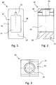
- the in 1 to 3 shown clamping body 10 has a clamping body pocket 12 which is formed from a solid profile and is produced by machining, in particular milling, broaching and drilling, for example from a rectangular profile wire.
- the clamp body pocket 12 has a receiving space 14, which in the form of a, as in Fig. 2 through hole is formed, through which an electrical conductor (not shown here) to be clamped and connected can be introduced.
- the receiving space 14 is delimited by a first side wall 16, a second side wall 18, a bottom side wall 20 and a ceiling side wall 22 of the sprag pocket 12.
- a threaded bore 24 is formed in the ceiling-side wall 22 for receiving a screw, not shown here, by means of which the conductor inserted into the receiving space 14 can be clamped and connected.
- Fig. 3 the terminal block is shown in a plan view of the ceiling-side wall 22 in which the threaded bore 24 is provided.
- the clamp body pocket 12 is made of an electrically conductive, lead-free aluminum-containing alloy, AlSilMgCuMn, which has a tensile strength between 380 N / mm 2 and 480 N / mm 2 and is particularly good due to its particularly good machinability Corrosion resistance, no or only very low relaxation properties, low weight and low manufacturing costs.
Landscapes
- Chemical & Material Sciences (AREA)
- Engineering & Computer Science (AREA)
- Materials Engineering (AREA)
- Mechanical Engineering (AREA)
- Metallurgy (AREA)
- Organic Chemistry (AREA)
- Clamps And Clips (AREA)
Priority Applications (1)
| Application Number | Priority Date | Filing Date | Title |
|---|---|---|---|
| PL11738617T PL2593573T3 (pl) | 2010-07-13 | 2011-07-08 | Korpus zaciskowy dla przewodu elektrycznego |
Applications Claiming Priority (2)
| Application Number | Priority Date | Filing Date | Title |
|---|---|---|---|
| DE102010027082A DE102010027082A1 (de) | 2010-07-13 | 2010-07-13 | Klemmkörper für einen elektrischen Leiter |
| PCT/EP2011/003422 WO2012007136A1 (de) | 2010-07-13 | 2011-07-08 | Klemmkörper für einen elektrischen leiter |
Publications (2)
| Publication Number | Publication Date |
|---|---|
| EP2593573A1 EP2593573A1 (de) | 2013-05-22 |
| EP2593573B1 true EP2593573B1 (de) | 2020-03-11 |
Family
ID=44486831
Family Applications (1)
| Application Number | Title | Priority Date | Filing Date |
|---|---|---|---|
| EP11738617.7A Active EP2593573B1 (de) | 2010-07-13 | 2011-07-08 | Klemmkörper für einen elektrischen leiter |
Country Status (7)
| Country | Link |
|---|---|
| US (1) | US8911270B2 (pl) |
| EP (1) | EP2593573B1 (pl) |
| CN (1) | CN103052730B (pl) |
| DE (1) | DE102010027082A1 (pl) |
| ES (1) | ES2784126T3 (pl) |
| PL (1) | PL2593573T3 (pl) |
| WO (1) | WO2012007136A1 (pl) |
Families Citing this family (3)
| Publication number | Priority date | Publication date | Assignee | Title |
|---|---|---|---|---|
| JP5934618B2 (ja) * | 2012-09-14 | 2016-06-15 | 矢崎総業株式会社 | 端子金具 |
| DE102014012489B4 (de) | 2014-08-27 | 2025-02-06 | Auto-Kabel Management Gmbh | Anschlussteil für Aluminiumleitungen |
| DE202018104958U1 (de) | 2018-08-30 | 2018-09-12 | Harting Electric Gmbh & Co. Kg | Steckverbinder mit Komponenten aus verbessertem Material |
Citations (2)
| Publication number | Priority date | Publication date | Assignee | Title |
|---|---|---|---|---|
| CH554603A (de) * | 1972-09-15 | 1974-09-30 | Pfisterer Elektrotech Karl | Klemme zum verbinden der enden von elektrischen leitern. |
| US6338658B1 (en) * | 2000-02-14 | 2002-01-15 | Ilsco Corporation | Slotted electrical connector |
Family Cites Families (9)
| Publication number | Priority date | Publication date | Assignee | Title |
|---|---|---|---|---|
| US2193202A (en) * | 1939-03-13 | 1940-03-12 | Cutler Hammer Inc | Wiring-terminal device |
| GB718602A (en) | 1951-08-27 | 1954-11-17 | Rohland Paul Gerhard | Improvements in rope clamps and methods for their application |
| US3516049A (en) * | 1968-06-12 | 1970-06-02 | Gen Electric | Multiple electrical terminal connector for panelboards and/or load centers |
| SU449967A1 (ru) | 1972-11-13 | 1974-11-15 | Предприятие П/Я А-6585 | Сплав на основе алюмини |
| FR2312839A1 (fr) | 1975-05-28 | 1976-12-24 | Pechiney Aluminium | Conducteurs electriques ameliores en alliages al-mg-si, en particulier pour cables aeriens de transport d'energie, et procede d'obtention |
| JPS6389640A (ja) * | 1986-10-01 | 1988-04-20 | Sky Alum Co Ltd | 電子電気機器導電部品材料 |
| WO1994012677A1 (de) * | 1992-11-20 | 1994-06-09 | 'techma' Gesellschaft Mit Beschränkter Haftung | Aluminiumlegierung |
| DE102005061732B4 (de) * | 2005-12-21 | 2015-01-08 | Phoenix Contact Gmbh & Co. Kg | Verfahren zur Bildung einer Struktur an einem Klemmkörper für eine Schraubklemme |
| FR2902442B1 (fr) * | 2006-06-16 | 2010-09-03 | Aleris Aluminum Koblenz Gmbh | Alliage de la serie aa6xxx, a grande tolerance aux dommages pour l'industrie aerospatiale |
-
2010
- 2010-07-13 DE DE102010027082A patent/DE102010027082A1/de not_active Ceased
-
2011
- 2011-07-08 EP EP11738617.7A patent/EP2593573B1/de active Active
- 2011-07-08 PL PL11738617T patent/PL2593573T3/pl unknown
- 2011-07-08 ES ES11738617T patent/ES2784126T3/es active Active
- 2011-07-08 WO PCT/EP2011/003422 patent/WO2012007136A1/de not_active Ceased
- 2011-07-08 CN CN201180037171.6A patent/CN103052730B/zh not_active Expired - Fee Related
- 2011-07-08 US US13/809,593 patent/US8911270B2/en not_active Expired - Fee Related
Patent Citations (2)
| Publication number | Priority date | Publication date | Assignee | Title |
|---|---|---|---|---|
| CH554603A (de) * | 1972-09-15 | 1974-09-30 | Pfisterer Elektrotech Karl | Klemme zum verbinden der enden von elektrischen leitern. |
| US6338658B1 (en) * | 2000-02-14 | 2002-01-15 | Ilsco Corporation | Slotted electrical connector |
Also Published As
| Publication number | Publication date |
|---|---|
| DE102010027082A1 (de) | 2012-01-19 |
| ES2784126T3 (es) | 2020-09-22 |
| CN103052730B (zh) | 2017-07-07 |
| EP2593573A1 (de) | 2013-05-22 |
| PL2593573T3 (pl) | 2020-07-13 |
| US20130115827A1 (en) | 2013-05-09 |
| WO2012007136A1 (de) | 2012-01-19 |
| US8911270B2 (en) | 2014-12-16 |
| CN103052730A (zh) | 2013-04-17 |
Similar Documents
| Publication | Publication Date | Title |
|---|---|---|
| EP2867547B1 (de) | Abreissschraube, zugehöriges system sowie vorrichtung zum schraubklemmen elektrischer leiter mit einer solchen abreissschraube | |
| DE112011102402B4 (de) | Draht mit Anschluss | |
| DE10358686B4 (de) | Crimpkontaktelement | |
| DE102014012489B4 (de) | Anschlussteil für Aluminiumleitungen | |
| EP3529389B1 (de) | Kupfer-zink-legierung | |
| DE102014014239B4 (de) | Elektrisches Verbindungselement | |
| DE102021213562A1 (de) | Elektrische Kontaktanordnung sowie vorgefertigte Baugruppe | |
| DE102014117410B4 (de) | Elektrisches Kontaktelement, Einpressstift, Buchse und Leadframe | |
| EP2593573B1 (de) | Klemmkörper für einen elektrischen leiter | |
| DE112012003197T5 (de) | Anschluss | |
| EP1756437B1 (de) | Bautteil mit einem drahtgewindeeinsatz aus magnesium- oder aluminiumlegierung | |
| EP3605739A1 (en) | Connection structure | |
| EP2758556B1 (de) | Klemmkörper für einen elektrischen leiter | |
| EP2596157B1 (de) | Einpresspin und verfahren zu seiner herstellung | |
| EP4094326B1 (de) | Verbindungsanordnung und verfahren zum verbinden einer verbindungsanordnung mit einem bauteil | |
| DE102011088211A1 (de) | Kontaktelement und Verfahren zu seiner Herstellung | |
| WO2016055480A1 (de) | Verfahren zur herstellung eines verbindungselements, verbindungselement sowie verwendung des verbindungselements | |
| WO2009062469A2 (de) | Elektrischer leiter und stanzgitter mit stegleitern aus einem solchen elektrischen leiter | |
| DE102016100081B4 (de) | Elektrische verbindung zwischen elektrisch leitenden bauteilen | |
| DE102017113269B4 (de) | Polklemme | |
| DE102011053828A1 (de) | Klemmkörper | |
| DE102016120087A1 (de) | Verbindungselement zum Befestigen eines Metallteils an einer Leiterplatte | |
| DE102012017609A1 (de) | Anschlussklemme | |
| DD208015A1 (de) | Elektrisch leitende verbindung | |
| DE202007006143U1 (de) | Sammelschiene für elektrische Verteiler |
Legal Events
| Date | Code | Title | Description |
|---|---|---|---|
| PUAI | Public reference made under article 153(3) epc to a published international application that has entered the european phase |
Free format text: ORIGINAL CODE: 0009012 |
|
| 17P | Request for examination filed |
Effective date: 20121220 |
|
| AK | Designated contracting states |
Kind code of ref document: A1 Designated state(s): AL AT BE BG CH CY CZ DE DK EE ES FI FR GB GR HR HU IE IS IT LI LT LU LV MC MK MT NL NO PL PT RO RS SE SI SK SM TR |
|
| DAX | Request for extension of the european patent (deleted) | ||
| STAA | Information on the status of an ep patent application or granted ep patent |
Free format text: STATUS: EXAMINATION IS IN PROGRESS |
|
| 17Q | First examination report despatched |
Effective date: 20170322 |
|
| GRAP | Despatch of communication of intention to grant a patent |
Free format text: ORIGINAL CODE: EPIDOSNIGR1 |
|
| STAA | Information on the status of an ep patent application or granted ep patent |
Free format text: STATUS: GRANT OF PATENT IS INTENDED |
|
| INTG | Intention to grant announced |
Effective date: 20191007 |
|
| GRAS | Grant fee paid |
Free format text: ORIGINAL CODE: EPIDOSNIGR3 |
|
| GRAA | (expected) grant |
Free format text: ORIGINAL CODE: 0009210 |
|
| STAA | Information on the status of an ep patent application or granted ep patent |
Free format text: STATUS: THE PATENT HAS BEEN GRANTED |
|
| AK | Designated contracting states |
Kind code of ref document: B1 Designated state(s): AL AT BE BG CH CY CZ DE DK EE ES FI FR GB GR HR HU IE IS IT LI LT LU LV MC MK MT NL NO PL PT RO RS SE SI SK SM TR |
|
| REG | Reference to a national code |
Ref country code: GB Ref legal event code: FG4D Free format text: NOT ENGLISH |
|
| REG | Reference to a national code |
Ref country code: CH Ref legal event code: EP |
|
| REG | Reference to a national code |
Ref country code: AT Ref legal event code: REF Ref document number: 1243212 Country of ref document: AT Kind code of ref document: T Effective date: 20200315 |
|
| REG | Reference to a national code |
Ref country code: DE Ref legal event code: R096 Ref document number: 502011016538 Country of ref document: DE |
|
| REG | Reference to a national code |
Ref country code: IE Ref legal event code: FG4D Free format text: LANGUAGE OF EP DOCUMENT: GERMAN |
|
| REG | Reference to a national code |
Ref country code: NL Ref legal event code: FP |
|
| PG25 | Lapsed in a contracting state [announced via postgrant information from national office to epo] |
Ref country code: RS Free format text: LAPSE BECAUSE OF FAILURE TO SUBMIT A TRANSLATION OF THE DESCRIPTION OR TO PAY THE FEE WITHIN THE PRESCRIBED TIME-LIMIT Effective date: 20200311 Ref country code: NO Free format text: LAPSE BECAUSE OF FAILURE TO SUBMIT A TRANSLATION OF THE DESCRIPTION OR TO PAY THE FEE WITHIN THE PRESCRIBED TIME-LIMIT Effective date: 20200611 Ref country code: FI Free format text: LAPSE BECAUSE OF FAILURE TO SUBMIT A TRANSLATION OF THE DESCRIPTION OR TO PAY THE FEE WITHIN THE PRESCRIBED TIME-LIMIT Effective date: 20200311 |
|
| PG25 | Lapsed in a contracting state [announced via postgrant information from national office to epo] |
Ref country code: BG Free format text: LAPSE BECAUSE OF FAILURE TO SUBMIT A TRANSLATION OF THE DESCRIPTION OR TO PAY THE FEE WITHIN THE PRESCRIBED TIME-LIMIT Effective date: 20200611 Ref country code: SE Free format text: LAPSE BECAUSE OF FAILURE TO SUBMIT A TRANSLATION OF THE DESCRIPTION OR TO PAY THE FEE WITHIN THE PRESCRIBED TIME-LIMIT Effective date: 20200311 Ref country code: HR Free format text: LAPSE BECAUSE OF FAILURE TO SUBMIT A TRANSLATION OF THE DESCRIPTION OR TO PAY THE FEE WITHIN THE PRESCRIBED TIME-LIMIT Effective date: 20200311 Ref country code: GR Free format text: LAPSE BECAUSE OF FAILURE TO SUBMIT A TRANSLATION OF THE DESCRIPTION OR TO PAY THE FEE WITHIN THE PRESCRIBED TIME-LIMIT Effective date: 20200612 Ref country code: LV Free format text: LAPSE BECAUSE OF FAILURE TO SUBMIT A TRANSLATION OF THE DESCRIPTION OR TO PAY THE FEE WITHIN THE PRESCRIBED TIME-LIMIT Effective date: 20200311 |
|
| REG | Reference to a national code |
Ref country code: LT Ref legal event code: MG4D |
|
| REG | Reference to a national code |
Ref country code: ES Ref legal event code: FG2A Ref document number: 2784126 Country of ref document: ES Kind code of ref document: T3 Effective date: 20200922 |
|
| PG25 | Lapsed in a contracting state [announced via postgrant information from national office to epo] |
Ref country code: EE Free format text: LAPSE BECAUSE OF FAILURE TO SUBMIT A TRANSLATION OF THE DESCRIPTION OR TO PAY THE FEE WITHIN THE PRESCRIBED TIME-LIMIT Effective date: 20200311 Ref country code: SM Free format text: LAPSE BECAUSE OF FAILURE TO SUBMIT A TRANSLATION OF THE DESCRIPTION OR TO PAY THE FEE WITHIN THE PRESCRIBED TIME-LIMIT Effective date: 20200311 Ref country code: SK Free format text: LAPSE BECAUSE OF FAILURE TO SUBMIT A TRANSLATION OF THE DESCRIPTION OR TO PAY THE FEE WITHIN THE PRESCRIBED TIME-LIMIT Effective date: 20200311 Ref country code: CZ Free format text: LAPSE BECAUSE OF FAILURE TO SUBMIT A TRANSLATION OF THE DESCRIPTION OR TO PAY THE FEE WITHIN THE PRESCRIBED TIME-LIMIT Effective date: 20200311 Ref country code: IS Free format text: LAPSE BECAUSE OF FAILURE TO SUBMIT A TRANSLATION OF THE DESCRIPTION OR TO PAY THE FEE WITHIN THE PRESCRIBED TIME-LIMIT Effective date: 20200711 Ref country code: RO Free format text: LAPSE BECAUSE OF FAILURE TO SUBMIT A TRANSLATION OF THE DESCRIPTION OR TO PAY THE FEE WITHIN THE PRESCRIBED TIME-LIMIT Effective date: 20200311 Ref country code: PT Free format text: LAPSE BECAUSE OF FAILURE TO SUBMIT A TRANSLATION OF THE DESCRIPTION OR TO PAY THE FEE WITHIN THE PRESCRIBED TIME-LIMIT Effective date: 20200805 Ref country code: LT Free format text: LAPSE BECAUSE OF FAILURE TO SUBMIT A TRANSLATION OF THE DESCRIPTION OR TO PAY THE FEE WITHIN THE PRESCRIBED TIME-LIMIT Effective date: 20200311 |
|
| PGFP | Annual fee paid to national office [announced via postgrant information from national office to epo] |
Ref country code: PL Payment date: 20200701 Year of fee payment: 10 |
|
| REG | Reference to a national code |
Ref country code: DE Ref legal event code: R097 Ref document number: 502011016538 Country of ref document: DE |
|
| PLBE | No opposition filed within time limit |
Free format text: ORIGINAL CODE: 0009261 |
|
| STAA | Information on the status of an ep patent application or granted ep patent |
Free format text: STATUS: NO OPPOSITION FILED WITHIN TIME LIMIT |
|
| PG25 | Lapsed in a contracting state [announced via postgrant information from national office to epo] |
Ref country code: DK Free format text: LAPSE BECAUSE OF FAILURE TO SUBMIT A TRANSLATION OF THE DESCRIPTION OR TO PAY THE FEE WITHIN THE PRESCRIBED TIME-LIMIT Effective date: 20200311 |
|
| 26N | No opposition filed |
Effective date: 20201214 |
|
| PG25 | Lapsed in a contracting state [announced via postgrant information from national office to epo] |
Ref country code: MC Free format text: LAPSE BECAUSE OF FAILURE TO SUBMIT A TRANSLATION OF THE DESCRIPTION OR TO PAY THE FEE WITHIN THE PRESCRIBED TIME-LIMIT Effective date: 20200311 Ref country code: SI Free format text: LAPSE BECAUSE OF FAILURE TO SUBMIT A TRANSLATION OF THE DESCRIPTION OR TO PAY THE FEE WITHIN THE PRESCRIBED TIME-LIMIT Effective date: 20200311 |
|
| REG | Reference to a national code |
Ref country code: CH Ref legal event code: PL |
|
| REG | Reference to a national code |
Ref country code: NL Ref legal event code: MM Effective date: 20200801 |
|
| GBPC | Gb: european patent ceased through non-payment of renewal fee |
Effective date: 20200708 |
|
| REG | Reference to a national code |
Ref country code: BE Ref legal event code: MM Effective date: 20200731 |
|
| PG25 | Lapsed in a contracting state [announced via postgrant information from national office to epo] |
Ref country code: NL Free format text: LAPSE BECAUSE OF NON-PAYMENT OF DUE FEES Effective date: 20200801 Ref country code: LU Free format text: LAPSE BECAUSE OF NON-PAYMENT OF DUE FEES Effective date: 20200708 Ref country code: GB Free format text: LAPSE BECAUSE OF NON-PAYMENT OF DUE FEES Effective date: 20200708 Ref country code: FR Free format text: LAPSE BECAUSE OF NON-PAYMENT OF DUE FEES Effective date: 20200731 Ref country code: LI Free format text: LAPSE BECAUSE OF NON-PAYMENT OF DUE FEES Effective date: 20200731 Ref country code: CH Free format text: LAPSE BECAUSE OF NON-PAYMENT OF DUE FEES Effective date: 20200731 |
|
| PG25 | Lapsed in a contracting state [announced via postgrant information from national office to epo] |
Ref country code: BE Free format text: LAPSE BECAUSE OF NON-PAYMENT OF DUE FEES Effective date: 20200731 |
|
| PG25 | Lapsed in a contracting state [announced via postgrant information from national office to epo] |
Ref country code: IE Free format text: LAPSE BECAUSE OF NON-PAYMENT OF DUE FEES Effective date: 20200708 |
|
| REG | Reference to a national code |
Ref country code: AT Ref legal event code: MM01 Ref document number: 1243212 Country of ref document: AT Kind code of ref document: T Effective date: 20200708 |
|
| PG25 | Lapsed in a contracting state [announced via postgrant information from national office to epo] |
Ref country code: AT Free format text: LAPSE BECAUSE OF NON-PAYMENT OF DUE FEES Effective date: 20200708 Ref country code: IT Free format text: LAPSE BECAUSE OF NON-PAYMENT OF DUE FEES Effective date: 20200708 |
|
| REG | Reference to a national code |
Ref country code: ES Ref legal event code: FD2A Effective date: 20211228 |
|
| PG25 | Lapsed in a contracting state [announced via postgrant information from national office to epo] |
Ref country code: ES Free format text: LAPSE BECAUSE OF NON-PAYMENT OF DUE FEES Effective date: 20200709 |
|
| PG25 | Lapsed in a contracting state [announced via postgrant information from national office to epo] |
Ref country code: TR Free format text: LAPSE BECAUSE OF FAILURE TO SUBMIT A TRANSLATION OF THE DESCRIPTION OR TO PAY THE FEE WITHIN THE PRESCRIBED TIME-LIMIT Effective date: 20200311 Ref country code: MT Free format text: LAPSE BECAUSE OF FAILURE TO SUBMIT A TRANSLATION OF THE DESCRIPTION OR TO PAY THE FEE WITHIN THE PRESCRIBED TIME-LIMIT Effective date: 20200311 Ref country code: CY Free format text: LAPSE BECAUSE OF FAILURE TO SUBMIT A TRANSLATION OF THE DESCRIPTION OR TO PAY THE FEE WITHIN THE PRESCRIBED TIME-LIMIT Effective date: 20200311 |
|
| PG25 | Lapsed in a contracting state [announced via postgrant information from national office to epo] |
Ref country code: MK Free format text: LAPSE BECAUSE OF FAILURE TO SUBMIT A TRANSLATION OF THE DESCRIPTION OR TO PAY THE FEE WITHIN THE PRESCRIBED TIME-LIMIT Effective date: 20200311 Ref country code: AL Free format text: LAPSE BECAUSE OF FAILURE TO SUBMIT A TRANSLATION OF THE DESCRIPTION OR TO PAY THE FEE WITHIN THE PRESCRIBED TIME-LIMIT Effective date: 20200311 |
|
| P01 | Opt-out of the competence of the unified patent court (upc) registered |
Effective date: 20230424 |
|
| PG25 | Lapsed in a contracting state [announced via postgrant information from national office to epo] |
Ref country code: PL Free format text: LAPSE BECAUSE OF NON-PAYMENT OF DUE FEES Effective date: 20210708 |
|
| PGFP | Annual fee paid to national office [announced via postgrant information from national office to epo] |
Ref country code: DE Payment date: 20230928 Year of fee payment: 13 |
|
| REG | Reference to a national code |
Ref country code: DE Ref legal event code: R119 Ref document number: 502011016538 Country of ref document: DE |
|
| PG25 | Lapsed in a contracting state [announced via postgrant information from national office to epo] |
Ref country code: DE Free format text: LAPSE BECAUSE OF NON-PAYMENT OF DUE FEES Effective date: 20250201 |