EP2592057A1 - Glass substrate end surface evaluation method, glass substrate end surface processing method, and glass substrate - Google Patents
Glass substrate end surface evaluation method, glass substrate end surface processing method, and glass substrate Download PDFInfo
- Publication number
- EP2592057A1 EP2592057A1 EP11803355.4A EP11803355A EP2592057A1 EP 2592057 A1 EP2592057 A1 EP 2592057A1 EP 11803355 A EP11803355 A EP 11803355A EP 2592057 A1 EP2592057 A1 EP 2592057A1
- Authority
- EP
- European Patent Office
- Prior art keywords
- glass substrate
- end surface
- image
- area
- processing
- Prior art date
- Legal status (The legal status is an assumption and is not a legal conclusion. Google has not performed a legal analysis and makes no representation as to the accuracy of the status listed.)
- Withdrawn
Links
Images








Classifications
-
- G—PHYSICS
- G01—MEASURING; TESTING
- G01N—INVESTIGATING OR ANALYSING MATERIALS BY DETERMINING THEIR CHEMICAL OR PHYSICAL PROPERTIES
- G01N21/00—Investigating or analysing materials by the use of optical means, i.e. using sub-millimetre waves, infrared, visible or ultraviolet light
- G01N21/84—Systems specially adapted for particular applications
- G01N21/88—Investigating the presence of flaws or contamination
- G01N21/89—Investigating the presence of flaws or contamination in moving material, e.g. running paper or textiles
- G01N21/892—Investigating the presence of flaws or contamination in moving material, e.g. running paper or textiles characterised by the flaw, defect or object feature examined
- G01N21/896—Optical defects in or on transparent materials, e.g. distortion, surface flaws in conveyed flat sheet or rod
-
- B—PERFORMING OPERATIONS; TRANSPORTING
- B24—GRINDING; POLISHING
- B24B—MACHINES, DEVICES, OR PROCESSES FOR GRINDING OR POLISHING; DRESSING OR CONDITIONING OF ABRADING SURFACES; FEEDING OF GRINDING, POLISHING, OR LAPPING AGENTS
- B24B49/00—Measuring or gauging equipment for controlling the feed movement of the grinding tool or work; Arrangements of indicating or measuring equipment, e.g. for indicating the start of the grinding operation
- B24B49/10—Measuring or gauging equipment for controlling the feed movement of the grinding tool or work; Arrangements of indicating or measuring equipment, e.g. for indicating the start of the grinding operation involving electrical means
-
- B—PERFORMING OPERATIONS; TRANSPORTING
- B24—GRINDING; POLISHING
- B24B—MACHINES, DEVICES, OR PROCESSES FOR GRINDING OR POLISHING; DRESSING OR CONDITIONING OF ABRADING SURFACES; FEEDING OF GRINDING, POLISHING, OR LAPPING AGENTS
- B24B49/00—Measuring or gauging equipment for controlling the feed movement of the grinding tool or work; Arrangements of indicating or measuring equipment, e.g. for indicating the start of the grinding operation
- B24B49/12—Measuring or gauging equipment for controlling the feed movement of the grinding tool or work; Arrangements of indicating or measuring equipment, e.g. for indicating the start of the grinding operation involving optical means
-
- B—PERFORMING OPERATIONS; TRANSPORTING
- B24—GRINDING; POLISHING
- B24B—MACHINES, DEVICES, OR PROCESSES FOR GRINDING OR POLISHING; DRESSING OR CONDITIONING OF ABRADING SURFACES; FEEDING OF GRINDING, POLISHING, OR LAPPING AGENTS
- B24B9/00—Machines or devices designed for grinding edges or bevels on work or for removing burrs; Accessories therefor
- B24B9/02—Machines or devices designed for grinding edges or bevels on work or for removing burrs; Accessories therefor characterised by a special design with respect to properties of materials specific to articles to be ground
- B24B9/06—Machines or devices designed for grinding edges or bevels on work or for removing burrs; Accessories therefor characterised by a special design with respect to properties of materials specific to articles to be ground of non-metallic inorganic material, e.g. stone, ceramics, porcelain
- B24B9/08—Machines or devices designed for grinding edges or bevels on work or for removing burrs; Accessories therefor characterised by a special design with respect to properties of materials specific to articles to be ground of non-metallic inorganic material, e.g. stone, ceramics, porcelain of glass
- B24B9/10—Machines or devices designed for grinding edges or bevels on work or for removing burrs; Accessories therefor characterised by a special design with respect to properties of materials specific to articles to be ground of non-metallic inorganic material, e.g. stone, ceramics, porcelain of glass of plate glass
-
- C—CHEMISTRY; METALLURGY
- C03—GLASS; MINERAL OR SLAG WOOL
- C03C—CHEMICAL COMPOSITION OF GLASSES, GLAZES OR VITREOUS ENAMELS; SURFACE TREATMENT OF GLASS; SURFACE TREATMENT OF FIBRES OR FILAMENTS MADE FROM GLASS, MINERALS OR SLAGS; JOINING GLASS TO GLASS OR OTHER MATERIALS
- C03C19/00—Surface treatment of glass, not in the form of fibres or filaments, by mechanical means
-
- G—PHYSICS
- G01—MEASURING; TESTING
- G01N—INVESTIGATING OR ANALYSING MATERIALS BY DETERMINING THEIR CHEMICAL OR PHYSICAL PROPERTIES
- G01N21/00—Investigating or analysing materials by the use of optical means, i.e. using sub-millimetre waves, infrared, visible or ultraviolet light
- G01N21/84—Systems specially adapted for particular applications
- G01N21/88—Investigating the presence of flaws or contamination
- G01N21/95—Investigating the presence of flaws or contamination characterised by the material or shape of the object to be examined
-
- G—PHYSICS
- G01—MEASURING; TESTING
- G01N—INVESTIGATING OR ANALYSING MATERIALS BY DETERMINING THEIR CHEMICAL OR PHYSICAL PROPERTIES
- G01N21/00—Investigating or analysing materials by the use of optical means, i.e. using sub-millimetre waves, infrared, visible or ultraviolet light
- G01N21/84—Systems specially adapted for particular applications
- G01N21/88—Investigating the presence of flaws or contamination
- G01N21/95—Investigating the presence of flaws or contamination characterised by the material or shape of the object to be examined
- G01N21/9501—Semiconductor wafers
- G01N21/9503—Wafer edge inspection
-
- G—PHYSICS
- G06—COMPUTING OR CALCULATING; COUNTING
- G06T—IMAGE DATA PROCESSING OR GENERATION, IN GENERAL
- G06T7/00—Image analysis
- G06T7/40—Analysis of texture
-
- G—PHYSICS
- G01—MEASURING; TESTING
- G01N—INVESTIGATING OR ANALYSING MATERIALS BY DETERMINING THEIR CHEMICAL OR PHYSICAL PROPERTIES
- G01N21/00—Investigating or analysing materials by the use of optical means, i.e. using sub-millimetre waves, infrared, visible or ultraviolet light
- G01N21/84—Systems specially adapted for particular applications
- G01N21/88—Investigating the presence of flaws or contamination
- G01N21/95—Investigating the presence of flaws or contamination characterised by the material or shape of the object to be examined
- G01N2021/9511—Optical elements other than lenses, e.g. mirrors
-
- G—PHYSICS
- G01—MEASURING; TESTING
- G01N—INVESTIGATING OR ANALYSING MATERIALS BY DETERMINING THEIR CHEMICAL OR PHYSICAL PROPERTIES
- G01N21/00—Investigating or analysing materials by the use of optical means, i.e. using sub-millimetre waves, infrared, visible or ultraviolet light
- G01N21/84—Systems specially adapted for particular applications
- G01N21/88—Investigating the presence of flaws or contamination
- G01N21/95—Investigating the presence of flaws or contamination characterised by the material or shape of the object to be examined
- G01N2021/9513—Liquid crystal panels
-
- Y—GENERAL TAGGING OF NEW TECHNOLOGICAL DEVELOPMENTS; GENERAL TAGGING OF CROSS-SECTIONAL TECHNOLOGIES SPANNING OVER SEVERAL SECTIONS OF THE IPC; TECHNICAL SUBJECTS COVERED BY FORMER USPC CROSS-REFERENCE ART COLLECTIONS [XRACs] AND DIGESTS
- Y10—TECHNICAL SUBJECTS COVERED BY FORMER USPC
- Y10T—TECHNICAL SUBJECTS COVERED BY FORMER US CLASSIFICATION
- Y10T428/00—Stock material or miscellaneous articles
- Y10T428/24—Structurally defined web or sheet [e.g., overall dimension, etc.]
- Y10T428/24777—Edge feature
Definitions
- the present invention relates to a method of evaluating an end surface of a glass substrate that is used for an FPD (Flat Panel Display), a method of processing the end surface of the glass substrate, and a glass substrate.
- FPD Full Panel Display
- An end surface of the FPD glass substrate which is used in a liquid crystal display, a plasma display, or the like, is chamfered with a grinding member in a manufacturing process.
- end surface shapes of the chamfered glass substrate are largely classified into an end surface shape having a single curved surface R 1 as shown in Fig. 24A and an end surface shape having a flat portion E and two curved surfaces R 2 and R 2 having the same curvature as shown in Fig. 24B .
- a cross-section in which a chamfered end surface is enlarged is shown, and a symbol G represents the glass substrate.
- a Ra value of the end surface roughness of the glass substrate is defined to 0.25 ⁇ m or less, and in the patent reference 2, the Ra value is defined to 0.1 ⁇ m or less so as to suppress the adhesion of the dust to the end surface.
- Measurement of the end surface roughness of the glass substrate is performed using a probe-type surface roughness meter provided with a probe as disclosed in the patent reference 2.
- the patent reference 3 discloses an invention related to the chamfer shape of an outer peripheral end surface of a substrate for a hard disk.
- An object of the patent reference 3 is to prevent a substrate main body of the substrate for the hard disk, which is manufactured using a brittle material, such as a carbon substrate and a glass substrate, from becoming a defective article during handling thereof.
- the object is to prevent defects such as flaw and cracking of the outer peripheral end surface from occurring when the outer peripheral end surface of the substrate main body comes into contact with a cassette for conveyance.
- the patent reference 3 discloses a substrate for a magnetic recording medium in which a chamfered portion on an outer peripheral end surface of a substrate main body having an outer diameter of 65 mm is made to have a round shape, this round chamfered portion makes up a side portion in a round shape having only one radius, and a round radius R is set to t/2 to 2t (here, t represents a plate thickness of the substrate main body).
- the patent reference 1 also discloses a substrate for a magnetic recording medium in which a chamfered portion has a roundness that is different at upper and lower sides of the substrate, and radii R 1 and R 2 are set to be less than t/2.
- the tip of the probe may pass over a minute recess, which is present in the end surface of the glass substrate, without entering the recess. Therefore, there is a problem in that it is difficult to accurately evaluate the properties and state of the end surface of the glass substrate. That is, in the method of evaluating the properties and state of the end surface of the glass substrate by the probe-type surface roughness meter, the reliability thereof depends greatly on the size of the recess, and thus the reliability is not superior.
- the burning defect does not easily occur during chamfering process of a small-sized hard disk substrate as shown in the patent reference 3, but occurs at an FPD glass substrate having a size of 400 mm ⁇ 300 mm or more. That is, as the travel distance of a grinding member with respect to the end surface of the glass substrate becomes longer, the frequency of occurrence of the burning defect tends to increase. Particularly, in a glass substrate having a size of 1,200 mm ⁇ 1, 100 mm or more, the frequency of occurrence of the burning defect problem becomes higher.
- the present invention has been made in consideration of the above-described circumstances, and an object thereof is to provide a method of evaluating an end surface of a glass substrate, which is capable of accurately evaluating the properties and state of the end surface of the glass substrate, a method of processing the end surface of the glass substrate on the basis of this evaluation method, and a glass substrate in which dust adhesion to the end surface of the glass substrate may be reduced on the basis of the processing method, and more particularly, a glass substrate in which defects such as burning defect, chipping, and cracking may be prevented from occurring on a chamfered surface on the basis of the processing method.
- a method of evaluating an end surface of a glass substrate includes: imaging a predetermined area of the end surface of the glass substrate with an imaging unit; processing the imaged image with white and black binarization to identify a recess that is present in the end surface and a flat portion that becomes a mirror surface of the end surface as a white image and a black image, respectively; and evaluating properties and a state of the end surface of the glass substrate on the basis of a ratio of an area of the white image with respect to an area of the black image.
- the evaluation method of the invention provides an evaluation method using an imaging unit such as a laser microscope.
- the image of the end surface which is imaged by the imaging unit, is processed with the white and black binarization to identify the recess that is present in the end surface and the flat portion that becomes the mirror surface of the end surface as the white image and the black image, respectively.
- the properties and state of the end surface of the glass substrate are evaluated on the basis of the ratio of the area of the white image with respect to the area of the black image.
- the properties and state of the end surface of the glass substrate may be evaluated in a relatively accurate manner.
- a threshold value of the ratio of the area of the white image with respect to the area of the black image be set to 10%.
- the present inventors made a thorough investigation on the ratio to suppress the adhesion of dust to the end surface. As a result thereof, they found that when the ratio exceeds 10%, dust easily adheres, and when the ratio is 10% or less, the dust does not easily adhere. Therefore, the threshold value of the ratio is appropriately set to 10% whenever the end surface of the glass substrate is evaluated.
- a method of processing an end surface of a glass substrate includes: grinding the end surface of the glass substrate with a grinding member; imaging the ground end surface with an imaging unit; processing the imaged image with white and black binarization to identify a recess that is present in the end surface and a flat portion that becomes a mirror surface of the end surface as a white image and a black image, respectively; and controlling a grinding volume of the end surface with the grinding member so that a ratio of an area of the white image with respect to an area of the black image becomes a predetermined threshold value or less.
- the grinding volume of the end surface with the grinding member is controlled on the basis of the ratio. That is, in a case where the ratio is larger than the threshold value, it is determined that the grinding volume (a run-in amount of the grinding member with respect to the end surface of the glass substrate) with the grinding member is small and a lot of recesses are present, and an optimal control is performed so that a finish quality becomes optimal. According to this, the quality of the end surface of the glass substrate is stabilized.
- control be performed so that the threshold value of the ratio of the area of the white image with respect to the area of the black image becomes 10% or less.
- a glass substrate in which dust does not easily adhere to the end surface of the glass substrate may be stably manufactured.
- a glass substrate that is processed with the method of processing an end surface of a glass substrate according to the invention.
- the glass substrate of the invention since dust does not easily adhere to the end surface of the glass substrate, a glass substrate with a superior quality may be provided.
- a glass substrate that is processed with the method of processing an end surface of a glass substrate according to the invention, wherein a size is 400 mm ⁇ 300 mm or more, a plate thickness (t) is 0.05 mm to 2.8 mm, and a trapezoidal shape, which is created by drawing three tangential lines on the end surface having a chamfered portion, satisfies the following dimensions.
- ⁇ represents an angle of aperture (an angle made by a tangential line of a chamfered curved surface of the end surface of the glass substrate at an intersection point between a plate surface of the glass substrate and the chamfered curved surface of the end surface of the glass substrate, and the plate surface of the glass substrate, and a range thereof is 50° ⁇ 2 ⁇ 80°)
- W represents an end surface width (a length from the intersection point between the plate surface of the glass substrate and the chamfered curved surface of the end surface of the glass substrate to a tangential line drawn on the tip of the end surface of the glass substrate in a direction parallel with the plate surface of the glass substrate)
- the end surface of the glass substrate and the chamfered surface are the same as each other, the length of a line segment connecting two intersection points between tangential lines A and B that are drawn on the chamfered curved surface of the glass substrate and a tangential line C that is drawn on the tip of the end surface of the glass substrate is set to the length (f).
- a glass substrate wherein in a case where a predetermined area of an end surface is imaged with an imaging unit, and the imaged image is processed with white and black binarization to identify a recess that is present in the end surface and a flat portion that becomes a mirror surface of the end surface as a white image and a black image, respectively, a ratio of an area of the white image with respect to an area of the black image is 10% or less.
- the predetermined area be an arbitrary area having dimensions of width: 100 ⁇ m ⁇ height: 50 ⁇ m within a region that has dimensions of depth: 10 mm ⁇ width: 20 mm and includes a central portion of an end surface processing region of the glass substrate in a traveling direction of a grindstone.
- the glass substrate according to the invention wherein a size is 400 mm ⁇ 300 mm or more, a plate thickness (t) is 0.05 mm to 2.8 mm, and a trapezoidal shape, which is created by drawing three tangential lines on the end surface having a chamfered portion, satisfies the following dimensions.
- ⁇ represents an angle of aperture (an angle made by a tangential line of a chamfered curved surface of the end surface of the glass substrate at an intersection point between a plate surface of the glass substrate and the chamfered curved surface of the end surface of the glass substrate, and the plate surface of the glass substrate, and a range thereof is 50° ⁇ 2 ⁇ 80°)
- W represents an end surface width (a length from the intersection point between the plate surface of the glass substrate and the chamfered curved surface of the end surface of the glass substrate to a tangential line drawn on a tip of the end surface of the glass substrate in a direction parallel with the plate surface of the glass substrate)
- the properties and state of the end surface of the glass substrate may be accurately evaluated.
- a glass substrate in which a quality of the end surface is stabilized may be manufactured.
- dust does not easily adhere to the end surface and defects such as burning defect, chipping, and cracking may be prevented from occurring on a chamfered surface.
- Fig. 1 shows a diagram illustrating a method of evaluating an end surface of a glass substrate related to the embodiment and a method of processing the end surface of the glass substrate related to the embodiment.
- a process of processing (chamfering) the end surface of the glass substrate G includes a processing process by a processing unit 12 provided with a chamfering grindstone (a grinding member) 10, and an inspection process by an inspection unit 16 provided with a laser microscope (VK-9500 manufactured by KYENCE CORPORATION) 14 that is an imaging unit.
- a processing unit 12 provided with a chamfering grindstone (a grinding member) 10
- an inspection process by an inspection unit 16 provided with a laser microscope (VK-9500 manufactured by KYENCE CORPORATION) 14 that is an imaging unit.
- the end surface Z of the glass substrate G is pressed with a recess 10A of the chamfering grindstone 10 that rotates. Therefore, the end surface Z is chamfered.
- a rough grinding process in which the end surface Z is rough ground, is provided in a previous stage of this processing process. Therefore, in the processing unit 12, the end surface Z is finish-ground into a mirror surface with the chamfering grindstone 10 that is a finish grindstone.
- the chamfering grindstone 10 is an elastic resin bond grindstone in which diamond or ceramic is used as an abrasive grain, and the abrasive grain and the bond contribute to the mirror surface finish processing of the end surface Z.
- a grit number Nos. 220 to 1,000 are preferable, and Nos. 220 to 600 are more preferable.
- the peripheral speed of the chamfering grindstone 10 is 470 to 3, 000 m/min, the grinding load during processing is managed as an electric current value or an electric power value, and the peripheral speed is controlled so that the grinding load becomes constant.
- a coolant liquid is supplied between the chamfering grindstone 10 and the end surface Z of the glass substrate G to prevent the end surface Z from being burned.
- the glass substrate G of which end surface Z is finish-ground with the processing unit 12 is moved for an inspection process, and a predetermined area of the end surface Z is imaged by a laser microscope 14 in the inspection unit 16.
- the area of the end surface Z that is to be imaged by the laser microscope 14 may be, for example, an area of a processing initiation portion of the end surface Z of the glass substrate, an area of a central portion of a region to be processed, or an area of a processing termination portion. Specifically, the following area may be selected.
- a sample which has dimensions of depth: 10 mm ⁇ width: 20 mm and which includes an end surface located at a position of 100 mm from a grindstone contact initiation position in the traveling direction of the grindstone, is cut from the glass substrate, and then an arbitrary area having dimensions of width: 100 ⁇ m ⁇ height: 50 ⁇ m may be selected from an end surface of the sample.
- an area having dimensions of width: 100 ⁇ m ⁇ height: 50 ⁇ m at the central portion of the end surface of the cut sample may be selected.
- a sample which has dimensions of depth: 10 mm ⁇ width: 20 mm and which includes the central portion of the end surface processing region of the glass substrate in the traveling direction of the grindstone, is cut from the glass substrate, and then an arbitrary area having dimensions of width: 100 ⁇ m ⁇ height: 50 ⁇ m may be selected from an end surface of the sample.
- an area having dimensions of width: 100 ⁇ m ⁇ height: 50 ⁇ m at the central portion of the end surface of the cut sample may be selected.
- a sample which has dimensions of depth: 10 mm ⁇ width: 20 mm and which includes an end surface located at a position of 100 mm from a grindstone contact termination position in a direction reverse to the traveling direction of the grindstone, is cut from the glass substrate, and then an arbitrary area having dimensions of width: 100 ⁇ m ⁇ height: 50 ⁇ m may be selected from an end surface of the sample.
- an area having dimensions of width: 100 ⁇ m ⁇ height: 50 ⁇ m at the central portion of the end surface of the cut sample may be selected.
- the laser microscope 14 is a digital microscope that uses laser light as a light source.
- Laser microscope 14 can detect an accurate focal position of the end surface Z of the glass substrate G, and thus in scanning in the height direction, an image with good contrast may be observed in a focused state.
- the laser microscope 14 may also measure surface roughness and surface shape and output of digital data of an enlarged image, in addition brightness information of the end surface Z of the glass substrate G, width of irregularity of the end surface Z of the glass substrate G, height of the irregularity of the end surface Z of the glass substrate G, or the like. That is, the irregularity state of the surface may be shown.
- High-resolution image data of the end surface Z that is imaged by the laser microscope 14 is output to an image processing unit 18.
- the image data is subjected to white and black binarization processing, a recess present in the end surface Z and a flat portion that becomes a mirror surface of the end surface Z are identified as a white image and a black image, respectively, and image data expressing the white image and the black image is output to a calculation unit 20.
- the white and black binarization processing is performed with the following method.
- An image obtained by imaging the end surface of the roughly ground glass substrate G with the laser microscope 14 is prepared. In this case, brightness becomes approximately constant.
- an image of the end surface is expressed with 255 gray scales.
- the rough grinding is performed with a metal bond grindstone of a grit number of Nos. 450 to 600.
- the peripheral speed of the metal bond grindstone is set to 470 to 3,000 m/minute, and the grinding load during processing is managed as a current value or a power value, and the peripheral speed is controlled so that the grinding load becomes constant.
- a coolant liquid is supplied between the metal bond grindstone and the end surface Z of the glass substrate G, and thus there is an effect of preventing the end surface Z from being burned.
- a difference in a gray scale between adjacent pixels of the obtained image is calculated, a frequency distribution of the difference value is obtained, and a standard deviation ⁇ thereof is calculated.
- This standard deviation ⁇ is set to a reference threshold value of the white and black binarization processing. That is, an image of the threshold value (standard deviation ⁇ ) or more is set to a white image, and an image of less than the threshold value (standard deviation ⁇ ) is set to a black image.
- the same processing is also performed with respect to the end surface that is subjected to the finish processing after the rough grinding, and the binarization processing is performed using the threshold value (standard deviation ⁇ ) obtained in the rough processing, and an area ratio between a white area and a black area is compared. According to this, detailed checking whether or not the finishing is satisfactory may be realized.
- calculation unit 20 the ratio of an area that is occupied by the white image with respect to an area that is occupied by the black image is calculated, and the ratio is displayed on a monitor 22. An operator checks this ratio, and on the basis of this ratio, the operator evaluates the properties and state of the end surface Z of the glass substrate G. In addition, the image of the end surface Z that is imaged by the laser microscope 14 and the image of the end surface Z that is subjected to the white and black binarization processing are also displayed on the monitor 22.
- the image of the end surface Z that is imaged by the laser microscope 14 is subjected to the white and black binarization processing, the recess that is present in the end surface and the flat portion that becomes the mirror surface of the end surface are identified as the white image and the black image, respectively, and the properties and state of the end surface of the glass substrate is evaluated on the basis of the ratio of the area of the white image with respect to the area of the black image.
- the properties and state of the end surface Z of the glass substrate G may be evaluated in a relatively accurate manner.
- a grindstone moving unit 24 is optimally controlled, so as to increase a grinding volume of the end surface Z with the chamfering grindstone 10.
- the present inventors made a thorough investigation on the ratio to suppress the adhesion of dust to the end surface Z. As a result thereof, they found that when the ratio exceeds 10%, the dust easily adheres, and when the ratio is 10% or less, the dust does not easily adhere. Therefore, the threshold value of the ratio is set to 10% whenever the end surface Z of the glass substrate G is evaluated.
- the grinding volume of the end surface Z with the chamfering grindstone 10 is optimally controlled on the basis of the ratio calculated by the calculation unit 20 as described above. That is, in a case where the calculated ratio is larger than 10% that is the threshold value, judging that the grinding volume with the chamfering grindstone 10 is small and a lot of recesses are present in the end surface Z, and thus the grindstone moving unit 24 is controlled so that a finish quality becomes optimal.
- the above-described ratio is controlled with moving the chamfering grindstone 10 with respect to the end surface Z in a direction of an arrow A in Fig. 1 so as to increase the grinding volume.
- the quality of the end surface Z of the glass substrate G is stabilized.
- dust does not easily adhere to the processed end surface Z of the glass substrate G, and thus the glass substrate G has a good quality.
- the glass substrate G in which the above-described ratio exceeds 10% is returned to the processing unit 12 from the inspection unit 16, and is processed again with the chamfering grindstone 10.
- the end surface Z of the glass substrate G having dimensions of 1,000 mm ⁇ 1,000 mm was roughly ground with a metal bond grindstone of a grit number of Nos. 450 to 600 while controlling a peripheral speed of 470 to 3, 000 m/minute so that the grinding load becomes constant. Subsequently, the end surface Z was finish-ground into a mirror surface with an elastic resin bond grindstone of a grit number of No. 600 as a finish grindstone while controlling the peripheral speed within a range of 470 to 3,000 m/minute so that the grinding load becomes constant.
- the photographic image shown in Fig. 2 represents the glass substrate G after process with the chamfering grindstone 10, and is a photographic image obtained by imaging the area of the processing central portion of the end surface Z of the glass substrate G with the laser microscope 14.
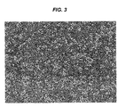
- Fig. 3 shows a photographic image in which the recess present in the end surface Z and the flat portion that becomes a mirror surface of the end surface are expressed in a color-coded manner as a white image and a black image, respectively, by processing the image data in Fig. 2 with white and black binarization, and the ratio thereof was calculated as 9.05% by the calculation unit 20.
- the ratio is 10% or less, it can be said that the mirror surface finish processing with the chamfering grindstone 10 was satisfactory, and thus dust does not easily adhere to the end surface Z.
- the roughness of the end surface Z was measured by a probe-type surface roughness shape measuring machine (product name: SURFCOM, manufactured by TOKYO SEIMITSU CO., LTD.; a cut off value: 0.25 mm; and measurement length: 10 mm), and as a result thereof, Ra was 0.11 ⁇ m.
- the end surface Z of the glass substrate G having dimensions of 1,000 mm ⁇ 1,000 mm was roughly ground with a metal bond grindstone of a grit number of Nos. 450 to 600 while controlling a peripheral speed of 470 to 3,000 m/minute so that the grinding load becomes constant. Subsequently, the end surface Z was finish-ground into a mirror surface with an elastic resin bond grindstone of a grit number of No. 220 as a finish grindstone while controlling the peripheral speed within a range of 470 to 3,000 m/minute so that the grinding load becomes constant.
- Fig. 4 represents the glass substrate G after process with the chamfering grindstone 10
- the photographic image is a photographic image that may be obtained by imaging the area of the processing central portion of the end surface Z of the glass substrate G with the laser microscope 14.
- Fig. 5 shows a photographic image in which the recess present in the end surface Z and the flat portion that becomes a mirror surface of the end surface are expressed in a color-coded manner as a white image and a black image, respectively, by processing the image data in Fig. 4 with white and black binarization, and the ratio thereof was calculated as 8.13% by the calculation unit 20. That is, in the end surface Z shown in Figs.
- the ratio is 10% or less, it can be said that the mirror surface finish processing with the chamfering grindstone 10 was satisfactory, and thus dust does not easily adhere to the end surface Z.
- the roughness of the end surface Z was measured by a probe-type surface roughness shape measuring machine (product name: SURFCOM, manufactured by TOKYO SEIMITSU CO., LTD.; a cut off value: 0.25 mm; and measurement length: 10 mm), and as a result thereof, Ra was 0.22 ⁇ m.
- the end surface Z of the glass substrate G having dimensions of 1,000 mm ⁇ 1,000 mm was roughly ground with a metal bond grindstone of a grit number of Nos. 450 to 600 while controlling a peripheral speed of 470 to 3, 000 m/minute so that the grinding load becomes constant. Subsequently, the end surface Z was finish-ground into a mirror surface with an elastic resin bond grindstone of a grit number of No. 320 as a finish grindstone while controlling the peripheral speed within a range of 470 to 3,000 m/minute so that the grinding load becomes constant.
- Fig. 6 represents the glass substrate G after process with the chamfering grindstone 10
- the photographic image is a photographic image that may be obtained by imaging the area of the processing central portion of the end surface Z of the glass substrate G with the laser microscope 14.
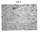
- Fig. 7 shows a photographic image in which the recess present in the end surface Z and the flat portion that becomes a mirror surface of the end surface are expressed in a color-coded manner as a white image and a black image, respectively, by processing the image data in Fig. 6 with white and black binarization, and the ratio thereof was calculated as 9.82% by the calculation unit 20. That is, in the end surface Z shown in Figs.
- the ratio is 10% or less, it can be said that the mirror surface finish processing with the chamfering grindstone 10 was satisfactory, and thus dust does not easily adhere to the end surface Z.
- the roughness of the end surface Z was measured by a probe-type surface roughness shape measuring machine (product name: SURFCOM, manufactured by TOKYO SEIMITSU CO., LTD.; a cut off value: 0.25 mm; and measurement length: 10 mm), and as a result thereof, Ra was 0.23 ⁇ m.
- the end surface Z of the glass substrate G having dimensions of 1,000 mm ⁇ 1,000 mm was roughly ground with a metal bond grindstone of a grit number of Nos. 450 to 600 while controlling a peripheral speed of 470 to 3, 000 m/minute so that the grinding load becomes constant.
- a photographic image shown in Fig. 8 represents the glass substrate G after an end surface rough grinding process and before processing with the chamfering finish grindstone 10, and the photographic image is a photographic image that may be obtained by imaging the area of the processing central portion of the roughly ground end surface Z of the glass substrate G with the laser microscope 14.
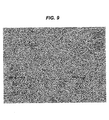
- Fig. 9 shows a photographic image in which the recess present in the end surface Z and the mirror surface on the end surface are expressed in a color-coded manner as a white image and a black image, respectively, by processing the image data in Fig. 8 with white and black binarization, and the ratio thereof was calculated as 22.67% by the calculation unit 20.
- Figs. 8 and 9 show the properties and state of the end surface Z of the glass substrate G before the processing with the chamfering grindstone 10.
- the roughness of the end surface Z was measured by a probe-type surface roughness shape measuring machine (product name: SURFCOM, manufactured by TOKYO SEIMITSU CO. , LTD. ; a cut off value: 0.25 mm; and measurement length: 10 mm), and as a result thereof, Ra was 0.45 ⁇ m.
- the end surface Z of the glass substrate G having dimensions of 1,000 mm ⁇ 1,000 mm was roughly ground with a metal bond grindstone of a grit number of Nos. 450 to 600 while controlling a peripheral speed of 470 to 3, 000 m/minute so that the grinding load becomes constant. Subsequently, the end surface Z was finish-ground into a mirror surface with resin bond grindstone of a grit number of Nos. 220 to 800 as a finish grindstone while controlling the peripheral speed within a range of 470 to 3, 000 m/minute so that the grinding load becomes constant.
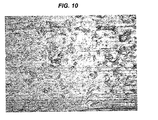
- the photographic image shown in Fig. 10 represents the glass substrate G after process with the chamfering grindstone 10, and the photographic image is a photographic image that may be obtained by imaging the area of the processing central portion of the end surface Z of the glass substrate G with the laser microscope 14.
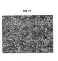
- Fig. 11 shows a photographic image in which the recess present in the end surface Z and the mirror surface on the end surface are expressed in a color-coded manner as a white image and a black image, respectively, by processing the image data in Fig. 10 with white and black binarization, and the ratio thereof was calculated as 13.10% by the calculation unit 20.
- the ratio exceeds 10%, and dust easily adheres to the end surface Z, it is necessary to again perform the mirror surface finish processing with the chamfering grindstone 10.
- the roughness of the end surface Z was measured by a probe-type surface roughness shape measuring machine (product name: SURFCOM, manufactured by TOKYO SEIMITSU CO., LTD. ; a cut off value: 0.25 mm; and measurement length: 10 mm), and as a result thereof, Ra was 0.32 ⁇ m.
- the photographic image shown in Fig. 12 represents the glass substrate G after process with the chamfering grindstone 10, and the photographic image is a photographic image that may be obtained by imaging the area of the processing central portion of the end surface Z of the glass substrate G with the laser microscope 14.
- Fig. 13 shows a photographic image in which the recess present in the end surface Z and the mirror surface on the end surface are expressed in a color-coded manner as a white image and a black image, respectively, by processing the image data in Fig. 12 with white and black binarization, and the ratio thereof was calculated as 16.73% by the calculation unit 20. That is, since in the end surface Z shown in Figs.
- the ratio exceeds 10%, and dust easily adheres to the end surface Z, it is necessary to again perform the mirror surface finish processing with the chamfering grindstone 10.
- the roughness of the end surface Z was measured by a probe-type surface roughness shape measuring machine (product name: SURFCOM, manufactured by TOKYO SEIMITSU CO., LTD. ; a cut off value: 0.25 mm; and measurement length: 10 mm), and as a result thereof, Ra was 0.14 ⁇ m.
- the ratio in Examples 2 and 3 is smaller than that of Comparative Example 3, but Ra in Examples 2 and 3 are larger than that of Comparative Example 3. The reason for this is considered to be as follows.
- the measurement of Ra is performed by measuring the end surface of the glass substrate with the probe-type surface roughness meter. Therefore, in a case the recess present in the end surface of the glass substrate is minute, the tip of the probe may pass over a minute recess that is present in the end surface of the glass substrate without entering the recess, and thus the properties and state of the end surface of the glass substrate are not accurately evaluated.
- the minute recess that is present in the end surface of the glass substrate may also be measured, and thus the properties and state of the end surface of the glass substrate may be accurately evaluated. That is considered the reason why the magnitude of the ratio and the magnitude of Ra are reversed in the Examples 2 and 3 and Comparative Example 3.
- Figs. 14A and 14B show enlarged cross-sectional diagrams illustrating end surfaces of glass substrates G 1 and G 2 and the vicinity thereof so as to explain the FPD glass substrate of the embodiment.
- Fig. 14A illustrates the glass substrate G 1 having a chamfered shape having a single curved surface R 1
- Fig. 14B illustrates the glass substrate G 2 having a chamfered shape having a flat portion E and two curved surface R 2 and R 2 with the same curvature.
- the ratio of the end surface of the following glass substrate G is 10% or less.
- the size of the glass substrates G 1 and G 2 of the embodiment is 400 mm ⁇ 300 mm or more, and the plate thickness (t) thereof has a size of 0.05 mm ⁇ t ⁇ 2.8 mm.
- trapezoidal shapes shown in Figs. 15A and 15B which are created by drawing three tangential lines A, B, and C on the end surface having a chamfered portion, satisfy dimensions of the following Expression (1).
- Fig. 14A corresponds to Fig. 15A
- Fig. 14B corresponds to Fig. 15B .
- the tangential lines A and B are tangential lines of the curved surface R 1 and the curved surface R 2 at intersection points between a plate surface G f that is a flat surface and the curved surfaces R 1 and R 2 .
- ( ⁇ ) represents an angle of aperture. That is, ( ⁇ ) represents an angle made by the plate surface G f of the glass substrate G 1 or G 2 and the tangential line A or B that is drawn on the chamfered curved surface (curved surface R 1 or R 2 ) of the end surface of the glass substrate G 1 or G 2 , and a range thereof is 50° ⁇ 2 ⁇ 80°.
- (W) represents an end surface width of the glass substrate G 1 or G 2 . That is, (W) represents the length from a point P 1 or P 2 at which the plate surface G f of the glass substrate G 1 or G 2 and the tangential line A or B intersect each other to the tangential line C that is drawn on the tip of the end surface of the glass substrate G 1 or G 2 in a direction parallel with the plate surface G f .
- the present inventors made a thorough investigation into a solution with respect to the above-described problem in the related art. As a result thereof, they obtained the following finding. That is, they created a trapezoidal shape by drawing three tangential lines A, B, and C on the end surface of the glass substrate G 1 or G 2 having a chamfered portion, and found parameters to create an optimal shape, which solves the above-described problem, with respect to the trapezoidal shape.
- the parameters include the plate thickness (t) of the glass substrate G 1 or G 2 , the angle of aperture ( ⁇ ) of the glass substrate G 1 or G 2 , and the end surface width (W) of the glass substrate G 1 or G 2 .
- the plate thickness (t) was defined to 0.05 mm ⁇ t ⁇ 2.8 mm that is a commonly used range as a glass substrate for FPD.
- the angle of aperture ( ⁇ ) was defined to 50° ⁇ 2 ⁇ 80°, and it was assumed that the shape of the end surface shape at this time satisfies Expression (1) of "1/3 ⁇ 1-2tan ⁇ W/t ⁇ 4/5".
- the angle of aperture ( ⁇ ) is an important factor that has an effect on the quality of the glass substrates G 1 and G 2 .
- the angle of aperture ( ⁇ ) is an important factor that has an effect on the quality of the glass substrates G 1 and G 2 .
- the problem of the patent reference 3 is to prevent flaw, cracking, and the like from occurring when a corner portion of an outer circumferential end surface of a substrate main body comes into contact with a cassette, and thus the shape of the outer circumferential end surface of the substrate main body is defined so as to solve the problem.
- an object of the invention is also to prevent burning defect and chipping that occurs during chamfering processing of the glass substrate. Therefore, even though the shape is similar, the focus of the problem is completely different in each case.
- the burning defect phenomenon does not easily occur during chamfering processing of a small-sized hard disk substrate, and thus the burning defect problem is a problem unique to a large-sized FPD glass substrate, and the invention may solve the problem.
- Expression (1) may be converted to "f/t". That is, expression (1) may be expressed by "1/3 ⁇ f/t ⁇ 4/5".
- the size of the glass substrates G 1 and G 2 is 400 mm ⁇ 300 mm or more, and the plate thickness (t) is within a range of 0.05 mm ⁇ t ⁇ 2.8 mm, and the angle of aperture ( ⁇ ) is within a range of 50° ⁇ 2 ⁇ 80°.
- the glass substrates G 1 and G 2 though experiments, it was confirmed that when "f/t" is less than 1/3, the tip of the end surface is easily cracked. This is because rigidity of the end surface decreases. In addition, though experiments, it was confirmed that when "f/t" exceeds 4/5, an edge portion of the tip of the end surface is easily cracked. In addition, though experiments, it was confirmed that in a glass substrate having the size of 1,200 mm ⁇ 1,100 mm, the cracking problem may be solved in an effective manner.
- the glass substrates G 1 and G 2 satisfying "1/3 ⁇ f/t ⁇ 4/5" may prevent defects such as burning defect, chipping, and cracking occurring on the chamfered surface.
- This glass substrate G 3 is a glass substrate satisfying the conditions of the invention, and in this glass substrate G 3 , defects such as burning defect, chipping, and cracking were also not found on a chamfered surface.
- This glass substrate G 4 is also a glass substrate satisfying the conditions of the invention, and in this glass substrate G 4 , defects such as burning defect, chipping, and cracking were also not found on a chamfered surface.
- This glass substrate G 5 is also a glass substrate satisfying the conditions of the invention, and in this glass substrate G 5 , defects such as burning defect, chipping, and cracking were also not found on a chamfered surface.
- This glass substrate G 6 is also a glass substrate satisfying the conditions of the invention, and in this glass substrate G 6 , defects such as burning defect, chipping, and cracking were also not found on a chamfered surface.
- This glass substrate G 7 is also a glass substrate satisfying the conditions of the invention, and in this glass substrate G 7 , defects such as burning defect, chipping, and cracking were also not found on a chamfered surface.
- This glass substrate G 8 is also a glass substrate satisfying the conditions of the invention, and in this glass substrate G 8 , defects such as burning defect, chipping, and cracking were also not found on a chamfered surface.
- This glass substrate G 9 is also a glass substrate satisfying the conditions of the invention, and in this glass substrate G 9 , defects such as burning defect, chipping, and cracking were also not found on a chamfered surface.
- This glass substrate G 10 is also a glass substrate satisfying the conditions of the invention, and in this glass substrate G 10 , defects such as burning defect, chipping, and cracking were also not found on a chamfered surface.
Landscapes
- Engineering & Computer Science (AREA)
- Chemical & Material Sciences (AREA)
- Mechanical Engineering (AREA)
- Life Sciences & Earth Sciences (AREA)
- Physics & Mathematics (AREA)
- General Physics & Mathematics (AREA)
- Pathology (AREA)
- Analytical Chemistry (AREA)
- Biochemistry (AREA)
- General Health & Medical Sciences (AREA)
- Health & Medical Sciences (AREA)
- Immunology (AREA)
- Chemical Kinetics & Catalysis (AREA)
- Organic Chemistry (AREA)
- Materials Engineering (AREA)
- Geochemistry & Mineralogy (AREA)
- General Chemical & Material Sciences (AREA)
- Inorganic Chemistry (AREA)
- Ceramic Engineering (AREA)
- Theoretical Computer Science (AREA)
- Computer Vision & Pattern Recognition (AREA)
- Textile Engineering (AREA)
- Grinding And Polishing Of Tertiary Curved Surfaces And Surfaces With Complex Shapes (AREA)
- Surface Treatment Of Glass (AREA)
- Devices For Indicating Variable Information By Combining Individual Elements (AREA)
- Length Measuring Devices By Optical Means (AREA)
- Investigating Materials By The Use Of Optical Means Adapted For Particular Applications (AREA)
- Liquid Crystal (AREA)
Abstract
Description
- The present invention relates to a method of evaluating an end surface of a glass substrate that is used for an FPD (Flat Panel Display), a method of processing the end surface of the glass substrate, and a glass substrate.
- An end surface of the FPD glass substrate, which is used in a liquid crystal display, a plasma display, or the like, is chamfered with a grinding member in a manufacturing process. According to the shape of a chamfering grindstone, end surface shapes of the chamfered glass substrate are largely classified into an end surface shape having a single curved surface R1 as shown in
Fig. 24A and an end surface shape having a flat portion E and two curved surfaces R2 and R2 having the same curvature as shown inFig. 24B . In addition, in the same drawings, a cross-section in which a chamfered end surface is enlarged is shown, and a symbol G represents the glass substrate. - However, in a case where end surface roughness of the glass substrate is large, it is known that dust such as cullet easily adheres to the end surface. There is a concern that the dust adhered to the end surface may re-adhere to a substrate surface during manufacturing of a display, and thus it is preferable to make the end surface roughness small.
- For example, in the patent reference 1, a Ra value of the end surface roughness of the glass substrate is defined to 0.25 µm or less, and in the patent reference 2, the Ra value is defined to 0.1 µm or less so as to suppress the adhesion of the dust to the end surface. Measurement of the end surface roughness of the glass substrate is performed using a probe-type surface roughness meter provided with a probe as disclosed in the patent reference 2.
- On the other hand, in the glass substrate, since defects such as burning defect, chipping, and cracking occur on the end surface according to the chamfer shape, the chamfer shape has also been reviewed.
- For example, the patent reference 3 discloses an invention related to the chamfer shape of an outer peripheral end surface of a substrate for a hard disk. An object of the patent reference 3 is to prevent a substrate main body of the substrate for the hard disk, which is manufactured using a brittle material, such as a carbon substrate and a glass substrate, from becoming a defective article during handling thereof. Specifically, the object is to prevent defects such as flaw and cracking of the outer peripheral end surface from occurring when the outer peripheral end surface of the substrate main body comes into contact with a cassette for conveyance.
- To accomplish the above-described object, the patent reference 3 discloses a substrate for a magnetic recording medium in which a chamfered portion on an outer peripheral end surface of a substrate main body having an outer diameter of 65 mm is made to have a round shape, this round chamfered portion makes up a side portion in a round shape having only one radius, and a round radius R is set to t/2 to 2t (here, t represents a plate thickness of the substrate main body). In addition, the patent reference 1 also discloses a substrate for a magnetic recording medium in which a chamfered portion has a roundness that is different at upper and lower sides of the substrate, and radii R1 and R2 are set to be less than t/2.
-
- Patent Reference 1: Japanese Patent No.
4370611 - Patent Reference 2:
JP-A-2002-160147 - Patent Reference 3:
JP-A-9-102122 - In the method of evaluating the end surface of the glass substrate, in which the end surface of the glass substrate is measured by the probe-type surface roughness meter in the related art, the tip of the probe may pass over a minute recess, which is present in the end surface of the glass substrate, without entering the recess. Therefore, there is a problem in that it is difficult to accurately evaluate the properties and state of the end surface of the glass substrate. That is, in the method of evaluating the properties and state of the end surface of the glass substrate by the probe-type surface roughness meter, the reliability thereof depends greatly on the size of the recess, and thus the reliability is not superior.
- On the other hand, in the case of a large-sized glass substrate, a problem, which may not be assumed in a small-sized glass substrate for a magnetic recording medium, occurs. This problem includes burning defect that occurs on the end surface of the glass substrate during the chamfering process.
- The burning defect does not easily occur during chamfering process of a small-sized hard disk substrate as shown in the patent reference 3, but occurs at an FPD glass substrate having a size of 400 mm × 300 mm or more. That is, as the travel distance of a grinding member with respect to the end surface of the glass substrate becomes longer, the frequency of occurrence of the burning defect tends to increase. Particularly, in a glass substrate having a size of 1,200 mm × 1, 100 mm or more, the frequency of occurrence of the burning defect problem becomes higher.
- In addition, in a case where the end surface shape is not good, in addition to the burning defect that occurs during the chamfering process, occurrence of chipping also increases. Therefore, these have become causes of deteriorating productivity of the glass substrate. In addition, depending on a degree of the burning defect or chipping, the glass substrate may be broken. Furthermore, in a case where the end surface shape is not good, there is a problem in that cracking also occurs on the processed end surface.
- The present invention has been made in consideration of the above-described circumstances, and an object thereof is to provide a method of evaluating an end surface of a glass substrate, which is capable of accurately evaluating the properties and state of the end surface of the glass substrate, a method of processing the end surface of the glass substrate on the basis of this evaluation method, and a glass substrate in which dust adhesion to the end surface of the glass substrate may be reduced on the basis of the processing method, and more particularly, a glass substrate in which defects such as burning defect, chipping, and cracking may be prevented from occurring on a chamfered surface on the basis of the processing method.
- To accomplish the above-described object, according to an aspect of the invention, there is provided a method of evaluating an end surface of a glass substrate. The method includes: imaging a predetermined area of the end surface of the glass substrate with an imaging unit; processing the imaged image with white and black binarization to identify a recess that is present in the end surface and a flat portion that becomes a mirror surface of the end surface as a white image and a black image, respectively; and evaluating properties and a state of the end surface of the glass substrate on the basis of a ratio of an area of the white image with respect to an area of the black image.
- The evaluation method of the invention provides an evaluation method using an imaging unit such as a laser microscope. According to the invention, the image of the end surface, which is imaged by the imaging unit, is processed with the white and black binarization to identify the recess that is present in the end surface and the flat portion that becomes the mirror surface of the end surface as the white image and the black image, respectively. In addition, the properties and state of the end surface of the glass substrate are evaluated on the basis of the ratio of the area of the white image with respect to the area of the black image.
- According to the evaluation method of the invention, compared to an evaluation method using a probe-type roughness meter in the related art in which reliability of a degree of precision greatly depends on the size of the recess that is present in the end surface, the properties and state of the end surface of the glass substrate may be evaluated in a relatively accurate manner.
In addition, in the invention, it is preferable that a threshold value of the ratio of the area of the white image with respect to the area of the black image be set to 10%. - The present inventors made a thorough investigation on the ratio to suppress the adhesion of dust to the end surface. As a result thereof, they found that when the ratio exceeds 10%, dust easily adheres, and when the ratio is 10% or less, the dust does not easily adhere. Therefore, the threshold value of the ratio is appropriately set to 10% whenever the end surface of the glass substrate is evaluated.
- To accomplish the above-described object, according to another aspect of the invention, there is provided a method of processing an end surface of a glass substrate. The method includes: grinding the end surface of the glass substrate with a grinding member; imaging the ground end surface with an imaging unit; processing the imaged image with white and black binarization to identify a recess that is present in the end surface and a flat portion that becomes a mirror surface of the end surface as a white image and a black image, respectively; and controlling a grinding volume of the end surface with the grinding member so that a ratio of an area of the white image with respect to an area of the black image becomes a predetermined threshold value or less.
- According to the invention, the grinding volume of the end surface with the grinding member is controlled on the basis of the ratio. That is, in a case where the ratio is larger than the threshold value, it is determined that the grinding volume (a run-in amount of the grinding member with respect to the end surface of the glass substrate) with the grinding member is small and a lot of recesses are present, and an optimal control is performed so that a finish quality becomes optimal. According to this, the quality of the end surface of the glass substrate is stabilized.
- In the invention, it is preferable that the control be performed so that the threshold value of the ratio of the area of the white image with respect to the area of the black image becomes 10% or less.
- According to the invention, a glass substrate in which dust does not easily adhere to the end surface of the glass substrate may be stably manufactured.
- To accomplish the above-described object, according to still another aspect of the invention, there is provided a glass substrate that is processed with the method of processing an end surface of a glass substrate according to the invention.
- According to the glass substrate of the invention, since dust does not easily adhere to the end surface of the glass substrate, a glass substrate with a superior quality may be provided.
- To accomplish the above-described object, according to still another aspect of the invention, there is provided a glass substrate that is processed with the method of processing an end surface of a glass substrate according to the invention, wherein a size is 400 mm × 300 mm or more, a plate thickness (t) is 0.05 mm to 2.8 mm, and a trapezoidal shape, which is created by drawing three tangential lines on the end surface having a chamfered portion, satisfies the following dimensions.
-

(here, β represents an angle of aperture (an angle made by a tangential line of a chamfered curved surface of the end surface of the glass substrate at an intersection point between a plate surface of the glass substrate and the chamfered curved surface of the end surface of the glass substrate, and the plate surface of the glass substrate, and a range thereof is 50°≤2β≤80°), and
W represents an end surface width (a length from the intersection point between the plate surface of the glass substrate and the chamfered curved surface of the end surface of the glass substrate to a tangential line drawn on the tip of the end surface of the glass substrate in a direction parallel with the plate surface of the glass substrate))
According to the invention, in regard to the glass substrates having the conditions of the size, the plate thickness (t), and the angle of aperture (β), when the glass substrate satisfying "1/3≤f/t≤4/5" is manufactured, dust does not easily adhere to the end surface of the glass substrate, and defects such as burning defect, chipping, and cracking may be prevented from occurring on the chamfered surface. In addition, the end surface of the glass substrate and the chamfered surface are the same as each other, the length of a line segment connecting two intersection points between tangential lines A and B that are drawn on the chamfered curved surface of the glass substrate and a tangential line C that is drawn on the tip of the end surface of the glass substrate is set to the length (f). - To accomplish the above-described object, according to still another aspect of the invention, there is provided a glass substrate, wherein in a case where a predetermined area of an end surface is imaged with an imaging unit, and the imaged image is processed with white and black binarization to identify a recess that is present in the end surface and a flat portion that becomes a mirror surface of the end surface as a white image and a black image, respectively, a ratio of an area of the white image with respect to an area of the black image is 10% or less.
- In the invention, it is preferable that the predetermined area be an arbitrary area having dimensions of width: 100 µm × height: 50 µm within a region that has dimensions of depth: 10 mm × width: 20 mm and includes a central portion of an end surface processing region of the glass substrate in a traveling direction of a grindstone.
- In addition, according to the invention, there is provided the glass substrate according to the invention, wherein a size is 400 mm × 300 mm or more, a plate thickness (t) is 0.05 mm to 2.8 mm, and a trapezoidal shape, which is created by drawing three tangential lines on the end surface having a chamfered portion, satisfies the following dimensions.
-

(here, β represents an angle of aperture (an angle made by a tangential line of a chamfered curved surface of the end surface of the glass substrate at an intersection point between a plate surface of the glass substrate and the chamfered curved surface of the end surface of the glass substrate, and the plate surface of the glass substrate, and a range thereof is 50°≤2β≤80°), and
W represents an end surface width (a length from the intersection point between the plate surface of the glass substrate and the chamfered curved surface of the end surface of the glass substrate to a tangential line drawn on a tip of the end surface of the glass substrate in a direction parallel with the plate surface of the glass substrate)) - According to the method of evaluating an end surface of a glass substrate of the invention, the properties and state of the end surface of the glass substrate may be accurately evaluated. In addition, according to the method of processing an end surface of a glass substrate of the invention, a glass substrate in which a quality of the end surface is stabilized may be manufactured. Furthermore, according to the glass substrate of the invention, dust does not easily adhere to the end surface and defects such as burning defect, chipping, and cracking may be prevented from occurring on a chamfered surface.
-
-
Fig. 1 is a diagram illustrating a method of evaluating an end surface of a glass substrate related to an embodiment and a method of processing the end surface of the glass substrate related to an embodiment. -
Fig. 2 is a photographic image that is obtained by imaging the end surface of the glass substrate after being processed with chamfering grindstone with a laser microscope. -
Fig. 3 is a photographic image in which a recess present in the end surface and a mirror surface on the end surface are expressed in a color-coded manner as a white image and a black image, respectively, by processing image data inFig. 2 with white and black binarization. -
Fig. 4 is a photographic image that is obtained by imaging the end surface of the glass substrate after being processed with chamfering grindstone with a laser microscope. -
Fig. 5 is a photographic image in which a recess present in the end surface and a mirror surface on the end surface are expressed in a color-coded manner as a white image and a black image, respectively, by processing image data inFig. 4 with white and black binarization. -
Fig. 6 is a photographic image that is obtained by imaging the end surface of the glass substrate after being processed with chamfering grindstone with a laser microscope. -
Fig. 7 is a photographic image in which a recess present in the end surface and a mirror surface on the end surface are expressed in a color-coded manner as a white image and a black image, respectively, by processing image data inFig. 6 with white and black binarization. -
Fig. 8 is a photographic image that is obtained by imaging the end surface of the glass substrate after being processed with an end surface rough grinding process with a laser microscope. -
Fig. 9 is a photographic image in which a recess present in the end surface and a mirror surface on the end surface are expressed in a color-coded manner as a white image and a black image, respectively, by processing image data inFig. 8 with white and black binarization. -
Fig. 10 is a photographic image obtained by imaging the end surface of the glass substrate after being processed with chamfering grindstone with a laser microscope. -
Fig. 11 is a photographic image in which a recess present in the end surface and a mirror surface on the end surface are expressed in a color-coded manner as a white image and a black image, respectively, by processing image data inFig. 10 with white and black binarization. -
Fig. 12 is a photographic image that is obtained by imaging the end surface of the glass substrate after being processed with chamfering grindstone with a laser microscope. -
Fig. 13 is a photographic image in which a recess present in the end surface and a mirror surface on the end surface are expressed in a color-coded manner as a white image and a black image, respectively, by processing image data inFig. 12 with white and black binarization. -
Fig. 14A is an enlarged cross-sectional diagram of a glass substrate that is an FPD glass substrate related to this embodiment, in which a chamfered shape having a single curved surface is shown. -
Fig. 14B is an enlarged cross-sectional diagram of a glass substrate that is an FPD glass substrate related to this embodiment, in which a chamfered shape having a flat portion and two curved surfaces with the same curvature is shown. -
Fig. 15A is a diagram illustrating a trapezoidal shape corresponding toFig. 14A . -
Fig. 15B is a diagram illustrating a trapezoidal shape corresponding toFig. 14B . -
Fig. 16 is a diagram illustrating a trapezoidal shape in a first example of the glass substrate. -
Fig. 17 is a diagram illustrating a trapezoidal shape in a second example of the glass substrate. -
Fig. 18 is a diagram illustrating a trapezoidal shape in a third example of the glass substrate. -
Fig. 19 is a diagram illustrating a trapezoidal shape in a fourth example of the glass substrate. -
Fig. 20 is a diagram illustrating a trapezoidal shape in a fifth example of the glass substrate. -
Fig. 21 is a diagram illustrating a trapezoidal shape in a sixth example of the glass substrate. -
Fig. 22 is a diagram illustrating a trapezoidal shape in a seventh example of the glass substrate. -
Fig. 23 is a diagram illustrating a trapezoidal shape in an eighth example of the glass substrate. -
Fig. 24A is an enlarged cross-sectional diagram of a glass substrate, in which a chamfered shape having a single curved surface is shown. -
Fig. 24B is an enlarged cross-sectional diagram of a glass substrate, in which a chamfered shape having a flat portion and two curved surfaces with the same curvature is shown. - Hereinafter, preferred embodiments of a method of evaluating an end surface of a glass substrate related to the invention, a method of processing the end surface of the glass substrate related to the invention, and a glass substrate related to the invention will be described in detail with reference to the attached drawings.
-
Fig. 1 shows a diagram illustrating a method of evaluating an end surface of a glass substrate related to the embodiment and a method of processing the end surface of the glass substrate related to the embodiment. - As shown in
Fig. 1 , a process of processing (chamfering) the end surface of the glass substrate G includes a processing process by aprocessing unit 12 provided with a chamfering grindstone (a grinding member) 10, and an inspection process by aninspection unit 16 provided with a laser microscope (VK-9500 manufactured by KYENCE CORPORATION) 14 that is an imaging unit. - In the
processing unit 12, the end surface Z of the glass substrate G is pressed with arecess 10A of thechamfering grindstone 10 that rotates. Therefore, the end surface Z is chamfered. In addition, a rough grinding process, in which the end surface Z is rough ground, is provided in a previous stage of this processing process. Therefore, in theprocessing unit 12, the end surface Z is finish-ground into a mirror surface with thechamfering grindstone 10 that is a finish grindstone. - The
chamfering grindstone 10 is an elastic resin bond grindstone in which diamond or ceramic is used as an abrasive grain, and the abrasive grain and the bond contribute to the mirror surface finish processing of the end surface Z. In addition, as a grit number, Nos. 220 to 1,000 are preferable, and Nos. 220 to 600 are more preferable. Furthermore, the peripheral speed of thechamfering grindstone 10 is 470 to 3, 000 m/min, the grinding load during processing is managed as an electric current value or an electric power value, and the peripheral speed is controlled so that the grinding load becomes constant. In addition, a coolant liquid is supplied between the chamferinggrindstone 10 and the end surface Z of the glass substrate G to prevent the end surface Z from being burned. - The glass substrate G of which end surface Z is finish-ground with the
processing unit 12 is moved for an inspection process, and a predetermined area of the end surface Z is imaged by alaser microscope 14 in theinspection unit 16. - The area of the end surface Z that is to be imaged by the
laser microscope 14 may be, for example, an area of a processing initiation portion of the end surface Z of the glass substrate, an area of a central portion of a region to be processed, or an area of a processing termination portion. Specifically, the following area may be selected. - As the area of the processing initiation portion of the substrate, first, a sample, which has dimensions of depth: 10 mm × width: 20 mm and which includes an end surface located at a position of 100 mm from a grindstone contact initiation position in the traveling direction of the grindstone, is cut from the glass substrate, and then an arbitrary area having dimensions of width: 100 µm × height: 50 µm may be selected from an end surface of the sample. Preferably, an area having dimensions of width: 100 µm × height: 50 µm at the central portion of the end surface of the cut sample may be selected.
- As the area of the processing central portion of the substrate, first, a sample, which has dimensions of depth: 10 mm × width: 20 mm and which includes the central portion of the end surface processing region of the glass substrate in the traveling direction of the grindstone, is cut from the glass substrate, and then an arbitrary area having dimensions of width: 100 µm × height: 50 µm may be selected from an end surface of the sample. Preferably, an area having dimensions of width: 100 µm × height: 50 µm at the central portion of the end surface of the cut sample may be selected.
- As the area of the processing termination portion of the substrate, a sample, which has dimensions of depth: 10 mm × width: 20 mm and which includes an end surface located at a position of 100 mm from a grindstone contact termination position in a direction reverse to the traveling direction of the grindstone, is cut from the glass substrate, and then an arbitrary area having dimensions of width: 100 µm × height: 50 µm may be selected from an end surface of the sample. Preferably, an area having dimensions of width: 100 µm × height: 50 µm at the central portion of the end surface of the cut sample may be selected.
- The
laser microscope 14 is a digital microscope that uses laser light as a light source.Laser microscope 14 can detect an accurate focal position of the end surface Z of the glass substrate G, and thus in scanning in the height direction, an image with good contrast may be observed in a focused state. In addition, thelaser microscope 14 may also measure surface roughness and surface shape and output of digital data of an enlarged image, in addition brightness information of the end surface Z of the glass substrate G, width of irregularity of the end surface Z of the glass substrate G, height of the irregularity of the end surface Z of the glass substrate G, or the like. That is, the irregularity state of the surface may be shown. - High-resolution image data of the end surface Z that is imaged by the
laser microscope 14 is output to animage processing unit 18. In theimage processing unit 18, the image data is subjected to white and black binarization processing, a recess present in the end surface Z and a flat portion that becomes a mirror surface of the end surface Z are identified as a white image and a black image, respectively, and image data expressing the white image and the black image is output to acalculation unit 20. - The white and black binarization processing is performed with the following method. An image obtained by imaging the end surface of the roughly ground glass substrate G with the
laser microscope 14 is prepared. In this case, brightness becomes approximately constant. In the image that is obtained, an image of the end surface is expressed with 255 gray scales. - The rough grinding is performed with a metal bond grindstone of a grit number of Nos. 450 to 600. The peripheral speed of the metal bond grindstone is set to 470 to 3,000 m/minute, and the grinding load during processing is managed as a current value or a power value, and the peripheral speed is controlled so that the grinding load becomes constant. In addition, a coolant liquid is supplied between the metal bond grindstone and the end surface Z of the glass substrate G, and thus there is an effect of preventing the end surface Z from being burned.
- Next, a difference in a gray scale between adjacent pixels of the obtained image is calculated, a frequency distribution of the difference value is obtained, and a standard deviation σ thereof is calculated. This standard deviation σ is set to a reference threshold value of the white and black binarization processing. That is, an image of the threshold value (standard deviation σ) or more is set to a white image, and an image of less than the threshold value (standard deviation σ) is set to a black image.
- Next, the same processing is also performed with respect to the end surface that is subjected to the finish processing after the rough grinding, and the binarization processing is performed using the threshold value (standard deviation σ) obtained in the rough processing, and an area ratio between a white area and a black area is compared. According to this, detailed checking whether or not the finishing is satisfactory may be realized.
- In
calculation unit 20, the ratio of an area that is occupied by the white image with respect to an area that is occupied by the black image is calculated, and the ratio is displayed on amonitor 22. An operator checks this ratio, and on the basis of this ratio, the operator evaluates the properties and state of the end surface Z of the glass substrate G. In addition, the image of the end surface Z that is imaged by thelaser microscope 14 and the image of the end surface Z that is subjected to the white and black binarization processing are also displayed on themonitor 22. - That is, according to the evaluation method of this embodiment, the image of the end surface Z that is imaged by the
laser microscope 14 is subjected to the white and black binarization processing, the recess that is present in the end surface and the flat portion that becomes the mirror surface of the end surface are identified as the white image and the black image, respectively, and the properties and state of the end surface of the glass substrate is evaluated on the basis of the ratio of the area of the white image with respect to the area of the black image. - According to this evaluation method, compared to an evaluation method using a probe-type roughness meter in which reliability of a degree of precision greatly depends on the size of the recess that is present in the end surface Z, the properties and state of the end surface Z of the glass substrate G may be evaluated in a relatively accurate manner.
- In addition, in the
calculation unit 20, in a case where the threshold value of the ratio is set to 10% and the ratio exceeds 10%, agrindstone moving unit 24 is optimally controlled, so as to increase a grinding volume of the end surface Z with thechamfering grindstone 10. - The present inventors made a thorough investigation on the ratio to suppress the adhesion of dust to the end surface Z. As a result thereof, they found that when the ratio exceeds 10%, the dust easily adheres, and when the ratio is 10% or less, the dust does not easily adhere. Therefore, the threshold value of the ratio is set to 10% whenever the end surface Z of the glass substrate G is evaluated.
- In addition, with the end surface processing method of this embodiment, the grinding volume of the end surface Z with the
chamfering grindstone 10 is optimally controlled on the basis of the ratio calculated by thecalculation unit 20 as described above. That is, in a case where the calculated ratio is larger than 10% that is the threshold value, judging that the grinding volume with thechamfering grindstone 10 is small and a lot of recesses are present in the end surface Z, and thus thegrindstone moving unit 24 is controlled so that a finish quality becomes optimal. Specifically, the above-described ratio is controlled with moving thechamfering grindstone 10 with respect to the end surface Z in a direction of an arrow A inFig. 1 so as to increase the grinding volume. According to this, the quality of the end surface Z of the glass substrate G is stabilized. In addition, dust does not easily adhere to the processed end surface Z of the glass substrate G, and thus the glass substrate G has a good quality. In addition, the glass substrate G in which the above-described ratio exceeds 10% is returned to theprocessing unit 12 from theinspection unit 16, and is processed again with thechamfering grindstone 10. - The end surface Z of the glass substrate G having dimensions of 1,000 mm × 1,000 mm was roughly ground with a metal bond grindstone of a grit number of Nos. 450 to 600 while controlling a peripheral speed of 470 to 3, 000 m/minute so that the grinding load becomes constant. Subsequently, the end surface Z was finish-ground into a mirror surface with an elastic resin bond grindstone of a grit number of No. 600 as a finish grindstone while controlling the peripheral speed within a range of 470 to 3,000 m/minute so that the grinding load becomes constant.
- The photographic image shown in
Fig. 2 represents the glass substrate G after process with thechamfering grindstone 10, and is a photographic image obtained by imaging the area of the processing central portion of the end surface Z of the glass substrate G with thelaser microscope 14. -
Fig. 3 shows a photographic image in which the recess present in the end surface Z and the flat portion that becomes a mirror surface of the end surface are expressed in a color-coded manner as a white image and a black image, respectively, by processing the image data inFig. 2 with white and black binarization, and the ratio thereof was calculated as 9.05% by thecalculation unit 20. - That is, in the end surface Z shown in
Figs. 2 and3 , since the ratio is 10% or less, it can be said that the mirror surface finish processing with thechamfering grindstone 10 was satisfactory, and thus dust does not easily adhere to the end surface Z. In addition, the roughness of the end surface Z was measured by a probe-type surface roughness shape measuring machine (product name: SURFCOM, manufactured by TOKYO SEIMITSU CO., LTD.; a cut off value: 0.25 mm; and measurement length: 10 mm), and as a result thereof, Ra was 0.11 µm. - The end surface Z of the glass substrate G having dimensions of 1,000 mm × 1,000 mm was roughly ground with a metal bond grindstone of a grit number of Nos. 450 to 600 while controlling a peripheral speed of 470 to 3,000 m/minute so that the grinding load becomes constant. Subsequently, the end surface Z was finish-ground into a mirror surface with an elastic resin bond grindstone of a grit number of No. 220 as a finish grindstone while controlling the peripheral speed within a range of 470 to 3,000 m/minute so that the grinding load becomes constant.
The photographic image shown inFig. 4 represents the glass substrate G after process with thechamfering grindstone 10, and the photographic image is a photographic image that may be obtained by imaging the area of the processing central portion of the end surface Z of the glass substrate G with thelaser microscope 14.
Fig. 5 shows a photographic image in which the recess present in the end surface Z and the flat portion that becomes a mirror surface of the end surface are expressed in a color-coded manner as a white image and a black image, respectively, by processing the image data inFig. 4 with white and black binarization, and the ratio thereof was calculated as 8.13% by thecalculation unit 20.
That is, in the end surface Z shown inFigs. 4 and5 , since the ratio is 10% or less, it can be said that the mirror surface finish processing with thechamfering grindstone 10 was satisfactory, and thus dust does not easily adhere to the end surface Z. In addition, the roughness of the end surface Z was measured by a probe-type surface roughness shape measuring machine (product name: SURFCOM, manufactured by TOKYO SEIMITSU CO., LTD.; a cut off value: 0.25 mm; and measurement length: 10 mm), and as a result thereof, Ra was 0.22 µm. - The end surface Z of the glass substrate G having dimensions of 1,000 mm × 1,000 mm was roughly ground with a metal bond grindstone of a grit number of Nos. 450 to 600 while controlling a peripheral speed of 470 to 3, 000 m/minute so that the grinding load becomes constant. Subsequently, the end surface Z was finish-ground into a mirror surface with an elastic resin bond grindstone of a grit number of No. 320 as a finish grindstone while controlling the peripheral speed within a range of 470 to 3,000 m/minute so that the grinding load becomes constant.
The photographic image shown inFig. 6 represents the glass substrate G after process with thechamfering grindstone 10, and the photographic image is a photographic image that may be obtained by imaging the area of the processing central portion of the end surface Z of the glass substrate G with thelaser microscope 14.
Fig. 7 shows a photographic image in which the recess present in the end surface Z and the flat portion that becomes a mirror surface of the end surface are expressed in a color-coded manner as a white image and a black image, respectively, by processing the image data inFig. 6 with white and black binarization, and the ratio thereof was calculated as 9.82% by thecalculation unit 20.
That is, in the end surface Z shown inFigs. 6 and7 , since the ratio is 10% or less, it can be said that the mirror surface finish processing with thechamfering grindstone 10 was satisfactory, and thus dust does not easily adhere to the end surface Z. In addition, the roughness of the end surface Z was measured by a probe-type surface roughness shape measuring machine (product name: SURFCOM, manufactured by TOKYO SEIMITSU CO., LTD.; a cut off value: 0.25 mm; and measurement length: 10 mm), and as a result thereof, Ra was 0.23 µm. - The end surface Z of the glass substrate G having dimensions of 1,000 mm × 1,000 mm was roughly ground with a metal bond grindstone of a grit number of Nos. 450 to 600 while controlling a peripheral speed of 470 to 3, 000 m/minute so that the grinding load becomes constant.
- A photographic image shown in
Fig. 8 represents the glass substrate G after an end surface rough grinding process and before processing with thechamfering finish grindstone 10, and the photographic image is a photographic image that may be obtained by imaging the area of the processing central portion of the roughly ground end surface Z of the glass substrate G with thelaser microscope 14.Fig. 9 shows a photographic image in which the recess present in the end surface Z and the mirror surface on the end surface are expressed in a color-coded manner as a white image and a black image, respectively, by processing the image data inFig. 8 with white and black binarization, and the ratio thereof was calculated as 22.67% by thecalculation unit 20. - That is,
Figs. 8 and9 show the properties and state of the end surface Z of the glass substrate G before the processing with thechamfering grindstone 10. In addition, the roughness of the end surface Z was measured by a probe-type surface roughness shape measuring machine (product name: SURFCOM, manufactured by TOKYO SEIMITSU CO. , LTD. ; a cut off value: 0.25 mm; and measurement length: 10 mm), and as a result thereof, Ra was 0.45 µm. - The end surface Z of the glass substrate G having dimensions of 1,000 mm × 1,000 mm was roughly ground with a metal bond grindstone of a grit number of Nos. 450 to 600 while controlling a peripheral speed of 470 to 3, 000 m/minute so that the grinding load becomes constant. Subsequently, the end surface Z was finish-ground into a mirror surface with resin bond grindstone of a grit number of Nos. 220 to 800 as a finish grindstone while controlling the peripheral speed within a range of 470 to 3, 000 m/minute so that the grinding load becomes constant.
- The photographic image shown in
Fig. 10 represents the glass substrate G after process with thechamfering grindstone 10, and the photographic image is a photographic image that may be obtained by imaging the area of the processing central portion of the end surface Z of the glass substrate G with thelaser microscope 14.Fig. 11 shows a photographic image in which the recess present in the end surface Z and the mirror surface on the end surface are expressed in a color-coded manner as a white image and a black image, respectively, by processing the image data inFig. 10 with white and black binarization, and the ratio thereof was calculated as 13.10% by thecalculation unit 20. - That is, since in the end surface Z shown in
Figs. 10 and11 , the ratio exceeds 10%, and dust easily adheres to the end surface Z, it is necessary to again perform the mirror surface finish processing with thechamfering grindstone 10. In addition, the roughness of the end surface Z was measured by a probe-type surface roughness shape measuring machine (product name: SURFCOM, manufactured by TOKYO SEIMITSU CO., LTD. ; a cut off value: 0.25 mm; and measurement length: 10 mm), and as a result thereof, Ra was 0.32 µm. - The photographic image shown in
Fig. 12 represents the glass substrate G after process with thechamfering grindstone 10, and the photographic image is a photographic image that may be obtained by imaging the area of the processing central portion of the end surface Z of the glass substrate G with thelaser microscope 14.Fig. 13 shows a photographic image in which the recess present in the end surface Z and the mirror surface on the end surface are expressed in a color-coded manner as a white image and a black image, respectively, by processing the image data inFig. 12 with white and black binarization, and the ratio thereof was calculated as 16.73% by thecalculation unit 20.
That is, since in the end surface Z shown inFigs. 12 and13 , the ratio exceeds 10%, and dust easily adheres to the end surface Z, it is necessary to again perform the mirror surface finish processing with thechamfering grindstone 10. In addition, the roughness of the end surface Z was measured by a probe-type surface roughness shape measuring machine (product name: SURFCOM, manufactured by TOKYO SEIMITSU CO., LTD. ; a cut off value: 0.25 mm; and measurement length: 10 mm), and as a result thereof, Ra was 0.14 µm.
The ratio in Examples 2 and 3 is smaller than that of Comparative Example 3, but Ra in Examples 2 and 3 are larger than that of Comparative Example 3. The reason for this is considered to be as follows.
The measurement of Ra is performed by measuring the end surface of the glass substrate with the probe-type surface roughness meter. Therefore, in a case the recess present in the end surface of the glass substrate is minute, the tip of the probe may pass over a minute recess that is present in the end surface of the glass substrate without entering the recess, and thus the properties and state of the end surface of the glass substrate are not accurately evaluated.
On the other hand, in the ratio between the white image and the black image, since the properties and state of the end surface of the glass substrate are evaluated on the basis of the imaged image, the minute recess that is present in the end surface of the glass substrate may also be measured, and thus the properties and state of the end surface of the glass substrate may be accurately evaluated.
That is considered the reason why the magnitude of the ratio and the magnitude of Ra are reversed in the Examples 2 and 3 and Comparative Example 3. -
Figs. 14A and 14B show enlarged cross-sectional diagrams illustrating end surfaces of glass substrates G1 and G2 and the vicinity thereof so as to explain the FPD glass substrate of the embodiment. In addition,Fig. 14A illustrates the glass substrate G1 having a chamfered shape having a single curved surface R1, andFig. 14B illustrates the glass substrate G2 having a chamfered shape having a flat portion E and two curved surface R2 and R2 with the same curvature. In addition, the ratio of the end surface of the following glass substrate G is 10% or less. - The size of the glass substrates G1 and G2 of the embodiment is 400 mm × 300 mm or more, and the plate thickness (t) thereof has a size of 0.05 mm≤t≤2.8 mm. In addition, trapezoidal shapes shown in
Figs. 15A and 15B , which are created by drawing three tangential lines A, B, and C on the end surface having a chamfered portion, satisfy dimensions of the following Expression (1). In addition,Fig. 14A corresponds toFig. 15A , andFig. 14B corresponds toFig. 15B . InFigs. 14A and 14B , the tangential lines A and B are tangential lines of the curved surface R1 and the curved surface R2 at intersection points between a plate surface Gf that is a flat surface and the curved surfaces R1 and R2. -

Here, (β) represents an angle of aperture. That is, (β) represents an angle made by the plate surface Gf of the glass substrate G1 or G2 and the tangential line A or B that is drawn on the chamfered curved surface (curved surface R1 or R2) of the end surface of the glass substrate G1 or G2, and a range thereof is 50°≤2β≤80°. - In addition, (W) represents an end surface width of the glass substrate G1 or G2. That is, (W) represents the length from a point P1 or P2 at which the plate surface Gf of the glass substrate G1 or G2 and the tangential line A or B intersect each other to the tangential line C that is drawn on the tip of the end surface of the glass substrate G1 or G2 in a direction parallel with the plate surface Gf.
- The present inventors made a thorough investigation into a solution with respect to the above-described problem in the related art. As a result thereof, they obtained the following finding. That is, they created a trapezoidal shape by drawing three tangential lines A, B, and C on the end surface of the glass substrate G1 or G2 having a chamfered portion, and found parameters to create an optimal shape, which solves the above-described problem, with respect to the trapezoidal shape.
- The parameters include the plate thickness (t) of the glass substrate G1 or G2, the angle of aperture (β) of the glass substrate G1 or G2, and the end surface width (W) of the glass substrate G1 or G2. In addition, the plate thickness (t) was defined to 0.05 mm ≤t≤ 2.8 mm that is a commonly used range as a glass substrate for FPD. In addition, the angle of aperture (β) was defined to 50°≤2β≤80°, and it was assumed that the shape of the end surface shape at this time satisfies Expression (1) of "1/3≤1-2tanβ×W/t≤4/5".
- The angle of aperture (β) is an important factor that has an effect on the quality of the glass substrates G1 and G2. When describing technical meaning of the range of the angle of aperture (β), in a case where 2β is less than 50°, it was confirmed, through an examination, that the cooling liquid (coolant liquid) did not easily enter between the end surface of the glass substrate and the chamfering grindstone during chamfering processing of the end surface of the glass substrate, and thus burning defect occurred on the end surface of the glass substrate during the chamfering processing. In a case where the burning defect occurs, the strength of the end surface significantly decreases. Therefore, there occurs a problem in that cracking from the end surface as a crack source may easily occur in the glass substrate.
- In addition, the problem of the patent reference 3 is to prevent flaw, cracking, and the like from occurring when a corner portion of an outer circumferential end surface of a substrate main body comes into contact with a cassette, and thus the shape of the outer circumferential end surface of the substrate main body is defined so as to solve the problem. Conversely, an object of the invention is also to prevent burning defect and chipping that occurs during chamfering processing of the glass substrate. Therefore, even though the shape is similar, the focus of the problem is completely different in each case. In addition, the burning defect phenomenon does not easily occur during chamfering processing of a small-sized hard disk substrate, and thus the burning defect problem is a problem unique to a large-sized FPD glass substrate, and the invention may solve the problem.
- On the other hand, when 2β exceeds 80°, it was confirmed, through an experiment, that chipping occurred at intersection point Q1 or Q2 between the plate surface Gf that is a flat surface and the chamfered portion during the chamfering processing. When the chipping occurs, it is necessary to again process the end surface, and thus it takes time for the processing.
- This is the reason why the range of the angle of aperture (β) was defined to 50°≤2β≤80° in the invention.
- However, in a case where the length of a line segment connecting two intersection points between the tangential lines A and B, and the tangential line C is set to (f) (hereinafter, referred to as a "flat length"), 1-2tanβ×W/t of Expression (1) may be converted to "f/t". That is, expression (1) may be expressed by "1/3≤f/t≤4/5".
- In addition, in the invention, it is assumed that the size of the glass substrates G1 and G2 is 400 mm × 300 mm or more, and the plate thickness (t) is within a range of 0.05 mm ≤t≤2.8 mm, and the angle of aperture (β) is within a range of 50°≤2β≤80°. In the glass substrates G1 and G2, though experiments, it was confirmed that when "f/t" is less than 1/3, the tip of the end surface is easily cracked. This is because rigidity of the end surface decreases. In addition, though experiments, it was confirmed that when "f/t" exceeds 4/5, an edge portion of the tip of the end surface is easily cracked. In addition, though experiments, it was confirmed that in a glass substrate having the size of 1,200 mm × 1,100 mm, the cracking problem may be solved in an effective manner.
- Therefore, according to the invention, in regard to the glass substrates in which the conditions of the size, the plate thickness (t), and the angle of aperture (β), the glass substrates G1 and G2 satisfying "1/3≤f/t≤4/5" may prevent defects such as burning defect, chipping, and cracking occurring on the chamfered surface.
- Hereinafter, examples will be described.
- The glass substrate G3 shown in
Fig. 16 is a glass substrate which satisfies the above-described size, and in which the plate thickness (t) is 0.05 mm, the angle of aperture (β) is 25° (2β=50°), the end surface width (W) is 0.0354 mm, the flat length (f) is 0.017 mm, and f/t is larger than 1/3. - This glass substrate G3 is a glass substrate satisfying the conditions of the invention, and in this glass substrate G3, defects such as burning defect, chipping, and cracking were also not found on a chamfered surface.
- The glass substrate G4 shown in
Fig. 17 is a glass substrate which satisfies the above-described size, and in which the plate thickness (t) is 0.05 mm, the angle of aperture (β) is 40° (2β=80°), the end surface width (W) is 0.0197 mm, the flat length (f) is 0.017 mm, and f/t is larger than 1/3. - This glass substrate G4 is also a glass substrate satisfying the conditions of the invention, and in this glass substrate G4, defects such as burning defect, chipping, and cracking were also not found on a chamfered surface.
- The glass substrate G5 shown in
Fig. 18 is a glass substrate which satisfies the above-described size, and in which the plate thickness (t) is 0.05 mm, the angle of aperture (β) is 25° (2β=50°), the end surface width (W) is 0.0107 mm, the flat length (f) is 0.040 mm, and f/t is 4/5. - This glass substrate G5 is also a glass substrate satisfying the conditions of the invention, and in this glass substrate G5, defects such as burning defect, chipping, and cracking were also not found on a chamfered surface.
- The glass substrate G6 shown in
Fig. 19 is a glass substrate which satisfies the above-described size, and in which the plate thickness (t) is 0.05 mm, the angle of aperture (β) is 40° (2β=80°), the end surface width (W) is 0.006 mm, the flat length (f) is 0.040 mm, and f/t is 4/5. - This glass substrate G6 is also a glass substrate satisfying the conditions of the invention, and in this glass substrate G6, defects such as burning defect, chipping, and cracking were also not found on a chamfered surface.
- The glass substrate G7 shown in
Fig. 20 is a glass substrate which satisfies the above-described size, and in which the plate thickness (t) is 2.8 mm, the angle of aperture (β) is 25° (2β=50°), the end surface width (W) is 2.002 mm, the flat length (f) is 0.933 mm, and f/t is larger than 1/3. - This glass substrate G7 is also a glass substrate satisfying the conditions of the invention, and in this glass substrate G7, defects such as burning defect, chipping, and cracking were also not found on a chamfered surface.
- The glass substrate G8 shown in
Fig. 21 is a glass substrate which satisfies the above-described size, and in which the plate thickness (t) is 2.8 mm, the angle of aperture (β) is 40° (2β=80°), the end surface width (W) is 1.113 mm, the flat length (f) is 0.933 mm, and f/t is larger than 1/3. - This glass substrate G8 is also a glass substrate satisfying the conditions of the invention, and in this glass substrate G8, defects such as burning defect, chipping, and cracking were also not found on a chamfered surface.
- The glass substrate G9 shown in
Fig. 22 is a glass substrate which satisfies the above-described size, and in which the plate thickness (t) is 2.8 mm, the angle of aperture (β) is 25° (2β=50°), the end surface width (W) is 0.600 mm, the flat length (f) is 2.240 mm, and f/t is 4/5. - This glass substrate G9 is also a glass substrate satisfying the conditions of the invention, and in this glass substrate G9, defects such as burning defect, chipping, and cracking were also not found on a chamfered surface.
- The glass substrate G10 shown in
Fig. 23 is a glass substrate which satisfies the above-described size, and in which the plate thickness (t) is 2.8 mm, the angle of aperture (β) is 40° (2β=80°), the end surface width (W) is 0.334 mm, the flat length (f) is 2.240 mm, and f/t is 4/5. - This glass substrate G10 is also a glass substrate satisfying the conditions of the invention, and in this glass substrate G10, defects such as burning defect, chipping, and cracking were also not found on a chamfered surface.
- The present application was described with reference to a specific embodiment, but it will be obvious to those skilled in the art that various modifications and changes may be made without departing from the spirit and scope of the invention. The present application is based on Japanese patent application No.
2010-155987 filed on July 8, 2010 -
- 10: Chamfering grindstone
- 12: Processing unit
- 14: Laser microscope
- 16: Inspection unit
- 18: Image processing unit
- 20: Calculation unit
- 22: Monitor
- 24: Grindstone moving unit
- Z: End surface
- G1 to G10: Glass substrate for FPD
- Gf: Plate surface
- A, B, and C: Tangential line
Claims (9)
- A method of evaluating an end surface of a glass substrate, the method comprising:imaging a predetermined area of the end surface of the glass substrate with an imaging unit;processing the imaged image with white and black binarization to identify a recess that is present in the end surface and a flat portion that becomes a mirror surface of the end surface as a white image and a black image, respectively; andevaluating properties and a state of the end surface of the glass substrate on the basis of a ratio of an area of the white image with respect to an area of the black image.
- The method of evaluating an end surface of a glass substrate according to Claim 1, wherein
a threshold value of the ratio of the area of the white image with respect to the area of the black image is set to 10%. - A method of processing an end surface of a glass substrate, the method comprising:grinding the end surface of the glass substrate with a grinding member;imaging the ground end surface with an imaging unit;processing the imaged image with white and black binarization to identify a recess that is present in the end surface and a flat portion that becomes a mirror surface of the end surface as a white image and a black image, respectively; andcontrolling a grinding volume of the end surface with the grinding member so that a ratio of an area of the white image with respect to an area of the black image becomes a predetermined threshold value or less.
- The method of processing an end surface of a glass substrate according to Claim 3, wherein
the control is performed so that the threshold value of the ratio of the area of the white image with respect to the area of the black image becomes 10% or less. - A glass substrate that is processed with the method of processing an end surface of a glass substrate according to Claim 4.
- A glass substrate that is processed with the method of processing an end surface of a glass substrate according to Claim 4, wherein:a size is 400 mm × 300 mm or more;a plate thickness (t) is 0.05 mm to 2.8 mm; anda trapezoidal shape, which is created by drawing three tangential lines on the end surface having a chamfered portion, satisfies the following dimensions.
 (here, β represents an angle of aperture (an angle made by a tangential line of a chamfered curved surface of the end surface of the glass substrate at an intersection point between a plate surface of the glass substrate and the chamfered curved surface of the end surface of the glass substrate, and the plate surface of the glass substrate, and a range thereof is 50°≤2β≤80°), andW represents an end surface width (a length from the intersection point between the plate surface of the glass substrate and the chamfered curved surface of the end surface of the glass substrate to a tangential line drawn on a tip of the end surface of the glass substrate in a direction parallel with the plate surface of the glass substrate))
 - A glass substrate, wherein
in a case where a predetermined area of an end surface is imaged with an imaging unit, and the imaged image is processed with white and black binarization to identify a recess that is present in the end surface and a flat portion that becomes a mirror surface of the end surface as a white image and a black image, respectively, a ratio of an area of the white image with respect to an area of the black image is 10% or less. - The glass substrate according to Claim 7, wherein
the predetermined area is an arbitrary area having dimensions of width: 100 µm × height: 50 µm within a region that has dimensions of depth: 10 mm × width: 20 mm and includes a central portion of an end surface processing region of the glass substrate in a traveling direction of a grindstone. - The glass substrate according to Claim 7 or 8, wherein:a size is 400 mm × 300 mm or more;a plate thickness (t) is 0.05 mm to 2.8 mm; anda trapezoidal shape, which is created by drawing three tangential lines on the end surface having a chamfered portion, satisfies the following dimensions.
 (here, β represents an angle of aperture (an angle made by a tangential line of a chamfered curved surface of the end surface of the glass substrate at an intersection point between a plate surface of the glass substrate and the chamfered curved surface of the end surface of the glass substrate, and the plate surface of the glass substrate, and a range thereof is 50°≤2β≤80°), andW represents an end surface width (a length from the intersection point between the plate surface of the glass substrate and the chamfered curved surface of the end surface of the glass substrate to a tangential line drawn on a tip of the end surface of the glass substrate in a direction parallel with the plate surface of the glass substrate))
Applications Claiming Priority (2)
| Application Number | Priority Date | Filing Date | Title |
|---|---|---|---|
| JP2010155987 | 2010-07-08 | ||
| PCT/JP2011/053749 WO2012005019A1 (en) | 2010-07-08 | 2011-02-21 | Glass substrate end surface evaluation method, glass substrate end surface processing method, and glass substrate |
Publications (2)
| Publication Number | Publication Date |
|---|---|
| EP2592057A1 true EP2592057A1 (en) | 2013-05-15 |
| EP2592057A4 EP2592057A4 (en) | 2013-10-30 |
Family
ID=45441006
Family Applications (1)
| Application Number | Title | Priority Date | Filing Date |
|---|---|---|---|
| EP11803355.4A Withdrawn EP2592057A4 (en) | 2010-07-08 | 2011-02-21 | Glass substrate end surface evaluation method, glass substrate end surface processing method, and glass substrate |
Country Status (7)
| Country | Link |
|---|---|
| US (1) | US20130122265A1 (en) |
| EP (1) | EP2592057A4 (en) |
| JP (1) | JP5757289B2 (en) |
| KR (1) | KR101811903B1 (en) |
| CN (1) | CN102985386B (en) |
| TW (1) | TWI490479B (en) |
| WO (1) | WO2012005019A1 (en) |
Families Citing this family (26)
| Publication number | Priority date | Publication date | Assignee | Title |
|---|---|---|---|---|
| JP2015187042A (en) * | 2012-08-13 | 2015-10-29 | 旭硝子株式会社 | Glass substrate and method for manufacturing glass substrate |
| JP6003604B2 (en) * | 2012-12-10 | 2016-10-05 | 旭硝子株式会社 | Laminate processing method, processed laminate |
| KR102182871B1 (en) | 2013-04-18 | 2020-11-25 | 에이지씨 가부시키가이샤 | Glass plate manufacturing method, glass plate manufacturing device and glass plate |
| KR101452250B1 (en) * | 2013-05-28 | 2014-10-22 | 코닝정밀소재 주식회사 | Method and appratus of symmetrically chamfering a substrate |
| KR101540569B1 (en) | 2013-12-24 | 2015-07-31 | 주식회사 엘지실트론 | Method and apparatus for analyzing shape of wafer |
| JP6264885B2 (en) * | 2013-12-27 | 2018-01-24 | 旭硝子株式会社 | Glass substrate and method for manufacturing glass substrate |
| TW201527109A (en) * | 2014-01-10 | 2015-07-16 | Innolux Corp | Plate and manufacturing method thereof |
| JP6299369B2 (en) * | 2014-04-18 | 2018-03-28 | 旭硝子株式会社 | Manufacturing method of plate-like body |
| CN104526493A (en) * | 2014-11-18 | 2015-04-22 | 天津中环领先材料技术有限公司 | Monocrystalline silicon wafer edge polishing technology |
| CN206538347U (en) * | 2015-08-19 | 2017-10-03 | 旭硝子株式会社 | Glass plate |
| EP3290153B1 (en) * | 2016-08-25 | 2022-01-05 | Shin-Etsu Chemical Co., Ltd. | Rectangular glass substrate and method for preparing the same |
| JP6836699B2 (en) * | 2016-09-21 | 2021-03-03 | Agc株式会社 | Glass plate |
| JP6913295B2 (en) * | 2016-12-27 | 2021-08-04 | 日本電気硝子株式会社 | Glass plate and manufacturing method of glass plate |
| WO2018213487A1 (en) * | 2017-05-17 | 2018-11-22 | Applied Materials Israel Ltd. | Method, computer program product and system for detecting manufacturing process defects |
| CN111465842A (en) * | 2018-04-10 | 2020-07-28 | 日本电气硝子株式会社 | Glass plate, method for manufacturing glass plate, and end face inspection method |
| CN108705407B (en) * | 2018-04-25 | 2019-12-20 | 昆山国显光电有限公司 | Glass edge grinding device |
| JP7017475B2 (en) * | 2018-06-19 | 2022-02-08 | 信越化学工業株式会社 | Photomask blank-related evaluation method of surface condition of substrate |
| SG11202100827XA (en) | 2018-08-07 | 2021-03-30 | Hoya Corp | Substrate for magnetic disk and magnetic disk |
| JP7567790B2 (en) * | 2019-07-10 | 2024-10-16 | Agc株式会社 | Glass substrate and method for producing same |
| JP7258714B2 (en) * | 2019-10-09 | 2023-04-17 | 日本電波工業株式会社 | Optical blank member |
| US11307458B2 (en) * | 2020-09-23 | 2022-04-19 | Luca HUNG | Display device |
| US11664050B2 (en) * | 2021-10-05 | 2023-05-30 | Western Digital Technologies, Inc. | Tuned edge profile of a disk substrate for use in magnetic recording media |
| CN115060162B (en) * | 2022-06-02 | 2025-07-25 | 浙江华睿科技股份有限公司 | Chamfer dimension measuring method and device, electronic equipment and storage medium |
| CN117921450B (en) * | 2024-03-21 | 2024-05-24 | 成都晨航磁业有限公司 | Tile-shaped magnet production and processing method |
| CN118882518B (en) * | 2024-07-08 | 2025-01-24 | 鼎钰玻璃(扬州)有限公司 | A digital detection system and method for glass edge grinding based on 3D visual detection |
| KR102893750B1 (en) * | 2025-06-09 | 2025-12-01 | 주식회사 동인이앤씨 | Wire-connection type assistance device for ultrasonic exploration of non-planar concrete surfaces with grease application function |
Family Cites Families (16)
| Publication number | Priority date | Publication date | Assignee | Title |
|---|---|---|---|---|
| JPH09102122A (en) | 1995-10-03 | 1997-04-15 | Kao Corp | Substrate for recording medium |
| JPH10212134A (en) * | 1997-01-23 | 1998-08-11 | Toshiba Glass Co Ltd | Glass for electronic optical parts and its production |
| JP3832528B2 (en) * | 1997-09-10 | 2006-10-11 | 日本電気硝子株式会社 | Glass substrate |
| JP3375546B2 (en) * | 1998-07-03 | 2003-02-10 | 川崎製鉄株式会社 | Galvannealed steel sheet |
| US6088092A (en) * | 1999-06-21 | 2000-07-11 | Phase Metrics, Inc. | Glass substrate inspection apparatus |
| JP3595226B2 (en) | 1999-11-25 | 2004-12-02 | 日本板硝子株式会社 | Method and apparatus for detecting edge defect in glass plate |
| JP2001259978A (en) * | 2000-03-07 | 2001-09-25 | Three M Innovative Properties Co | Chamfering method for end part of glass plate |
| JP4588863B2 (en) | 2000-11-21 | 2010-12-01 | 旭硝子株式会社 | Edge glass edge polishing method |
| JP2003247953A (en) | 2002-02-25 | 2003-09-05 | Seiko Epson Corp | Liquid crystal panel appearance inspection method and inspection device |
| JP4370611B2 (en) | 2002-04-17 | 2009-11-25 | 日本電気硝子株式会社 | Flat glass for flat panel display |
| JP2004256838A (en) * | 2003-02-24 | 2004-09-16 | Jfe Steel Kk | Galvannealed steel sheet with excellent press formability |
| JP4143763B2 (en) * | 2003-08-06 | 2008-09-03 | 日立造船株式会社 | Polishing equipment |
| JP2006026845A (en) * | 2004-07-20 | 2006-02-02 | Nakamura Tome Precision Ind Co Ltd | Adjustment method for tool position of chamfering machine |
| JP4626982B2 (en) * | 2005-02-10 | 2011-02-09 | セントラル硝子株式会社 | Defect detection device and detection method for end face of glass plate |
| JP5169163B2 (en) * | 2006-12-01 | 2013-03-27 | 旭硝子株式会社 | Method for finishing a pre-polished glass substrate surface |
| JP4863168B2 (en) * | 2007-04-17 | 2012-01-25 | 日本電気硝子株式会社 | Glass substrate for flat panel display and manufacturing method thereof |
-
2011
- 2011-02-21 EP EP11803355.4A patent/EP2592057A4/en not_active Withdrawn
- 2011-02-21 WO PCT/JP2011/053749 patent/WO2012005019A1/en not_active Ceased
- 2011-02-21 KR KR1020137000467A patent/KR101811903B1/en active Active
- 2011-02-21 CN CN201180033900.0A patent/CN102985386B/en active Active
- 2011-02-21 JP JP2012523774A patent/JP5757289B2/en active Active
- 2011-02-25 TW TW100106539A patent/TWI490479B/en active
-
2013
- 2013-01-07 US US13/735,469 patent/US20130122265A1/en not_active Abandoned
Also Published As
| Publication number | Publication date |
|---|---|
| TW201231959A (en) | 2012-08-01 |
| WO2012005019A1 (en) | 2012-01-12 |
| KR101811903B1 (en) | 2017-12-22 |
| CN102985386B (en) | 2015-09-02 |
| US20130122265A1 (en) | 2013-05-16 |
| EP2592057A4 (en) | 2013-10-30 |
| TWI490479B (en) | 2015-07-01 |
| JPWO2012005019A1 (en) | 2013-09-02 |
| CN102985386A (en) | 2013-03-20 |
| JP5757289B2 (en) | 2015-07-29 |
| KR20130100259A (en) | 2013-09-10 |
Similar Documents
| Publication | Publication Date | Title |
|---|---|---|
| US20130122265A1 (en) | Glass substrate end surface evaluation method, glass substrate end surface processing method, and glass substrate | |
| Randi et al. | Subsurface damage in some single crystalline optical materials | |
| US8721392B2 (en) | Glass edge finishing method | |
| KR102132175B1 (en) | Glass plate | |
| CN113774323A (en) | Metal plate for manufacturing vapor deposition mask and manufacturing method of metal plate, and manufacturing method of vapor deposition mask and vapor deposition mask | |
| CN107037059A (en) | A kind of detection method of optical material sub-surface crack depth | |
| CN1741866A (en) | Method for manufacturing steel strip or surface-treated steel strip | |
| US8895165B2 (en) | Method of manufacturing a glass substrate for a magnetic disk, glass substrate for a magnetic disk, method of manufacturing a magnetic disk, and magnetic disk | |
| Lu et al. | Observation of ground surface roughness values obtained by stylus profilometer and white light interferometer for common metal materials | |
| JP2004221541A (en) | Cover glass for solid imaging devices | |
| JP2006026845A (en) | Adjustment method for tool position of chamfering machine | |
| JP2002283206A (en) | Projection polishing method and polishing apparatus | |
| CN113406074B (en) | Small hole profile characteristic reduction method for eliminating tilting error of metallographic examination observation surface | |
| JP2011070729A (en) | Device and method for inspecting substrate for magnetic disk | |
| JP2022532609A (en) | Systems and methods for performing edge strength tests with real-time stress visualization on ultrathin glass panels | |
| CN113588681B (en) | Wire usage risk evaluation method based on inclusion distribution | |
| Dugnani et al. | Failure analysis of modern silicon dice | |
| JP5838860B2 (en) | Method for producing mirror-finished aluminum material and mirror-finished aluminum material obtained by this method | |
| US7987610B2 (en) | Method of examining aperture diameter of disk substrate having circular aperture in central portion thereof and apparatus thereof | |
| Hotař et al. | Objective evaluation of the corrugation test for sheet glass surfaces | |
| Kugimiya | Characterization of polished mirror surfaces by the “Makyoh” principle | |
| CN119245513A (en) | A spherical surface micro-quality detection tool, processing method and use method | |
| JPH10170502A (en) | Evaluation method for thin steel sheet products | |
| CN116242270A (en) | A Measuring Method of Laser Welding Penetration Depth | |
| SEMBA et al. | Dry etching of single-point cutting tool made of nanopolycrystalline diamond using oxygen plasma (Translated)(Shapeable cutting-edge radius) |
Legal Events
| Date | Code | Title | Description |
|---|---|---|---|
| PUAI | Public reference made under article 153(3) epc to a published international application that has entered the european phase |
Free format text: ORIGINAL CODE: 0009012 |
|
| 17P | Request for examination filed |
Effective date: 20130110 |
|
| AK | Designated contracting states |
Kind code of ref document: A1 Designated state(s): AL AT BE BG CH CY CZ DE DK EE ES FI FR GB GR HR HU IE IS IT LI LT LU LV MC MK MT NL NO PL PT RO RS SE SI SK SM TR |
|
| DAX | Request for extension of the european patent (deleted) | ||
| A4 | Supplementary search report drawn up and despatched |
Effective date: 20131002 |
|
| RIC1 | Information provided on ipc code assigned before grant |
Ipc: B24B 9/10 20060101ALI20130926BHEP Ipc: B24B 49/12 20060101AFI20130926BHEP Ipc: C03C 19/00 20060101ALI20130926BHEP Ipc: G02F 1/1333 20060101ALI20130926BHEP |
|
| STAA | Information on the status of an ep patent application or granted ep patent |
Free format text: STATUS: THE APPLICATION IS DEEMED TO BE WITHDRAWN |
|
| 18D | Application deemed to be withdrawn |
Effective date: 20140429 |