JP4143763B2 - Polishing equipment - Google Patents
Polishing equipment Download PDFInfo
- Publication number
- JP4143763B2 JP4143763B2 JP2003287338A JP2003287338A JP4143763B2 JP 4143763 B2 JP4143763 B2 JP 4143763B2 JP 2003287338 A JP2003287338 A JP 2003287338A JP 2003287338 A JP2003287338 A JP 2003287338A JP 4143763 B2 JP4143763 B2 JP 4143763B2
- Authority
- JP
- Japan
- Prior art keywords
- workpiece
- polishing
- grindstone
- polishing apparatus
- relative movement
- Prior art date
- Legal status (The legal status is an assumption and is not a legal conclusion. Google has not performed a legal analysis and makes no representation as to the accuracy of the status listed.)
- Expired - Fee Related
Links
- 238000005498 polishing Methods 0.000 title claims description 159
- 239000006061 abrasive grain Substances 0.000 claims description 12
- 230000002093 peripheral effect Effects 0.000 claims description 11
- 239000000428 dust Substances 0.000 claims description 10
- XLYOFNOQVPJJNP-UHFFFAOYSA-N water Substances O XLYOFNOQVPJJNP-UHFFFAOYSA-N 0.000 claims description 9
- 239000011521 glass Substances 0.000 description 9
- 239000000758 substrate Substances 0.000 description 8
- 238000007517 polishing process Methods 0.000 description 6
- 239000000498 cooling water Substances 0.000 description 4
- 235000012431 wafers Nutrition 0.000 description 4
- 238000005452 bending Methods 0.000 description 3
- 238000001816 cooling Methods 0.000 description 3
- 230000007547 defect Effects 0.000 description 3
- 230000020169 heat generation Effects 0.000 description 3
- 238000009434 installation Methods 0.000 description 3
- 238000000034 method Methods 0.000 description 3
- 238000013459 approach Methods 0.000 description 2
- 238000004140 cleaning Methods 0.000 description 2
- 230000008878 coupling Effects 0.000 description 2
- 238000010168 coupling process Methods 0.000 description 2
- 238000005859 coupling reaction Methods 0.000 description 2
- 238000010438 heat treatment Methods 0.000 description 2
- 239000004973 liquid crystal related substance Substances 0.000 description 2
- 230000000149 penetrating effect Effects 0.000 description 2
- 239000000843 powder Substances 0.000 description 2
- 239000004065 semiconductor Substances 0.000 description 2
- 238000001179 sorption measurement Methods 0.000 description 2
- VYPSYNLAJGMNEJ-UHFFFAOYSA-N Silicium dioxide Chemical compound O=[Si]=O VYPSYNLAJGMNEJ-UHFFFAOYSA-N 0.000 description 1
- 229910000420 cerium oxide Inorganic materials 0.000 description 1
- 230000001276 controlling effect Effects 0.000 description 1
- 230000003247 decreasing effect Effects 0.000 description 1
- 230000002950 deficient Effects 0.000 description 1
- 229910003460 diamond Inorganic materials 0.000 description 1
- 239000010432 diamond Substances 0.000 description 1
- 230000000694 effects Effects 0.000 description 1
- 239000012776 electronic material Substances 0.000 description 1
- 238000010304 firing Methods 0.000 description 1
- 239000008187 granular material Substances 0.000 description 1
- 239000007788 liquid Substances 0.000 description 1
- 238000012423 maintenance Methods 0.000 description 1
- 238000002156 mixing Methods 0.000 description 1
- 239000000203 mixture Substances 0.000 description 1
- 238000000465 moulding Methods 0.000 description 1
- BMMGVYCKOGBVEV-UHFFFAOYSA-N oxo(oxoceriooxy)cerium Chemical compound [Ce]=O.O=[Ce]=O BMMGVYCKOGBVEV-UHFFFAOYSA-N 0.000 description 1
- -1 polytetrafluoroethylene Polymers 0.000 description 1
- 229920001343 polytetrafluoroethylene Polymers 0.000 description 1
- 239000004810 polytetrafluoroethylene Substances 0.000 description 1
- 238000003825 pressing Methods 0.000 description 1
- 230000001105 regulatory effect Effects 0.000 description 1
- 229910052814 silicon oxide Inorganic materials 0.000 description 1
- 239000000126 substance Substances 0.000 description 1
Images


Description
この発明は、ワークの端面研磨および面取り研磨に適した研磨装置に関し、特に、半導体ウェハ、ガラス基板、電子材料ウェハなどの薄板に回路パターン等を施した後の端面研磨および面取り研磨に適した研磨装置に関する。 The present invention relates to a polishing apparatus suitable for end face polishing and chamfering polishing of a workpiece, and particularly, polishing suitable for end face polishing and chamfering polishing after applying a circuit pattern or the like to a thin plate such as a semiconductor wafer, a glass substrate, or an electronic material wafer. Relates to the device.
半導体ウェハやガラス基板等の薄板状ワークの加工においては、表面に回路パターン等の処理を施す前に、剛性の砥石を回転可能に取り付けた回転駆動装置の位置制御を数値制御により行って、ワークの所定位置から所定深さに一辺が揃うように削り取り、削り取った端面を面取りする研磨加工が施されている。 In the processing of thin plate workpieces such as semiconductor wafers and glass substrates, the position control of a rotary drive device with a rigid grindstone rotatably attached is performed by numerical control before the circuit pattern is processed on the surface. Grinding is performed so that one side is aligned at a predetermined depth from a predetermined position and the end face is chamfered.
このような研磨を行うための研磨装置として、ワークを研磨する回転砥石と、移動の限界を知らせるリミットスイッチと、ワークとの接触を検出するセンサと、移動行うためのモータ等の駆動機構とを備えたものが知られている。(特許文献1)。 As a polishing apparatus for performing such polishing, a rotating grindstone for polishing a workpiece, a limit switch for informing the limit of movement, a sensor for detecting contact with the workpiece, and a drive mechanism such as a motor for movement are provided. What you have is known. (Patent Document 1).
この従来の研磨装置では、周速15m/s〜80m/s程度の高速で砥石を回転させて研磨するとともに、ワークと砥石との間に水を供給することにより、熱を持つワークおよび砥石を冷却しながらその研磨屑を洗い流している。高速で砥石を回転させるのは、位置制御によって与えられる負荷に打ち勝って砥石を回転させるためであり、高速で研磨すればするほど、ワークおよび砥石間の発熱が大きくなる。この研磨装置は、回路パターン等の処理を施す前に研磨を行うためのもので、回路パターン等の処理を施した後、具体的には、1枚の薄板に多数個の回路パターンを作成して切断により個体化した後では、研磨屑や洗浄兼冷却水のパターン上への付着が製品不良の原因となることから、従来の研磨装置による研磨は行われていなかった。
液晶や有機EL等の薄型表示装置に用いられる薄型のガラス基板(厚さが0.7mm〜1.5mm)にあっては、大型のガラス基板に予め多数個の回路パターン等処理を施した上でそれぞれ切断・分離しているが、端面研磨および面取り研磨を施していないため、切断面に微細な凹凸すなわちチッピングが残ることになる。この凹凸は熱による応力集中や曲げ強度低下の原因となることから、加熱を伴う加工を行った場合に凹部から割れが進展しやすいという問題や、携帯端末等へ適用した場合に曲げに対しての強度が不足するという問題がある。 For thin glass substrates (thickness 0.7 mm to 1.5 mm) used for thin display devices such as liquid crystal and organic EL, a large number of circuit patterns are processed in advance on a large glass substrate. However, since the end face polishing and the chamfering polishing are not performed, fine unevenness, that is, chipping remains on the cut surface. Since this unevenness causes stress concentration due to heat and a decrease in bending strength, the problem is that cracks tend to develop from the recess when processing with heating, and bending when applied to mobile terminals etc. There is a problem of lack of strength.
上記特許文献1のものでは、砥石が剛性の砥石であるため、切断面の凹凸(チッピング)は研磨により改善されるが、出過ぎた砥粒による削り溝が大きくなることによる凹凸(スクラッチ)が残るという問題と、前述のように冷却の問題とがあった。 In the thing of the said patent document 1, since a grindstone is a rigid grindstone, although the unevenness | corrugation (chipping) of a cut surface is improved by grinding | polishing, the unevenness | corrugation (scratch) by the grinding groove | channel by the excessive abrasive grain becoming large remains. And the problem of cooling as described above.
そのため、回路パターン等処理を施した後の端面研磨および面取り研磨を可能とする研磨装置の提供が課題となっている。 For this reason, it has been a problem to provide a polishing apparatus that can perform end face polishing and chamfering polishing after processing a circuit pattern or the like.
この発明の目的は、端面研磨および面取り研磨を凹凸が残らないように行うことができ、しかも、発熱および発塵が少なく、したがって、ゴミ・水等の付着を嫌う処理済み部を有するワークの研磨に適した研磨装置を提供することにある。 An object of the present invention is to polish an end face and chamfering so as not to leave unevenness, and to reduce the heat and dust generation, and therefore, to polish a workpiece having a processed part that does not like adhesion of dust, water, etc. It is providing the polishing apparatus suitable for.
この発明による研磨装置は、弾性体に砥粒を保持させた弾性砥石からなる回転砥石を有する研磨装置本体と、ワークを保持するワーク保持手段と、ワークの被研磨部と砥石との接触位置を研磨済みの位置から未研磨の位置に相対的に移動させる第1の相対移動手段と、第1の相対移動手段による移動に伴い砥石位置をワーク接触位置およびワーク非接触位置に移動させる第2の相対移動手段とを備え、方形薄板状ワークの周縁を研磨する研磨装置において、第2の相対移動手段を支持してこれを退避位置と研磨位置とに移動させる第3の相対移動手段と、第2の相対移動手段に設けられて回転砥石とワークの接触する圧力が略定圧となるように回転砥石またはワークを付勢する付勢手段とをさらに備えており、第2の相対移動手段は、研磨装置本体およびワーク保持手段のいずれか一方に設けられかつ第1の移動方向に沿って凹凸が形成された線状カムと、同他方に設けられて付勢手段の付勢力によって相対的に線状カムに接近する方向に付勢されているガイドローラとを有し、線状カムの凹凸は、ガイドローラが線状カムの凸部に位置した際にこれと接触することで、回転砥石とワークとの間に付勢方向の間隙が形成され、ガイドローラが線状カムの凹部に位置した際にこれと非接触となることで、回転砥石とワークとの間に付勢手段の付勢力が作用するようになされていることを特徴とするものである。 A polishing apparatus according to the present invention includes a polishing apparatus main body having a rotating grindstone made of an elastic grindstone in which abrasive grains are held on an elastic body, a work holding means for holding a work, and a contact position between a workpiece to be polished and a grindstone. A first relative movement means for relatively moving from a polished position to an unpolished position; and a second relative movement means for moving the grindstone position to a workpiece contact position and a workpiece non-contact position in accordance with the movement by the first relative movement means. And a third relative moving means for supporting the second relative moving means and moving the second relative moving means to a retracted position and a polishing position. further comprising a biasing means for pressure provided on the second relative moving means for contacting the grinding wheel and the workpiece to urge the rotating grinding wheel or the workpiece so as to be substantially constant pressure, the second relative moving means, Polishing equipment A linear cam provided on one of the main body and the work holding means and having irregularities formed along the first moving direction, and a linear cam provided on the other and relatively biased by the urging force of the urging means The guide roller is biased in a direction approaching the guide roller, and the concave and convex portions of the linear cam come into contact with the rotating grindstone and the workpiece when the guide roller is in contact with the convex portion of the linear cam. A gap in the biasing direction is formed between the two and the guide roller is in non-contact with the concave portion of the linear cam, so that the biasing force of the biasing means acts between the rotating grindstone and the workpiece. It is made to do so .
付勢手段は、例えば、回転砥石を支持している砥石ベースに固定された支持体と、支持体に設けられためねじ部にねじ合わされた円筒状のばね圧力調整用おねじ部材と、両端部がおねじ部材から突出するようにおねじ部材に緩く挿通された円柱状ばねガイドと、ばねガイドの右端部に設けられたばね受けとおねじ部材の右端面とに受け止められた定圧用ばねと、ばねガイドの左端部に設けられたストッパとを有しているものとされる。また、付勢手段は、プーリサポートに支持されたプーリと、回転砥石を支持している砥石ベースに一端が固定されてプーリに掛けられたワイヤロープと、ワイヤロープの他端に吊り下げられたウエイトホルダに載せられたカウンタウエイトとを有しているものとされることがある。付勢手段は、回転砥石を支持する台に設けられてこの台をワーク方向に付勢するものでもよく、ワークを支持する台に設けられてこの台を砥石方向に付勢するものでもよい。付勢手段にばねを用いる場合には、ばねは、研磨の開始位置から研磨完了までの間、圧力が略一定になるもの(ばね定数が小さいもの)を選ぶことが望ましい。 The biasing means includes, for example, a support fixed to a grindstone base that supports the rotating grindstone, a cylindrical spring pressure adjusting male screw member that is provided on the support and is screwed to the screw portion, and both end portions A cylindrical spring guide that is loosely inserted into the screw member so as to protrude from the male screw member, a spring receiver provided at the right end of the spring guide, and a constant pressure spring received by the right end surface of the male screw member, and a spring It has a stopper provided at the left end of the guide. The biasing means is a pulley supported by a pulley support, a wire rope having one end fixed to a grindstone base that supports a rotating grindstone, and hung on the other end of the wire rope. It may have a counterweight placed on a weight holder. The urging means may be provided on a table that supports the rotating grindstone and urges the table in the work direction, or may be provided on a table that supports the work and urges the table in the grindstone direction. When a spring is used as the urging means, it is desirable to select a spring that has a substantially constant pressure (small spring constant) from the start position of polishing to the completion of polishing.
弾性砥石は、例えば、特開2003−53669号公報に記載の多孔質のフッ素樹脂(例えば、ポリテトラフルオロエチレン)中に砥粒が混入されているフッ素樹脂ボンド研磨用砥石とされる。この砥石は、フッ素樹脂の顆粒と砥粒とを混合し、得られた混合物を加圧成形し、得られた成形物を焼成することにより製造することができる。ここで、砥粒は、ダイヤモンド粒、酸化セリウム粒および/または酸化珪素とされる。回転砥石の形状は、円盤状砥石ベースにリング状の弾性砥石が固定されたもの、円盤状砥石ベースに円盤状の弾性砥石が固定されたもの、円盤状砥石ベースの外周に円筒状の弾性砥石が固定されたものなどが可能であり、弾性砥石の端面が研磨面とされてもよく、弾性砥石の周面が研磨面とされてもよい。 The elastic grindstone is, for example, a fluororesin bond polishing grindstone in which abrasive grains are mixed in a porous fluororesin (for example, polytetrafluoroethylene) described in JP-A-2003-53669. This grindstone can be manufactured by mixing fluororesin granules and abrasive grains, press-molding the resulting mixture, and firing the resulting molded product. Here, the abrasive grains are diamond grains, cerium oxide grains, and / or silicon oxide. The shape of the rotary whetstone is a ring-shaped elastic whetstone fixed to a disk-shaped whetstone base, a disk-shaped elastic whetstone fixed to a disk-shaped whetstone base, or a cylindrical elastic whetstone on the outer periphery of the disk-shaped whetstone base The end surface of the elastic grindstone may be a polished surface, and the peripheral surface of the elastic grindstone may be a polished surface.
前記ワークは、研磨されない部分にゴミ・水等の付着を嫌う処理済み部を有するものであることが好ましい。この発明の研磨装置によると、砥石とワークの接触に作用する圧力が略定圧となるように制御されるので、ワークと砥石との間の負荷を小さくかつほぼ一定に保つことができ、この結果、ワークおよび砥石の発熱量が小さくなり、冷却水を用いる必要がなくなる。例えば、液晶や有機EL等の薄型表示装置に用いられる薄型のガラス基板(厚さが0.7mm〜1.5mm)は、大型のガラス基板に予め多数個の回路パターン等処理を施した上でそれぞれ切断・分離することにより形成されており、この場合、処理済み部がゴミ・水等の付着を嫌うため、このようなガラス基板は、本発明による研磨装置により研磨するのに好適なワークとなる。 It is preferable that the workpiece has a treated portion that dislikes adhesion of dust, water or the like in a portion that is not polished. According to the polishing apparatus of the present invention, the pressure acting on the contact between the grindstone and the work is controlled so as to be a substantially constant pressure, so that the load between the work and the grindstone can be kept small and almost constant. The calorific value of the workpiece and the grindstone is reduced, and it is not necessary to use cooling water. For example, a thin glass substrate (thickness 0.7 mm to 1.5 mm) used for a thin display device such as a liquid crystal or an organic EL is subjected to a large number of circuit patterns and the like in advance on a large glass substrate. Each of the glass substrates is formed by cutting and separating, and in this case, the treated part dislikes adhesion of dust, water, etc., and thus such a glass substrate is suitable for polishing with the polishing apparatus according to the present invention. Become.
前記回転砥石は、周速度が0.5m/s〜2.0m/sの範囲のいずれかで用いられることが好ましい。砥石を位置制御する場合には、砥石の周速度を15m/s〜80m/s程度の高速にしないと、研磨を継続して行うことができないが、この発明の研磨装置は、圧力制御であるので、周速度を0.5m/s〜2.0m/sの低速としても、研磨を継続して行うことができ、この運転条件とすることにより、発熱量小、冷却水不要を確実なものにすることができる。 The rotating grindstone is preferably used at a peripheral speed in the range of 0.5 m / s to 2.0 m / s. When the position of the grindstone is controlled, polishing cannot be continued unless the peripheral speed of the grindstone is set to a high speed of about 15 m / s to 80 m / s. However, the polishing apparatus of the present invention is pressure controlled. Therefore, even if the peripheral speed is set to a low speed of 0.5 m / s to 2.0 m / s, the polishing can be continuously performed. By using this operating condition, a small amount of heat generation and the need for cooling water are ensured. Can be.
ワークを保持するためのワーク保持手段として、例えば、ワークと面接触するワーク保持面を有しワーク保持面に設けられた1以上の吸着孔または吸着溝によってワークを真空吸着するワーク吸着台と、ワーク吸着台を支持するワーク台と、吸着孔または溝が集約された排気口を排気手段に接続する配管とを備えているものが使用され、ワークは、回転砥石とワーク吸着台とが接触しないよう、その被研磨部を突出させるようにしてワーク吸着台に支持される。 As a workpiece holding means for holding a workpiece, for example, a workpiece suction table that has a workpiece holding surface in surface contact with the workpiece and vacuum-sucks the workpiece by one or more suction holes or suction grooves provided on the workpiece holding surface; A work table that supports the work suction table and a pipe that connects the exhaust port with the suction holes or grooves integrated to the exhaust means are used. As described above, the workpiece is supported by the work suction table so as to protrude.
ワークの被研磨部と砥石とを相対移動させる手段としては、種々のものが使用可能である。 As a means for relatively moving the object to be polished portion and the grindstone of the workpiece, Ru der available various ones.
第1の相対移動手段は、例えば、ボールねじと噛み合うめねじ部を有する移動体をワークを支持する台に固定し、ボールねじをモータで回転させることにより、移動体を前方または後方に移動する構成とされる。この場合に、ワークは、水平または斜めに支持されて、被研磨部とされている辺の長さ方向に移動させられる。移動体を回転砥石を支持する台に固定し、ワークを移動させずに、回転砥石を被研磨部とされている辺の長さ方向に移動させるようにしてもよい。また、第1の相対移動手段は、ワークを支持する台を回転させる手段および回転砥石を支持する手段を辺の長さ方向に移動させる手段からなるようにしてもよく、要するに、ワークの被研磨部と砥石との接触位置を研磨済みの位置から未研磨の位置に相対的に移動させるものであれば、種々の構成を採用することができる。 The first relative moving means, for example, moves the moving body forward or backward by fixing the moving body having a female screw portion that meshes with the ball screw to a base that supports the workpiece, and rotating the ball screw with a motor. It is supposed to be configured. In this case, the workpiece is supported horizontally or obliquely and moved in the length direction of the side that is the portion to be polished. The movable body may be fixed to a table that supports the rotating grindstone, and the rotating grindstone may be moved in the length direction of the side to be polished without moving the workpiece. Further, the first relative movement means may comprise a means for rotating the table for supporting the work and a means for moving the means for supporting the rotating grindstone in the length direction of the side. Various configurations can be adopted as long as the contact position between the portion and the grindstone is relatively moved from the polished position to the unpolished position.
第2の相対移動手段は、研磨装置本体(回転砥石を支持する台)およびワーク保持手段(ワークを支持する台)のいずれか一方に設けられかつ第1の移動方向に沿って凹凸が形成された線状カムと、同他方に設けられて付勢手段の付勢力によって相対的に線状カムに接近する方向に付勢されているガイドローラとを有し、線状カムの凹凸は、ガイドローラが線状カムの凸部に位置した際にこれと接触することで、回転砥石とワークとの間に付勢方向の間隙が形成され、ガイドローラが線状カムの凹部に位置した際にこれと非接触となることで、回転砥石とワークとの間に付勢手段の付勢力が作用するようになされていることにより、ワークを支持する台(ワーク台)と砥石を支持する台(砥石ベース)とは、付勢手段によって互いに接近する方向に付勢されていることから、ガイドローラは、この付勢手段によって線状カムの方向に付勢されている。このガイドローラが線状カムの凸部に位置すると、ガイドローラしたがって回転砥石がワークから離れ、ガイドローラが線状カムの凹部に位置すると、ガイドローラしたがって回転砥石がワークに接近する。凹凸の数を調整することにより、ガイドローラが線状カムに沿って移動するのに伴い、ワークに対する回転砥石の位置が、退避(ワーク非接触位置)、研磨(ワーク接触位置)、退避(ワーク非接触位置)を繰り返し、これにより、ワークの連続研磨が可能となる。 Second relative moving means, irregularities along and first movement direction is provided on one of the polishing apparatus body (base for supporting the grinding wheel) and the workpiece holding means (platform for supporting the work) is formed And a guide roller that is provided on the other side and is urged in a direction relatively approaching the linear cam by the urging force of the urging means. When the roller is in contact with the convex portion of the linear cam, a gap in the urging direction is formed between the rotating grindstone and the workpiece, and when the guide roller is positioned in the concave portion of the linear cam. by the this non-contact, by the biasing force of the biasing means between the grinding wheel and the workpiece is made so that to act to support the grinding wheel and table (work table) for supporting a workpiece table (Whetstone base) approaches each other by biasing means Since it is biased in direction, the guide roller is biased in the direction of the linear cam by the biasing means. When the guide roller is positioned at the convex portion of the linear cam, the guide roller and therefore the rotating grindstone is separated from the workpiece, and when the guide roller is positioned at the concave portion of the linear cam, the guide roller and thus the rotating grindstone approaches the workpiece. By adjusting the number of irregularities, as the guide roller moves along the linear cam, the position of the rotating grindstone relative to the workpiece is retracted (work non-contact position) , polished (work contact position) , retracted (work The non-contact position) is repeated, thereby enabling continuous workpiece polishing.
第3の相対移動手段は、例えば、固定台に設けられて研磨装置本体を移動させるものとされる。第2の相対移動手段は、研磨装置本体に設けられ、研磨装置本体および第2の相対移動手段は、第3の相対移動手段によって退避位置(研磨作業完了時の位置)と研磨位置(ワーク非接触位置およびワーク接触位置を含む)とに移動させられる。 For example, the third relative moving means is provided on a fixed base and moves the polishing apparatus main body. The second relative movement means is provided in the polishing apparatus main body, and the polishing apparatus main body and the second relative movement means are moved by the third relative movement means to the retracted position (position when the polishing operation is completed) and the polishing position (non-workpiece). Contact position and workpiece contact position) .
上記の回転砥石およびこれを有する研磨装置本体は、複数設けることが可能であり、例えば、ワーク端面の研磨を行う端面研磨用回転砥石と、前記端面に隣接する一方の面側の面取りを行う第1面取り研磨用回転砥石と、前記端面に隣接する他方の面側の面取りを行う第2面取り研磨用回転砥石とが第1の相対移動方向上に配置されていることがあり、また、ワークの被研磨部が平行線状の第1の辺と第2の辺とを有し、第1の辺を研磨する第1回転砥石と第2の辺を研磨する第2回転砥石とが対向状に配置されるとともに、前記第2の相対移動手段が第1および第2の辺の近傍にそれぞれ設けられていることがある。 A plurality of the above-described rotary grindstones and a polishing apparatus main body having the rotary grindstone can be provided. A chamfering polishing grindstone and a second chamfering grindstone for chamfering on the other surface side adjacent to the end face may be arranged on the first relative movement direction, The part to be polished has a first side and a second side that are parallel lines, and a first rotating grindstone that polishes the first side and a second rotating grindstone that polishes the second side are opposed to each other. In some cases, the second relative movement means is provided in the vicinity of the first and second sides.
この発明の研磨装置によると、砥石の位置が制御されるのではなく、ワークに作用する圧力が略定圧となるように制御されるので、ワークと砥石との間の負荷を小さくかつほぼ一定に保つことができる。また、砥石が弾性砥石とされているので、砥粒を保持した弾性体がばねの作用をすることにより、凸状態の砥粒が面一方向に弾性的に移動し、砥石の凹凸が平均化される。したがって、ワークと弾性砥石間にかかる負荷が小さくなるため、砥粒がチッピングの原因になることが防止され、熱による応力集中や曲げ強度の低下の原因となるチッピングをなくした研磨が行える。また、負荷が小さいことから、砥石の回転速度を小さくできるため、ワークおよび砥石の発熱量が小さくなり、冷却水を用いる必要がなくなるため、ゴミ・水等の付着を嫌う処理済み部を有するワークの研磨に適したドライ研磨(水等の液体を用いない研磨)が可能となる。こうして、従来研磨できなかった処理済み部を有しているワークの研磨が可能となることから、ワークの辺の凹凸に起因する加熱時の割れや強度不足の問題が解消され、製品不良をより少なくすることができる。また、数値制御による位置制御を行うための装置が不要となるため、研磨装置を安価にすることもできる。 According to the polishing apparatus of the present invention, the position of the grindstone is not controlled, but the pressure acting on the workpiece is controlled to be a substantially constant pressure, so the load between the workpiece and the grindstone is small and substantially constant. Can keep. Also, since the grindstone is an elastic grindstone, the elastic body that holds the abrasive grains acts as a spring, so that the convex abrasive grains move elastically in the same direction, and the irregularities of the grindstone are averaged. Is done. Accordingly, since the load applied between the workpiece and the elastic grindstone is reduced, it is possible to prevent the abrasive grains from causing chipping, and polishing without chipping that causes stress concentration due to heat and a decrease in bending strength can be performed. In addition, because the load is small, the rotation speed of the grindstone can be reduced, so the heat generation amount of the work and the grindstone is reduced, and there is no need to use cooling water. Therefore, the work has a treated part that dislikes adhesion of dust, water, etc. Dry polishing (polishing without using a liquid such as water) suitable for polishing of the above becomes possible. In this way, it is possible to polish workpieces that have processed parts that could not be polished in the past, eliminating problems such as cracks during heating and lack of strength caused by unevenness on the sides of the workpiece, resulting in more product defects. Can be reduced. Further, since a device for performing position control by numerical control becomes unnecessary, the polishing device can be made inexpensive.
この発明の実施の形態を、以下図面を参照して説明する。以下の説明において、左右および上下は、図1の左右および上下をいうものとする。また、前後方向については、図2の右を前、左を後というものとする。 Embodiments of the present invention will be described below with reference to the drawings. In the following description, left and right and top and bottom refer to left and right and top and bottom of FIG. In the front-rear direction, the right in FIG. 2 is the front and the left is the rear.
図1から図3までは、この発明の研磨装置の第1実施形態を示している。この研磨装置(1)は、方形のワーク(W)の1辺を研磨するもので、回転砥石(10)を有する研磨装置本体(2)と、研磨装置本体(2)を支持して左右方向に移動するスライド体(3)と、固定台(4)に設けられてスライド体(3)を支持して左右方向に移動するとともに、自身も第3の相対移動手段(20)により左右方向に移動する砥石ユニット架台(5)と、ワーク(W)を保持するワーク保持手段(6)と、ワーク保持手段(6)を前方に送る第1の相対移動手段(7)と、研磨装置本体(2)を回転砥石(10)がワーク(W)と接触する方向(右方向)へ付勢する付勢手段(8)と、付勢手段(8)に抗して回転砥石(10)がワーク(W)と接触する位置から非接触位置に移動させる第2の相対移動手段手段(9)とを備えている。 1 to 3 show a first embodiment of the polishing apparatus of the present invention. This polishing apparatus (1) is for polishing one side of a square workpiece (W), and supports a polishing apparatus body (2) having a rotating grindstone (10) and a polishing apparatus body (2) in the left-right direction. The slide body (3) that moves to the left and right, and the slide body (3) that is provided on the fixed base (4) supports the slide body (3) and moves in the left-right direction. A moving grindstone unit base (5), a work holding means (6) for holding the work (W), a first relative moving means (7) for sending the work holding means (6) forward, and a polishing apparatus main body ( 2) The urging means (8) that urges the rotating grindstone (10) in the direction in which the rotating grindstone (10) contacts the workpiece (W) (right direction), and the rotating grindstone (10) against the urging means (8) Second relative moving means (9) for moving from a position in contact with (W) to a non-contact position.
研磨装置本体(2)は、砥石ベース(11)と、砥石ベース(11)に固定されたモータ取付け台(12)と、モータ取付け台(12)に設けられた回転砥石駆動手段としてのモータ(13)と、モータ(13)に設けられた左右方向にのびる回転軸(13a)とカップリング(14)を介して接続された左右方向にのびる主軸(15)と、主軸(15)を回転可能に支持する軸受(16)とを有しており、回転砥石(10)は、砥石ホルダ(17)を介して主軸(15)先端に取り付けられている。砥石ベース(11)には、後述する第2の相対移動手段手段(9)のガイドローラ(42)を取り付けるための右方突出部(11a)が設けられている。 The polishing apparatus main body (2) includes a grindstone base (11), a motor mounting base (12) fixed to the grindstone base (11), and a motor (a rotating grindstone driving means provided on the motor mounting base (12)). 13), the rotation shaft (13a) extending in the left-right direction provided on the motor (13), the main shaft (15) extending in the left-right direction connected via the coupling (14), and the main shaft (15) can be rotated. The rotary grindstone (10) is attached to the tip of the main shaft (15) via the grindstone holder (17). The grindstone base (11) is provided with a rightward projecting portion (11a) for attaching a guide roller (42) of second relative movement means (9) described later.
スライド体(3)は、図2に示すように、横断面逆U字状のスライドガイド(18)と、ベアリングを介してスライドガイド(18)に噛み合わされてスライドガイド(18)を左右方向に案内する横断面方形のガイドレール(19)とを有し、スライドガイド(18)が砥石ベース(11)の下面に固定されるとともに、ガイドレール(19)が砥石ユニット架台(5)に固定されている。スライドガイド(18)のスライド方向は、研磨装置本体(2)の主軸(15)と平行になっている。これにより、砥石ベース(11)に左右方向の力が作用した際には、砥石ベース(11)したがって研磨装置本体(2)全体が左右方向に移動するようになされている。 As shown in FIG. 2, the slide body (3) is engaged with the slide guide (18) having a reverse U-shaped cross section and the slide guide (18) through a bearing so that the slide guide (18) is moved in the horizontal direction. A guide rail (19) having a rectangular cross section for guiding, the slide guide (18) is fixed to the lower surface of the grindstone base (11), and the guide rail (19) is fixed to the grindstone unit base (5). ing. The slide direction of the slide guide (18) is parallel to the main shaft (15) of the polishing apparatus main body (2). Thus, when a horizontal force is applied to the grindstone base (11), the grindstone base (11) and therefore the entire polishing apparatus main body (2) moves in the left-right direction.
ワーク保持手段(6)は、ワーク(W)と面接触するワーク保持面を有しワーク保持面に設けられた1以上の吸着孔または吸着溝によってワーク(W)を真空吸着するワーク吸着台(26)と、ワーク吸着台(26)を支持するワーク台(27)と、吸着孔または溝が集約された排気口(28)を排気手段(図示略)に接続する配管(29)とを備えている。ワーク吸着台(26)のワーク保持面の右縁部には、位置決め用の凸部(26a)が設けられており、この凸部(26a)で位置決めされたワーク(W)は、回転砥石(10)とワーク吸着台(26)とが接触しないよう、その左縁部(被研磨部)を左方に突出させるようにしてワーク吸着台(26)に支持される。図示した例では、ワーク吸着台(26)のワーク保持面は、右下がりに傾斜させられており、これにより、ワーク(W)の下側の面取り部が研磨されるようになされている。位置決め用の凸部(26a)に代えて、ワーク(W)より若干大きめの範囲で保持位置を凹部化するようにしてもよい。 The workpiece holding means (6) has a workpiece holding surface that is in surface contact with the workpiece (W), and a workpiece suction table (1) that vacuum-sucks the workpiece (W) through one or more suction holes or suction grooves provided on the workpiece holding surface. 26), a work base (27) for supporting the work suction base (26), and a pipe (29) for connecting the exhaust port (28) in which the suction holes or grooves are gathered to exhaust means (not shown). ing. On the right edge of the workpiece holding surface of the workpiece adsorption platform (26), a convex portion (26a) for positioning is provided, and the workpiece (W) positioned by this convex portion (26a) is a rotating grindstone ( 10) and the workpiece suction table (26) are supported by the workpiece suction table (26) so that the left edge portion (the portion to be polished) protrudes leftward so that the workpiece suction table (26) does not contact. In the illustrated example, the workpiece holding surface of the workpiece adsorption platform (26) is inclined downwardly to the right, so that the lower chamfered portion of the workpiece (W) is polished. Instead of the positioning convex portion (26a), the holding position may be concaved in a range slightly larger than the workpiece (W).
第1の相対移動手段(7)としては、直線的な動き(直動)を得るためのアクチュエータが用いられている。この第1の相対移動手段(7)としてのアクチュエータ(7)は、固定部材(31)に回転可能に支持されたボールねじ(32)と、ボールねじ(32)と噛み合うめねじ部を有する移動体(33)とを有しており、ボールねじ(32)をモータ(図示略)で回転させることにより、移動体(33)が前方または後方に移動するようになされている。この移動体(33)にワーク台(27)の下面が固定されることにより、ワーク吸着台(26)が前後方向に移動可能とされている。図3に示すように、移動体(33)は、ワーク(W)よりも移動方向前方に突出している部分(33a)を有しており、この部分に(33a)に後述する線状カム(41)が設けられている。 As the first relative moving means (7), an actuator for obtaining a linear motion (linear motion) is used. The actuator (7) as the first relative moving means (7) includes a ball screw (32) rotatably supported by the fixing member (31), and a movement having a female screw portion meshing with the ball screw (32). The moving body (33) moves forward or backward by rotating the ball screw (32) with a motor (not shown). By fixing the lower surface of the work table (27) to the moving body (33), the work suction table (26) can be moved in the front-rear direction. As shown in FIG. 3, the moving body (33) has a portion (33a) protruding forward in the moving direction from the workpiece (W), and a linear cam (to be described later) is formed in (33a). 41) is provided.
付勢手段(8)は、砥石ユニット架台(5)に固定されかつ砥石ベース(11)と略同じ高さに左右方向(砥石ベース(11)のスライド方向)にのびるめねじ部が形成されている支持体(34)と、支持体(34)に設けられためねじ部にねじ合わされたフランジ付き円筒状のばね圧力調整用ねじ(35)と、両端部がばね圧力調整用ねじ(35)から突出するようにねじ(35)内周に緩く挿通された円柱状ばねガイド(36)と、ばねガイド(36)の右端部に設けられかつばね圧力調整用ねじ(35)と略同径のばね受け(37)と、ばね圧力調整用ねじ(35)の径よりも小さい径を有しばねガイド(36)の右部に巻装されてばね受け(37)の左面とねじ(35)の右端面とによって受け止められた定圧用ばね(38)と、ばね圧力調整用ねじ(35)の左面側のばねガイド(36)の左端部に設けられたストッパ(39)とを有しており、ばね受け(37)が研磨装置本体(2)の砥石ベース(11)左面に固定されている。ストッパ(39)は、スライド体(3)による最大スライド長さよりも短いスライド範囲を設けるときに用いられるもので、ワーク(W)と砥石(10)とが接触しない状態にあっても定圧用ばね(38)の圧縮状態を保てる位置に設置されている。 The urging means (8) is fixed to the grindstone unit base (5) and has a female screw part extending in the left-right direction (the sliding direction of the grindstone base (11)) at the same height as the grindstone base (11). A support spring (34), a flanged cylindrical spring pressure adjusting screw (35) provided on the support body (34) and screwed to the thread portion, and both ends of the spring pressure adjusting screw (35). A cylindrical spring guide (36) that is loosely inserted into the inner periphery of the screw (35) so as to protrude, and a spring that is provided at the right end of the spring guide (36) and has the same diameter as the spring pressure adjusting screw (35) The left side of the spring receiver (37) and the right end of the screw (35) are wound around the right part of the spring guide (36) and have a diameter smaller than the diameter of the receiver (37) and the spring pressure adjusting screw (35). A constant pressure spring (38) received by the surface, and a stopper (39) provided at the left end of the spring guide (36) on the left side of the spring pressure adjusting screw (35). Receiving The blade (37) is fixed to the left surface of the grindstone base (11) of the polishing apparatus main body (2). The stopper (39) is used when providing a slide range shorter than the maximum slide length by the slide body (3), and even when the workpiece (W) and the grindstone (10) are not in contact with each other, the constant pressure spring It is installed at a position where the compressed state of (38) can be maintained.
これにより、砥石ベース(11)は、付勢手段(8)により常に右方向に略定圧で付勢されており、ストッパ(39)の右面がばね圧力調整用ねじ(35)の左面に当接するまで右方向に移動可能とされている。ストッパ(39)の右面がばね圧力調整用ねじ(35)の左面に当接している状態でも、定圧用ばね(38)は、圧縮された状態にある。退避用シリンダ(24)によって研磨装置本体(2)の位置決めを行った後、ばね圧力調整用ねじ(35)をねじ込みまたはねじ戻すことにより、回転砥石(10)をワーク(W)に押し付ける圧力を調整することができる。 Thus, the grindstone base (11) is always urged to the right by the urging means (8) at a substantially constant pressure, and the right surface of the stopper (39) comes into contact with the left surface of the spring pressure adjusting screw (35). It is possible to move to the right. Even when the right surface of the stopper (39) is in contact with the left surface of the spring pressure adjusting screw (35), the constant pressure spring (38) is in a compressed state. After positioning the polisher body (2) with the retracting cylinder (24), the spring pressure adjusting screw (35) is screwed in or unscrewed to apply pressure to press the rotating grindstone (10) against the workpiece (W). Can be adjusted.
第2の相対移動手段(9)は、ワーク台(27)の左面に設けられた線状カム(41)と、砥石ベース(11)の右方突出部(11a)に設けられた垂直軸(43)に回転可能に支持されたガイドローラ(42)とを有し、付勢手段(8)に付勢されて前記ガイドローラ(42)が線状カム(41)に接触する。 The second relative movement means (9) includes a linear cam (41) provided on the left surface of the work table (27) and a vertical shaft (11a) provided on the right protrusion (11a) of the grindstone base (11). 43) and a guide roller (42) rotatably supported, and urged by the urging means (8), the guide roller (42) contacts the linear cam (41).
第3の相対移動手段(20)は、固定台(4)の上板上面に設けられた2本の平行な退避用スライドレール(22)と、前記平行な退避用スライドレール(22)間の中心線上に所定幅で移動範囲にわたる長さで設けられ前記固定台(4)の上板を貫通した貫通溝(30)と、前記退避用スライドレール(22)と噛み合って退避用スライドレール(22)の長さ方向に摺動可能に取り付けられた退避用スライドガイド(21)と、退避用スライドレール(22)毎に2つ設けられた前記退避用スライドガイド(合計4つ)(21)上部に前記4つで支持固定した砥石ユニット架台(5)と、砥石ユニット架台(5)の下面側に取り付けられ前記貫通溝(30)を貫通して設けられるとともに、前記固定台(4)の上板を貫通した部分に孔を有する受動部材(23)と、前記固定台(4)の上板下面に取り付けられ前記貫通溝(30)の真下に貫通溝(30)と平行に出退可能になされるとともにその先端が前記受動部材(23)の孔に貫通・固定されたピストン(25)を有する退避用シリンダ(24)と、退避用シリンダ(24)に指令を与えるコントローラとを有している。なお、第3の相対移動手段(20)における砥石ユニット架台(5)は、研磨装置本体(2)における砥石ユニット架台(5)と共通部材である。 The third relative movement means (20) is provided between two parallel retraction slide rails (22) provided on the upper surface of the upper plate of the fixed base (4) and the parallel retraction slide rails (22). A retraction slide rail (22) meshing with the retraction slide rail (22) and a through groove (30) provided on the center line with a predetermined width and a length over the moving range and penetrating the upper plate of the fixed base (4). ) The slide guides (21) for retraction attached slidably in the length direction, and two retraction slide guides (two in total) provided for each retraction slide rail (22) (21) upper part Are mounted on the lower surface side of the grindstone unit mount (5) and are provided through the through groove (30), and on the fixed stand (4). A passive member (23) having a hole in a portion penetrating the plate, and a true member of the through groove (30) attached to the lower surface of the upper plate of the fixing base (4). And a retraction cylinder (24) having a piston (25) whose tip is penetrated and fixed in the hole of the passive member (23), and is retractable in parallel with the through groove (30). And a controller for giving a command to (24). The grindstone unit mount (5) in the third relative moving means (20) is a common member with the grindstone unit mount (5) in the polishing apparatus main body (2).
固定台(4)とワーク保持手段(6)側のアクチュエータ(7)の設置位置関係は固定されている。 The installation position relationship between the fixed base (4) and the actuator (7) on the work holding means (6) side is fixed.
以上の構成により、研磨を行わないときやメンテナンス時等は、第3の相対移動手段(20)の退避用シリンダ(24)を制御して、ピストン(25)を移動させることにより退避用スライドレール(22)上を退避用スライドガイド(21)が移動し、つまり退避用スライドガイド(21)に固定された研磨装置本体(2)がワーク保持手段(6)から離れる方向へ退避される。逆に退避状態から研磨状態にする場合は、前記とは逆にピストン(25)を移動させ、研磨装置本体(2)をワーク保持手段(6)側へ接近させる。どの程度移動させるかは付勢手段(8)との兼ね合いである。シリンダ(24)で研磨装置本体(2)の位置決めがなされた後、砥石(10)をワーク(W)に押し付ける圧力の調整が必要であれば、ばね圧力調整用ねじ(35)をねじ込むことで圧力を高くすることができ、逆に回すことで圧力を低くすることができる。ワーク(W)が設置されたワーク保持手段(6)が前記アクチュエータ(7)により一方向へ送られることに伴い第2の相対移動手段(9)が働き砥石(10)の位置が強制的に移動される。 With the above configuration, when not performing polishing or during maintenance, the retracting slide rail is controlled by controlling the retracting cylinder (24) of the third relative moving means (20 ) and moving the piston (25). (22) The retraction slide guide (21) moves on the top, that is, the polishing apparatus main body (2) fixed to the retraction slide guide (21) is retracted in a direction away from the work holding means (6). Conversely, when changing from the retracted state to the polishing state, the piston (25) is moved in the opposite direction to bring the polishing apparatus body (2) closer to the workpiece holding means (6). The amount of movement is a balance with the biasing means (8). After adjusting the position of the polishing machine body (2) with the cylinder (24), if it is necessary to adjust the pressure to press the grindstone (10) against the workpiece (W), screw the spring pressure adjustment screw (35). The pressure can be increased, and the pressure can be decreased by turning in the opposite direction. As the work holding means (6) on which the work (W) is installed is fed in one direction by the actuator (7), the second relative movement means (9) works to force the position of the grindstone (10). Moved.
回転砥石(10)は、多孔質のフッ素樹脂(弾性体)中に砥粒が混入されているフッ素樹脂ボンド研磨用砥石(弾性砥石)とされており、これにより、砥粒を保持したフッ素樹脂がばねの作用をすることにより、凸状態の砥粒が面一方向に弾性的に移動し、砥石の凹凸が平均化されている。この実施形態では、回転砥石(10)は、円盤状砥石ベースにリング状の弾性砥石が固定されたもので、リング状弾性砥石の右面(表面)が研磨面とされている。回転砥石は、これに限られるものではなく、円盤状砥石ベースに円盤状の弾性砥石が固定されたものでもよく、また、円盤状砥石ベースの外周に円筒状の弾性砥石が固定されたものでもよい。後者の場合、その外周面を研磨面とすることもできる。 The rotating grindstone (10) is a fluororesin bond polishing grindstone (elastic grindstone) in which abrasive grains are mixed in a porous fluororesin (elastic body). By acting as a spring, the convex abrasive grains move elastically in the same direction, and the irregularities of the grindstone are averaged. In this embodiment, the rotating grindstone (10) is obtained by fixing a ring-shaped elastic grindstone to a disc-shaped grindstone base, and the right surface (surface) of the ring-shaped elastic grindstone is a polishing surface. The rotary whetstone is not limited to this, and may be one in which a disc-shaped elastic whetstone is fixed to a disc-shaped whetstone base, or one in which a cylindrical elastic whetstone is fixed to the outer periphery of the disc-shaped whetstone base. Good. In the latter case, the outer peripheral surface can be a polished surface.
図4から図8までに、この発明による研磨装置によるワーク研磨過程を示している。これらの図については、図の右が前、左が後、上が左、下が右となっている。また、リング状の砥石(10)を用いた例を示しており、そのため、図9のようにワーク(W)と接触するところ、図示表現上の問題から、図4から図8までについては、砥石(10)の回転軸とワーク(W)が同一平面に位置するものとして説明を行う。 4 to 8 show a workpiece polishing process by the polishing apparatus according to the present invention. In these figures, the right side of the figure is the front, the left is the back, the top is the left, and the bottom is the right. In addition, an example using a ring-shaped grindstone (10) is shown. Therefore, when it comes into contact with the workpiece (W) as shown in FIG. The description will be made assuming that the rotating shaft of the grindstone (10) and the workpiece (W) are located on the same plane.
同図に示すように、主軸(15)を含む平面と砥石ベース(11)のなす平面とが垂直に交差した線上にガイドローラ(42)の中心があり、線状カム(41)は、前後方向に凹凸を有しており、図示した例では、2つの凸部(41a)(41c)の間に凹部(41b)を有する形状とされている。線状カム(41)の凸部(41a)(41c)にガイドローラ(42)が接触することにより、ガイドローラ(42)したがって砥石ベース(11)が左方に相対移動し、線状カム(41)の凹部(41b)にガイドローラ(42)が対向することにより、ガイドローラ(42)したがって砥石ベース(11)が付勢手段(8)の付勢力によって右方に移動するようになされている。各凸部(41a)(41c)は、平坦な頂部とその前後両側に形成された傾斜部とを有している。ガイドローラ(42)したがって砥石ベース(11)が右方に移動した際、回転砥石(10)は、ワーク(W)があれば、このワーク(W)の左面に所定の弾性力で当接し、ワーク(10)がなければ、ばね圧力調整用ねじ(35)の左面がストッパ(39)の右面に当接することにより、ワーク(W)の左面位置よりもさらに右方に移動して停止する。 As shown in the figure, the center of the guide roller (42) is on a line where the plane including the main shaft (15) and the plane formed by the grindstone base (11) intersect perpendicularly, and the linear cam (41) In the example shown in the drawing, the shape has a concave portion (41b) between two convex portions (41a) and (41c). When the guide roller (42) comes into contact with the convex portions (41a) and (41c) of the linear cam (41), the guide roller (42) and therefore the grindstone base (11) move relatively to the left, and the linear cam ( The guide roller (42) faces the concave portion (41b) of 41), so that the guide roller (42), and hence the grindstone base (11), moves to the right by the biasing force of the biasing means (8). Yes. Each convex part (41a) (41c) has a flat top part and the inclination part formed in the front and back both sides. When the guide roller (42) and therefore the grindstone base (11) move to the right, the rotating grindstone (10) abuts the left surface of the work (W) with a predetermined elastic force if there is a work (W), If the workpiece (10) is not present, the left surface of the spring pressure adjusting screw (35) comes into contact with the right surface of the stopper (39), thereby moving further to the right than the position of the left surface of the workpiece (W) and stopping.
図4は、研磨を行う前の状態を示すもので、この状態では、ガイドローラ(42)は、線状カム(41)に接触しておらず、付勢手段(8)の定圧用ばね(38)の伸び量は最大となっており、回転砥石(10)は、ワーク(W)から離れた位置にあってかつワーク方向に突出し、ワーク(W)の被研磨部(辺)より右に研磨面が位置する。 FIG. 4 shows a state before polishing. In this state, the guide roller (42) is not in contact with the linear cam (41), and the constant pressure spring ( 38) has the largest elongation, and the rotating grindstone (10) is located away from the workpiece (W) and protrudes in the workpiece direction, to the right of the part to be polished (side) of the workpiece (W). The polishing surface is located.
図5は、研磨を行う直前の状態を示すもので、この状態では、ガイドローラ(42)は、線状カム(41)に沿って移動しその前側の凸部(41a)の頂部に達しており、これにより、付勢手段(8)の定圧用ばね(38)の伸び量が最小となるとともに、回転砥石(10)は、ワーク(W)に干渉しない位置に退避させられる。 FIG. 5 shows a state immediately before polishing. In this state, the guide roller (42) moves along the linear cam (41) and reaches the top of the front convex portion (41a). Thus, the amount of extension of the constant pressure spring (38) of the biasing means (8) is minimized, and the rotating grindstone (10) is retracted to a position where it does not interfere with the workpiece (W).
図6は、研磨中の状態を示すもので、この状態では、ガイドローラ(42)は、線状カム(41)の前側の凸部(41a)を越えて凹部(41b)に達しており、これにより、回転砥石(10)は、付勢手段(8)に付勢されてワーク(W)に押圧される。付勢手段(8)の定圧用ばね(38)の伸びは、回転砥石(10)がワーク(W)に当接することにより規制され、これに伴い、ガイドローラ(42)は凹部(41b)の底面に接触しない範囲に位置する。図6において、回転砥石(10)に接触しているワーク(W)の部分が研磨済み部分であり、それより後側(図の左側)の部分は、未研磨部分となっている。なお、本実施の形態では、リング状の砥石(10)を使っているので、正確には、前記研磨済み部分には、現在研磨面と接触し研磨中の部分と、研磨面と接触していない研磨済み部分とが含まれている。 FIG. 6 shows a state during polishing. In this state, the guide roller (42) reaches the concave portion (41b) beyond the convex portion (41a) on the front side of the linear cam (41). Thus, the rotating grindstone (10) is urged by the urging means (8) and pressed against the work (W). The expansion of the constant pressure spring (38) of the urging means (8) is regulated by the rotating grindstone (10) coming into contact with the workpiece (W), and accordingly, the guide roller (42) is moved into the recess (41b). Located in a range that does not touch the bottom. In FIG. 6, the part of the workpiece (W) in contact with the rotating grindstone (10) is a polished part, and the part on the rear side (left side in the figure) is an unpolished part. In the present embodiment, since the ring-shaped grindstone (10) is used, precisely, the polished portion is in contact with the currently polished surface and the portion being polished and in contact with the polished surface. Contains no polished parts.
図7は、研磨終了直前の状態を示すもので、この状態では、ガイドローラ(42)は、線状カム(41)の凹部(41b)に沿って移動し、後側の凸部(41c)近くに達している。回転砥石(10)は、図6の状態と同様に、付勢手段(8)に付勢されてワーク(W)に押圧されている。 FIG. 7 shows a state immediately before the end of polishing. In this state, the guide roller (42) moves along the concave portion (41b) of the linear cam (41) and the rear convex portion (41c). It has reached nearby. The rotating grindstone (10) is urged by the urging means (8) and pressed against the work (W), as in the state of FIG.
図8は、研磨終了後の状態を示すもので、この状態では、ガイドローラ(42)は、線状カム(41)に沿って移動しその後側の凸部(41c)の頂部に達しており、これにより、付勢手段(8)の定圧用ばね(38)の伸び量が最小となるとともに、回転砥石(10)は、ワーク(W)に干渉しない位置に退避させられる。 FIG. 8 shows a state after the polishing is completed. In this state, the guide roller (42) moves along the linear cam (41) and reaches the top of the convex portion (41c) on the rear side. Thus, the extension amount of the constant pressure spring (38) of the biasing means (8) is minimized, and the rotating grindstone (10) is retracted to a position where it does not interfere with the workpiece (W).
上記の第1実施形態において、図1には、ワーク(W)を斜めに保持して一方の面取り部を研磨する例を示したが、ワーク(W)を水平に保持して端面を研磨することももちろん可能であり、ワーク(W)を図1とは逆の斜め方向に保持することにより、他方の面取り部を研磨することもできる。 In the first embodiment, FIG. 1 shows an example in which the workpiece (W) is held obliquely and one of the chamfered portions is polished. However, the workpiece (W) is held horizontally and the end face is polished. Of course, the other chamfered portion can be polished by holding the workpiece (W) in an oblique direction opposite to that shown in FIG.
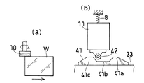
また、上記に図示した回転砥石(10)を用いた研磨装置(1)においては、研磨装置本体(2)の主軸(15)の方向と、スライド体(3)によるスライド方向と、退避用スライドガイド(21)によるスライド方向がすべて平行であるが、主軸(15)の方向を変えることによってワーク端面の研磨に用いるか、面取り研磨に用いるかを設定することができる。これは、ワーク(W)の設置状態との関係になるが、薄板状ワーク(W)の平面と平行な平面内に主軸(15)があればワーク端面用回転砥石(10A)となり、前記端面と隣接した第1または第2の面取りの角度をαとした場合、ワーク平面と主軸のなす角が±(90°−α)と同じにされ、かつ主軸(15)が第1の相対移動方向と直交するように配置されれば、第1または第2の面取り部研磨用の回転砥石(10B)(10C)となる(図9(a)参照)。なお、図9では、ワーク(W)の被研磨部と砥石(10A)(10B)(10C)の配置関係を示すに際し、砥石(10A)(10B)(10C)を円盤状に簡略表現している。ただし、第1または第2の面取り部研磨用の回転砥石(10B)(10C)を用いた研磨装置においては、モータ取付け台(12)の取り付け面が前記なす角に応じて傾斜した形状になるとともに、端面用、面取り用ともに主軸(15)の設置位置が適正な高さに変えられる。 Further, in the polishing apparatus (1) using the rotary grindstone (10) illustrated above, the direction of the main shaft (15) of the polishing apparatus body (2), the sliding direction by the slide body (3), and the slide for retraction The sliding directions by the guide (21) are all parallel, but by changing the direction of the main shaft (15), it can be set whether to use for polishing the end face of the workpiece or for chamfering polishing. This is related to the installation state of the workpiece (W), but if there is a spindle (15) in a plane parallel to the plane of the thin plate workpiece (W), it becomes a rotary grindstone (10A) for the workpiece end surface, and the end surface When the angle of the first or second chamfer adjacent to the surface is α, the angle between the workpiece plane and the main axis is the same as ± (90 ° −α), and the main axis (15) is the first relative movement direction. If it is arranged so as to be orthogonal to the rotating grindstone (10B) (10C) for polishing the first or second chamfered portion (see FIG. 9A). In addition, in FIG. 9, when showing the arrangement | positioning relationship between the to-be-polished part of a workpiece | work (W), and a grindstone (10A) (10B) (10C), a grindstone (10A) (10B) (10C) is simply expressed in disk shape. Yes. However, in the polishing apparatus using the rotating grindstone (10B) (10C) for polishing the first or second chamfered portion, the mounting surface of the motor mounting base (12) is inclined according to the angle formed by the above. At the same time, the installation position of the spindle (15) can be changed to an appropriate height for both end and chamfering.
なお、図示省略したが、外周面を研磨面とする回転砥石を使用する場合、砥石ベース(11)上に取り付けられたモータ取付け台(12)の向きを変更し(全体を90°回転)、スライド体(3)のスライド方向と直交する方向に主軸(15)が向くように(主軸と第1の相対移動方向が平行になるように)なすことで付勢手段(8)による付勢により、主軸(15)が左右方向に平行移動し、したがって研磨面である砥石外周面をワーク(W)に押し付けることができる。そして、外周面を研磨面とする回転砥石を用いた研磨装置においては、研磨装置本体(2)の主軸(15)の方向がスライド体(3)によるスライド方向と直交していることから、モータ(2)(主軸)の取付け高さを端面研磨用か面取り研磨用かによって変更するとともに、退避用スライドガイド(21)により決定する位置を変更することにより、ワーク端面用研磨装置か面取り部用研磨装置かに設定することができる。 Although not shown, when using a rotating grindstone whose outer peripheral surface is a polishing surface, the direction of the motor mount (12) mounted on the grindstone base (11) is changed (the whole is rotated by 90 °), By urging by the urging means (8) by making the main shaft (15) face the direction orthogonal to the sliding direction of the slide body (3) (so that the main shaft and the first relative movement direction are parallel). The main shaft (15) translates in the left-right direction, so that the grindstone outer peripheral surface, which is the polishing surface, can be pressed against the workpiece (W). In a polishing apparatus using a rotating grindstone having an outer peripheral surface as a polishing surface, the direction of the main shaft (15) of the polishing apparatus main body (2) is orthogonal to the sliding direction by the slide body (3). (2) By changing the mounting height of the (spindle) depending on whether it is for end face polishing or chamfering, and by changing the position determined by the retracting slide guide (21), the workpiece end face polishing machine or chamfering part It can be set to a polishing apparatus.
ワーク端面の研磨と面取り部の研磨とは、それぞれ別個に行ってももちろんよいが、図9(b)に示すように、ワーク(W)を水平に保持するとともに、ワーク端面の研磨を行う端面研磨用回転砥石(10A)、前記端面に隣接する一方の面側の面取りを行う第1面取り研磨用回転砥石(10B)、および前記端面に隣接する他方の面側の面取りを行う第2面取り研磨用回転砥石(10C)の3つの回転砥石(10A)(10B)(10C)を使用し、これらを有する研磨装置をワーク送り方向(第1の相対移動方向)上に配置することにより、第1の相対移動手段(7)による移動の過程で端面および両面取り部を研磨することができる。この際、ワーク保持手段に複数のワークを第1の相対移動方向に並べて保持させるようにすることにより、より一層研磨効率を上昇することができる。なお、図示した回転砥石(10)を使用する場合、第1または第2の面取り部研磨用の回転砥石(10B)(10C)は、可能な限り回転中心より離れた研磨面を利用し、それらとワークとの接触位置(研磨位置)が両回転砥石(10B)(10C)が接触しない範囲で可能な限り近づけるようにすることが好ましい。このようにすれば、一方向から回転砥石(10B)(10C)を押し付ける場合は、たわみの影響による割れ等の不良防止策が必要となるところ、ワークに生じるたわみの一部が第1と第2の面取り部研磨用回転砥石(10B)(10C)による押し付けにより相殺されるため、割れ等の不良防止策が軽減される。
Of course, the polishing of the workpiece end surface and the chamfered portion may be performed separately. However, as shown in FIG. 9B, the workpiece (W) is held horizontally and the workpiece end surface is polished. A polishing grindstone (10A), a first chamfering grindstone (10B) that chamfers one side adjacent to the end face, and a second chamfering grind that chamfers on the other face side adjacent to the end face By using three rotary whetstones (10A), (10B), and (10C) of a rotary whetstone for a machine (10C) and arranging a polishing apparatus having these on the workpiece feed direction (first relative movement direction), the first In the process of movement by the relative movement means (7), the end face and the double-sided chamfered portion can be polished. At this time, the polishing efficiency can be further increased by causing the workpiece holding means to hold a plurality of workpieces side by side in the first relative movement direction. When using the illustrated rotating grindstone (10), the rotating grindstone (10B) (10C) for polishing the first or second chamfered portion uses a polishing surface as far as possible from the rotation center, It is preferable that the contact position (polishing position) between the workpiece and the workpiece be as close as possible within a range in which the rotary grindstones (10B) and (10C) do not contact each other. In this way, when the rotating grindstone (10B) (10C) is pressed from one direction, it is necessary to take measures to prevent defects such as cracks due to the effect of deflection. Since this is offset by pressing with the rotating grindstones (10B) and (10C) for
さらにまた、図示省略したが、ワーク(W)の被研磨部が平行線状の第1の辺と第2の辺とを有している場合には、第1の辺を研磨する第1回転砥石(10)と第2の辺を研磨する回転砥石(10)とが対向状に配置されるとともに、前記第2の相対移動手段(9)が第1および第2の辺の近傍にそれぞれ設けられている構成とすることにより、第1の相対移動手段(7)による移動の過程でワーク(W)の対向する2辺を同時に研磨することもできる。この場合も、端面および面取り部用の研磨装置を第1の相対移動方向に並べてもよい。 Furthermore, although not shown, when the part to be polished of the workpiece (W) has a first side and a second side that are parallel lines, the first rotation for polishing the first side. A grindstone (10) and a rotating grindstone (10) for polishing the second side are arranged opposite to each other, and the second relative movement means (9) is provided in the vicinity of the first and second sides, respectively. By adopting such a configuration, two opposing sides of the workpiece (W) can be simultaneously polished in the course of movement by the first relative movement means (7). Also in this case, the polishing apparatus for the end face and the chamfered portion may be arranged in the first relative movement direction.
第1の相対移動手段(7)と組み合わされて使用されるワーク保持手段(6)としては、方形のワークの4辺がはみ出るようにワークを保持するものとすることができ、この場合に、第1の相対移動手段を研磨装置本体側にのみ設けるとともに、各辺の近傍にそれぞれ専用の研磨装置本体を配置することにより、4辺を同時に研磨することができる。この場合でも、ワーク端面用研磨装置本体と第1および第2面取り用研磨装置本体とを各辺に設けるようにしてもよい。これに代えて、ワーク保持手段のみに第1の相対移動手段を設けるとともに、ワーク保持手段に回転手段をさらに設け、第1の相対移動手段により研磨装置本体を通過したところで、回転手段によりワークを90°回転させ、未研磨の辺を研磨装置本体側に向けるようにすることもできる。この回転手段の回転軸は、略正方形のワークの場合、ワーク保持手段の中心に設けることが好ましい。 As the work holding means (6) used in combination with the first relative moving means (7), the work can be held so that the four sides of the rectangular work protrude, and in this case, By providing the first relative moving means only on the polishing apparatus main body side and arranging a dedicated polishing apparatus main body in the vicinity of each side, four sides can be polished simultaneously. Even in this case, the workpiece end surface polishing apparatus main body and the first and second chamfering polishing apparatus main bodies may be provided on each side. Instead of this, the first relative moving means is provided only in the work holding means, the rotating means is further provided in the work holding means, and the work is moved by the rotating means when the first relative moving means passes through the polishing apparatus main body. It is also possible to rotate 90 ° so that the unpolished side faces the polishing apparatus main body. In the case of a substantially square workpiece, the rotation axis of the rotation unit is preferably provided at the center of the workpiece holding unit.
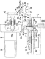
図10および図11は、この発明の研磨装置の第2実施形態を示している。この研磨装置(1)は、第1実施形態のものと付勢手段が異なるのみであり、第1実施形態と同じ構成には同じ符号を付してその説明を省略する。また、前後・左右も第1実施形態の研磨装置の各図に合わせている。 10 and 11 show a second embodiment of the polishing apparatus of the present invention. This polishing apparatus (1) is different from that of the first embodiment only in the urging means, and the same components as those in the first embodiment are denoted by the same reference numerals and description thereof is omitted. Further, the front, rear, left and right are also matched with the drawings of the polishing apparatus of the first embodiment.
同図に示すように、付勢手段(50)は、砥石ベース(11)の左端部に後方(砥石ベース面に含まれスライド方向と直交する方向)突出状に設けられたワイヤロープ連結用ブラケット(53)と、固定台(4)の上板後面に下端部が固定されたL字型プーリサポート(51)と、プーリサポート(51)に前記ブラケット(53)よりもワーク側で回転可能に支持されたプーリ(52)と、前記ブラケット(53)に一端が固定されてプーリ(52)に掛けられたワイヤロープ(54)と、ワイヤロープ(54)の他端に吊り下げられたウエイトホルダ(55)に載せられたカウンタウエイト(重錘)(56)とを有している。これにより、砥石ベース(11)はカウンタウエイト(56)の自重(砥石ベース(11)が左右に移動しても常に一定)によって右方に付勢されている。したがって、カウンタウエイト(56)の重量を変更することにより、回転砥石(10)のワーク(W)への付勢力を調整することができる。なお、L字型プーリサポート(51)は、砥石ユニット架台(5)に設けてもよい。 As shown in the figure, the urging means (50) is a wire rope coupling bracket provided in a protruding manner in the rear end (direction perpendicular to the sliding direction included in the grinding wheel base surface) at the left end of the grinding wheel base (11). (53), an L-shaped pulley support (51) whose lower end is fixed to the rear surface of the upper plate of the fixed base (4), and the pulley support (51) can be rotated on the workpiece side from the bracket (53). A supported pulley (52), a wire rope (54) that is fixed to the bracket (53) at one end and hung on the pulley (52), and a weight holder suspended from the other end of the wire rope (54) And a counterweight (56) mounted on (55). Thereby, the grindstone base (11) is urged to the right by the weight of the counterweight (56) (always constant even if the grindstone base (11) moves left and right). Therefore, by changing the weight of the counterweight (56), the urging force of the rotating grindstone (10) to the workpiece (W) can be adjusted. The L-shaped pulley support (51) may be provided on the grindstone unit base (5).
第1および第2実施形態において、砥石の回転方向に飛ぶ研磨屑(微細な粉)を一端に吸気孔、他端に吸気手段(排気手段)を有するフレキシブル配管からなる研磨屑収集手段で収集すると、研磨屑の飛散を無くすことができ、研磨屑のワークへの吸着を防ぐことができる。この際、送気を行う送気手段によって前記回転方向で研磨位置に向けて送気することにより、研磨屑を対向する前記吸気孔に一層効果的に導くことができる。 In the first and second embodiments, when polishing scraps (fine powder) flying in the rotation direction of the grindstone are collected by polishing scrap collecting means comprising a flexible pipe having an intake hole at one end and an intake means (exhaust means) at the other end. Further, it is possible to eliminate the scattering of the polishing dust and to prevent the polishing dust from adsorbing to the workpiece. At this time, by supplying air toward the polishing position in the rotation direction by the air supply means for supplying air, the polishing debris can be more effectively guided to the opposed suction holes.
また、第1および第2実施形態の研磨装置では、回転砥石(10)を弾性砥石とするとともに、付勢手段(8)(50)の定圧用ばね(38)またはカウンタウエイト(56)によりワーク(W)の被研磨部に作用する圧力が適度であって略定圧となる圧力制御を行っていることから、位置制御と異なり、砥石(10)とワーク(W)との間に作用する力によって砥石(10)の回転が停止させられるというような問題が起こることがないので、砥石(10)の周速度を0.5m/s〜2.0m/sの範囲の低速で利用し適切に研磨することができる。これにより、剛性砥石の高速回転では、ワーク(W)が強制的に引っ掻かれるため研磨屑が塊となるのに対し、微細な粉の研磨屑となり、砥石(10)の砥粒の凹凸がそのままワーク(W)に転写されることがなく、また、研磨屑の飛散の際に有するエネルギーも小さいものとなる。また、砥石(10)とワーク(W)とにかかる負荷が小さいため、位置制御で高速回転させる従来のものに比べて、発熱量が十分小さくなり、また、研磨屑が微細な粉であるため、吸気等で収集可能であり、冷却や洗浄等に用いる水などの回路パターン等処理された面が嫌う物質を使う必要がなくなるので、従来は研磨されていなかった回路パターン等処理されたワーク(W)の研磨を行うことができる。このため、この発明は、水等を利用する研磨方法(湿式)とは異なり、ドライな研磨方法(乾式)を提供するためのドライ研磨装置ということができる。 In the polishing apparatus of the first and second embodiments, the rotary grindstone (10) is an elastic grindstone, and the workpiece is fixed by the constant pressure spring (38) or the counterweight (56) of the biasing means (8) (50). Unlike the position control, the force acting between the grindstone (10) and the workpiece (W) is controlled because the pressure acting on the part to be polished of (W) is moderate and is almost constant pressure. Therefore, there is no problem that the rotation of the grindstone (10) is stopped. Therefore, the peripheral speed of the grindstone (10) is appropriately used at a low speed in the range of 0.5 m / s to 2.0 m / s. Can be polished. As a result, when the rigid grindstone is rotated at high speed, the workpiece (W) is forcibly scratched, so that the abrasive debris is agglomerated, whereas the fine debris becomes debris, and the abrasive grains of the grindstone (10) are uneven. It is not transferred to the workpiece (W) as it is, and the energy it has at the time of polishing dust scattering is small. In addition, because the load on the grinding wheel (10) and the workpiece (W) is small, the amount of heat generation is sufficiently small compared to the conventional one that rotates at high speed with position control, and the polishing dust is fine powder Since it is not necessary to use substances that can be collected by intake air, etc., and processed surfaces such as circuit patterns such as water used for cooling and cleaning, circuit patterns that have not been polished in the past have been processed ( W) can be polished. For this reason, this invention can be said to be a dry polishing apparatus for providing a dry polishing method (dry type), unlike a polishing method (wet type) using water or the like.
ワーク、特にウェハやガラス薄板の辺の端面や端面に隣接する面取り部の研磨に有効であり、さらに、それらワークのうち特に回路パターン等処理済みの取扱いに注意を要するワークの研磨装置として有効であって、従来の位置制御型の研磨装置に置き換え可能である。 Effective for polishing workpieces, especially chamfers adjacent to end faces and end faces of wafers and glass thin plates. In addition, it is effective as a polishing machine for workpieces that require special handling of circuit patterns, etc. Therefore, it can be replaced with a conventional position control type polishing apparatus.
(1) 研磨装置
(2) 研磨装置本体
(6) ワーク保持手段
(7) 第1の相対移動手段
(8) 付勢手段
(9) 第2の相対移動手段
(10) 回転砥石
(11) 砥石ベース(砥石を支持する台)
(20) 第3の相対移動手段
(27) ワーク台(ワークを支持する台)
(34) 支持体
(35) ばね圧力調整用おねじ部材
(36) 円柱状ばねガイド
(37) ばね受け
(38) 定圧用ばね
(39) ストッパ
(41) 線状カム
(41a)(41c) 凸部
(41b) 凹部
(42) ガイドローラ
(50) 付勢手段
(51) プーリサポート
(52) プーリ
(54) ワイヤロープ
(55) ウエイトホルダ
(56) カウンタウエイト
(W) ワーク
(1) Polishing equipment
(2) Polishing device body
(6) Workpiece holding means
(7) First relative movement means
(8) Energizing means
(9) Second relative movement means
(10) Rotary grinding wheel
(11) Whetstone base (table that supports the whetstone)
(20) Third relative movement means
(27) Work table (table that supports the workpiece)
(34) Support
(35) Male thread member for spring pressure adjustment
(36) Cylindrical spring guide
(37) Spring support
(38) Constant pressure spring
(39) Stopper
(41) Linear cam
(41a) (41c) Convex
(41b) Recess
(42) Guide roller
(50) Energizing means
(51) Pulley support
(52) Pulley
(54) Wire rope
(55) Weight holder
(56) Counterweight
(W) Workpiece
Claims (7)
第2の相対移動手段を支持してこれを退避位置と研磨位置とに移動させる第3の相対移動手段と、第2の相対移動手段に設けられて回転砥石とワークの接触する圧力が略定圧となるように回転砥石またはワークを付勢する付勢手段とをさらに備えており、
第2の相対移動手段は、研磨装置本体およびワーク保持手段のいずれか一方に設けられかつ第1の移動方向に沿って凹凸が形成された線状カムと、同他方に設けられて付勢手段の付勢力によって相対的に線状カムに接近する方向に付勢されているガイドローラとを有し、線状カムの凹凸は、ガイドローラが線状カムの凸部に位置した際にこれと接触することで、回転砥石とワークとの間に付勢方向の間隙が形成され、ガイドローラが線状カムの凹部に位置した際にこれと非接触となることで、回転砥石とワークとの間に付勢手段の付勢力が作用するようになされていることを特徴とする研磨装置。 A polishing apparatus body having a rotating grindstone made of an elastic grindstone in which abrasive grains are held on an elastic body, a work holding means for holding a work, and a contact position between a workpiece to be polished and a grindstone from a polished position to an unpolished position A first relative movement means that moves relative to the first position, and a second relative movement means that moves the grindstone position to a workpiece contact position and a workpiece non-contact position as the first relative movement means moves. In a polishing apparatus for polishing the peripheral edge of a thin plate workpiece,
The third relative movement means for supporting the second relative movement means and moving the second relative movement means to the retreat position and the polishing position, and the pressure at which the rotary grindstone and the workpiece contact with each other are substantially constant pressure. further comprising a biasing means for biasing the grinding wheel or the workpiece so that,
The second relative moving means is a linear cam provided on one of the polishing apparatus main body and the work holding means and having irregularities formed along the first moving direction, and an urging means provided on the other. The guide roller is biased in a direction approaching the linear cam relatively by the biasing force of the linear cam, and the unevenness of the linear cam is different from that when the guide roller is positioned on the convex portion of the linear cam. By contacting, a gap in the urging direction is formed between the rotating grindstone and the workpiece, and when the guide roller is positioned in the concave portion of the linear cam, it is not in contact with the rotating grindstone and the workpiece. A polishing apparatus characterized in that a biasing force of a biasing means acts between them .
Priority Applications (1)
| Application Number | Priority Date | Filing Date | Title |
|---|---|---|---|
| JP2003287338A JP4143763B2 (en) | 2003-08-06 | 2003-08-06 | Polishing equipment |
Applications Claiming Priority (1)
| Application Number | Priority Date | Filing Date | Title |
|---|---|---|---|
| JP2003287338A JP4143763B2 (en) | 2003-08-06 | 2003-08-06 | Polishing equipment |
Publications (2)
| Publication Number | Publication Date |
|---|---|
| JP2005052944A JP2005052944A (en) | 2005-03-03 |
| JP4143763B2 true JP4143763B2 (en) | 2008-09-03 |
Family
ID=34366342
Family Applications (1)
| Application Number | Title | Priority Date | Filing Date |
|---|---|---|---|
| JP2003287338A Expired - Fee Related JP4143763B2 (en) | 2003-08-06 | 2003-08-06 | Polishing equipment |
Country Status (1)
| Country | Link |
|---|---|
| JP (1) | JP4143763B2 (en) |
Families Citing this family (13)
| Publication number | Priority date | Publication date | Assignee | Title |
|---|---|---|---|---|
| CN101167148B (en) * | 2005-04-27 | 2013-02-27 | 株式会社村田制作所 | Solid state electrolytic capacitor |
| WO2006118145A1 (en) * | 2005-04-27 | 2006-11-09 | Showa Denko K. K. | Solid state electrolytic capacitor |
| JP4895172B2 (en) * | 2005-04-27 | 2012-03-14 | 株式会社村田製作所 | Solid electrolytic capacitor and manufacturing method thereof |
| JP5305214B2 (en) * | 2006-10-06 | 2013-10-02 | 日本電気硝子株式会社 | End face processing method of plate glass |
| KR101811903B1 (en) * | 2010-07-08 | 2017-12-22 | 아사히 가라스 가부시키가이샤 | Glass substrate end surface evaluation method, glass substrate end surface processing method, and glass substrate |
| KR101260953B1 (en) | 2010-07-29 | 2013-05-06 | 주식회사 케이엔제이 | Work edge grinding apparatus and method using the same |
| CN104831606B (en) * | 2015-05-22 | 2016-12-07 | 重庆市巴南区前进机械厂 | Stable and can the edge-neatening apparatus of road tartar on garden path of dust suction and using method thereof |
| CN104947572B (en) * | 2015-05-22 | 2016-12-07 | 邬时伟 | Garden path edge-neatening apparatus with dust cover and using method thereof |
| CN104988841B (en) * | 2015-05-22 | 2017-01-04 | 邬时伟 | The garden path edge-neatening apparatus of adjustable height and using method thereof |
| CN104889850A (en) * | 2015-05-22 | 2015-09-09 | 楼天涯 | Park road curbstone trimming device provided with heat dissipating fins and using method thereof |
| JP6178369B2 (en) * | 2015-09-07 | 2017-08-09 | 株式会社チップトン | Siding board grinding machine |
| CN109499984B (en) * | 2018-10-13 | 2022-03-18 | 广东嗨学云教育科技有限公司 | Universal manufacturing device for integrated circuit |
| CN110695804B (en) * | 2019-11-18 | 2020-06-12 | 福州高新区磊莎玻璃有限公司 | Multidirectional glass edge grinding device |
-
2003
- 2003-08-06 JP JP2003287338A patent/JP4143763B2/en not_active Expired - Fee Related
Also Published As
| Publication number | Publication date |
|---|---|
| JP2005052944A (en) | 2005-03-03 |
Similar Documents
| Publication | Publication Date | Title |
|---|---|---|
| JP4143763B2 (en) | Polishing equipment | |
| US6402588B1 (en) | Polishing apparatus | |
| US6685539B1 (en) | Processing tool, method of producing tool, processing method and processing apparatus | |
| EP2762272B1 (en) | Wafer polishing apparatus and method | |
| KR100692357B1 (en) | Method and apparatus for leveling process and manufacturing method for semiconductor device | |
| JPH0890401A (en) | Wafer edge finishing device | |
| CN107791115B (en) | Processing device | |
| KR20070098416A (en) | Planarization apparatus and method for semiconductor wafer | |
| JP2007210074A (en) | Grinding device, polishing device, grinding method and polishing method | |
| JP2011224680A (en) | Polishing method and device | |
| KR20100115819A (en) | Polishing apparatus, polishing auxiliary apparatus and polishing method | |
| JP4487353B2 (en) | Polishing apparatus and polishing method | |
| JP2009016759A (en) | Device for polishing semiconductor wafer end face and polishing head used for the same | |
| KR20170108813A (en) | Laminated sheet grinding apparatus and laminated sheet grinding method | |
| JP2004050345A (en) | Processing device for outer periphery of thin plate-like work | |
| JP4977493B2 (en) | Dressing method and dressing tool for grinding wheel | |
| JP2008018502A (en) | Substrate polishing device, substrate polishing method, and substrate treating device | |
| JP4472694B2 (en) | Straight type polishing method | |
| JP2000158306A (en) | Both-surface grinding device | |
| JP2009004579A (en) | Polishing apparatus for semiconductor wafer notch end face, and polishing head used for the same | |
| JP6495117B2 (en) | CMP polishing apparatus and CMP polishing method | |
| JP2009125873A (en) | Double-sided polishing device | |
| KR102078342B1 (en) | Diamond conditioner with adjustable contact area | |
| CN102101257B (en) | Substrate end surface grinding device | |
| JP4205263B2 (en) | Automatic lapping apparatus and substrate polishing method using the same |
Legal Events
| Date | Code | Title | Description |
|---|---|---|---|
| A621 | Written request for application examination |
Free format text: JAPANESE INTERMEDIATE CODE: A621 Effective date: 20060223 |
|
| A977 | Report on retrieval |
Free format text: JAPANESE INTERMEDIATE CODE: A971007 Effective date: 20070914 |
|
| A131 | Notification of reasons for refusal |
Free format text: JAPANESE INTERMEDIATE CODE: A131 Effective date: 20070925 |
|
| A521 | Request for written amendment filed |
Free format text: JAPANESE INTERMEDIATE CODE: A523 Effective date: 20071121 |
|
| TRDD | Decision of grant or rejection written | ||
| A01 | Written decision to grant a patent or to grant a registration (utility model) |
Free format text: JAPANESE INTERMEDIATE CODE: A01 Effective date: 20080507 |
|
| A01 | Written decision to grant a patent or to grant a registration (utility model) |
Free format text: JAPANESE INTERMEDIATE CODE: A01 |
|
| A61 | First payment of annual fees (during grant procedure) |
Free format text: JAPANESE INTERMEDIATE CODE: A61 Effective date: 20080602 |
|
| R150 | Certificate of patent or registration of utility model |
Ref document number: 4143763 Country of ref document: JP Free format text: JAPANESE INTERMEDIATE CODE: R150 Free format text: JAPANESE INTERMEDIATE CODE: R150 |
|
| FPAY | Renewal fee payment (event date is renewal date of database) |
Free format text: PAYMENT UNTIL: 20110627 Year of fee payment: 3 |
|
| FPAY | Renewal fee payment (event date is renewal date of database) |
Free format text: PAYMENT UNTIL: 20110627 Year of fee payment: 3 |
|
| FPAY | Renewal fee payment (event date is renewal date of database) |
Free format text: PAYMENT UNTIL: 20120627 Year of fee payment: 4 |
|
| FPAY | Renewal fee payment (event date is renewal date of database) |
Free format text: PAYMENT UNTIL: 20130627 Year of fee payment: 5 |
|
| LAPS | Cancellation because of no payment of annual fees |