EP2591908B1 - Verfahren und Vorrichtung zur Herstellung eines Wickelbandes - Google Patents
Verfahren und Vorrichtung zur Herstellung eines Wickelbandes Download PDFInfo
- Publication number
- EP2591908B1 EP2591908B1 EP12191368.5A EP12191368A EP2591908B1 EP 2591908 B1 EP2591908 B1 EP 2591908B1 EP 12191368 A EP12191368 A EP 12191368A EP 2591908 B1 EP2591908 B1 EP 2591908B1
- Authority
- EP
- European Patent Office
- Prior art keywords
- roll
- cross
- circumferentially extending
- monofilament strand
- sectional shape
- Prior art date
- Legal status (The legal status is an assumption and is not a legal conclusion. Google has not performed a legal analysis and makes no representation as to the accuracy of the status listed.)
- Active
Links
Images


Classifications
-
- B—PERFORMING OPERATIONS; TRANSPORTING
- B29—WORKING OF PLASTICS; WORKING OF SUBSTANCES IN A PLASTIC STATE IN GENERAL
- B29C—SHAPING OR JOINING OF PLASTICS; SHAPING OF MATERIAL IN A PLASTIC STATE, NOT OTHERWISE PROVIDED FOR; AFTER-TREATMENT OF THE SHAPED PRODUCTS, e.g. REPAIRING
- B29C43/00—Compression moulding, i.e. applying external pressure to flow the moulding material; Apparatus therefor
- B29C43/22—Compression moulding, i.e. applying external pressure to flow the moulding material; Apparatus therefor of articles of indefinite length
-
- B—PERFORMING OPERATIONS; TRANSPORTING
- B29—WORKING OF PLASTICS; WORKING OF SUBSTANCES IN A PLASTIC STATE IN GENERAL
- B29C—SHAPING OR JOINING OF PLASTICS; SHAPING OF MATERIAL IN A PLASTIC STATE, NOT OTHERWISE PROVIDED FOR; AFTER-TREATMENT OF THE SHAPED PRODUCTS, e.g. REPAIRING
- B29C67/00—Shaping techniques not covered by groups B29C39/00 - B29C65/00, B29C70/00 or B29C73/00
- B29C67/02—Moulding by agglomerating
- B29C67/04—Sintering
-
- H—ELECTRICITY
- H01—ELECTRIC ELEMENTS
- H01B—CABLES; CONDUCTORS; INSULATORS; SELECTION OF MATERIALS FOR THEIR CONDUCTIVE, INSULATING OR DIELECTRIC PROPERTIES
- H01B3/00—Insulators or insulating bodies characterised by the insulating materials; Selection of materials for their insulating or dielectric properties
- H01B3/18—Insulators or insulating bodies characterised by the insulating materials; Selection of materials for their insulating or dielectric properties mainly consisting of organic substances
- H01B3/30—Insulators or insulating bodies characterised by the insulating materials; Selection of materials for their insulating or dielectric properties mainly consisting of organic substances plastics; resins; waxes
- H01B3/44—Insulators or insulating bodies characterised by the insulating materials; Selection of materials for their insulating or dielectric properties mainly consisting of organic substances plastics; resins; waxes vinyl resins; acrylic resins
- H01B3/443—Insulators or insulating bodies characterised by the insulating materials; Selection of materials for their insulating or dielectric properties mainly consisting of organic substances plastics; resins; waxes vinyl resins; acrylic resins from vinylhalogenides or other halogenoethylenic compounds
- H01B3/445—Insulators or insulating bodies characterised by the insulating materials; Selection of materials for their insulating or dielectric properties mainly consisting of organic substances plastics; resins; waxes vinyl resins; acrylic resins from vinylhalogenides or other halogenoethylenic compounds from vinylfluorides or other fluoroethylenic compounds
-
- B—PERFORMING OPERATIONS; TRANSPORTING
- B29—WORKING OF PLASTICS; WORKING OF SUBSTANCES IN A PLASTIC STATE IN GENERAL
- B29C—SHAPING OR JOINING OF PLASTICS; SHAPING OF MATERIAL IN A PLASTIC STATE, NOT OTHERWISE PROVIDED FOR; AFTER-TREATMENT OF THE SHAPED PRODUCTS, e.g. REPAIRING
- B29C55/00—Shaping by stretching, e.g. drawing through a die; Apparatus therefor
- B29C55/30—Drawing through a die
-
- B—PERFORMING OPERATIONS; TRANSPORTING
- B29—WORKING OF PLASTICS; WORKING OF SUBSTANCES IN A PLASTIC STATE IN GENERAL
- B29K—INDEXING SCHEME ASSOCIATED WITH SUBCLASSES B29B, B29C OR B29D, RELATING TO MOULDING MATERIALS OR TO MATERIALS FOR MOULDS, REINFORCEMENTS, FILLERS OR PREFORMED PARTS, e.g. INSERTS
- B29K2027/00—Use of polyvinylhalogenides or derivatives thereof as moulding material
- B29K2027/12—Use of polyvinylhalogenides or derivatives thereof as moulding material containing fluorine
- B29K2027/18—PTFE, i.e. polytetrafluoroethylene, e.g. ePTFE, i.e. expanded polytetrafluoroethylene
-
- B—PERFORMING OPERATIONS; TRANSPORTING
- B29—WORKING OF PLASTICS; WORKING OF SUBSTANCES IN A PLASTIC STATE IN GENERAL
- B29K—INDEXING SCHEME ASSOCIATED WITH SUBCLASSES B29B, B29C OR B29D, RELATING TO MOULDING MATERIALS OR TO MATERIALS FOR MOULDS, REINFORCEMENTS, FILLERS OR PREFORMED PARTS, e.g. INSERTS
- B29K2995/00—Properties of moulding materials, reinforcements, fillers, preformed parts or moulds
- B29K2995/0003—Properties of moulding materials, reinforcements, fillers, preformed parts or moulds having particular electrical or magnetic properties, e.g. piezoelectric
- B29K2995/0007—Insulating
Definitions
- the invention relates to a method for producing a winding tape according to the preamble of claim 1 and to an associated apparatus according to the preamble of claim 9.
- winding tapes of sinterable plastics such as polytetrafluoroethylene are known from the prior art.
- Such winding tapes are preferably used for the insulation of electrical cables and wires.
- the winding tapes usually produced by rolling are usually wound in a multi-layered or overlapping manner helically and the edges of the winding tapes are connected to the underlying layers, for example, by subsequent sintering.
- the insulating sleeve produced from a winding tape is almost free of columns and compact and that the surface is smooth and has no abutting edges, which are points of attack for external mechanical forces.
- a non-sintered wrapping tape having a plano-convex cross-sectional shape in which an upper limit line is curved and a lower limit line is straight.
- the band thickness in the middle region of the band is reinforced compared to the edges.
- a method for producing a winding tape is specified with a deviating from the rectangular shape cross-sectional shape. So revealed the DE 41 03 540 C2 For example, a method in which first a band material is formed with at least twice the width of the winding band and then separated by a squeeze separation, whereby winding tapes are produced with a tapered to the edges cross-sectional shape.
- the DE 102 01 833 A1 provides a method in which an initially extruded from a blank round cord with a circular cross-section is rolled into a tape.
- the round cord is pressure-loaded in a radial direction so rolled that the remaining material in the middle part of the band is greater than the amount of material remaining to the band edges.
- Essential for this method is that during the rolling process, the surface of at least one roller is deformed under pressure.
- a disadvantage of the in the DE 102 01 833 A1 specified method is on the one hand that only round cords can be rolled with a circular cross-section, otherwise there may be irregularities in thickness and width of the tape.
- uniformity and quality of the winding tape are highly dependent on the material properties of the roll, namely on their elasticity. If, for example, the elasticity of the roll decreases as a result of material aging, this can adversely affect both the shape and the quality of the winding strip
- the object of the present invention is therefore to improve the method known from the prior art.
- the object is achieved on the basis of the features of the preamble of claim 1 by its characterizing features.
- the present invention describes a method for producing a winding tape, in which a cylindrical blank is first pressed from a mixture of materials, preferably a mixture of unsintered polytetrafluoroethylene powder and a lubricant. In a next step, the blank is then pressed to a smaller dimensioned monofilament strand having a predetermined cross-sectional shape. The monofilament strand is then rolled in a calender roll arrangement with at least one first and one second rigid roll to form a winding band.
- the essential aspect of the method according to the invention is to be seen in that the monofilament strand is fed to a circumferential recess provided on the peripheral surface of the at least second roller and to the latter by means of both rigid rollers Winding tape is rolled, that the winding tape at least partially assumes a predetermined by the recess of the at least second rigid roller and the peripheral surface of the first rigid roller shape.
- the cross-sectional shape of the extruded monofilament strand is approximately matched to the shape of the circumferential recess.
- the monofilament strand is inserted into the circumferential recess provided on the peripheral surface of the at least second roller.
- the recess of the second roller forms, together with the peripheral surface of the first roller, a cavity which can be virtually compared with a rolling or casting mold and ultimately forms the winding belt.
- the wrapping tape thus at least partially assumes the shape of the shape formed by the recess of the second roller and the peripheral surface of the first roller.
- rollers are rigid rollers and the roller material, preferably steel, is firm and resistant, the shape of the circumferential recess is consistent even under extreme conditions. Thus, for example, due to compressive stresses of the roller pair, no change in the surface is to be expected. This ensures a consistently consistent shape and quality of the winding tape. With the method according to the invention, therefore, a secure, stable and yet simple production process is provided, in particular even with extended service life or with long use of the rollers used.
- the cross-sectional shape of the monofilament strand which is first pressed out of the blank, matched to the shape of the depression, so that, for example, the relative increase in length and / or width of the monofilament strand during the rolling to the winding band can be predetermined and thus the factor can be defined or regulated for length and / or width increase.
- the circumferential recess provided on the peripheral surface of the at least second roller is supplied with a monofilament strand having a substantially oval cross-sectional shape or a monofilament strand having a substantially polygonal, preferably rectangular cross-sectional shape.
- a monofilament strand having a substantially oval cross-sectional shape or a monofilament strand having a substantially polygonal, preferably rectangular cross-sectional shape can be supplied with a monofilament strand having a substantially oval cross-sectional shape or a monofilament strand having a substantially polygonal, preferably rectangular cross-sectional shape.
- the shape of the circumferential recess of the at least second roller on the type, shape and size of the produced winding tape, as well as the desired factor for length and / or width increase monofilament strands of different cross-sectional shapes can be supplied.
- the cross-sectional size namely selected based on length and width.
- the ratio of width b to length I of the cross-section may preferably be in a range of 1: 1.05 to 1:10, more preferably in a range of 1: 1.1 to 1: 3, particularly preferred at 1: 2.
- the ratio of width b to length I can preferably be in a range of 1: 1 to 1:15, particularly preferably in a range of 1: 1 to 1:10, particularly preferably 1: 5.
- the extruded monofilament strand is preferably fed by means of a feeding and positioning device provided on the peripheral surface of the at least second roller circumferential recess, more preferably the monofilament strand is fed centrally, the "centric feed” in the context of the present invention will be briefly explained below .
- Each circumferential recess has in principle a bottom portion and wall portions and can be "cut” with a perpendicular to the longitudinal axis of the roller and through the bottom portion of the recess extending cutting plane transverse to the roller.
- This cutting plane represents a plane of symmetry of the depression or an axis of symmetry with respect to the cross-sectional shape of the depression.
- the feeding of the monofilament strand into the depressions of the roll with the aid of the feeding and positioning device takes place at an imaginary line of intersection of this symmetry or cutting plane with the bottom section of the Deepening, namely centric.
- the pressing pressure in the blank press can be determined via a pressure measuring and control device and kept at a predetermined value for the duration of a defined period.
- the pressed cylindrical blank after removal from the blank press optionally initially be inserted into a carrier and support sleeve.
- the support and support sleeve which may be formed, for example, in the form of a plexiglass tube, the blank can be supplied to the monofilament press in a particularly simple and handy manner.
- the Carrier and support sleeve is a practical and safe storage and storage option for blanks.
- the monofilament strand in the monofilament press is squeezed out by means of a nozzle with a predetermined outlet opening, wherein the pressing speed and / or the reduction ratio are regulated.
- a nozzle with a predetermined outlet opening, wherein the pressing speed and / or the reduction ratio are regulated.
- extrusion through nozzles is commonly referred to as extrusion.
- Extrusion is essentially a continuous process in which the material to be processed is forced through a special die, creating bodies of the cross-section of the nozzle of any length.
- the present invention also includes an apparatus for producing a winding tape according to the specified method.
- the apparatus comprises at least one blank press, at least one monofilament press with a nozzle having a predetermined outlet opening and a calender roll arrangement with at least one first and one second rigid roll, characterized in that at least the second rigid roll has at least one circumferential recess on its peripheral surface.
- the two rigid rollers are substantially cylindrical and preferably made of steel.
- the rigid rollers may be made of steel of different degrees of hardness.
- the rollers may have a surface coating.
- the first roller has a smooth surface, but may alternatively have peripheral recesses on its peripheral surface analogously to the second roller.
- at least the first roller is provided with a suitable drive.
- the second roller is either driven by the first roller or alternatively also has its own drive.
- the Calender roll assembly may include, for example, additional rolls such as a pickup, rewinder and guide rolls.
- the device additionally comprises a feeding and positioning device for feeding the extruded monofilament strand in the circumferential recess of the second roller.
- the nozzle of the monofilament press has an exit opening with a substantially oval cross-sectional shape, wherein the aspect ratio of length to width of the exit opening is in a range of 1.05: 1 to 2: 1.
- the nozzle has an outlet opening with a substantially polygonal, preferably rectangular cross section, wherein the aspect ratio of length to width of the outlet opening in a range of 1: 1 to 10: 1.
- two, three or more circumferential recesses are formed on the peripheral surface of the at least second roller, wherein the circumferential recesses are arranged distributed along a longitudinal axis of the roller and each circumferential recess has a predetermined cross-sectional shape.
- a cutting plane extending through the depression and oriented perpendicular to the longitudinal axis of the roll represents an axis of symmetry with respect to the cross-sectional shape of the depression.
- the cross section of the circumferential recess essentially has the shape of a circular segment or circular segment.
- the exact shape, the area and the size of the circular segment-shaped cross-section of the wells are freely selectable and there are thus wells in different shapes and sizes for rolling different sized winding tapes available.
- the cross section of the circumferential recesses may also be formed substantially polygonal with, for example, pointed corners.
- FIG. 1 in a schematic overview representation of the inventive method for producing a winding tape 1 shown in a first process step, a material mixture, preferably a mixture of unsintered Polytetrafluoroethylene powder, a lubricant and optionally one or more dyes by means of a filling device 8 filled in a blank press 2.
- a material mixture preferably a mixture of unsintered Polytetrafluoroethylene powder, a lubricant and optionally one or more dyes
- a filling device 8 filled in a blank press 2.
- a cylindrical blank 3 is produced.
- the pressing pressure of the blank 3 is preferably controlled by means of a pressure measuring and control device 12 and kept constant for a defined time.
- the blank press 2 is opened after the pressing of the blank 3 and the cylindrical blank 3 is inserted or pressed into a carrier and support sleeve 11.
- the support and support sleeve 11 is formed for example in the form of a tube and made of a plastic material, which is formed, for example, transparent.
- the support and support sleeve 11 is realized in the form of a plexiglass tube. For clarity, this step is in the FIG. 1 not explicitly shown.
- the blank can also be stored and stored until further processing.
- the blank 3 located in the Plexiglas tube 11 is in a further step of the method according to the invention (in the FIG. 1 shown behind the double arrow) of a monofilament press 4 comprising at least one nozzle 9, preferably a spray nozzle with a predetermined outlet opening 9a supplied.
- a monofilament press 4 comprising at least one nozzle 9, preferably a spray nozzle with a predetermined outlet opening 9a supplied.
- the plexiglass tube 11 is preferably placed in a horizontal orientation on corresponding brackets on the Monofilpresse 4 and the blank 3 is pushed out, for example by means of a slide or punch from the Plexiglas tube 11 and inserted for example via a corresponding insertion cylinder on the Monofilpresse 4 and in this way the Monofil 4 fed.
- a smaller-sized monofilament strand 7 is pressed out with a predetermined cross-sectional shape. It is preferably ensured that the pressing out of the monofilament strand 7 is carried out both with a defined speed and with a defined reduction ratio.
- a monofilament strand 7 having a substantially oval cross-sectional shape or a monofilament strand 7 having a substantially polygonal, particularly preferably rectangular, cross-sectional shape is pressed out.
- FIGS. 3a to 3c Various possible cross-sectional shapes of the extruded monofilament strand are in the FIGS. 3a to 3c shown.
- the monofilament strand 7 is provided for this purpose by a circumferential recess 6 (in FIG. 1) provided on the peripheral surface of the at least second roller 5b FIG. 2 shown) and by means of both rigid rollers 5a, 5b so rolled to the winding tape 1 that the winding tape 1 at least partially assumes a predetermined by the recess 6 of the at least second roller 5b and the peripheral surface of the first roller 5a form.
- the cross-sectional shape of the extruded monofilament strand 7 is approximately matched to the shape of the recess 6.
- the feeding of the monofilament strand 7 in the circumferential recess 6 of the second roller 5b of the calender roll assembly 5 is preferably carried out by means of a feeding and positioning device 10, namely a guide wedge.
- a feeding and positioning device 10 Via the guide wedge 10, the monofilament strand 7 can be supplied at a precisely defined position of the recess 6 on the circumferential surface of the second roller 5b.
- the monofilament strand 7 is centered with the aid of the feeding and positioning device 10 in a corresponding circumferential recess 6 on the peripheral surface of the second roller 5b, as it is known from FIG. 2 and the associated description.
- both rollers 5a, 5b are steel rollers, wherein the first roller 5a is cylindrical and has a drive and the second roller 5b is formed as a shaping roller with circumferential recesses 6.
- the second roller 5b additionally has a plastic insert for slip control.
- the calender roll arrangement 5 of the illustrated example comprises, in addition to the first and second rolls 5a, 5b, in addition a pickup 5c and a rewinder 5d with guide roll 5e for winding up the finished winding tape 1.
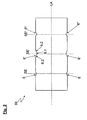
- FIG. 2 is a schematic longitudinal sectional view through the forming roller 5b of FIG. 1 shown.
- the roller 5b has with its longitudinal axis LA three peripheral depressions 6, 6 ', 6 ", which are arranged and distributed along the longitudinal axis LA of the roller 5b, the circumferential recesses 6, 6 ', 6 ", which essentially have a bottom section 6.1 and a wall section 6.2, differ in cross-sectional size and shape, with all cross-sectional shapes of the three recesses 6, 6', 6" of the illustrated example having approximately the shape of a circular section ,
- a perpendicular to the longitudinal axis LA of the roller 5b and through the bottom section 6.1 of the recesses 6, 6 ', 6 "extending cutting plane SE, SE', SE” across the roller 5b represents a plane of symmetry of the recesses 6, 6 ', 6 "and an axis of symmetry with respect to the cross-sectional shape of the recesses 6, 6 ', 6 ".
- the inventive supply of the monofilament strand 7 in the recesses 6, 6', 6" of the roller 5b by means of the feeding and positioning device 10 takes place at an imaginary cutting line of Symmetry or sectional planes SE, SE ', SE "with the bottom sections 6.1 of the recesses 6, 6', 6", namely centrally into the recesses 6, 6 ', 6 ".
- the monofilament strand 7 can be centrally introduced into a correspondingly required recess 6, 6 ', 6 "of the roll 5b with the aid of the feeding and positioning device 10.
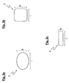
- FIGS. 3a to 3c are cross-sectional views of various embodiments of madeffesster monofilament strands 7 shown.
- the cross-sectional shape of the extruded monofilament strand 7 is approximated to the shape of the circumferential recess 6 of the at least second roller 5b, so that the rolling can be performed effectively by the rollers 5a, 5b in an optimized manner.
- the cross-sectional shape of the monofilament strand is determined by the shape of the outlet opening 9a of the nozzle 9, wherein a length I of the cross section of the monofilament strand 7 at the same time the length I of the outlet opening 9a of the nozzle 9 and a width b of the cross section of the monofilament strand 7 at the same time the width b of the outlet opening 9a of the nozzle 9 represents.
- a monofilament strand 7 is shown having a substantially oval cross-sectional shape.
- the ratio of width b to length I is preferably in a range of 1: 1.05 to 1: 5, more preferably in a range of 1: 1.1 to 1: 3, in the example shown, the ratio of width b to Length I 1: 2.
- the FIGS. 3b and 3c show examples of monofilament strands 7 with approximately rectangular cross-sectional shape, wherein the ratio of width b to length I preferably in a range of 1: 1 to 1:15, more preferably in a range of 1: 1 to 1:10, in the example shown of the FIG. 3b the ratio of width b to length I is 1: 1, in the example of Figure 3c it is 1: 5.
- FIG. 4 shows a cross section of a method according to the invention of FIG. 1
- the monofilament strand 7 is rolled out to the winding band 1 in such a way that the winding band 1 at least partially assumes a shape predetermined by the recess 6 of the at least second roller 5b and the circumferential surface of the first roller 5a.
- the winding tape 1 of the illustrated example has a substantially plano-convex cross-sectional shape with a curved and a smooth side.
- the plano-convex cross-sectional shape is determined by the predetermined by the recess 6 of the second rigid roller 5b and the peripheral surface of the rigid and cylindrical, smooth first roller 5a form.
- the wrapping tape 1 has a thicker central region 1 'and two thinner edge regions 1 "bordering it.
- the edge regions 1" increasingly flatten outwards and finally terminate in the winding tape edges 1.1.
- the thickness d in the central region 1 ' is preferably between 30 ⁇ m and 200 ⁇ m, and the thickness d in the edge region 1 "between 5 ⁇ m and 30 ⁇ m
- the winding tape edges 1.1 particularly preferably have a thickness d of less than or equal to 5 ⁇ m and preferably run with a thickness d going from 0 to ..
Landscapes
- Engineering & Computer Science (AREA)
- Mechanical Engineering (AREA)
- Physics & Mathematics (AREA)
- Spectroscopy & Molecular Physics (AREA)
- Casting Or Compression Moulding Of Plastics Or The Like (AREA)
- Treatment Of Fiber Materials (AREA)
- Spinning Methods And Devices For Manufacturing Artificial Fibers (AREA)
- Paper (AREA)
- Auxiliary Devices For And Details Of Packaging Control (AREA)
Priority Applications (3)
| Application Number | Priority Date | Filing Date | Title |
|---|---|---|---|
| SI201230672A SI2591908T1 (sl) | 2011-11-11 | 2012-11-06 | Postopek in naprava za proizvodnjo ovojnega traku |
| RS20160617A RS55081B1 (sr) | 2011-11-11 | 2012-11-06 | Postupak i uređaj za proizvodnju trake za umotavanje |
| HRP20160977TT HRP20160977T1 (hr) | 2011-11-11 | 2016-08-01 | Postupak i uređaj za proizvodnju trake za umotavanje |
Applications Claiming Priority (1)
| Application Number | Priority Date | Filing Date | Title |
|---|---|---|---|
| DE201110055262 DE102011055262A1 (de) | 2011-11-11 | 2011-11-11 | Verfahren und Vorrichtung zur Herstellung eines Wickelbandes |
Publications (2)
| Publication Number | Publication Date |
|---|---|
| EP2591908A1 EP2591908A1 (de) | 2013-05-15 |
| EP2591908B1 true EP2591908B1 (de) | 2016-07-27 |
Family
ID=47146228
Family Applications (1)
| Application Number | Title | Priority Date | Filing Date |
|---|---|---|---|
| EP12191368.5A Active EP2591908B1 (de) | 2011-11-11 | 2012-11-06 | Verfahren und Vorrichtung zur Herstellung eines Wickelbandes |
Country Status (10)
| Country | Link |
|---|---|
| EP (1) | EP2591908B1 (pt) |
| DE (1) | DE102011055262A1 (pt) |
| DK (1) | DK2591908T3 (pt) |
| ES (1) | ES2585813T3 (pt) |
| HR (1) | HRP20160977T1 (pt) |
| HU (1) | HUE030511T2 (pt) |
| PL (1) | PL2591908T3 (pt) |
| PT (1) | PT2591908T (pt) |
| RS (1) | RS55081B1 (pt) |
| SI (1) | SI2591908T1 (pt) |
Family Cites Families (4)
| Publication number | Priority date | Publication date | Assignee | Title |
|---|---|---|---|---|
| CH562098A5 (pt) * | 1973-02-27 | 1975-05-30 | Steiger Engineering Ag | |
| DE3214447C2 (de) * | 1982-04-20 | 1994-05-11 | Eilentropp Hew Kabel | Ungesintertes Wickelband des Polytetrafluorethylen |
| DE4103540C2 (de) * | 1991-02-06 | 1995-03-09 | Eilentropp Hew Kabel | Verfahren und Vorrichtung zur Herstellung eines Wickelbandes aus sinterfähigen Kunststoffen |
| DE10201833B4 (de) * | 2002-01-18 | 2012-06-21 | Hew-Kabel Gmbh | Verfahren zur Herstellung eines Wickelbandes aus ungesintertem Polytetrafluorethylen |
-
2011
- 2011-11-11 DE DE201110055262 patent/DE102011055262A1/de not_active Ceased
-
2012
- 2012-11-06 HU HUE12191368A patent/HUE030511T2/en unknown
- 2012-11-06 RS RS20160617A patent/RS55081B1/sr unknown
- 2012-11-06 SI SI201230672A patent/SI2591908T1/sl unknown
- 2012-11-06 ES ES12191368.5T patent/ES2585813T3/es active Active
- 2012-11-06 PL PL12191368.5T patent/PL2591908T3/pl unknown
- 2012-11-06 EP EP12191368.5A patent/EP2591908B1/de active Active
- 2012-11-06 PT PT121913685T patent/PT2591908T/pt unknown
- 2012-11-06 DK DK12191368.5T patent/DK2591908T3/en active
-
2016
- 2016-08-01 HR HRP20160977TT patent/HRP20160977T1/hr unknown
Also Published As
| Publication number | Publication date |
|---|---|
| PT2591908T (pt) | 2016-08-12 |
| RS55081B1 (sr) | 2016-12-30 |
| PL2591908T3 (pl) | 2016-11-30 |
| ES2585813T3 (es) | 2016-10-10 |
| DE102011055262A1 (de) | 2013-05-16 |
| EP2591908A1 (de) | 2013-05-15 |
| HRP20160977T1 (hr) | 2016-10-21 |
| HUE030511T2 (en) | 2017-05-29 |
| SI2591908T1 (sl) | 2016-10-28 |
| DK2591908T3 (en) | 2016-08-22 |
Similar Documents
| Publication | Publication Date | Title |
|---|---|---|
| EP1329910B1 (de) | Verfahren zur Herstellung eines Wickelbandes aus ungesintertem Polytetrafluorethylen | |
| DE2359367B2 (de) | Verfahren zur Herstellung von Verstärkungsfasern für ein vergießbares Material | |
| DE19716292A1 (de) | Strangpreßvorrichtung | |
| EP3331683A1 (de) | Giessvorrichtung zum auftragen eines aufschäumenden reaktionsgemisches | |
| AT515408A4 (de) | Diffusionsoptimiertes Mundstückbelagpapier | |
| DE102008057463A1 (de) | Feder aus einem Faserverbundwerkstoff sowie Verfahren und Vorrichtung zur Herstellung derselben | |
| DE3322194A1 (de) | Verfahren zur herstellung flexibler rohrkoerper, vorrichtung zur durchfuehrung dieses verfahrens und nach dem verfahren hergestellte rohrkoerper | |
| DD296871A5 (de) | Verfahren und vorrichtung zum herstellen eines profilierten gleitlagerelementes | |
| DE1629811B2 (de) | Vorrichtung zum herstellen von mit einlagen verstaerkten straengen unrunden querschnitts aus aushaertbaren kunststoffen | |
| DE2932964C2 (pt) | ||
| EP2591908B1 (de) | Verfahren und Vorrichtung zur Herstellung eines Wickelbandes | |
| EP3541561A1 (de) | Verfahren zur herstellung eines verbundwerkstoffes durch plattieren, sowie verbundwerkstoff | |
| DE2621465C3 (de) | Verfahren zum Extrudieren eines aus Abschnitten unterschiedlicher Wanddicke bestehenden Kunstharzstrangs | |
| DE3103608C2 (de) | Verfahren zur Herstellung von Draht aus Metall | |
| WO2025040412A1 (de) | Crimpwalze, crimpwalzenpaar, crimpvorrichtung und maschine der tabak verarbeitenden industrie sowie verfahren zum crimpen einer flachbahn und herstellen eines strangs, stabförmige artikel | |
| DE2712536A1 (de) | Verfahren und vorrichtung zur herstellung eines zusammenhaengenden gegenstandes mittels extrusion eines laenglichen werkstuecks durch eine matrize | |
| EP3124661A1 (de) | Dynamisches aufspreizen von endlosfaserbündeln während eines herstellungsprozesses | |
| EP3837063B1 (de) | Dosenverpackung, sowie vorrichtung und verfahren zur herstellung dessen rohlings | |
| EP2991786B1 (de) | Verfahren zur herstellung eines drahtformkörpers aus einem drahtgewebe sowie drahtformkörper | |
| DE917723C (de) | Verfahren und Einrichtung zum kontinuierlichen Herstellen von endlosen, nahtlosen, biegsamen Rohren | |
| DE2000409A1 (de) | Verfahren und Vorrichtung zur Herstellung von Naegeln mit flachen runden Koepfen | |
| DE4103540C2 (de) | Verfahren und Vorrichtung zur Herstellung eines Wickelbandes aus sinterfähigen Kunststoffen | |
| EP3085235A1 (de) | Vorrichtung und verfahren zur herstellung von gewickelten teigprodukten aus teigstücken | |
| DE1504717B2 (de) | Vorrichtung zur herstellung von sich verjuengenden kunststoffprofilen | |
| DE4027583C2 (de) | Vorrichtung zum Pressen von Strangteilen |
Legal Events
| Date | Code | Title | Description |
|---|---|---|---|
| PUAI | Public reference made under article 153(3) epc to a published international application that has entered the european phase |
Free format text: ORIGINAL CODE: 0009012 |
|
| AK | Designated contracting states |
Kind code of ref document: A1 Designated state(s): AL AT BE BG CH CY CZ DE DK EE ES FI FR GB GR HR HU IE IS IT LI LT LU LV MC MK MT NL NO PL PT RO RS SE SI SK SM TR |
|
| AX | Request for extension of the european patent |
Extension state: BA ME |
|
| 17P | Request for examination filed |
Effective date: 20131107 |
|
| RBV | Designated contracting states (corrected) |
Designated state(s): AL AT BE BG CH CY CZ DE DK EE ES FI FR GB GR HR HU IE IS IT LI LT LU LV MC MK MT NL NO PL PT RO RS SE SI SK SM TR |
|
| 17Q | First examination report despatched |
Effective date: 20141024 |
|
| GRAP | Despatch of communication of intention to grant a patent |
Free format text: ORIGINAL CODE: EPIDOSNIGR1 |
|
| RIC1 | Information provided on ipc code assigned before grant |
Ipc: B29C 43/00 20060101ALN20160225BHEP Ipc: B29C 55/18 20060101AFI20160225BHEP Ipc: H01B 3/44 20060101ALI20160225BHEP |
|
| INTG | Intention to grant announced |
Effective date: 20160316 |
|
| GRAS | Grant fee paid |
Free format text: ORIGINAL CODE: EPIDOSNIGR3 |
|
| GRAA | (expected) grant |
Free format text: ORIGINAL CODE: 0009210 |
|
| AK | Designated contracting states |
Kind code of ref document: B1 Designated state(s): AL AT BE BG CH CY CZ DE DK EE ES FI FR GB GR HR HU IE IS IT LI LT LU LV MC MK MT NL NO PL PT RO RS SE SI SK SM TR |
|
| REG | Reference to a national code |
Ref country code: GB Ref legal event code: FG4D Free format text: NOT ENGLISH |
|
| REG | Reference to a national code |
Ref country code: CH Ref legal event code: EP |
|
| REG | Reference to a national code |
Ref country code: HR Ref legal event code: TUEP Ref document number: P20160977 Country of ref document: HR |
|
| REG | Reference to a national code |
Ref country code: RO Ref legal event code: EPE |
|
| REG | Reference to a national code |
Ref country code: PT Ref legal event code: SC4A Ref document number: 2591908 Country of ref document: PT Date of ref document: 20160812 Kind code of ref document: T Free format text: AVAILABILITY OF NATIONAL TRANSLATION Effective date: 20160803 |
|
| REG | Reference to a national code |
Ref country code: CH Ref legal event code: NV Representative=s name: MICHELI AND CIE SA, CH Ref country code: AT Ref legal event code: REF Ref document number: 815422 Country of ref document: AT Kind code of ref document: T Effective date: 20160815 |
|
| REG | Reference to a national code |
Ref country code: DK Ref legal event code: T3 Effective date: 20160818 |
|
| REG | Reference to a national code |
Ref country code: IE Ref legal event code: FG4D Free format text: LANGUAGE OF EP DOCUMENT: GERMAN Ref country code: NL Ref legal event code: FP |
|
| REG | Reference to a national code |
Ref country code: SE Ref legal event code: TRGR |
|
| REG | Reference to a national code |
Ref country code: DE Ref legal event code: R096 Ref document number: 502012007766 Country of ref document: DE |
|
| REG | Reference to a national code |
Ref country code: NO Ref legal event code: T2 Effective date: 20160727 Ref country code: ES Ref legal event code: FG2A Ref document number: 2585813 Country of ref document: ES Kind code of ref document: T3 Effective date: 20161010 |
|
| REG | Reference to a national code |
Ref country code: HR Ref legal event code: T1PR Ref document number: P20160977 Country of ref document: HR |
|
| REG | Reference to a national code |
Ref country code: FR Ref legal event code: PLFP Year of fee payment: 5 |
|
| REG | Reference to a national code |
Ref country code: LT Ref legal event code: MG4D |
|
| PG25 | Lapsed in a contracting state [announced via postgrant information from national office to epo] |
Ref country code: IS Free format text: LAPSE BECAUSE OF FAILURE TO SUBMIT A TRANSLATION OF THE DESCRIPTION OR TO PAY THE FEE WITHIN THE PRESCRIBED TIME-LIMIT Effective date: 20161127 Ref country code: LT Free format text: LAPSE BECAUSE OF FAILURE TO SUBMIT A TRANSLATION OF THE DESCRIPTION OR TO PAY THE FEE WITHIN THE PRESCRIBED TIME-LIMIT Effective date: 20160727 |
|
| PG25 | Lapsed in a contracting state [announced via postgrant information from national office to epo] |
Ref country code: GR Free format text: LAPSE BECAUSE OF FAILURE TO SUBMIT A TRANSLATION OF THE DESCRIPTION OR TO PAY THE FEE WITHIN THE PRESCRIBED TIME-LIMIT Effective date: 20161028 Ref country code: LV Free format text: LAPSE BECAUSE OF FAILURE TO SUBMIT A TRANSLATION OF THE DESCRIPTION OR TO PAY THE FEE WITHIN THE PRESCRIBED TIME-LIMIT Effective date: 20160727 |
|
| PG25 | Lapsed in a contracting state [announced via postgrant information from national office to epo] |
Ref country code: EE Free format text: LAPSE BECAUSE OF FAILURE TO SUBMIT A TRANSLATION OF THE DESCRIPTION OR TO PAY THE FEE WITHIN THE PRESCRIBED TIME-LIMIT Effective date: 20160727 |
|
| REG | Reference to a national code |
Ref country code: DE Ref legal event code: R097 Ref document number: 502012007766 Country of ref document: DE |
|
| REG | Reference to a national code |
Ref country code: HU Ref legal event code: AG4A Ref document number: E030511 Country of ref document: HU |
|
| PG25 | Lapsed in a contracting state [announced via postgrant information from national office to epo] |
Ref country code: SM Free format text: LAPSE BECAUSE OF FAILURE TO SUBMIT A TRANSLATION OF THE DESCRIPTION OR TO PAY THE FEE WITHIN THE PRESCRIBED TIME-LIMIT Effective date: 20160727 Ref country code: BG Free format text: LAPSE BECAUSE OF FAILURE TO SUBMIT A TRANSLATION OF THE DESCRIPTION OR TO PAY THE FEE WITHIN THE PRESCRIBED TIME-LIMIT Effective date: 20161027 |
|
| PLBE | No opposition filed within time limit |
Free format text: ORIGINAL CODE: 0009261 |
|
| STAA | Information on the status of an ep patent application or granted ep patent |
Free format text: STATUS: NO OPPOSITION FILED WITHIN TIME LIMIT |
|
| 26N | No opposition filed |
Effective date: 20170502 |
|
| REG | Reference to a national code |
Ref country code: HR Ref legal event code: ODRP Ref document number: P20160977 Country of ref document: HR Payment date: 20171020 Year of fee payment: 6 |
|
| REG | Reference to a national code |
Ref country code: FR Ref legal event code: PLFP Year of fee payment: 6 |
|
| PGFP | Annual fee paid to national office [announced via postgrant information from national office to epo] |
Ref country code: LU Payment date: 20171120 Year of fee payment: 6 |
|
| PGFP | Annual fee paid to national office [announced via postgrant information from national office to epo] |
Ref country code: HU Payment date: 20171115 Year of fee payment: 6 Ref country code: RO Payment date: 20171031 Year of fee payment: 6 Ref country code: DK Payment date: 20171122 Year of fee payment: 6 Ref country code: NL Payment date: 20171120 Year of fee payment: 6 Ref country code: SK Payment date: 20171103 Year of fee payment: 6 |
|
| PGFP | Annual fee paid to national office [announced via postgrant information from national office to epo] |
Ref country code: IE Payment date: 20171121 Year of fee payment: 6 Ref country code: HR Payment date: 20171020 Year of fee payment: 6 Ref country code: AT Payment date: 20171121 Year of fee payment: 6 Ref country code: PT Payment date: 20171103 Year of fee payment: 6 Ref country code: PL Payment date: 20171019 Year of fee payment: 6 Ref country code: SI Payment date: 20171025 Year of fee payment: 6 Ref country code: BE Payment date: 20171120 Year of fee payment: 6 Ref country code: RS Payment date: 20171024 Year of fee payment: 6 |
|
| PG25 | Lapsed in a contracting state [announced via postgrant information from national office to epo] |
Ref country code: CY Free format text: LAPSE BECAUSE OF FAILURE TO SUBMIT A TRANSLATION OF THE DESCRIPTION OR TO PAY THE FEE WITHIN THE PRESCRIBED TIME-LIMIT Effective date: 20160727 |
|
| PG25 | Lapsed in a contracting state [announced via postgrant information from national office to epo] |
Ref country code: MK Free format text: LAPSE BECAUSE OF FAILURE TO SUBMIT A TRANSLATION OF THE DESCRIPTION OR TO PAY THE FEE WITHIN THE PRESCRIBED TIME-LIMIT Effective date: 20160727 Ref country code: MC Free format text: LAPSE BECAUSE OF FAILURE TO SUBMIT A TRANSLATION OF THE DESCRIPTION OR TO PAY THE FEE WITHIN THE PRESCRIBED TIME-LIMIT Effective date: 20160727 |
|
| PGFP | Annual fee paid to national office [announced via postgrant information from national office to epo] |
Ref country code: MT Payment date: 20171023 Year of fee payment: 6 |
|
| PG25 | Lapsed in a contracting state [announced via postgrant information from national office to epo] |
Ref country code: AL Free format text: LAPSE BECAUSE OF FAILURE TO SUBMIT A TRANSLATION OF THE DESCRIPTION OR TO PAY THE FEE WITHIN THE PRESCRIBED TIME-LIMIT Effective date: 20160727 |
|
| REG | Reference to a national code |
Ref country code: HR Ref legal event code: PBON Ref document number: P20160977 Country of ref document: HR Effective date: 20181106 |
|
| REG | Reference to a national code |
Ref country code: DK Ref legal event code: EBP Effective date: 20181130 |
|
| REG | Reference to a national code |
Ref country code: NL Ref legal event code: MM Effective date: 20181201 |
|
| REG | Reference to a national code |
Ref country code: AT Ref legal event code: MM01 Ref document number: 815422 Country of ref document: AT Kind code of ref document: T Effective date: 20181106 |
|
| PG25 | Lapsed in a contracting state [announced via postgrant information from national office to epo] |
Ref country code: PT Free format text: LAPSE BECAUSE OF NON-PAYMENT OF DUE FEES Effective date: 20190506 Ref country code: LU Free format text: LAPSE BECAUSE OF NON-PAYMENT OF DUE FEES Effective date: 20181106 |
|
| REG | Reference to a national code |
Ref country code: SK Ref legal event code: MM4A Ref document number: E 21750 Country of ref document: SK Effective date: 20181106 |
|
| REG | Reference to a national code |
Ref country code: BE Ref legal event code: MM Effective date: 20181130 |
|
| REG | Reference to a national code |
Ref country code: IE Ref legal event code: MM4A |
|
| PG25 | Lapsed in a contracting state [announced via postgrant information from national office to epo] |
Ref country code: SI Free format text: LAPSE BECAUSE OF NON-PAYMENT OF DUE FEES Effective date: 20181107 Ref country code: RS Free format text: LAPSE BECAUSE OF NON-PAYMENT OF DUE FEES Effective date: 20190513 Ref country code: HR Free format text: LAPSE BECAUSE OF NON-PAYMENT OF DUE FEES Effective date: 20181106 Ref country code: NL Free format text: LAPSE BECAUSE OF NON-PAYMENT OF DUE FEES Effective date: 20181201 Ref country code: SK Free format text: LAPSE BECAUSE OF NON-PAYMENT OF DUE FEES Effective date: 20181106 Ref country code: HU Free format text: LAPSE BECAUSE OF NON-PAYMENT OF DUE FEES Effective date: 20181107 Ref country code: RO Free format text: LAPSE BECAUSE OF NON-PAYMENT OF DUE FEES Effective date: 20181106 |
|
| PG25 | Lapsed in a contracting state [announced via postgrant information from national office to epo] |
Ref country code: IE Free format text: LAPSE BECAUSE OF NON-PAYMENT OF DUE FEES Effective date: 20181106 Ref country code: AT Free format text: LAPSE BECAUSE OF NON-PAYMENT OF DUE FEES Effective date: 20181106 Ref country code: DK Free format text: LAPSE BECAUSE OF NON-PAYMENT OF DUE FEES Effective date: 20181130 |
|
| PG25 | Lapsed in a contracting state [announced via postgrant information from national office to epo] |
Ref country code: BE Free format text: LAPSE BECAUSE OF NON-PAYMENT OF DUE FEES Effective date: 20181130 |
|
| REG | Reference to a national code |
Ref country code: DE Ref legal event code: R082 Ref document number: 502012007766 Country of ref document: DE Representative=s name: GLUECK - KRITZENBERGER PATENTANWAELTE PARTGMBB, DE Ref country code: DE Ref legal event code: R081 Ref document number: 502012007766 Country of ref document: DE Owner name: LEONI KABEL GMBH, DE Free format text: FORMER OWNER: LEONI KABEL HOLDING GMBH, 90402 NUERNBERG, DE |
|
| REG | Reference to a national code |
Ref country code: CH Ref legal event code: PFA Owner name: LEONI KABEL GMBH, DE Free format text: FORMER OWNER: LEONI KABEL HOLDING GMBH, DE |
|
| PG25 | Lapsed in a contracting state [announced via postgrant information from national office to epo] |
Ref country code: PL Free format text: LAPSE BECAUSE OF NON-PAYMENT OF DUE FEES Effective date: 20181106 |
|
| REG | Reference to a national code |
Ref country code: NO Ref legal event code: CHAD Owner name: LEONI KABEL GMBH, DE |
|
| REG | Reference to a national code |
Ref country code: ES Ref legal event code: PC2A Owner name: LEONI KABEL GMBH Effective date: 20200520 |
|
| REG | Reference to a national code |
Ref country code: FI Ref legal event code: PCE Owner name: LEONI KABEL GMBH |
|
| PG25 | Lapsed in a contracting state [announced via postgrant information from national office to epo] |
Ref country code: MT Free format text: LAPSE BECAUSE OF NON-PAYMENT OF DUE FEES Effective date: 20181106 |
|
| P01 | Opt-out of the competence of the unified patent court (upc) registered |
Effective date: 20230510 |
|
| P02 | Opt-out of the competence of the unified patent court (upc) changed |
Effective date: 20230522 |
|
| PGFP | Annual fee paid to national office [announced via postgrant information from national office to epo] |
Ref country code: GB Payment date: 20231123 Year of fee payment: 12 |
|
| PGFP | Annual fee paid to national office [announced via postgrant information from national office to epo] |
Ref country code: ES Payment date: 20231215 Year of fee payment: 12 |
|
| PGFP | Annual fee paid to national office [announced via postgrant information from national office to epo] |
Ref country code: TR Payment date: 20231025 Year of fee payment: 12 Ref country code: SE Payment date: 20231123 Year of fee payment: 12 Ref country code: NO Payment date: 20231121 Year of fee payment: 12 Ref country code: IT Payment date: 20231130 Year of fee payment: 12 Ref country code: FR Payment date: 20231123 Year of fee payment: 12 Ref country code: FI Payment date: 20231120 Year of fee payment: 12 Ref country code: DE Payment date: 20231120 Year of fee payment: 12 Ref country code: CZ Payment date: 20231024 Year of fee payment: 12 Ref country code: CH Payment date: 20231202 Year of fee payment: 12 |
|
| REG | Reference to a national code |
Ref country code: DE Ref legal event code: R119 Ref document number: 502012007766 Country of ref document: DE |
|
| REG | Reference to a national code |
Ref country code: CH Ref legal event code: PL |
|
| REG | Reference to a national code |
Ref country code: SE Ref legal event code: EUG |
|
| PG25 | Lapsed in a contracting state [announced via postgrant information from national office to epo] |
Ref country code: FI Free format text: LAPSE BECAUSE OF NON-PAYMENT OF DUE FEES Effective date: 20241106 |
|
| PG25 | Lapsed in a contracting state [announced via postgrant information from national office to epo] |
Ref country code: NO Free format text: LAPSE BECAUSE OF NON-PAYMENT OF DUE FEES Effective date: 20241130 |
|
| REG | Reference to a national code |
Ref country code: CH Ref legal event code: PL |
|
| GBPC | Gb: european patent ceased through non-payment of renewal fee |
Effective date: 20241106 |
|
| PG25 | Lapsed in a contracting state [announced via postgrant information from national office to epo] |
Ref country code: CH Free format text: LAPSE BECAUSE OF NON-PAYMENT OF DUE FEES Effective date: 20241130 |
|
| PG25 | Lapsed in a contracting state [announced via postgrant information from national office to epo] |
Ref country code: CZ Free format text: LAPSE BECAUSE OF NON-PAYMENT OF DUE FEES Effective date: 20241106 |
|
| PG25 | Lapsed in a contracting state [announced via postgrant information from national office to epo] |
Ref country code: DE Free format text: LAPSE BECAUSE OF NON-PAYMENT OF DUE FEES Effective date: 20250603 |
|
| PG25 | Lapsed in a contracting state [announced via postgrant information from national office to epo] |
Ref country code: SE Free format text: LAPSE BECAUSE OF NON-PAYMENT OF DUE FEES Effective date: 20241107 Ref country code: IT Free format text: LAPSE BECAUSE OF NON-PAYMENT OF DUE FEES Effective date: 20241106 |
|
| PG25 | Lapsed in a contracting state [announced via postgrant information from national office to epo] |
Ref country code: GB Free format text: LAPSE BECAUSE OF NON-PAYMENT OF DUE FEES Effective date: 20241106 |
|
| PG25 | Lapsed in a contracting state [announced via postgrant information from national office to epo] |
Ref country code: FR Free format text: LAPSE BECAUSE OF NON-PAYMENT OF DUE FEES Effective date: 20241130 |
|
| REG | Reference to a national code |
Ref country code: ES Ref legal event code: FD2A Effective date: 20251230 |
|
| PG25 | Lapsed in a contracting state [announced via postgrant information from national office to epo] |
Ref country code: ES Free format text: LAPSE BECAUSE OF NON-PAYMENT OF DUE FEES Effective date: 20241107 |