EP2591908B1 - Verfahren und Vorrichtung zur Herstellung eines Wickelbandes - Google Patents
Verfahren und Vorrichtung zur Herstellung eines Wickelbandes Download PDFInfo
- Publication number
- EP2591908B1 EP2591908B1 EP12191368.5A EP12191368A EP2591908B1 EP 2591908 B1 EP2591908 B1 EP 2591908B1 EP 12191368 A EP12191368 A EP 12191368A EP 2591908 B1 EP2591908 B1 EP 2591908B1
- Authority
- EP
- European Patent Office
- Prior art keywords
- roll
- cross
- circumferentially extending
- monofilament strand
- sectional shape
- Prior art date
- Legal status (The legal status is an assumption and is not a legal conclusion. Google has not performed a legal analysis and makes no representation as to the accuracy of the status listed.)
- Active
Links
Images


Classifications
-
- B—PERFORMING OPERATIONS; TRANSPORTING
- B29—WORKING OF PLASTICS; WORKING OF SUBSTANCES IN A PLASTIC STATE IN GENERAL
- B29C—SHAPING OR JOINING OF PLASTICS; SHAPING OF MATERIAL IN A PLASTIC STATE, NOT OTHERWISE PROVIDED FOR; AFTER-TREATMENT OF THE SHAPED PRODUCTS, e.g. REPAIRING
- B29C43/00—Compression moulding, i.e. applying external pressure to flow the moulding material; Apparatus therefor
- B29C43/22—Compression moulding, i.e. applying external pressure to flow the moulding material; Apparatus therefor of articles of indefinite length
-
- B—PERFORMING OPERATIONS; TRANSPORTING
- B29—WORKING OF PLASTICS; WORKING OF SUBSTANCES IN A PLASTIC STATE IN GENERAL
- B29C—SHAPING OR JOINING OF PLASTICS; SHAPING OF MATERIAL IN A PLASTIC STATE, NOT OTHERWISE PROVIDED FOR; AFTER-TREATMENT OF THE SHAPED PRODUCTS, e.g. REPAIRING
- B29C67/00—Shaping techniques not covered by groups B29C39/00 - B29C65/00, B29C70/00 or B29C73/00
- B29C67/02—Moulding by agglomerating
- B29C67/04—Sintering
-
- H—ELECTRICITY
- H01—ELECTRIC ELEMENTS
- H01B—CABLES; CONDUCTORS; INSULATORS; SELECTION OF MATERIALS FOR THEIR CONDUCTIVE, INSULATING OR DIELECTRIC PROPERTIES
- H01B3/00—Insulators or insulating bodies characterised by the insulating materials; Selection of materials for their insulating or dielectric properties
- H01B3/18—Insulators or insulating bodies characterised by the insulating materials; Selection of materials for their insulating or dielectric properties mainly consisting of organic substances
- H01B3/30—Insulators or insulating bodies characterised by the insulating materials; Selection of materials for their insulating or dielectric properties mainly consisting of organic substances plastics; resins; waxes
- H01B3/44—Insulators or insulating bodies characterised by the insulating materials; Selection of materials for their insulating or dielectric properties mainly consisting of organic substances plastics; resins; waxes vinyl resins; acrylic resins
- H01B3/443—Insulators or insulating bodies characterised by the insulating materials; Selection of materials for their insulating or dielectric properties mainly consisting of organic substances plastics; resins; waxes vinyl resins; acrylic resins from vinylhalogenides or other halogenoethylenic compounds
- H01B3/445—Insulators or insulating bodies characterised by the insulating materials; Selection of materials for their insulating or dielectric properties mainly consisting of organic substances plastics; resins; waxes vinyl resins; acrylic resins from vinylhalogenides or other halogenoethylenic compounds from vinylfluorides or other fluoroethylenic compounds
-
- B—PERFORMING OPERATIONS; TRANSPORTING
- B29—WORKING OF PLASTICS; WORKING OF SUBSTANCES IN A PLASTIC STATE IN GENERAL
- B29C—SHAPING OR JOINING OF PLASTICS; SHAPING OF MATERIAL IN A PLASTIC STATE, NOT OTHERWISE PROVIDED FOR; AFTER-TREATMENT OF THE SHAPED PRODUCTS, e.g. REPAIRING
- B29C55/00—Shaping by stretching, e.g. drawing through a die; Apparatus therefor
- B29C55/30—Drawing through a die
-
- B—PERFORMING OPERATIONS; TRANSPORTING
- B29—WORKING OF PLASTICS; WORKING OF SUBSTANCES IN A PLASTIC STATE IN GENERAL
- B29K—INDEXING SCHEME ASSOCIATED WITH SUBCLASSES B29B, B29C OR B29D, RELATING TO MOULDING MATERIALS OR TO MATERIALS FOR MOULDS, REINFORCEMENTS, FILLERS OR PREFORMED PARTS, e.g. INSERTS
- B29K2027/00—Use of polyvinylhalogenides or derivatives thereof as moulding material
- B29K2027/12—Use of polyvinylhalogenides or derivatives thereof as moulding material containing fluorine
- B29K2027/18—PTFE, i.e. polytetrafluoroethylene, e.g. ePTFE, i.e. expanded polytetrafluoroethylene
-
- B—PERFORMING OPERATIONS; TRANSPORTING
- B29—WORKING OF PLASTICS; WORKING OF SUBSTANCES IN A PLASTIC STATE IN GENERAL
- B29K—INDEXING SCHEME ASSOCIATED WITH SUBCLASSES B29B, B29C OR B29D, RELATING TO MOULDING MATERIALS OR TO MATERIALS FOR MOULDS, REINFORCEMENTS, FILLERS OR PREFORMED PARTS, e.g. INSERTS
- B29K2995/00—Properties of moulding materials, reinforcements, fillers, preformed parts or moulds
- B29K2995/0003—Properties of moulding materials, reinforcements, fillers, preformed parts or moulds having particular electrical or magnetic properties, e.g. piezoelectric
- B29K2995/0007—Insulating
Definitions
- the invention relates to a method for producing a winding tape according to the preamble of claim 1 and to an associated apparatus according to the preamble of claim 9.
- winding tapes of sinterable plastics such as polytetrafluoroethylene are known from the prior art.
- Such winding tapes are preferably used for the insulation of electrical cables and wires.
- the winding tapes usually produced by rolling are usually wound in a multi-layered or overlapping manner helically and the edges of the winding tapes are connected to the underlying layers, for example, by subsequent sintering.
- the insulating sleeve produced from a winding tape is almost free of columns and compact and that the surface is smooth and has no abutting edges, which are points of attack for external mechanical forces.
- a non-sintered wrapping tape having a plano-convex cross-sectional shape in which an upper limit line is curved and a lower limit line is straight.
- the band thickness in the middle region of the band is reinforced compared to the edges.
- a method for producing a winding tape is specified with a deviating from the rectangular shape cross-sectional shape. So revealed the DE 41 03 540 C2 For example, a method in which first a band material is formed with at least twice the width of the winding band and then separated by a squeeze separation, whereby winding tapes are produced with a tapered to the edges cross-sectional shape.
- the DE 102 01 833 A1 provides a method in which an initially extruded from a blank round cord with a circular cross-section is rolled into a tape.
- the round cord is pressure-loaded in a radial direction so rolled that the remaining material in the middle part of the band is greater than the amount of material remaining to the band edges.
- Essential for this method is that during the rolling process, the surface of at least one roller is deformed under pressure.
- a disadvantage of the in the DE 102 01 833 A1 specified method is on the one hand that only round cords can be rolled with a circular cross-section, otherwise there may be irregularities in thickness and width of the tape.
- uniformity and quality of the winding tape are highly dependent on the material properties of the roll, namely on their elasticity. If, for example, the elasticity of the roll decreases as a result of material aging, this can adversely affect both the shape and the quality of the winding strip
- the object of the present invention is therefore to improve the method known from the prior art.
- the object is achieved on the basis of the features of the preamble of claim 1 by its characterizing features.
- the present invention describes a method for producing a winding tape, in which a cylindrical blank is first pressed from a mixture of materials, preferably a mixture of unsintered polytetrafluoroethylene powder and a lubricant. In a next step, the blank is then pressed to a smaller dimensioned monofilament strand having a predetermined cross-sectional shape. The monofilament strand is then rolled in a calender roll arrangement with at least one first and one second rigid roll to form a winding band.
- the essential aspect of the method according to the invention is to be seen in that the monofilament strand is fed to a circumferential recess provided on the peripheral surface of the at least second roller and to the latter by means of both rigid rollers Winding tape is rolled, that the winding tape at least partially assumes a predetermined by the recess of the at least second rigid roller and the peripheral surface of the first rigid roller shape.
- the cross-sectional shape of the extruded monofilament strand is approximately matched to the shape of the circumferential recess.
- the monofilament strand is inserted into the circumferential recess provided on the peripheral surface of the at least second roller.
- the recess of the second roller forms, together with the peripheral surface of the first roller, a cavity which can be virtually compared with a rolling or casting mold and ultimately forms the winding belt.
- the wrapping tape thus at least partially assumes the shape of the shape formed by the recess of the second roller and the peripheral surface of the first roller.
- rollers are rigid rollers and the roller material, preferably steel, is firm and resistant, the shape of the circumferential recess is consistent even under extreme conditions. Thus, for example, due to compressive stresses of the roller pair, no change in the surface is to be expected. This ensures a consistently consistent shape and quality of the winding tape. With the method according to the invention, therefore, a secure, stable and yet simple production process is provided, in particular even with extended service life or with long use of the rollers used.
- the cross-sectional shape of the monofilament strand which is first pressed out of the blank, matched to the shape of the depression, so that, for example, the relative increase in length and / or width of the monofilament strand during the rolling to the winding band can be predetermined and thus the factor can be defined or regulated for length and / or width increase.
- the circumferential recess provided on the peripheral surface of the at least second roller is supplied with a monofilament strand having a substantially oval cross-sectional shape or a monofilament strand having a substantially polygonal, preferably rectangular cross-sectional shape.
- a monofilament strand having a substantially oval cross-sectional shape or a monofilament strand having a substantially polygonal, preferably rectangular cross-sectional shape can be supplied with a monofilament strand having a substantially oval cross-sectional shape or a monofilament strand having a substantially polygonal, preferably rectangular cross-sectional shape.
- the shape of the circumferential recess of the at least second roller on the type, shape and size of the produced winding tape, as well as the desired factor for length and / or width increase monofilament strands of different cross-sectional shapes can be supplied.
- the cross-sectional size namely selected based on length and width.
- the ratio of width b to length I of the cross-section may preferably be in a range of 1: 1.05 to 1:10, more preferably in a range of 1: 1.1 to 1: 3, particularly preferred at 1: 2.
- the ratio of width b to length I can preferably be in a range of 1: 1 to 1:15, particularly preferably in a range of 1: 1 to 1:10, particularly preferably 1: 5.
- the extruded monofilament strand is preferably fed by means of a feeding and positioning device provided on the peripheral surface of the at least second roller circumferential recess, more preferably the monofilament strand is fed centrally, the "centric feed” in the context of the present invention will be briefly explained below .
- Each circumferential recess has in principle a bottom portion and wall portions and can be "cut” with a perpendicular to the longitudinal axis of the roller and through the bottom portion of the recess extending cutting plane transverse to the roller.
- This cutting plane represents a plane of symmetry of the depression or an axis of symmetry with respect to the cross-sectional shape of the depression.
- the feeding of the monofilament strand into the depressions of the roll with the aid of the feeding and positioning device takes place at an imaginary line of intersection of this symmetry or cutting plane with the bottom section of the Deepening, namely centric.
- the pressing pressure in the blank press can be determined via a pressure measuring and control device and kept at a predetermined value for the duration of a defined period.
- the pressed cylindrical blank after removal from the blank press optionally initially be inserted into a carrier and support sleeve.
- the support and support sleeve which may be formed, for example, in the form of a plexiglass tube, the blank can be supplied to the monofilament press in a particularly simple and handy manner.
- the Carrier and support sleeve is a practical and safe storage and storage option for blanks.
- the monofilament strand in the monofilament press is squeezed out by means of a nozzle with a predetermined outlet opening, wherein the pressing speed and / or the reduction ratio are regulated.
- a nozzle with a predetermined outlet opening, wherein the pressing speed and / or the reduction ratio are regulated.
- extrusion through nozzles is commonly referred to as extrusion.
- Extrusion is essentially a continuous process in which the material to be processed is forced through a special die, creating bodies of the cross-section of the nozzle of any length.
- the present invention also includes an apparatus for producing a winding tape according to the specified method.
- the apparatus comprises at least one blank press, at least one monofilament press with a nozzle having a predetermined outlet opening and a calender roll arrangement with at least one first and one second rigid roll, characterized in that at least the second rigid roll has at least one circumferential recess on its peripheral surface.
- the two rigid rollers are substantially cylindrical and preferably made of steel.
- the rigid rollers may be made of steel of different degrees of hardness.
- the rollers may have a surface coating.
- the first roller has a smooth surface, but may alternatively have peripheral recesses on its peripheral surface analogously to the second roller.
- at least the first roller is provided with a suitable drive.
- the second roller is either driven by the first roller or alternatively also has its own drive.
- the Calender roll assembly may include, for example, additional rolls such as a pickup, rewinder and guide rolls.
- the device additionally comprises a feeding and positioning device for feeding the extruded monofilament strand in the circumferential recess of the second roller.
- the nozzle of the monofilament press has an exit opening with a substantially oval cross-sectional shape, wherein the aspect ratio of length to width of the exit opening is in a range of 1.05: 1 to 2: 1.
- the nozzle has an outlet opening with a substantially polygonal, preferably rectangular cross section, wherein the aspect ratio of length to width of the outlet opening in a range of 1: 1 to 10: 1.
- two, three or more circumferential recesses are formed on the peripheral surface of the at least second roller, wherein the circumferential recesses are arranged distributed along a longitudinal axis of the roller and each circumferential recess has a predetermined cross-sectional shape.
- a cutting plane extending through the depression and oriented perpendicular to the longitudinal axis of the roll represents an axis of symmetry with respect to the cross-sectional shape of the depression.
- the cross section of the circumferential recess essentially has the shape of a circular segment or circular segment.
- the exact shape, the area and the size of the circular segment-shaped cross-section of the wells are freely selectable and there are thus wells in different shapes and sizes for rolling different sized winding tapes available.
- the cross section of the circumferential recesses may also be formed substantially polygonal with, for example, pointed corners.
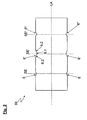
- FIG. 1 in a schematic overview representation of the inventive method for producing a winding tape 1 shown in a first process step, a material mixture, preferably a mixture of unsintered Polytetrafluoroethylene powder, a lubricant and optionally one or more dyes by means of a filling device 8 filled in a blank press 2.
- a material mixture preferably a mixture of unsintered Polytetrafluoroethylene powder, a lubricant and optionally one or more dyes
- a filling device 8 filled in a blank press 2.
- a cylindrical blank 3 is produced.
- the pressing pressure of the blank 3 is preferably controlled by means of a pressure measuring and control device 12 and kept constant for a defined time.
- the blank press 2 is opened after the pressing of the blank 3 and the cylindrical blank 3 is inserted or pressed into a carrier and support sleeve 11.
- the support and support sleeve 11 is formed for example in the form of a tube and made of a plastic material, which is formed, for example, transparent.
- the support and support sleeve 11 is realized in the form of a plexiglass tube. For clarity, this step is in the FIG. 1 not explicitly shown.
- the blank can also be stored and stored until further processing.
- the blank 3 located in the Plexiglas tube 11 is in a further step of the method according to the invention (in the FIG. 1 shown behind the double arrow) of a monofilament press 4 comprising at least one nozzle 9, preferably a spray nozzle with a predetermined outlet opening 9a supplied.
- a monofilament press 4 comprising at least one nozzle 9, preferably a spray nozzle with a predetermined outlet opening 9a supplied.
- the plexiglass tube 11 is preferably placed in a horizontal orientation on corresponding brackets on the Monofilpresse 4 and the blank 3 is pushed out, for example by means of a slide or punch from the Plexiglas tube 11 and inserted for example via a corresponding insertion cylinder on the Monofilpresse 4 and in this way the Monofil 4 fed.
- a smaller-sized monofilament strand 7 is pressed out with a predetermined cross-sectional shape. It is preferably ensured that the pressing out of the monofilament strand 7 is carried out both with a defined speed and with a defined reduction ratio.
- a monofilament strand 7 having a substantially oval cross-sectional shape or a monofilament strand 7 having a substantially polygonal, particularly preferably rectangular, cross-sectional shape is pressed out.
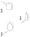
- FIGS. 3a to 3c Various possible cross-sectional shapes of the extruded monofilament strand are in the FIGS. 3a to 3c shown.
- the monofilament strand 7 is provided for this purpose by a circumferential recess 6 (in FIG. 1) provided on the peripheral surface of the at least second roller 5b FIG. 2 shown) and by means of both rigid rollers 5a, 5b so rolled to the winding tape 1 that the winding tape 1 at least partially assumes a predetermined by the recess 6 of the at least second roller 5b and the peripheral surface of the first roller 5a form.
- the cross-sectional shape of the extruded monofilament strand 7 is approximately matched to the shape of the recess 6.
- the feeding of the monofilament strand 7 in the circumferential recess 6 of the second roller 5b of the calender roll assembly 5 is preferably carried out by means of a feeding and positioning device 10, namely a guide wedge.
- a feeding and positioning device 10 Via the guide wedge 10, the monofilament strand 7 can be supplied at a precisely defined position of the recess 6 on the circumferential surface of the second roller 5b.
- the monofilament strand 7 is centered with the aid of the feeding and positioning device 10 in a corresponding circumferential recess 6 on the peripheral surface of the second roller 5b, as it is known from FIG. 2 and the associated description.
- both rollers 5a, 5b are steel rollers, wherein the first roller 5a is cylindrical and has a drive and the second roller 5b is formed as a shaping roller with circumferential recesses 6.
- the second roller 5b additionally has a plastic insert for slip control.
- the calender roll arrangement 5 of the illustrated example comprises, in addition to the first and second rolls 5a, 5b, in addition a pickup 5c and a rewinder 5d with guide roll 5e for winding up the finished winding tape 1.
- FIG. 2 is a schematic longitudinal sectional view through the forming roller 5b of FIG. 1 shown.
- the roller 5b has with its longitudinal axis LA three peripheral depressions 6, 6 ', 6 ", which are arranged and distributed along the longitudinal axis LA of the roller 5b, the circumferential recesses 6, 6 ', 6 ", which essentially have a bottom section 6.1 and a wall section 6.2, differ in cross-sectional size and shape, with all cross-sectional shapes of the three recesses 6, 6', 6" of the illustrated example having approximately the shape of a circular section ,
- a perpendicular to the longitudinal axis LA of the roller 5b and through the bottom section 6.1 of the recesses 6, 6 ', 6 "extending cutting plane SE, SE', SE” across the roller 5b represents a plane of symmetry of the recesses 6, 6 ', 6 "and an axis of symmetry with respect to the cross-sectional shape of the recesses 6, 6 ', 6 ".
- the inventive supply of the monofilament strand 7 in the recesses 6, 6', 6" of the roller 5b by means of the feeding and positioning device 10 takes place at an imaginary cutting line of Symmetry or sectional planes SE, SE ', SE "with the bottom sections 6.1 of the recesses 6, 6', 6", namely centrally into the recesses 6, 6 ', 6 ".
- the monofilament strand 7 can be centrally introduced into a correspondingly required recess 6, 6 ', 6 "of the roll 5b with the aid of the feeding and positioning device 10.
- FIGS. 3a to 3c are cross-sectional views of various embodiments of madeffesster monofilament strands 7 shown.
- the cross-sectional shape of the extruded monofilament strand 7 is approximated to the shape of the circumferential recess 6 of the at least second roller 5b, so that the rolling can be performed effectively by the rollers 5a, 5b in an optimized manner.
- the cross-sectional shape of the monofilament strand is determined by the shape of the outlet opening 9a of the nozzle 9, wherein a length I of the cross section of the monofilament strand 7 at the same time the length I of the outlet opening 9a of the nozzle 9 and a width b of the cross section of the monofilament strand 7 at the same time the width b of the outlet opening 9a of the nozzle 9 represents.
- a monofilament strand 7 is shown having a substantially oval cross-sectional shape.
- the ratio of width b to length I is preferably in a range of 1: 1.05 to 1: 5, more preferably in a range of 1: 1.1 to 1: 3, in the example shown, the ratio of width b to Length I 1: 2.
- the FIGS. 3b and 3c show examples of monofilament strands 7 with approximately rectangular cross-sectional shape, wherein the ratio of width b to length I preferably in a range of 1: 1 to 1:15, more preferably in a range of 1: 1 to 1:10, in the example shown of the FIG. 3b the ratio of width b to length I is 1: 1, in the example of Figure 3c it is 1: 5.
- FIG. 4 shows a cross section of a method according to the invention of FIG. 1
- the monofilament strand 7 is rolled out to the winding band 1 in such a way that the winding band 1 at least partially assumes a shape predetermined by the recess 6 of the at least second roller 5b and the circumferential surface of the first roller 5a.
- the winding tape 1 of the illustrated example has a substantially plano-convex cross-sectional shape with a curved and a smooth side.
- the plano-convex cross-sectional shape is determined by the predetermined by the recess 6 of the second rigid roller 5b and the peripheral surface of the rigid and cylindrical, smooth first roller 5a form.
- the wrapping tape 1 has a thicker central region 1 'and two thinner edge regions 1 "bordering it.
- the edge regions 1" increasingly flatten outwards and finally terminate in the winding tape edges 1.1.
- the thickness d in the central region 1 ' is preferably between 30 ⁇ m and 200 ⁇ m, and the thickness d in the edge region 1 "between 5 ⁇ m and 30 ⁇ m
- the winding tape edges 1.1 particularly preferably have a thickness d of less than or equal to 5 ⁇ m and preferably run with a thickness d going from 0 to ..
Landscapes
- Engineering & Computer Science (AREA)
- Mechanical Engineering (AREA)
- Physics & Mathematics (AREA)
- Spectroscopy & Molecular Physics (AREA)
- Casting Or Compression Moulding Of Plastics Or The Like (AREA)
- Treatment Of Fiber Materials (AREA)
- Spinning Methods And Devices For Manufacturing Artificial Fibers (AREA)
- Paper (AREA)
- Auxiliary Devices For And Details Of Packaging Control (AREA)
Description
- Die Erfindung betrifft ein Verfahren zur Herstellung eines Wickelbandes nach dem Oberbegriff des Anspruches 1 sowie eine zugehörige Vorrichtung nach dem Oberbegriff des Anspruches 9.
- Verfahren zur Herstellung von Wickelbändern aus sinterfähigen Kunststoffen wie beispielsweise Polytetrafluorethylen sind aus dem Stand der Technik bekannt. Derartige Wickelbänder werden vorzugsweise für die Isolierung elektrischer Kabel und Leitungen eingesetzt. Die in der Regel durch Auswalzen hergestellten Wickelbänder werden meist wendelförmig mehrlagig bzw. überlappend aufgewickelt und die Ränder des Wickelbänder werden mit den darunter liegenden Lagen beispielsweise durch nachträgliches Sintern verbunden.
- Von besonderer Bedeutung ist hierbei, dass die aus einem Wickelband hergestellte Isolierhülle nahezu spaltenfrei und kompakt ist und dass die Oberfläche glatt ist und keine Stoßkanten aufweist, welche Angriffspunkte für von außen wirkende mechanische Kräfte darstellen.
- Aus der
DE32 14 447 C2 beispielsweise ist ein ungesintertes Wickelband mit einer plankonvexen Querschnittsform bekannt, bei dem eine obere Begrenzungslinie gekrümmt und eine untere Begrenzungslinie gerade ist. Die Banddicke im mittleren Bereich des Bandes ist dabei im Vergleich zu den Rändern verstärkt. Durch überlappendes Aufwickeln des Wickelbandes, nämlich mit einer Überlappung der im Vergleich zur verstärkten Bandmitte dünneren Ränder, kann eine geschlossene, kompakte und oberflächenglatte Umhüllung erzeugt werden. - In der
DE 41 03 540 C2 und derDE 102 01 833 A1 wird jeweils ein Verfahren zur Herstellung eines Wickelbandes mit einer von der Rechteckform abweichenden Querschnittsform angegeben. So offenbart dieDE 41 03 540 C2 beispielsweise ein Verfahren, bei dem zunächst ein Bandmaterial mit mindestens der zweifachen Breite des Wickelbandes geformt und anschließend über eine Quetschtrennung getrennt wird, wodurch Wickelbänder mit einer zu den Kanten hin spitz zulaufenden Querschnittsform erzeugt werden. - Die
DE 102 01 833 A1 stellt ein Verfahren zur Verfügung, bei dem eine zunächst aus einem Rohling ausgepresste Rundschnur mit kreisrundem Querschnitt zu einem Band ausgewalzt wird. Die Rundschnur wird dabei druckbelastet in einer radialen Richtung derart ausgewalzt, dass die im mittleren Teil des Bandes verbleibende Materialmenge größer ist als die zu den Bandkanten hin verbleibende Materialmenge. Wesentlich für dieses Verfahren ist, dass bei dem Walzvorgang die Oberfläche mindestens einer Walze druckbelastet verformt wird. - Nachteilig an dem in der
DE 102 01 833 A1 angegebenen Verfahren ist zum einen, dass ausschließlich Rundschnüre mit kreisrundem Querschnitt ausgewalzt werden können, da es sonst zu Unregelmäßigkeiten in Dicke und Breite des Bandes kommen kann. Außerdem sind Gleichmäßigkeit und Qualität des Wickelbandes stark von den Materialeigenschaften der Walze, nämlich von deren Elastizität abhängig. Nimmt beispielsweise die Elastizität der Walze aufgrund Materialalterung ab, so kann dies sowohl Form als auch Qualität des Wickelbandes negativ beeinträchtigen - Aufgabe der vorliegenden Erfindung ist es daher, das aus dem Stand der Technik bekannte Verfahren zu verbessern. Die Aufgabe wird ausgehend von den Merkmalen des Oberbegriffes des Patentanspruches 1 durch dessen kennzeichnende Merkmale gelöst.
- Die vorliegende Erfindung beschreibt ein Verfahren zur Herstellung eines Wickelbandes, bei dem aus einem Materialgemisch, vorzugsweise aus einem Gemisch aus ungesintertem Polytetrafluorethylenpulver und einem Gleitmittel zunächst ein zylinderförmiger Rohling gepresst wird. In einem nächsten Schritt wird der Rohling dann zu einem geringer dimensionierten monofilen Strang mit einer vorgegebenen Querschnittsform ausgepresst. Der monofile Strang wird anschließend in einer Kalanderwalzenanordnung mit zumindest einer ersten und einer zweiten starren Walze zu einem Wickelband ausgewalzt. Der wesentliche Aspekt des erfindungsgemäßen Verfahrens ist darin zu sehen, dass der monofile Strang einer auf der Umfangsfläche der zumindest zweiten Walze vorgesehenen umlaufenden Vertiefung zugeführt wird und mittels beider starren Walzen derart zu dem Wickelband ausgewalzt wird, dass das Wickelband zumindest teilweise eine durch die Vertiefung der zumindest zweiten starren Walze und die Umfangsfläche der ersten starren Walze vorgegebene Form annimmt. Die Querschnittsform des ausgepressten monofilen Stranges wird dabei näherungsweise auf die Form der umlaufenden Vertiefung abgestimmt.
- In anderen Worten ausgedrückt wird der monofile Strang in die auf der Umfangsfläche der zumindest zweiten Walze vorgesehene umlaufende Vertiefung eingeführt. Die Vertiefung der zweiten Walze bildet zusammen mit der Umfangsfläche der ersten Walze einen Hohlraum aus, der quasi mit einer Walz- bzw. Gießform verglichen werden kann und letztlich formgebend für das Wickelband ist. Das Wickelband nimmt also zumindest teilweise die Form der durch die Vertiefung der zweiten Walze und die Umfangsfläche der ersten Walze gebildeten Form an.
- Da es sich bei den Walzen um starre Walzen handelt und das Walzenmaterial, vorzugsweise Stahl fest und widerstandsfähig ist, ist die Form der umlaufenden Vertiefung auch unter extremer Beanspruchung gleichbleibend. So ist beispielsweise aufgrund von Druckbeanspruchungen des Walzenpaares keine Veränderung der Oberfläche zu erwarten. Dadurch wird eine immer gleich bleibende Formgebung und Qualität des Wickelbandes gewährleistet. Mit dem erfindungsgemäßen Verfahren wird daher insbesondere auch bei ausgedehnter Betriebsdauer bzw. bei langem Einsatz der verwendeten Walzen ein sicherer, stabiler und dennoch einfacher Herstellungsprozess zur Verfügung gestellt.
- Besonders vorteilhaft wird die Querschnittsform des monofilen Stranges, welcher zunächst aus dem Rohling ausgepresst wird, auf die Form der Vertiefung abgestimmt, so dass beispielsweise die relative Längen- und/oder Breitenzunahme des monofilen Stranges während des Auswalzens zum Wickelband vorbestimmt werden kann und somit der Faktor für Längen- und/oder Breitenzunahme definiert bzw. reguliert werden kann.
- Besondere Vorzüge ergeben sich, wenn der auf der Umfangsfläche der zumindest zweiten Walze vorgesehenen umlaufenden Vertiefung ein monofiler Strang mit im Wesentlichen ovaler Querschnittsform oder ein monofiler Strang mit im Wesentlichen polygoner, vorzugsweise rechteckiger Querschnittsform zugeführt wird. Abhängig von der Form der umlaufenden Vertiefung der zumindest zweiten Walze, von der Art, Form und Größe des herzustellenden Wickelbandes, sowie von dem gewünschten Faktor für Längen- und/oder Breitenzunahme können monofile Stränge unterschiedlichster Querschnittsformen zugeführt werden. Neben der grundsätzlichen Querschnittsform ist ebenso die Querschnittsgröße, nämlich bezogen auf Länge und Breite wählbar. So kann bei im Wesentlichen ovalen Querschnittsformen das Verhältnis von Breite b zu Länge I des Querschnitts bevorzugt in einem Bereich von 1:1,05 bis 1:10, besonders bevorzugt in einem Bereich von 1:1,1 bis 1:3, insbesondere bevorzugt bei 1:2 liegen. Bei polygonen, näherungsweise rechteckigen Querschnittsformen kann das Verhältnis von Breite b zu Länge I bevorzugt in einem Bereich von 1:1 bis 1:15, besonders bevorzugt in einem Bereich von 1:1 bis 1:10, insbesondere bevorzugt bei 1:5 liegen.
- Der ausgepresste monofile Strang wird bevorzugt mittels einer Zuführungs- und Positionierungseinrichtung der auf der Umfangsfläche der zumindest zweiten Walze vorgesehenen umlaufenden Vertiefung zugeführt, besonders bevorzugt wird der monofile Strang zentrisch zugeführt, wobei die "zentrische Zuführung" im Sinne der vorliegenden Erfindung im Folgenden kurz erläutert wird. Jede umlaufende Vertiefung weist im Prinzip einen Bodenabschnitt und Wandabschnitte auf und kann mit einer senkrecht zur Längsachse der Walze und durch den Bodenabschnitt der Vertiefung verlaufenden Schnittebene quer zur Walze "geschnitten" werden. Diese Schnittebene stellt eine Symmetrieebene der Vertiefung bzw. eine Symmetrieachse bezüglich der Querschnittsform der Vertiefung dar. Die Zuführung des monofilen Stranges in die Vertiefungen der Walze mit Hilfe der Zuführungs- und Positionierungseinrichtung erfolgt an einer gedachten Schnittlinie dieser Symmetrie- bzw. Schnittebene mit dem Bodenabschnitt der Vertiefung, nämlich zentrisch.
- Während des ersten Verfahrensschrittes, nämlich dem Pressen eines Rohlings in einer Rohlingspresse kann der Pressdruck in der Rohlingspresse über eine Druckmess und - regelungseinrichtung bestimmt und für die Dauer eines definierten Zeitraumes auf einem vorgegebenen Wert gehalten werden. Ebenso kann der gepresste zylinderförmige Rohling nach dem Entnehmen aus der Rohlingspresse optional zunächst in eine Träger- und Stützhülse eingeschoben werden. Mittels der Träger- und Stützhülse, welche beispielsweise in Form eines Plexiglasrohres ausgebildet sein kann, kann der Rohling in besonders einfacher und handlicher Weise der Monofilpresse zugeführt werden. Außerdem stellt die Träger- und Stützhülse eine praktische und sichere Aufbewahrungs- und Lagerungsmöglichkeit für Rohlinge dar.
- In einer bevorzugten Ausführungsform der vorliegenden Erfindung wird der monofile Strang in der Monofilpresse mittels einer Düse mit vorgegebener Austrittsöffnung ausgepresst, wobei die Pressgeschwindigkeit und/oder das Reduktionsverhältnis reguliert werden. Eine derartige Auspressung mittels Düsen wird gemeinhin als Extrusion bezeichnet. Die Extrusion stellt im Wesentlichen ein kontinuierliches Verfahren dar, bei dem das zu verarbeitende Material durch eine spezielle Düse gepresst wird und dabei Körper mit dem Querschnitt der Düse in beliebiger Länge entstehen. Besonders bevorzugt wird in der vorliegenden Erfindung mittels unterschiedlich geformter Düsen bzw. Austrittsöffnungen der Düsen der monofile Strang mit vorgegebener bzw. gewünschter und näherungsweise an die Vertiefung der Walze angepasster Querschnittsform ausgepresst, wobei die Querschnittsform des ausgepressten monofilen Stranges und die Querschnittsform der Austrittsöffnung der Düse entsprechend gleich sind.
- Die vorliegende Erfindung umfasst ebenso eine Vorrichtung zur Herstellung eines Wickelbandes nach dem angegebenen Verfahren. Die Vorrichtung umfasst zumindest eine Rohlingspresse, wenigstens eine Monofilpresse mit einer Düse aufweisend eine vorgegebene Austrittsöffnung und eine Kalanderwalzenanordnung mit zumindest einer ersten und einer zweiten starren Walze, dadurch gekennzeichnet, dass wenigstens die zweite starre Walze zumindest eine umlaufende Vertiefung auf ihrer Umfangsfläche aufweist.
- Die beiden starren Walzen sind im Wesentlichen zylinderförmig und vorzugsweise aus Stahl hergestellt. Beispielsweise können die starren Walzen aus Stahl mit unterschiedlichen Härtegraden hergestellt sein. Alternativ oder zusätzlich können die Walzen eine Oberflächenbeschichtung aufweisen. Die erste Walze weist beispielsweise eine glatte Oberfläche auf, kann alternativ aber analog zur zweiten Walze, über umlaufende Vertiefungen auf ihrer Umfangsfläche verfügen. Bevorzugt ist zumindest die erste Walze mit einem geeigneten Antrieb versehen. Die zweite Walze wird entweder über die erste Walze angetrieben oder verfügt alternativ ebenso über einen eigenen Antrieb. Die Kalanderwalzenanordnung kann beispielsweise zusätzliche Walzen wie einen Abnehmer, Aufwickler und Führungsrollen umfassen.
- Die für das Verfahren zur Herstellung eines Wickelbandes geltenden Vorteile, welche unter den entsprechenden Aspekten betreffend das Verfahren bereits genannt wurden und auf die hier insbesondere verwiesen wird, beziehen sich ebenso in analoger Weise auf die Vorrichtung zur Durchführung des Verfahrens.
- Besondere Vorteile ergeben sich, wenn die Vorrichtung zusätzlich eine Zuführungs- und Positionierungseinrichtung zur Zuführung des ausgepressten monofilen Stranges in die umlaufende Vertiefung der zweiten Walze umfasst. In einer weiteren bevorzugten Ausführungsform der vorliegenden Erfindung weist die Düse der Monofilpresse eine Austrittsöffnung mit im wesentlichen ovaler Querschnittsform auf, wobei das Seitenverhältnis von Länge zu Breite der Austrittsöffnung in einem Bereich von 1,05:1 bis 2:1 liegt. Alternativ weist die Düse eine Austrittsöffnung mit im wesentlichen polygonem, vorzugsweise rechteckförmigem Querschnitt auf, wobei das Seitenverhältnis von Länge zu Breite der Austrittsöffnung in einem Bereich von 1:1 bis 10:1 liegt.
- Bevorzugt sind zwei, drei oder mehrere umlaufende Vertiefungen auf der Umfangsfläche der zumindest zweiten Walze ausgebildet, wobei die umlaufenden Vertiefungen entlang einer Längsachse der Walze verteilt angeordnet sind und jede umlaufende Vertiefung eine vorgegebene Querschnittsform aufweist. Eine durch die Vertiefung verlaufende und senkrecht zur Längsachse der Walze ausgerichtete Schnittebene stellt dabei eine Symmetrieachse bezüglich der Querschnittsform der Vertiefung dar.
- Bevorzugt weist der Querschnitt der umlaufenden Vertiefung im Wesentlichen die Form eines Kreisabschnittes bzw. Kreissegmentes auf. Je nach Kreisradius, Segmenthöhe, Mittelpunktswinkel und Länge des Kreisbogens sind die genaue Form, die Fläche und die Größe des kreissegmentförmigen Querschnittes der Vertiefungen frei wählbar und es stehen somit Vertiefungen in unterschiedlichen Formen und Größen zum Auswalzen verschieden dimensionierter Wickelbänder zur Verfügung. In alternativen Ausführungsformen kann der Querschnitt der umlaufenden Vertiefungen jedoch auch im Wesentlichen vieleckig mit beispielsweise spitz zulaufenden Ecken geformt sein.
- Die Erfindung soll nachfolgend anhand von Ausführungsbeispielen im Zusammenhang mit den Figuren näher erläutert werden. Zudem ergeben sich Weiterbildungen, Vorteile und Anwendungsmöglichkeiten der Erfindung auch aus der nachfolgenden Beschreibung der Ausführungsbeispiele und aus den Figuren. Dabei sind alle beschriebenen und/oder bildlich dargestellten Merkmale für sich oder in beliebiger Kombination grundsätzlich Gegenstand der Erfindung, unabhängig von ihrer Zusammenfassung in den Ansprüchen oder deren Rückbeziehung. Auch wird der Inhalt der Ansprüche zu einem Bestandteil der Beschreibung gemacht.
- Es wird aber ausdrücklich darauf hingewiesen, dass die Erfindung keinesfalls auf die angegebenen Beispiele beschränkt sein soll. Es zeigen
- Fig. 1
- eine schematische Übersichtsdarstellung über das erfindungsgemäße Fertigungsverfahren,
- Fig. 2
- eine schematische Schnittdarstellung durch eine Walze mit umlaufenden Vertiefungen,
- Fig. 3a
- den Querschnitt durch einen monofilen Strang,
- Fig. 3b
- den Querschnitt durch eine weitere Ausführungsform eines monofilen Stranges,
- Fig. 3c
- den Querschnitt durch eine weitere Ausführungsform eines monofilen Stranges,
- Fig. 4
- den Querschnitt eines nach dem erfindungsgemäßen Verfahren hergestellten Wickelbandes.
- Bei dem in der
Figur 1 in einer schematischen Übersichtsdarstellung gezeigten erfindungsgemäßen Verfahren zur Herstellung eines Wickelbandes 1 wird in einem ersten Verfahrensschritt ein Materialgemisch, vorzugsweise ein Gemisch aus ungesintertem Polytetrafluorethylenpulver, einem Gleitmittel und wahlweise einem oder mehrerer Farbstoffe mit Hilfe einer Einfüllvorrichtung 8 in eine Rohlingspresse 2 eingefüllt. Mittels Pressung in der Rohlingspresse 2 wird ein zylinderförmiger Rohling 3 hergestellt. Im dargestellten Beispiel wird zum Pressen des Rohlings 3 vorzugsweise der Pressdruck mittels einer Druckmess und -regelungseinrichtung 12 kontrolliert und für eine definierte Zeit konstant gehalten. - Im dargestellten Beispiel wird die Rohlingspresse 2 nach der Pressung des Rohlings 3 geöffnet und der zylinderförmige Rohling 3 wird in eine Träger- und Stützhülse 11 eingeführt bzw. eingedrückt. Die Träger- und Stützhülse 11 ist beispielsweise in Form eines Rohres ausgebildet und aus einem Kunststoffmaterial hergestellt, welches beispielsweise transparent ausgebildet ist. Vorzugsweise ist die Träger- und Stützhülse 11 in Form eines Plexiglasrohres realisiert. Aus Übersichtsgründen ist dieser Schritt in der
Figur 1 nicht explizit dargestellt. In dem Plexiglasrohr 11 kann der Rohling bis zur Weiterverarbeitung auch aufbewahrt und gelagert werden. - Der in dem Plexiglasrohr 11 befindliche Rohling 3 wird in einem weiteren Schritt des erfindungsgemäßen Verfahrens (in der
Figur 1 hinter dem Doppelpfeil gezeigt) einer Monofilpresse 4 umfassend zumindest eine Düse 9, vorzugsweise eine Spritzdüse mit einer vorgegebenen Austrittsöffnung 9a, zugeführt. Dazu wird das Plexiglasrohr 11 vorzugsweise in horizontaler Ausrichtung auf entsprechende Halterungen an der Monofilpresse 4 aufgelegt und der Rohling 3 wird beispielsweise mittels eines Schiebers oder Stempels aus dem Plexiglasrohr 11 herausgedrückt und zum Beispiel über einen entsprechenden Einführzylinder an der Monofilpresse 4 eingeschoben und auf diese Weise der Monofilpresse 4 zugeführt. Mittels der Düse 9 wird ein geringer dimensionierter monofiler Strang 7 mit einer vorgegebenen Querschnittsform ausgepresst. Vorzugsweise wird darauf geachtet, dass das Auspressen des monofilen Stranges 7 sowohl mit einer definierten Geschwindigkeit als auch mit einem definierten Reduktionsverhältnis durchgeführt wird. In bevorzugten Ausführungsformen wird ein monofiler Strang 7 mit im Wesentlichen ovaler Querschnittsform oder ein monofiler Strang 7 mit im Wesentlichen polygoner, besonders bevorzugt rechteckiger Querschnittsform ausgepresst. Verschiedene mögliche Querschnittsformen des ausgepressten monofilen Stranges sind in denFiguren 3a bis 3c dargestellt. - In einem letzten Schritt des Verfahrens wird der monofile Strang 7 mit vorgegebener Querschnittsform in einer Kalanderwalzenanordnung 5 mit zumindest einer ersten und einer zweiten starren, jeweils eine Längsachse LA aufweisenden Walze 5a, 5b zu dem Wickelband 1 ausgewalzt. Erfindungsgemäß wird der monofile Strang 7 dazu einer auf der Umfangsfläche der zumindest zweiten Walze 5b vorgesehenen umlaufenden Vertiefung 6 (in der
Figur 2 dargestellt) zugeführt und mittels beider starrer Walzen 5a, 5b derart zu dem Wickelband 1 ausgewalzt, dass das Wickelband 1 zumindest teilweise eine durch die Vertiefung 6 der zumindest zweiten Walze 5b und die Umfangsfläche der ersten Walze 5a vorgegebene Form annimmt. Die Querschnittsform des ausgepressten monofilen Stranges 7 wird dabei näherungsweise auf die Form der Vertiefung 6 abgestimmt. - Die Zuführung des monofilen Stranges 7 in die umlaufende Vertiefung 6 der zweiten Walze 5b der Kalanderwalzenanordnung 5 erfolgt bevorzugt mittels einer Zuführungs- und Positionierungseinrichtung 10, nämlich einem Führungskeil. Über den Führungskeil 10 kann der monofile Strang 7 an einer exakt definierten Position der Vertiefung 6 auf der Umfangsfläche der zweiten Walze 5b zugeführt werden. Insbesondere wird der monofile Strang 7 mit Hilfe der Zuführungs- und Positionierungseinrichtung 10 zentrisch in eine entsprechende umlaufende Vertiefung 6 auf der Umfangsfläche der zweiten Walze 5b eingeführt, wie es aus der
Figur 2 und der dazugehörigen Beschreibung näher hervorgeht. - Im dargestellten Ausführungsbeispiel handelt es sich bei beiden Walzen 5a, 5b um Stahlwalzen, wobei die erste Walze 5a zylindrisch ist und über einen Antrieb verfügt und die zweite Walze 5b als formgebende Walze mit umlaufenden Vertiefungen 6 ausgebildet ist. Vorzugsweise weist die zweite Walze 5b zusätzlich einen Kunststoffeinsatz zur Schlupfregelung auf. Die Kalanderwalzenanordnung 5 des dargestellten Beispieles umfasst neben der ersten und zweiten Walze 5a, 5b zusätzlich einen Abnehmer 5c und einen Aufwickler 5d mit Führungsrolle 5e zum Aufwickeln des fertig gestellten Wickelbandes 1.
- In der
Figur 2 ist eine schematische Längsschnittdarstellung durch die formgebende Walze 5b derFigur 1 gezeigt. Im dargestellten Beispiel weist die Walze 5b mit einer Längsachse LA auf ihrer Umfangsfläche drei umlaufende Vertiefungen 6, 6', 6" auf, welche entlang der Längsachse LA der Walze 5b angeordnet und verteilt sind. Die umlaufenden Vertiefungen 6, 6', 6", welche im Wesentlichen einen Bodenabschnitt 6.1 und einen Wandabschnitt 6.2 aufweisen, unterscheiden sich in Querschnittsgröße und -form, wobei alle Querschnittsformen der drei Vertiefungen 6, 6', 6" des dargestellten Beispieles näherungsweise die Form eines Kreisabschnittes aufweisen. - Eine senkrecht zur Längsachse LA der Walze 5b und durch den Bodenabschnitt 6.1 der Vertiefungen 6, 6', 6" verlaufende Schnittebene SE, SE', SE" quer durch die Walze 5b stellt eine Symmetrieebene der Vertiefungen 6, 6', 6" bzw. eine Symmetrieachse bezüglich der Querschnittsform der Vertiefungen 6, 6', 6" dar. Die erfindungsgemäße Zuführung des monofilen Stranges 7 in die Vertiefungen 6, 6', 6" der Walze 5b mit Hilfe der Zuführungs- und Positionierungseinrichtung 10 erfolgt an einer gedachten Schnittlinie der Symmetrie- bzw. Schnittebenen SE, SE', SE" mit den Bodenabschnitten 6.1 der Vertiefungen 6, 6', 6", nämlich zentrisch in die Vertiefungen 6, 6', 6".
- Je nach Bedarf, nämlich je nach Art des herzustellenden Wickelbandes 1 kann der monofile Strang 7 mit Hilfe der Zuführungs- und Positionierungseinrichtung 10 zentrisch in eine entsprechend benötigte Vertiefung 6, 6', 6" der Walze 5b eingeführt werden. So kann beispielsweise für dünne, schmale Wickelbänder 1 die umlaufende Vertiefung 6 die zur Formgebung korrekte Vertiefung sein, wohin gegen die umlaufende Vertiefung 6' vornehmlich zur Herstellung breiterer, dickerer Wickelbänder 1 benutzt wird.
- In den
Figuren 3a bis 3c sind Querschnittsdarstellungen verschiedener Ausführungsformen ausgepresster monofiler Stränge 7 gezeigt. Gemäß der vorliegenden Erfindung wird die Querschnittsform des ausgepressten monofilen Stranges 7 näherungsweise auf die Form der umlaufenden Vertiefung 6 der zumindest zweiten Walze 5b abgestimmt, so dass das Auswalzen mittels der Walzen 5a, 5b in einer optimierten Weise effektiv durchgeführt werden kann. Die Querschnittsform des monofilen Stranges wird durch die Form der Austrittsöffnung 9a der Düse 9 bestimmt, wobei eine Länge I des Querschnittes des monofilen Stranges 7 gleichzeitig die Länge I der Austrittsöffnung 9a der Düse 9 und eine Breite b des Querschnittes des monofilen Stranges 7 gleichzeitig die Breite b der Austrittsöffnung 9a der Düse 9 darstellt. - In der
Figur 3a ist ein monofiler Strang 7 mit im Wesentlichen ovaler Querschnittsform gezeigt. Das Verhältnis von Breite b zu Länge I liegt bevorzugt in einem Bereich von 1:1,05 bis 1:5, besonders bevorzugt in einem Bereich von 1:1,1 bis 1:3, im dargestellten Beispiel beträgt das Verhältnis von Breite b zu Länge I 1:2. DieFiguren 3b und 3c zeigen Beispiele von monofilen Strängen 7 mit näherungsweise rechteckiger Querschnittsform, wobei das Verhältnis von Breite b zu Länge I bevorzugt in einem Bereich von 1:1 bis 1:15, besonders bevorzugt in einem Bereich von 1:1 bis 1:10, im dargestellten Beispiel derFigur 3b beträgt das Verhältnis von Breite b zu Länge I 1:1, im Beispiel derFigur 3c beträgt es 1:5. - Die
Figur 4 zeigt einen Querschnitt eines nach dem erfindungsgemäßen Verfahren derFigur 1 hergestellten Wickelbandes 1. Mittels der starren Walzen 5a, 5b wird der monofile Strang 7 derart zu dem Wickelband 1 ausgewalzt, dass das Wickelband 1 zumindest teilweise eine durch die Vertiefung 6 der zumindest zweiten Walze 5b und die Umfangsfläche der ersten Walze 5a vorgegebene Form annimmt. Das Wickelband 1 des dargestellten Beispieles weist eine im Wesentlichen plankonvexe Querschnittsform mit einer gekrümmten und einer glatten Seite auf. Die plankonvexe Querschnittsform wird bedingt durch die durch die Vertiefung 6 der zweiten starren Walze 5b und die Umfangsfläche der starren und zylinderförmig, glatten ersten Walze 5a vorgegebene Form. - Das Wickelband 1 weist einen dickeren mittleren Bereich 1' und zwei diesen eingrenzende dünnere Randbereiche 1" auf. Die Randbereiche 1" flachen nach außen hin zunehmend ab und enden schließlich in den Wickelbandrändern 1.1. Bevorzugt beträgt die Dicke d im mittleren Bereich 1' zwischen 30 µm und 200 µm und die Dicke d im Randbereich 1" zwischen 5 µm und 30 µm. Die Wickelbandränder 1.1 weisen besonders bevorzugt eine Dicke d von kleiner oder gleich 5 µm auf und laufen vorzugsweise mit einer gegen 0 gehenden Dicke d aus..
- Die Erfindung wurde voranstehend an einem Ausführungsbeispiel beschrieben. Es versteht sich, dass zahlreiche Modifikationen und Änderungen der Erfindung möglich sind, ohne dass hierdurch der Erfindungsgedanke verlassen wird.
-
- 1
- Wickelband
- 1'
- mittlerer Bereich
- 1"
- Randbereich
- 1.1
- Wickelbandrand
- 2
- Rohlingspresse
- 3
- Rohling
- 4
- Monofilpresse
- 5
- Kalanderwalzenanordnung
- 5a, 5b
- erste und zweite Walze
- 5c
- Abnehmer
- 5d
- Aufwickler
- 5e
- Führungsrolle
- 6, 6', 6"
- umlaufende Vertiefung
- 6.1
- Bodenabschnitt
- 6.2
- Wandabschnitt
- 7
- monofiler Strang
- 8
- Einfüllvorrichtung
- 9
- Düse
- 9a
- Austrittsöffnung
- 10
- Zuführungs- und Positionierungseinrichtung
- 11
- Träger- und Stützhülse
- 12
- Druckmess und -regelungseinrichtung
- b
- Breite
- d
- Dicke
- I
- Länge
- LA
- Längsachse
- SE, SE', SE"
- Schnittebenen
Claims (15)
- Verfahren zur Herstellung eines Wickelbandes (1), bei dem aus einem Materialgemisch, vorzugsweise aus einem Gemisch aus ungesintertem Polytetrafluorethylenpulver und einem Gleitmittel zunächst ein zylinderförmiger Rohling (3) gepresst wird, der Rohling (3) dann zu einem geringer dimensionierten monofilen Strang (7) mit vorgegebener Querschnittsform ausgepresst wird und der monofile Strang (7) anschließend in einer Kalanderwalzenanordnung (5) mit zumindest einer ersten und einer zweiten starren Walze (5a, 5b) zu einem Wickelband (1) ausgewalzt wird, dadurch gekennzeichnet, dass der monofile Strang (7) einer auf der Umfangsfläche der zumindest zweiten Walze (5b) vorgesehenen umlaufenden Vertiefung (6) zugeführt wird und mittels beider Walzen (5a, 5b) derart zu dem Wickelband (1) ausgewalzt wird, dass das Wickelband zumindest teilweise eine durch die Vertiefung (6) der zumindest zweiten starren Walze (5b) und die Umfangsfläche der ersten starren Walze (5a) vorgegebene Form annimmt, wobei die Querschnittsform des ausgepressten monofilen Stranges (7) näherungsweise auf die Form der umlaufenden Vertiefung (6) abgestimmt wird.
- Verfahren nach Anspruch 1, dadurch gekennzeichnet, dass der auf der Umfangsfläche der zumindest zweiten Walze (5b) vorgesehenen umlaufenden Vertiefung (6) ein monofiler Strang (7) mit im Wesentlichen ovaler Querschnittsform zugeführt wird.
- Verfahren nach Anspruch 1, dadurch gekennzeichnet, dass der auf der Umfangsfläche der zumindest zweiten Walze (5b) vorgesehenen umlaufenden Vertiefung (6) ein monofiler Strang (7) mit im Wesentlichen polygoner, vorzugsweise rechteckiger Querschnittsform zugeführt wird.
- Verfahren nach einem der Ansprüche 1 bis 3, dadurch gekennzeichnet, dass der ausgepresste monofile Strang (7) mittels einer Zuführungs- und Positionierungseinrichtung (10) der auf der Umfangsfläche der zumindest zweiten Walze (5b) vorgesehenen umlaufenden Vertiefung (6) zugeführt wird.
- Verfahren nach Anspruch 4, dadurch gekennzeichnet, dass der ausgepresste monofile Strang (7) mittels der Zuführungs- und Positionierungseinrichtung (10) zentrisch in der umlaufenden Vertiefung (6) positioniert wird.
- Verfahren nach einem der vorhergehenden Ansprüche, dadurch gekennzeichnet, dass über eine Druckmess und -regelungseinrichtung der Pressdruck in der Rohlingspresse bestimmt wird und für die Dauer eines definierten Zeitraumes auf einem vorgegebenen Wert gehalten wird.
- Verfahren nach einem der vorhergehenden Ansprüche, dadurch gekennzeichnet, dass der gepresste zylinderförmige Rohling (3) aus der Rohlingspresse (2) entnommen und zunächst in eine Träger- und Stützhülse (11) eingeschoben wird.
- Verfahren nach einem der vorhergehenden Ansprüche, dadurch gekennzeichnet, dass der monofile Strang (7) in der Monofilpresse (4) mittels einer Düse (9) mit vorgegebener Austrittsöffnung (9a) ausgepresst wird, wobei die Pressgeschwindigkeit und/oder das Reduktionsverhältnis reguliert werden.
- Vorrichtung zur Herstellung eines Wickelbandes (1) nach dem Verfahren gemäß den Ansprüchen 1 bis 8 umfassend zumindest eine Rohlingspresse (2), wenigstens eine Monofilpresse (4) mit einer Düse (9) aufweisend eine vorgegebene Austrittsöffnung (9a) und eine Kalanderwalzenanordnung (5) mit zumindest einer ersten und einer zweiten starren Walze (5a, 5b), dadurch gekennzeichnet, dass wenigstens die zweite starre Walze (5b) zumindest eine umlaufende Vertiefung (6) auf ihrer Umfangsfläche aufweist.
- Vorrichtung nach Anspruch 9, zusätzlich umfassend eine Zuführungs- und Positionierungseinrichtung (10) zur Zuführung des ausgepressten monofilen Stranges (7) in die umlaufende Vertiefung (6) der zweiten Walze (5b) der Kalanderwalzenanordnung (5).
- Vorrichtung nach Anspruch 9 oder 10, dadurch gekennzeichnet, dass die Düse (9) der Monofilpresse (4) eine Austrittsöffnung (9a) mit im wesentlichen ovaler Querschnittsform aufweist, wobei das Seitenverhältnis von Länge (I) zu Breite (b) der Austrittsöffnung (9a) in einem Bereich von 1,1:1 bis 2:1 liegt.
- Vorrichtung nach Anspruch 9 oder 10, dadurch gekennzeichnet, dass die Düse (9) eine Austrittsöffnung (9a) mit im wesentlichen polygonem, vorzugsweise rechteckförmigem Querschnitt aufweist, wobei das Seitenverhältnis von Länge (I) zu Breite (b) der Austrittsöffnung (9a) in einem Bereich von 1:1 bis 10:1 liegt..
- Vorrichtung nach einem der Ansprüche 9 bis 12, dadurch gekennzeichnet, dass zwei, drei oder mehrere umlaufende Vertiefungen (6, 6', 6") auf der Umfangsfläche der zweiten Walze (5b) ausgebildet sind, wobei die umlaufenden Vertiefungen (6, 6', 6") entlang einer Längsachse (LA) der Walze (5b) verteilt angeordnet sind.
- Vorrichtung nach einem der Ansprüche 9 bis 13, dadurch gekennzeichnet, dass jede umlaufende Vertiefung (6, 6', 6") eine vorgegebene Querschnittsform aufweist, wobei eine durch die Vertiefung (6) verlaufende und senkrecht zur Längsachse der Walze (5b) ausgerichtete Schnittebene (SE, SE', SE") eine Symmetrieachse bezüglich der Querschnittsform der Vertiefung (6) darstellt.
- Vorrichtung nach Anspruche 14, dadurch gekennzeichnet, dass der Querschnitt der umlaufenden Vertiefung (6, 6', 6") im Wesentlichen die Form eines Kreisabschnittes aufweist.
Priority Applications (3)
| Application Number | Priority Date | Filing Date | Title |
|---|---|---|---|
| SI201230672A SI2591908T1 (sl) | 2011-11-11 | 2012-11-06 | Postopek in naprava za proizvodnjo ovojnega traku |
| RS20160617A RS55081B1 (sr) | 2011-11-11 | 2012-11-06 | Postupak i uređaj za proizvodnju trake za umotavanje |
| HRP20160977TT HRP20160977T1 (hr) | 2011-11-11 | 2016-08-01 | Postupak i uređaj za proizvodnju trake za umotavanje |
Applications Claiming Priority (1)
| Application Number | Priority Date | Filing Date | Title |
|---|---|---|---|
| DE201110055262 DE102011055262A1 (de) | 2011-11-11 | 2011-11-11 | Verfahren und Vorrichtung zur Herstellung eines Wickelbandes |
Publications (2)
| Publication Number | Publication Date |
|---|---|
| EP2591908A1 EP2591908A1 (de) | 2013-05-15 |
| EP2591908B1 true EP2591908B1 (de) | 2016-07-27 |
Family
ID=47146228
Family Applications (1)
| Application Number | Title | Priority Date | Filing Date |
|---|---|---|---|
| EP12191368.5A Active EP2591908B1 (de) | 2011-11-11 | 2012-11-06 | Verfahren und Vorrichtung zur Herstellung eines Wickelbandes |
Country Status (10)
| Country | Link |
|---|---|
| EP (1) | EP2591908B1 (de) |
| DE (1) | DE102011055262A1 (de) |
| DK (1) | DK2591908T3 (de) |
| ES (1) | ES2585813T3 (de) |
| HR (1) | HRP20160977T1 (de) |
| HU (1) | HUE030511T2 (de) |
| PL (1) | PL2591908T3 (de) |
| PT (1) | PT2591908T (de) |
| RS (1) | RS55081B1 (de) |
| SI (1) | SI2591908T1 (de) |
Family Cites Families (4)
| Publication number | Priority date | Publication date | Assignee | Title |
|---|---|---|---|---|
| CH562098A5 (de) * | 1973-02-27 | 1975-05-30 | Steiger Engineering Ag | |
| DE3214447C2 (de) * | 1982-04-20 | 1994-05-11 | Eilentropp Hew Kabel | Ungesintertes Wickelband des Polytetrafluorethylen |
| DE4103540C2 (de) * | 1991-02-06 | 1995-03-09 | Eilentropp Hew Kabel | Verfahren und Vorrichtung zur Herstellung eines Wickelbandes aus sinterfähigen Kunststoffen |
| DE10201833B4 (de) * | 2002-01-18 | 2012-06-21 | Hew-Kabel Gmbh | Verfahren zur Herstellung eines Wickelbandes aus ungesintertem Polytetrafluorethylen |
-
2011
- 2011-11-11 DE DE201110055262 patent/DE102011055262A1/de not_active Ceased
-
2012
- 2012-11-06 HU HUE12191368A patent/HUE030511T2/en unknown
- 2012-11-06 RS RS20160617A patent/RS55081B1/sr unknown
- 2012-11-06 SI SI201230672A patent/SI2591908T1/sl unknown
- 2012-11-06 ES ES12191368.5T patent/ES2585813T3/es active Active
- 2012-11-06 PL PL12191368.5T patent/PL2591908T3/pl unknown
- 2012-11-06 EP EP12191368.5A patent/EP2591908B1/de active Active
- 2012-11-06 PT PT121913685T patent/PT2591908T/pt unknown
- 2012-11-06 DK DK12191368.5T patent/DK2591908T3/en active
-
2016
- 2016-08-01 HR HRP20160977TT patent/HRP20160977T1/hr unknown
Also Published As
| Publication number | Publication date |
|---|---|
| PT2591908T (pt) | 2016-08-12 |
| RS55081B1 (sr) | 2016-12-30 |
| PL2591908T3 (pl) | 2016-11-30 |
| ES2585813T3 (es) | 2016-10-10 |
| DE102011055262A1 (de) | 2013-05-16 |
| EP2591908A1 (de) | 2013-05-15 |
| HRP20160977T1 (hr) | 2016-10-21 |
| HUE030511T2 (en) | 2017-05-29 |
| SI2591908T1 (sl) | 2016-10-28 |
| DK2591908T3 (en) | 2016-08-22 |
Similar Documents
| Publication | Publication Date | Title |
|---|---|---|
| EP1329910B1 (de) | Verfahren zur Herstellung eines Wickelbandes aus ungesintertem Polytetrafluorethylen | |
| DE2359367B2 (de) | Verfahren zur Herstellung von Verstärkungsfasern für ein vergießbares Material | |
| DE19716292A1 (de) | Strangpreßvorrichtung | |
| EP3331683A1 (de) | Giessvorrichtung zum auftragen eines aufschäumenden reaktionsgemisches | |
| AT515408A4 (de) | Diffusionsoptimiertes Mundstückbelagpapier | |
| DE102008057463A1 (de) | Feder aus einem Faserverbundwerkstoff sowie Verfahren und Vorrichtung zur Herstellung derselben | |
| DE3322194A1 (de) | Verfahren zur herstellung flexibler rohrkoerper, vorrichtung zur durchfuehrung dieses verfahrens und nach dem verfahren hergestellte rohrkoerper | |
| DD296871A5 (de) | Verfahren und vorrichtung zum herstellen eines profilierten gleitlagerelementes | |
| DE1629811B2 (de) | Vorrichtung zum herstellen von mit einlagen verstaerkten straengen unrunden querschnitts aus aushaertbaren kunststoffen | |
| DE2932964C2 (de) | ||
| EP2591908B1 (de) | Verfahren und Vorrichtung zur Herstellung eines Wickelbandes | |
| EP3541561A1 (de) | Verfahren zur herstellung eines verbundwerkstoffes durch plattieren, sowie verbundwerkstoff | |
| DE2621465C3 (de) | Verfahren zum Extrudieren eines aus Abschnitten unterschiedlicher Wanddicke bestehenden Kunstharzstrangs | |
| DE3103608C2 (de) | Verfahren zur Herstellung von Draht aus Metall | |
| WO2025040412A1 (de) | Crimpwalze, crimpwalzenpaar, crimpvorrichtung und maschine der tabak verarbeitenden industrie sowie verfahren zum crimpen einer flachbahn und herstellen eines strangs, stabförmige artikel | |
| DE2712536A1 (de) | Verfahren und vorrichtung zur herstellung eines zusammenhaengenden gegenstandes mittels extrusion eines laenglichen werkstuecks durch eine matrize | |
| EP3124661A1 (de) | Dynamisches aufspreizen von endlosfaserbündeln während eines herstellungsprozesses | |
| EP3837063B1 (de) | Dosenverpackung, sowie vorrichtung und verfahren zur herstellung dessen rohlings | |
| EP2991786B1 (de) | Verfahren zur herstellung eines drahtformkörpers aus einem drahtgewebe sowie drahtformkörper | |
| DE917723C (de) | Verfahren und Einrichtung zum kontinuierlichen Herstellen von endlosen, nahtlosen, biegsamen Rohren | |
| DE2000409A1 (de) | Verfahren und Vorrichtung zur Herstellung von Naegeln mit flachen runden Koepfen | |
| DE4103540C2 (de) | Verfahren und Vorrichtung zur Herstellung eines Wickelbandes aus sinterfähigen Kunststoffen | |
| EP3085235A1 (de) | Vorrichtung und verfahren zur herstellung von gewickelten teigprodukten aus teigstücken | |
| DE1504717B2 (de) | Vorrichtung zur herstellung von sich verjuengenden kunststoffprofilen | |
| DE4027583C2 (de) | Vorrichtung zum Pressen von Strangteilen |
Legal Events
| Date | Code | Title | Description |
|---|---|---|---|
| PUAI | Public reference made under article 153(3) epc to a published international application that has entered the european phase |
Free format text: ORIGINAL CODE: 0009012 |
|
| AK | Designated contracting states |
Kind code of ref document: A1 Designated state(s): AL AT BE BG CH CY CZ DE DK EE ES FI FR GB GR HR HU IE IS IT LI LT LU LV MC MK MT NL NO PL PT RO RS SE SI SK SM TR |
|
| AX | Request for extension of the european patent |
Extension state: BA ME |
|
| 17P | Request for examination filed |
Effective date: 20131107 |
|
| RBV | Designated contracting states (corrected) |
Designated state(s): AL AT BE BG CH CY CZ DE DK EE ES FI FR GB GR HR HU IE IS IT LI LT LU LV MC MK MT NL NO PL PT RO RS SE SI SK SM TR |
|
| 17Q | First examination report despatched |
Effective date: 20141024 |
|
| GRAP | Despatch of communication of intention to grant a patent |
Free format text: ORIGINAL CODE: EPIDOSNIGR1 |
|
| RIC1 | Information provided on ipc code assigned before grant |
Ipc: B29C 43/00 20060101ALN20160225BHEP Ipc: B29C 55/18 20060101AFI20160225BHEP Ipc: H01B 3/44 20060101ALI20160225BHEP |
|
| INTG | Intention to grant announced |
Effective date: 20160316 |
|
| GRAS | Grant fee paid |
Free format text: ORIGINAL CODE: EPIDOSNIGR3 |
|
| GRAA | (expected) grant |
Free format text: ORIGINAL CODE: 0009210 |
|
| AK | Designated contracting states |
Kind code of ref document: B1 Designated state(s): AL AT BE BG CH CY CZ DE DK EE ES FI FR GB GR HR HU IE IS IT LI LT LU LV MC MK MT NL NO PL PT RO RS SE SI SK SM TR |
|
| REG | Reference to a national code |
Ref country code: GB Ref legal event code: FG4D Free format text: NOT ENGLISH |
|
| REG | Reference to a national code |
Ref country code: CH Ref legal event code: EP |
|
| REG | Reference to a national code |
Ref country code: HR Ref legal event code: TUEP Ref document number: P20160977 Country of ref document: HR |
|
| REG | Reference to a national code |
Ref country code: RO Ref legal event code: EPE |
|
| REG | Reference to a national code |
Ref country code: PT Ref legal event code: SC4A Ref document number: 2591908 Country of ref document: PT Date of ref document: 20160812 Kind code of ref document: T Free format text: AVAILABILITY OF NATIONAL TRANSLATION Effective date: 20160803 |
|
| REG | Reference to a national code |
Ref country code: CH Ref legal event code: NV Representative=s name: MICHELI AND CIE SA, CH Ref country code: AT Ref legal event code: REF Ref document number: 815422 Country of ref document: AT Kind code of ref document: T Effective date: 20160815 |
|
| REG | Reference to a national code |
Ref country code: DK Ref legal event code: T3 Effective date: 20160818 |
|
| REG | Reference to a national code |
Ref country code: IE Ref legal event code: FG4D Free format text: LANGUAGE OF EP DOCUMENT: GERMAN Ref country code: NL Ref legal event code: FP |
|
| REG | Reference to a national code |
Ref country code: SE Ref legal event code: TRGR |
|
| REG | Reference to a national code |
Ref country code: DE Ref legal event code: R096 Ref document number: 502012007766 Country of ref document: DE |
|
| REG | Reference to a national code |
Ref country code: NO Ref legal event code: T2 Effective date: 20160727 Ref country code: ES Ref legal event code: FG2A Ref document number: 2585813 Country of ref document: ES Kind code of ref document: T3 Effective date: 20161010 |
|
| REG | Reference to a national code |
Ref country code: HR Ref legal event code: T1PR Ref document number: P20160977 Country of ref document: HR |
|
| REG | Reference to a national code |
Ref country code: FR Ref legal event code: PLFP Year of fee payment: 5 |
|
| REG | Reference to a national code |
Ref country code: LT Ref legal event code: MG4D |
|
| PG25 | Lapsed in a contracting state [announced via postgrant information from national office to epo] |
Ref country code: IS Free format text: LAPSE BECAUSE OF FAILURE TO SUBMIT A TRANSLATION OF THE DESCRIPTION OR TO PAY THE FEE WITHIN THE PRESCRIBED TIME-LIMIT Effective date: 20161127 Ref country code: LT Free format text: LAPSE BECAUSE OF FAILURE TO SUBMIT A TRANSLATION OF THE DESCRIPTION OR TO PAY THE FEE WITHIN THE PRESCRIBED TIME-LIMIT Effective date: 20160727 |
|
| PG25 | Lapsed in a contracting state [announced via postgrant information from national office to epo] |
Ref country code: GR Free format text: LAPSE BECAUSE OF FAILURE TO SUBMIT A TRANSLATION OF THE DESCRIPTION OR TO PAY THE FEE WITHIN THE PRESCRIBED TIME-LIMIT Effective date: 20161028 Ref country code: LV Free format text: LAPSE BECAUSE OF FAILURE TO SUBMIT A TRANSLATION OF THE DESCRIPTION OR TO PAY THE FEE WITHIN THE PRESCRIBED TIME-LIMIT Effective date: 20160727 |
|
| PG25 | Lapsed in a contracting state [announced via postgrant information from national office to epo] |
Ref country code: EE Free format text: LAPSE BECAUSE OF FAILURE TO SUBMIT A TRANSLATION OF THE DESCRIPTION OR TO PAY THE FEE WITHIN THE PRESCRIBED TIME-LIMIT Effective date: 20160727 |
|
| REG | Reference to a national code |
Ref country code: DE Ref legal event code: R097 Ref document number: 502012007766 Country of ref document: DE |
|
| REG | Reference to a national code |
Ref country code: HU Ref legal event code: AG4A Ref document number: E030511 Country of ref document: HU |
|
| PG25 | Lapsed in a contracting state [announced via postgrant information from national office to epo] |
Ref country code: SM Free format text: LAPSE BECAUSE OF FAILURE TO SUBMIT A TRANSLATION OF THE DESCRIPTION OR TO PAY THE FEE WITHIN THE PRESCRIBED TIME-LIMIT Effective date: 20160727 Ref country code: BG Free format text: LAPSE BECAUSE OF FAILURE TO SUBMIT A TRANSLATION OF THE DESCRIPTION OR TO PAY THE FEE WITHIN THE PRESCRIBED TIME-LIMIT Effective date: 20161027 |
|
| PLBE | No opposition filed within time limit |
Free format text: ORIGINAL CODE: 0009261 |
|
| STAA | Information on the status of an ep patent application or granted ep patent |
Free format text: STATUS: NO OPPOSITION FILED WITHIN TIME LIMIT |
|
| 26N | No opposition filed |
Effective date: 20170502 |
|
| REG | Reference to a national code |
Ref country code: HR Ref legal event code: ODRP Ref document number: P20160977 Country of ref document: HR Payment date: 20171020 Year of fee payment: 6 |
|
| REG | Reference to a national code |
Ref country code: FR Ref legal event code: PLFP Year of fee payment: 6 |
|
| PGFP | Annual fee paid to national office [announced via postgrant information from national office to epo] |
Ref country code: LU Payment date: 20171120 Year of fee payment: 6 |
|
| PGFP | Annual fee paid to national office [announced via postgrant information from national office to epo] |
Ref country code: HU Payment date: 20171115 Year of fee payment: 6 Ref country code: RO Payment date: 20171031 Year of fee payment: 6 Ref country code: DK Payment date: 20171122 Year of fee payment: 6 Ref country code: NL Payment date: 20171120 Year of fee payment: 6 Ref country code: SK Payment date: 20171103 Year of fee payment: 6 |
|
| PGFP | Annual fee paid to national office [announced via postgrant information from national office to epo] |
Ref country code: IE Payment date: 20171121 Year of fee payment: 6 Ref country code: HR Payment date: 20171020 Year of fee payment: 6 Ref country code: AT Payment date: 20171121 Year of fee payment: 6 Ref country code: PT Payment date: 20171103 Year of fee payment: 6 Ref country code: PL Payment date: 20171019 Year of fee payment: 6 Ref country code: SI Payment date: 20171025 Year of fee payment: 6 Ref country code: BE Payment date: 20171120 Year of fee payment: 6 Ref country code: RS Payment date: 20171024 Year of fee payment: 6 |
|
| PG25 | Lapsed in a contracting state [announced via postgrant information from national office to epo] |
Ref country code: CY Free format text: LAPSE BECAUSE OF FAILURE TO SUBMIT A TRANSLATION OF THE DESCRIPTION OR TO PAY THE FEE WITHIN THE PRESCRIBED TIME-LIMIT Effective date: 20160727 |
|
| PG25 | Lapsed in a contracting state [announced via postgrant information from national office to epo] |
Ref country code: MK Free format text: LAPSE BECAUSE OF FAILURE TO SUBMIT A TRANSLATION OF THE DESCRIPTION OR TO PAY THE FEE WITHIN THE PRESCRIBED TIME-LIMIT Effective date: 20160727 Ref country code: MC Free format text: LAPSE BECAUSE OF FAILURE TO SUBMIT A TRANSLATION OF THE DESCRIPTION OR TO PAY THE FEE WITHIN THE PRESCRIBED TIME-LIMIT Effective date: 20160727 |
|
| PGFP | Annual fee paid to national office [announced via postgrant information from national office to epo] |
Ref country code: MT Payment date: 20171023 Year of fee payment: 6 |
|
| PG25 | Lapsed in a contracting state [announced via postgrant information from national office to epo] |
Ref country code: AL Free format text: LAPSE BECAUSE OF FAILURE TO SUBMIT A TRANSLATION OF THE DESCRIPTION OR TO PAY THE FEE WITHIN THE PRESCRIBED TIME-LIMIT Effective date: 20160727 |
|
| REG | Reference to a national code |
Ref country code: HR Ref legal event code: PBON Ref document number: P20160977 Country of ref document: HR Effective date: 20181106 |
|
| REG | Reference to a national code |
Ref country code: DK Ref legal event code: EBP Effective date: 20181130 |
|
| REG | Reference to a national code |
Ref country code: NL Ref legal event code: MM Effective date: 20181201 |
|
| REG | Reference to a national code |
Ref country code: AT Ref legal event code: MM01 Ref document number: 815422 Country of ref document: AT Kind code of ref document: T Effective date: 20181106 |
|
| PG25 | Lapsed in a contracting state [announced via postgrant information from national office to epo] |
Ref country code: PT Free format text: LAPSE BECAUSE OF NON-PAYMENT OF DUE FEES Effective date: 20190506 Ref country code: LU Free format text: LAPSE BECAUSE OF NON-PAYMENT OF DUE FEES Effective date: 20181106 |
|
| REG | Reference to a national code |
Ref country code: SK Ref legal event code: MM4A Ref document number: E 21750 Country of ref document: SK Effective date: 20181106 |
|
| REG | Reference to a national code |
Ref country code: BE Ref legal event code: MM Effective date: 20181130 |
|
| REG | Reference to a national code |
Ref country code: IE Ref legal event code: MM4A |
|
| PG25 | Lapsed in a contracting state [announced via postgrant information from national office to epo] |
Ref country code: SI Free format text: LAPSE BECAUSE OF NON-PAYMENT OF DUE FEES Effective date: 20181107 Ref country code: RS Free format text: LAPSE BECAUSE OF NON-PAYMENT OF DUE FEES Effective date: 20190513 Ref country code: HR Free format text: LAPSE BECAUSE OF NON-PAYMENT OF DUE FEES Effective date: 20181106 Ref country code: NL Free format text: LAPSE BECAUSE OF NON-PAYMENT OF DUE FEES Effective date: 20181201 Ref country code: SK Free format text: LAPSE BECAUSE OF NON-PAYMENT OF DUE FEES Effective date: 20181106 Ref country code: HU Free format text: LAPSE BECAUSE OF NON-PAYMENT OF DUE FEES Effective date: 20181107 Ref country code: RO Free format text: LAPSE BECAUSE OF NON-PAYMENT OF DUE FEES Effective date: 20181106 |
|
| PG25 | Lapsed in a contracting state [announced via postgrant information from national office to epo] |
Ref country code: IE Free format text: LAPSE BECAUSE OF NON-PAYMENT OF DUE FEES Effective date: 20181106 Ref country code: AT Free format text: LAPSE BECAUSE OF NON-PAYMENT OF DUE FEES Effective date: 20181106 Ref country code: DK Free format text: LAPSE BECAUSE OF NON-PAYMENT OF DUE FEES Effective date: 20181130 |
|
| PG25 | Lapsed in a contracting state [announced via postgrant information from national office to epo] |
Ref country code: BE Free format text: LAPSE BECAUSE OF NON-PAYMENT OF DUE FEES Effective date: 20181130 |
|
| REG | Reference to a national code |
Ref country code: DE Ref legal event code: R082 Ref document number: 502012007766 Country of ref document: DE Representative=s name: GLUECK - KRITZENBERGER PATENTANWAELTE PARTGMBB, DE Ref country code: DE Ref legal event code: R081 Ref document number: 502012007766 Country of ref document: DE Owner name: LEONI KABEL GMBH, DE Free format text: FORMER OWNER: LEONI KABEL HOLDING GMBH, 90402 NUERNBERG, DE |
|
| REG | Reference to a national code |
Ref country code: CH Ref legal event code: PFA Owner name: LEONI KABEL GMBH, DE Free format text: FORMER OWNER: LEONI KABEL HOLDING GMBH, DE |
|
| PG25 | Lapsed in a contracting state [announced via postgrant information from national office to epo] |
Ref country code: PL Free format text: LAPSE BECAUSE OF NON-PAYMENT OF DUE FEES Effective date: 20181106 |
|
| REG | Reference to a national code |
Ref country code: NO Ref legal event code: CHAD Owner name: LEONI KABEL GMBH, DE |
|
| REG | Reference to a national code |
Ref country code: ES Ref legal event code: PC2A Owner name: LEONI KABEL GMBH Effective date: 20200520 |
|
| REG | Reference to a national code |
Ref country code: FI Ref legal event code: PCE Owner name: LEONI KABEL GMBH |
|
| PG25 | Lapsed in a contracting state [announced via postgrant information from national office to epo] |
Ref country code: MT Free format text: LAPSE BECAUSE OF NON-PAYMENT OF DUE FEES Effective date: 20181106 |
|
| P01 | Opt-out of the competence of the unified patent court (upc) registered |
Effective date: 20230510 |
|
| P02 | Opt-out of the competence of the unified patent court (upc) changed |
Effective date: 20230522 |
|
| PGFP | Annual fee paid to national office [announced via postgrant information from national office to epo] |
Ref country code: GB Payment date: 20231123 Year of fee payment: 12 |
|
| PGFP | Annual fee paid to national office [announced via postgrant information from national office to epo] |
Ref country code: ES Payment date: 20231215 Year of fee payment: 12 |
|
| PGFP | Annual fee paid to national office [announced via postgrant information from national office to epo] |
Ref country code: TR Payment date: 20231025 Year of fee payment: 12 Ref country code: SE Payment date: 20231123 Year of fee payment: 12 Ref country code: NO Payment date: 20231121 Year of fee payment: 12 Ref country code: IT Payment date: 20231130 Year of fee payment: 12 Ref country code: FR Payment date: 20231123 Year of fee payment: 12 Ref country code: FI Payment date: 20231120 Year of fee payment: 12 Ref country code: DE Payment date: 20231120 Year of fee payment: 12 Ref country code: CZ Payment date: 20231024 Year of fee payment: 12 Ref country code: CH Payment date: 20231202 Year of fee payment: 12 |
|
| REG | Reference to a national code |
Ref country code: DE Ref legal event code: R119 Ref document number: 502012007766 Country of ref document: DE |
|
| REG | Reference to a national code |
Ref country code: CH Ref legal event code: PL |
|
| REG | Reference to a national code |
Ref country code: SE Ref legal event code: EUG |
|
| PG25 | Lapsed in a contracting state [announced via postgrant information from national office to epo] |
Ref country code: FI Free format text: LAPSE BECAUSE OF NON-PAYMENT OF DUE FEES Effective date: 20241106 |
|
| PG25 | Lapsed in a contracting state [announced via postgrant information from national office to epo] |
Ref country code: NO Free format text: LAPSE BECAUSE OF NON-PAYMENT OF DUE FEES Effective date: 20241130 |
|
| REG | Reference to a national code |
Ref country code: CH Ref legal event code: PL |
|
| GBPC | Gb: european patent ceased through non-payment of renewal fee |
Effective date: 20241106 |
|
| PG25 | Lapsed in a contracting state [announced via postgrant information from national office to epo] |
Ref country code: CH Free format text: LAPSE BECAUSE OF NON-PAYMENT OF DUE FEES Effective date: 20241130 |
|
| PG25 | Lapsed in a contracting state [announced via postgrant information from national office to epo] |
Ref country code: CZ Free format text: LAPSE BECAUSE OF NON-PAYMENT OF DUE FEES Effective date: 20241106 |
|
| PG25 | Lapsed in a contracting state [announced via postgrant information from national office to epo] |
Ref country code: DE Free format text: LAPSE BECAUSE OF NON-PAYMENT OF DUE FEES Effective date: 20250603 |
|
| PG25 | Lapsed in a contracting state [announced via postgrant information from national office to epo] |
Ref country code: SE Free format text: LAPSE BECAUSE OF NON-PAYMENT OF DUE FEES Effective date: 20241107 Ref country code: IT Free format text: LAPSE BECAUSE OF NON-PAYMENT OF DUE FEES Effective date: 20241106 |
|
| PG25 | Lapsed in a contracting state [announced via postgrant information from national office to epo] |
Ref country code: GB Free format text: LAPSE BECAUSE OF NON-PAYMENT OF DUE FEES Effective date: 20241106 |
|
| PG25 | Lapsed in a contracting state [announced via postgrant information from national office to epo] |
Ref country code: FR Free format text: LAPSE BECAUSE OF NON-PAYMENT OF DUE FEES Effective date: 20241130 |
|
| REG | Reference to a national code |
Ref country code: ES Ref legal event code: FD2A Effective date: 20251230 |
|
| PG25 | Lapsed in a contracting state [announced via postgrant information from national office to epo] |
Ref country code: ES Free format text: LAPSE BECAUSE OF NON-PAYMENT OF DUE FEES Effective date: 20241107 |