EP2591841A1 - Anlage zur Abscheidung von sauren Komponenten, Staub und Teer aus heißen Gasen von Vergasungsanlagen - Google Patents
Anlage zur Abscheidung von sauren Komponenten, Staub und Teer aus heißen Gasen von Vergasungsanlagen Download PDFInfo
- Publication number
- EP2591841A1 EP2591841A1 EP20130154396 EP13154396A EP2591841A1 EP 2591841 A1 EP2591841 A1 EP 2591841A1 EP 20130154396 EP20130154396 EP 20130154396 EP 13154396 A EP13154396 A EP 13154396A EP 2591841 A1 EP2591841 A1 EP 2591841A1
- Authority
- EP
- European Patent Office
- Prior art keywords
- filter
- central tube
- plant
- dust
- plant according
- Prior art date
- Legal status (The legal status is an assumption and is not a legal conclusion. Google has not performed a legal analysis and makes no representation as to the accuracy of the status listed.)
- Granted
Links
Images

Classifications
-
- B—PERFORMING OPERATIONS; TRANSPORTING
- B01—PHYSICAL OR CHEMICAL PROCESSES OR APPARATUS IN GENERAL
- B01D—SEPARATION
- B01D50/00—Combinations of methods or devices for separating particles from gases or vapours
- B01D50/20—Combinations of devices covered by groups B01D45/00 and B01D46/00
-
- B—PERFORMING OPERATIONS; TRANSPORTING
- B01—PHYSICAL OR CHEMICAL PROCESSES OR APPARATUS IN GENERAL
- B01D—SEPARATION
- B01D53/00—Separation of gases or vapours; Recovering vapours of volatile solvents from gases; Chemical or biological purification of waste gases, e.g. engine exhaust gases, smoke, fumes, flue gases, aerosols
- B01D53/34—Chemical or biological purification of waste gases
- B01D53/46—Removing components of defined structure
- B01D53/48—Sulfur compounds
- B01D53/52—Hydrogen sulfide
-
- B—PERFORMING OPERATIONS; TRANSPORTING
- B01—PHYSICAL OR CHEMICAL PROCESSES OR APPARATUS IN GENERAL
- B01D—SEPARATION
- B01D53/00—Separation of gases or vapours; Recovering vapours of volatile solvents from gases; Chemical or biological purification of waste gases, e.g. engine exhaust gases, smoke, fumes, flue gases, aerosols
- B01D53/34—Chemical or biological purification of waste gases
- B01D53/74—General processes for purification of waste gases; Apparatus or devices specially adapted therefor
- B01D53/81—Solid phase processes
- B01D53/83—Solid phase processes with moving reactants
-
- C—CHEMISTRY; METALLURGY
- C10—PETROLEUM, GAS OR COKE INDUSTRIES; TECHNICAL GASES CONTAINING CARBON MONOXIDE; FUELS; LUBRICANTS; PEAT
- C10J—PRODUCTION OF PRODUCER GAS, WATER-GAS, SYNTHESIS GAS FROM SOLID CARBONACEOUS MATERIAL, OR MIXTURES CONTAINING THESE GASES; CARBURETTING AIR OR OTHER GASES
- C10J3/00—Production of combustible gases containing carbon monoxide from solid carbonaceous fuels
- C10J3/72—Other features
- C10J3/82—Gas withdrawal means
- C10J3/84—Gas withdrawal means with means for removing dust or tar from the gas
-
- C—CHEMISTRY; METALLURGY
- C10—PETROLEUM, GAS OR COKE INDUSTRIES; TECHNICAL GASES CONTAINING CARBON MONOXIDE; FUELS; LUBRICANTS; PEAT
- C10K—PURIFYING OR MODIFYING THE CHEMICAL COMPOSITION OF COMBUSTIBLE GASES CONTAINING CARBON MONOXIDE
- C10K1/00—Purifying combustible gases containing carbon monoxide
- C10K1/02—Dust removal
- C10K1/024—Dust removal by filtration
-
- C—CHEMISTRY; METALLURGY
- C10—PETROLEUM, GAS OR COKE INDUSTRIES; TECHNICAL GASES CONTAINING CARBON MONOXIDE; FUELS; LUBRICANTS; PEAT
- C10K—PURIFYING OR MODIFYING THE CHEMICAL COMPOSITION OF COMBUSTIBLE GASES CONTAINING CARBON MONOXIDE
- C10K1/00—Purifying combustible gases containing carbon monoxide
- C10K1/02—Dust removal
- C10K1/026—Dust removal by centrifugal forces
-
- C—CHEMISTRY; METALLURGY
- C10—PETROLEUM, GAS OR COKE INDUSTRIES; TECHNICAL GASES CONTAINING CARBON MONOXIDE; FUELS; LUBRICANTS; PEAT
- C10K—PURIFYING OR MODIFYING THE CHEMICAL COMPOSITION OF COMBUSTIBLE GASES CONTAINING CARBON MONOXIDE
- C10K1/00—Purifying combustible gases containing carbon monoxide
- C10K1/20—Purifying combustible gases containing carbon monoxide by treating with solids; Regenerating spent purifying masses
- C10K1/30—Purifying combustible gases containing carbon monoxide by treating with solids; Regenerating spent purifying masses with moving purifying masses
-
- B—PERFORMING OPERATIONS; TRANSPORTING
- B01—PHYSICAL OR CHEMICAL PROCESSES OR APPARATUS IN GENERAL
- B01D—SEPARATION
- B01D2257/00—Components to be removed
- B01D2257/20—Halogens or halogen compounds
- B01D2257/204—Inorganic halogen compounds
- B01D2257/2045—Hydrochloric acid
-
- B—PERFORMING OPERATIONS; TRANSPORTING
- B01—PHYSICAL OR CHEMICAL PROCESSES OR APPARATUS IN GENERAL
- B01D—SEPARATION
- B01D2257/00—Components to be removed
- B01D2257/20—Halogens or halogen compounds
- B01D2257/204—Inorganic halogen compounds
- B01D2257/2047—Hydrofluoric acid
-
- B—PERFORMING OPERATIONS; TRANSPORTING
- B01—PHYSICAL OR CHEMICAL PROCESSES OR APPARATUS IN GENERAL
- B01D—SEPARATION
- B01D2257/00—Components to be removed
- B01D2257/30—Sulfur compounds
- B01D2257/304—Hydrogen sulfide
-
- B—PERFORMING OPERATIONS; TRANSPORTING
- B01—PHYSICAL OR CHEMICAL PROCESSES OR APPARATUS IN GENERAL
- B01D—SEPARATION
- B01D53/00—Separation of gases or vapours; Recovering vapours of volatile solvents from gases; Chemical or biological purification of waste gases, e.g. engine exhaust gases, smoke, fumes, flue gases, aerosols
- B01D53/34—Chemical or biological purification of waste gases
- B01D53/46—Removing components of defined structure
- B01D53/68—Halogens or halogen compounds
- B01D53/685—Halogens or halogen compounds by treating the gases with solids
-
- C—CHEMISTRY; METALLURGY
- C10—PETROLEUM, GAS OR COKE INDUSTRIES; TECHNICAL GASES CONTAINING CARBON MONOXIDE; FUELS; LUBRICANTS; PEAT
- C10J—PRODUCTION OF PRODUCER GAS, WATER-GAS, SYNTHESIS GAS FROM SOLID CARBONACEOUS MATERIAL, OR MIXTURES CONTAINING THESE GASES; CARBURETTING AIR OR OTHER GASES
- C10J2300/00—Details of gasification processes
- C10J2300/09—Details of the feed, e.g. feeding of spent catalyst, inert gas or halogens
- C10J2300/0953—Gasifying agents
- C10J2300/0959—Oxygen
-
- C—CHEMISTRY; METALLURGY
- C10—PETROLEUM, GAS OR COKE INDUSTRIES; TECHNICAL GASES CONTAINING CARBON MONOXIDE; FUELS; LUBRICANTS; PEAT
- C10J—PRODUCTION OF PRODUCER GAS, WATER-GAS, SYNTHESIS GAS FROM SOLID CARBONACEOUS MATERIAL, OR MIXTURES CONTAINING THESE GASES; CARBURETTING AIR OR OTHER GASES
- C10J2300/00—Details of gasification processes
- C10J2300/09—Details of the feed, e.g. feeding of spent catalyst, inert gas or halogens
- C10J2300/0983—Additives
Definitions
- a possible separation of acidic noxious gases can also take place in that wet washing methods are used, but this has the disadvantage that the gases must be strongly cooled.
- a tar separation is carried out as so-called catalytic separation in separate catalytic tar separators, such apparatus usually being followed by H 2 S separation and dedusting. If a corresponding catalyst upstream of the filter, it is necessary that the synthesis gas must be heated again due to the heat losses to the operating temperature between 800 ° C and 1000 ° C, resulting in high efficiency losses and a correspondingly high technical complexity.
- the object of the invention is to provide an economical process with a corresponding system that allows safe separation of acidic compounds HF, HCl, H 2 S, dust and tar in the highest possible temperature range.
- a separation of acidic gas components for example an H 2 S separation, is carried out before dedusting by additive addition.
- a further embodiment of the invention consists in that a tar separation is carried out by adding additives before dedusting or that a residual tar separation is carried out on and / or within the candle filter.
- the invention also provides a system for the separation of acidic components, dust and tar from hot exhaust gases from gasification plants, which is characterized in that a cyclone separator and a candle filter within a vessel in the direction of gravity are provided one above the other, wherein the central tube of the cyclone separator is guided in the filter chamber equipped with filter cartridges.
- the invention provides that the dividing wall between cyclone separator and filter chamber is formed as a funnel-shaped bottom, which is penetrated by the central tube of the cyclone, wherein in the central tube a smaller diameter downpipe for fine dust is positioned, with feed elements for the fine dust from the funnel floor in the downspout.
- This special design of a system according to the invention is additionally characterized in that the feed elements are designed as spoke-shaped pipe sockets between the head region of the drop tube and the central tube at the bottom of the funnel bottom.
- a somewhat modified embodiment of a corresponding system according to the invention is that at a distance from the central tube in the filter chamber, a sloping bottom is provided with a lateral trigger for the fine dust and an eccentric Passage for the central pipe gas flowing through.
- the invention also provides, independently of the apparatus design, that the filter cartridges are equipped with a catalytic coating and / or a catalytic filling.
- Fig. 1 In the Fig. 1 generally designated 1 system is shown there as a schematic diagram. Here, a carburetor 2 fuel (dotted arrow 3), oxygen (solid arrow 4) and possibly additives (dashed arrow 5) are supplied. The slag removal is designated 6. The carburetor 2 is followed by a desulfurization 7 and subsequently the apparatus 8, in which a cyclone 9 and a cartridge filter area 10 are combined.
- the gas supply to the cyclone 9 is indicated by an arrow 11, the Nutzgasauslass behind the candle filter 10 with an arrow 12.
- the Nutzgas, generally designated 13, is then fed to further processing.
- a Quenchgasliens arrangement from the stream 12 in a range before the desulfurization 7 is shown with a dashed arrow 14.
- a dashed arrow 15 In this area before the desulfurization and an additive can be supplied, which is indicated by a dashed arrow 15.
- the deposition of acidic gas components such as an H 2 S deposition before dedusting by additive addition (carburetor and / or with quench gas) take place.
- a tar separation before dedusting by additives is also possible, wherein the pre-deposition of these additives and the dust in the cyclone and a fine dust deposition takes place in the candle filter.
- the residual separation of the tars at and / or within the candle filters whereby the candle filters at the outlet have a safety filter, e.g. made of ceramic foam, can be connected downstream.
- a safety filter e.g. made of ceramic foam
- These safety filters can also be catalytically active.
- the quench gas for example, indicated by a partial flow 14a, can be used for cleaning the filter cartridges, as shown below.
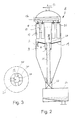
- Fig. 2 is simplified, the apparatus 8 shown in section, which is formed from a combination of the cyclone 9 with the candle filter 10.
- the cyclone 9 is supplied via a cyclone inlet 16 with the particles laden gases, wherein due to the different pressure ratios, the majority of the particles is deposited down.
- the thus pre-cleaned gases flow in the central tube of the cyclone separator 9 upwards into the candle filter area 10 and are cleaned by means of the candle filter designated 17.
- the gas thus purified flows through safety filters still located at the top of the candle filters, designated by 18, in order then to leave the apparatus 8 according to arrow 12.
- the candle filter If the candle filter is cleaned, for example, by means of recirculated quenching gas via the line 14a, it falls to the filter adhering dust on the inclined downwardly inclined separating tray 19 between the cyclone 9 and candle filter portion 10, wherein the central tube 20 of the cyclone has an internal installation in the bottom portion 19, the in Fig. 3 is shown slightly enlarged.
- Spoke-mounted fine dust discharge pipes 24 lead from the bottom 19 into the central discharge pipe 21, which passes through the cyclone 9 and ends at the bottom in a dust discharge 22, where the dust is supplied to a dust collector 23 via corresponding locks.
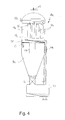
- Fig. 4 a modified embodiment is shown.
- the discharge pipe 21a for the fine dust from the filter cartridge portion 10a of the apparatus 8a is arranged laterally, below the filter cartridges 17a in this example, an eccentric, sloping bottom plate 19a is provided, on which falls when cleaning the filter cartridges 17a of the fine dust and discharged laterally.
- the gas which flows through the central tube 20a of the cyclone 9a is supplied to the filter cartridges 17a via an eccentrically arranged passage 25.
- the filter cartridges 17a are like the filter cartridges 17 ( Fig. 1 ) are equipped with catalytically active safety filters 26 in their downstream end region. Otherwise, the same functionally identical elements in the embodiment of Fig. 4 provided with the same reference numerals as in Fig. 2 ,
Landscapes
- Chemical & Material Sciences (AREA)
- Engineering & Computer Science (AREA)
- Combustion & Propulsion (AREA)
- Oil, Petroleum & Natural Gas (AREA)
- Chemical Kinetics & Catalysis (AREA)
- General Chemical & Material Sciences (AREA)
- Organic Chemistry (AREA)
- Environmental & Geological Engineering (AREA)
- Health & Medical Sciences (AREA)
- Biomedical Technology (AREA)
- Analytical Chemistry (AREA)
- Industrial Gases (AREA)
- Cyclones (AREA)
- Devices And Processes Conducted In The Presence Of Fluids And Solid Particles (AREA)
Abstract
Description
- Bei der Vergasung fossiler Brennstoffe, wie beispielsweise Stein- oder Braunkohle, Biomassen, Raffinerierückständen reagiert das enthaltene Chlor oder Schwefel zu sauren Gasen, was zu erosiven oder korrosiven Problemen bei den nachgeschalteten Anlagekomponeten führt. Bei der Vergasung von Biomassen fallen zudem noch beträchtliche Mengen an Teeren an, die es zu entfernen gilt, da die Teerkondensate ebenfalls in nachgeschalteten Anlagen zu erheblichen Problemen führen können. Aus der
EP 1 870 444 A2 ist ein Reinigungsverfahren von Gasen aus einem Holzvergaser bekannt, das Filterkerzen einsetzt und dem Produktgas mehr Zeit für chemische Reaktionen vor den Filterkerzen lässt. Eine Zyklonabscheidung ist dort nicht vorgesehen. - Eine mögliche Abscheidung von sauren Schadgasen kann auch dadurch erfolgen, dass nasse Waschverfahren eingesetzt werden, was aber den Nachteil hat, dass die Gase stark abgekühlt werden müssen. Eine Teerabscheidung wird als sogenannte katalytische Abscheidung in separaten katalytischen Teerabscheidern durchgeführt, wobei ein derartiger Apparat in der Regel der H2S-Abscheidung und der Entstaubung nachgeschaltet ist. Wird ein entsprechender Katalysator dem Filter vorgeschaltet, so ist es notwendig, dass das Synthesegas aufgrund der Wärmeverluste wieder auf die Betriebstemperatur zwischen 800°C und 1000°C aufgeheizt werden muss, was zu hohen Wirkungsgradverlusten und zu einem entsprechend hohen technischen Aufwand führt.
- Aufgabe der Erfindung ist es, ein wirtschaftliches Verfahren mit einer entsprechenden Anlage zu schaffen, die eine sichere Abtrennung von sauren Verbindungen HF, HCl, H2S, Staub und Teer in einem möglichst hohen Temperaturbereich ermöglicht.
- Mit einem Verfahren der eingangs bezeichneten Art wird diese Aufgabe gemäß der Erfindung dadurch gelöst, dass der aus der Vergasung austretende über 700°C heiße Medienstrom mit Additiven einer Entschwefelung und nachfolgend einem kombinierten Zyklon mit zugeordneten Filterkerzen in einem gemeinsamen Gefäß zugeführt wird und das Gas zur weiteren Nutzung hinter den Filterkerzen abgezogen wird.
- Mit der Erfindung wird erreicht, dass durch die kombinierte Abscheidung der Feststoffe in einem gemeinsamen Apparat bei hoher Temperatur geringere Wärmeverluste zu erreichen sind, wobei gleichzeitig die Additivzugabe je nach Verfahrensweise an unterschiedlichen Positionen erfolgen kann:
- Die Zugabe von Additiven kann entweder gleichzeitig mit dem Brennstoff oder im Vergaserbereich oder mit rezirkuliertem Quenchgas, wie dies beispielsweise in der
DE 10 2008 049 579 der Anmelderin beschrieben ist, erfolgen, wobei grundsätzlich auch die Möglichkeit besteht, die Additive insbesondere vor der Entstaubung je nach Verfahrensablauf zuzuführen. - In Ausgestaltung ist nach der Erfindung vorgesehen, dass eine Separierung von sauren Gaskomponenten, z.B. eine H2S-Abscheidung, vor der Entstaubung durch Additivzugabe vorgenommen wird.
- Eine weitere Ausgestaltung der Erfindung besteht darin, dass eine Teerabscheidung durch Zugabe von Additiven vor der Entstaubung vorgenommen wird oder dass eine Restteerabscheidung an und/oder innerhalb der Kerzenfilter vorgenommen wird.
- Zur Lösung der oben angegebenen Aufgabe sieht die Erfindung auch eine Anlage zur Abscheidung von sauren Komponenten, Staub und Teer aus heißen Abgasen von Vergasungsanlagen vor, die sich dadurch auszeichnet, dass ein Zyklonabscheider und ein Kerzenfilter innerhalb eines Gefäßes in Schwerkraftrichtung übereinander vorgesehen sind, wobei das Zentralrohr des Zyklonabscheiders in den mit Filterkerzen bestückten Filterraum geführt ist.
- Die Zuordnung des Zyklonabscheiders und der Kerzenfilter innerhalb eines Gerätes mit der erfindungsgemäßen Positionierung führt zu geringen Strömungsverlusten bei gleichzeitig hoher Effizienz.
- An dieser Stelle sei bemerkt, dass für sich gesehen Kombinationsgeräte aus Filter und Zyklon bekannt sind, z.B. aus dem deutschen Gebrauchsmuster 1 879 283, wobei dort besonders auf die Feinstaubaustragung keine Rücksicht genommen wird. Kleinbauende Filter entsprechender Bauweise zeigen auch die
DE 26 22 938 B ,DE 32 30 709 A oderDE 34 22 592 A , um nur einige Beispiele zu nennen. Abgewandelte Ausgestaltungen zeigen dieUS 2 941 621 oder dieWO83/03556 - In Ausgestaltung sieht die Erfindung vor, dass die Trennwand zwischen Zyklonabscheider und Filterraum als trichterförmiger Boden ausgebildet ist, der vom Zentralrohr des Zyklonabscheiders durchsetzt ist, wobei im Zentralrohr ein im Durchmesser kleineres Fallrohr für Feinstaub positioniert ist, mit Zuführelementen für den Feinstaub vom Trichterboden in das Fallrohr.
- Diese spezielle Gestaltung einer erfindungsgemäßen Anlage zeichnet sich zusätzlich dadurch aus, dass die Zuführelemente als speichenförmig angeordnete Rohrstutzen zwischen Kopfbereich des Fallrohres und dem Zentralrohr im Tiefpunkt des Trichterbodens ausgebildet sind.
- Eine etwas abgewandelte Ausführungsform einer entsprechenden Anlage besteht nach der Erfindung darin, dass auf Abstand zum Zentralrohr im Filteraum ein Schrägboden vorgesehen ist mit einem seitlichen Abzug für den Feinstaub und einem exzentrischen Durchlass für das Zentralrohr durchströmende Gas.
- Die Erfindung sieht auch unabhängig von der Apparatgestaltung vor, dass die Filterkerzen mit einer katalytischen Beschichtung und/oder einer katalytischen Füllung ausgerüstet sind.
- Weitere Merkmale, Einzelheiten und Vorteile der Erfindung ergeben sich aufgrund der nachfolgenden Beschreibung sowie anhand der Zeichnung, diese zeigt in
- Fig. 1
- ein Prinzipschaltbild einer Anlage zur Durchführung des erfindungsgemäßen Verfahrens,
- Fig. 2
- in vereinfachter Schnittdarstellung eine Apparateausführung nach der Erfindung,
- Fig. 3
- eine leicht vergrößerte Teilaufsicht auf das Zentralrohr gemäß Pfeil III in
Fig. 2 sowie in - Fig. 4
- in Darstellung
Fig. 2 eine abgewandelte Apparateausführung. - Die in
Fig. 1 allgemein mit 1 bezeichnete Anlage ist dort als Prinzipschaltbild dargestellt. Dabei werden dort einem Vergaser 2 Brennstoff (punktierter Pfeil 3), Sauerstoff (durchgezogener Pfeil 4) und ggf. Additive (gestrichelter Pfeil 5) zugeführt. Der Schlackeabzug ist mit 6 bezeichnet. Dem Vergaser 2 folgt eine Entschwefelung 7 und nachfolgend der Apparat 8, in dem ein Zyklon 9 und ein Kerzenfilterbereich 10 zusammengefasst sind. - Die Gaszufuhr in den Zyklon 9 ist mit einem Pfeil 11 bezeichnet, der Nutzgasauslass hinter dem Kerzenfilter 10 mit einem Pfeil 12. Das Nutzgas, allgemein mit 13 bezeichnet, wird dann einer weiteren Verarbeitung zugeführt.
- Eine Quenchgasrückführung aus dem Strom 12 in einem Bereich vor der Entschwefelung 7 ist mit einem gestrichelten Pfeil 14 wiedergegeben. In diesem Bereich vor der Entschwefelung kann auch ein Additiv zugeführt werden, was mit einem gestrichelten Pfeil 15 angedeutet ist.
- Erkennbar kann beispielsweise die Abscheidung saurer Gaskomponenten, z.B. eine H2S-Abscheidung vor der Entstaubung mittels Additivzugabe (Vergaser und/oder mit Quenchgas) erfolgen. Eine Teerabscheidung vor der Entstaubung durch Additive ist ebenfalls möglich, wobei die Vorababscheidung dieser Additive und des Staubes im Zyklon und eine Feinstaubabscheidung im Kerzenfilter erfolgt.
- Möglich ist auch die Restabscheidung der Teere an und/oder innerhalb der Kerzenfilter, wobei den Kerzenfiltern am Austritt ein Sicherheitsfilter, z.B. aus Schaumkeramik, nachgeschaltet sein kann. Diese Sicherheitsfilter können auch katalytisch aktiv sein. Das Quenchgas, beispielsweise angedeutet durch einen Teilstrom 14a, kann zur Abreinigung der Filterkerzen verwendet werden, wie nachfolgend noch dargestellt.
- In
Fig. 2 ist vereinfacht der Apparat 8 im Schnitt dargestellt, der aus einer Kombination des Zyklons 9 mit dem Kerzenfilter 10 gebildet ist. Dem Zyklon 9 werden über einen Zykloneintritt 16 die mit Partikeln beladenen Gase zugeführt, wobei aufgrund der unterschiedlichen Druckverhältnisse die Mehrzahl der Partikel nach unten abgesetzt wird. Die so vorgereinigten Gase strömen im Zentralrohr des Zyklonabscheiders 9 nach oben in den Kerzenfilterbereich 10 und werden mittels der mit 17 bezeichneten Kerzenfilter abgereinigt. Das so gereinigte Gas durchströmt noch am Kopf der Kerzenfilter befindliche Sicherheitsfilter, mit 18 bezeichnet, um dann gemäß Pfeil 12 den Apparat 8 zu verlassen. - Werden die Kerzenfilter z.B. mittels rückgeführten Quenchgases über die Leitung 14a abgereinigt, fällt der an den Filter haftende Staub auf den schräg nach unten geneigten Trennboden 19 zwischen Zyklon 9 und Kerzenfilterbereich 10, wobei das Zentralrohr 20 des Zyklons einen inneren Einbau im Bodenbereich 19 aufweist, der in
Fig. 3 etwas vergrößert dargestellt ist. - Speichenangeordnete Feinstaubaustragsrohre 24 führen vom Boden 19 in das zentrische Abführrohr 21, welches den Zyklon 9 durchsetzt und unten in einem Staubaustrag 22 endet, wobei dort über entsprechende Schleusen der Staub einem Staubsammler 23 zugeführt wird.
- In
Fig. 4 ist ein abgewandeltes Ausführungsbeispiel dargestellt. Hier ist das Austragsrohr 21a für den Feinstaub aus dem Filterkerzenbereich 10a des Apparates 8a seitlich angeordnet, wobei unterhalb der Filterkerzen 17a in diesem Beispiel eine exzentrische, schräge Bodenplatte 19a vorgesehen ist, auf die beim Abreinigen der Filterkerzen 17a der Feinstaub fällt und seitlich ausgeleitet wird. Das Gas, welches das Zentralrohr 20a des Zyklons 9a durchströmt, wird über einen exzentrisch angeordneten Durchlass 25 den Filterkerzen 17a zugeführt. Die Filterkerzen 17a sind ebenso wie die Filterkerzen 17 (Fig. 1 ) in ihrem stromabwärtigen Endbereich mit katalytisch aktiven Sicherheitsfiltern 26 ausgerüstet. Ansonsten sind die funktionsmäßig gleichen Elemente beim Ausführungsbeispiel derFig. 4 mit den gleichen Bezugszeichen versehen wie inFig. 2 . - Natürlich sind die beschriebenen Ausführungsbeispiele der Erfindung noch in vielfacher Hinsicht abzuändern, ohne den Grundgedanken zu verlassen, so stellen die
Fig. 2 bis 4 lediglich stark vereinfacht die entsprechenden Apparate 8 bzw. 8a dar, welche für die Erfindung wesentlich als Kombiabscheider gestaltet sind.
Claims (6)
- Anlage, insbesondere zur Durchführung eines Verfahrens zur Abscheidung von sauren Komponenten, Staub und Teer aus heißen Gasen von Vergasungsanlagen,
dadurch gekennzeichnet,
dass ein Zyklonabscheider (9) und ein Kerzenfilter (10) innerhalb eines Gefäßes (8) in Schwerkraftrichtung übereinander vorgesehen sind, wobei das Zentralrohr (20) des Zyklonabscheiders (9) in den mit Filterkerzen (17) bestückten Filterraum (10) geführt ist. - Anlage nach Anspruch 1,
dadurch gekennzeichnet,
dass die Trennwand (19) zwischen Zyklonabscheider (9) und Filterraum (10) als trichterförmiger Boden ausgebildet ist, der vom Zentralrohr (20) des Zyklonabscheiders (9) durchsetzt ist, wobei im Zentralrohr (20) ein im Durchmesser kleineres Fallrohr (21) für Feinstaub positioniert ist mit Zuführelementen (24) für den Feinstaub vom Trichterboden (19) in das Fallrohr (21). - Anlage nach Anspruch 2,
dadurch gekennzeichnet,
dass die Zuführelemente als speichenförmig angeordnete Rohrstutzen (24) zwischen Kopfbereich des Fallrohres (21) und dem Zentralrohr (20) im Tiefpunkt des Trichterbodens (19) ausgebildet sind. - Anlage nach Anspruch 1,
dadurch gekennzeichnet,
dass auf Abstand zum Zentralrohr (20a) im Filterraum (10a) ein Schrägboden (19a) vorgesehen ist mit einem seitlichen Abzug (21a) für den Feinstaub und einem exzentrischen Durchlass (25) für das das Zentralrohr (20a) durchströmende Gas. - Anlage nach Anspruch 1 oder einem der folgenden Ansprüche,
dadurch gekennzeichnet,
dass die Filterkerzen (17,17a) mit einer katalytischen Beschichtung und/oder einer katalytischen Füllung ausgerüstet sind. - Anlage nach Anspruch 5,
dadurch gekennzeichnet,
dass jede Filterkerze (17,17a) mit einem katalytisch aktiven Sicherheitsfilter (26) ausgerüstet ist.
Applications Claiming Priority (2)
| Application Number | Priority Date | Filing Date | Title |
|---|---|---|---|
| DE102009058656A DE102009058656A1 (de) | 2009-12-16 | 2009-12-16 | Verfahren und Anlage zur Abscheidung von sauren Komponenten, Staub und Teer aus heißen Gasen von Vergasungsanlagen |
| EP10781615.9A EP2512621B1 (de) | 2009-12-16 | 2010-11-13 | Verfahren zur abscheidung von sauren komponenten, staub und teer aus heissen gasen von vergasungsanlagen |
Related Parent Applications (3)
| Application Number | Title | Priority Date | Filing Date |
|---|---|---|---|
| EP10781615.9A Division-Into EP2512621B1 (de) | 2009-12-16 | 2010-11-13 | Verfahren zur abscheidung von sauren komponenten, staub und teer aus heissen gasen von vergasungsanlagen |
| EP10781615.9A Division EP2512621B1 (de) | 2009-12-16 | 2010-11-13 | Verfahren zur abscheidung von sauren komponenten, staub und teer aus heissen gasen von vergasungsanlagen |
| EP10781615.9 Division | 2010-11-13 |
Publications (2)
| Publication Number | Publication Date |
|---|---|
| EP2591841A1 true EP2591841A1 (de) | 2013-05-15 |
| EP2591841B1 EP2591841B1 (de) | 2015-09-23 |
Family
ID=43500031
Family Applications (2)
| Application Number | Title | Priority Date | Filing Date |
|---|---|---|---|
| EP13154396.9A Not-in-force EP2591841B1 (de) | 2009-12-16 | 2010-11-13 | Anlage zur Abscheidung von sauren Komponenten, Staub und Teer aus heißen Gasen von Vergasungsanlagen |
| EP10781615.9A Not-in-force EP2512621B1 (de) | 2009-12-16 | 2010-11-13 | Verfahren zur abscheidung von sauren komponenten, staub und teer aus heissen gasen von vergasungsanlagen |
Family Applications After (1)
| Application Number | Title | Priority Date | Filing Date |
|---|---|---|---|
| EP10781615.9A Not-in-force EP2512621B1 (de) | 2009-12-16 | 2010-11-13 | Verfahren zur abscheidung von sauren komponenten, staub und teer aus heissen gasen von vergasungsanlagen |
Country Status (16)
| Country | Link |
|---|---|
| US (1) | US9498746B2 (de) |
| EP (2) | EP2591841B1 (de) |
| KR (1) | KR20120092167A (de) |
| CN (1) | CN102655926B (de) |
| AU (1) | AU2010341226B2 (de) |
| BR (1) | BR112012014561A2 (de) |
| CA (1) | CA2784448C (de) |
| CL (1) | CL2012001592A1 (de) |
| DE (1) | DE102009058656A1 (de) |
| ES (1) | ES2553706T3 (de) |
| PL (1) | PL2512621T3 (de) |
| RU (1) | RU2544663C2 (de) |
| TW (1) | TWI517892B (de) |
| UA (1) | UA110201C2 (de) |
| WO (1) | WO2011082729A1 (de) |
| ZA (1) | ZA201205176B (de) |
Families Citing this family (11)
| Publication number | Priority date | Publication date | Assignee | Title |
|---|---|---|---|---|
| TWI627130B (zh) * | 2012-04-18 | 2018-06-21 | 美商艾克頌美孚上游研究公司 | 由連續反應器流出物移出碳奈米管之方法 |
| CN102796561B (zh) * | 2012-08-09 | 2014-04-30 | 武汉凯迪工程技术研究总院有限公司 | 生物质燃料二氧化碳循环无氧气化方法及设备 |
| KR101677421B1 (ko) * | 2015-03-13 | 2016-11-18 | (주)청류에프앤에스 | 재순환식 미세먼지 및 수분 저감장치 |
| US10982151B2 (en) | 2016-09-29 | 2021-04-20 | Expander Energy Inc. | Process for converting carbonaceous material into low tar synthesis gas |
| CN106422557A (zh) * | 2016-11-01 | 2017-02-22 | 大唐环境产业集团股份有限公司 | 一种用于脱除生物质气化焦油的滤芯、过滤系统及方法 |
| SE543205C2 (sv) * | 2019-03-03 | 2020-10-20 | Scanmaskin Sverige Ab | En filterbaserad dammavskiljare med integrerad förseparator |
| CN109806703B (zh) * | 2019-03-11 | 2020-04-28 | 西安交通大学 | 一种含尘油气的除尘装置及除尘方法 |
| CN110846084B (zh) * | 2019-11-29 | 2024-03-12 | 北京航天迈未科技有限公司 | 一种粉尘分离回收设备及方法 |
| CN112375579B (zh) * | 2020-11-06 | 2022-01-25 | 深圳芯闻科技有限公司 | 一种连续式炭化炉烟气净化系统 |
| CN113403116A (zh) * | 2021-07-30 | 2021-09-17 | 中冶赛迪技术研究中心有限公司 | 复合式煤气干法净化装置 |
| CN114806648A (zh) * | 2022-06-27 | 2022-07-29 | 山西阳煤化工机械(集团)有限公司 | 粗煤气分离器和粗煤气分离方法 |
Citations (12)
| Publication number | Priority date | Publication date | Assignee | Title |
|---|---|---|---|---|
| US2941621A (en) | 1957-07-19 | 1960-06-21 | Shell Oil Co | Centrifugal separators |
| GB1236017A (en) * | 1967-06-13 | 1971-06-16 | Plenty & Son Ltd | Improvements in and relating to gas filters with preliminary cyclone separation |
| DE2622938B2 (de) | 1975-05-23 | 1980-08-28 | Snamprogetti S.P.A., Mailand (Italien) | Zweistufiger Zyklon-Filter-Abscheider |
| FR2515061A1 (fr) * | 1981-10-22 | 1983-04-29 | Giai Gilbert | Epurateur d'air |
| WO1983003556A1 (en) | 1982-04-07 | 1983-10-27 | Haberl, Johann | Cyclone separator with filter unit |
| DE3230709A1 (de) | 1982-08-18 | 1984-02-23 | Alkem Gmbh, 6450 Hanau | Staubzyklon und verfahren zum betrieb eines solchen staubzyklons |
| DE3422592A1 (de) | 1984-06-18 | 1986-04-24 | Frank 6148 Heppenheim Titus | Zyklon-filter mit ganzmetall-tandem-filterkerze |
| JP2000303078A (ja) * | 1999-04-21 | 2000-10-31 | Babcock Hitachi Kk | 石炭ガス化プラントのチャー回収装置 |
| KR20040090182A (ko) * | 2003-04-16 | 2004-10-22 | 한국에너지기술연구원 | 먼지부하저감형 미세먼지/질소산화물 동시제거용여과집진장치 |
| EP1762292A1 (de) * | 2005-09-13 | 2007-03-14 | Mann+Hummel Gmbh | Einrichtung zur Reinigung von Luft |
| EP1870444A2 (de) | 2006-06-20 | 2007-12-26 | Walter Kuntschar | Verfahren zur Reinigung von Gasen aus einem Holzvergaser und Filter hierfür |
| DE102008049579A1 (de) | 2008-09-30 | 2010-04-01 | Uhde Gmbh | Heißgasreinigung |
Family Cites Families (10)
| Publication number | Priority date | Publication date | Assignee | Title |
|---|---|---|---|---|
| US3025041A (en) * | 1958-08-21 | 1962-03-13 | Continental Copper & Steel Ind | Vapor liquid contacting devices |
| DE1879283U (de) | 1963-06-28 | 1963-09-12 | Walther & Cie Ag | Staubabscheider mit filter und vorgeschaltetem zyklon fuer gase, insbesondere druckgase. |
| HK1048647B (en) * | 1999-08-19 | 2006-05-04 | Manufacturing And Technology Conversion International, Inc. | System integration of a steam reformer and fuel cell |
| FI112952B (fi) * | 2001-12-21 | 2004-02-13 | Foster Wheeler Energia Oy | Menetelmä ja laitteisto hiilipitoisen materiaalin kaasuttamiseksi |
| EP1567618A2 (de) * | 2002-05-22 | 2005-08-31 | Manufacturing And Technology Conversion International, Inc. | Pulsvergasung und heissgasreinigungsapparatur und -verfahren |
| DE102006017353A1 (de) | 2006-04-11 | 2007-10-18 | Spot Spirit Of Technology Ag | Verfahren und Vorrichtung zur prozessintegrierten heißen Gasreinigung von Staub- und gasförmigen Inhaltsstoffen eines Synthesegases |
| US7610793B2 (en) * | 2006-09-11 | 2009-11-03 | Cummins Filtration Ip Inc. | Residence time chamber and sampling apparatus |
| WO2008055591A2 (de) | 2006-11-09 | 2008-05-15 | Paul Scherrer Institut | Verfahren und anlage zur verstromung fester biomasse |
| US7691182B1 (en) * | 2006-12-12 | 2010-04-06 | University Of Central Florida Research Foundation, Inc. | Process for hydrogen production via integrated processing of landfill gas and biomass |
| DE102008021081A1 (de) * | 2008-04-28 | 2009-10-29 | Süd-Chemie AG | Verfahren zur katalytischen Verringerung des Teergehalts in Gasen aus Vergasungsprozessen unter Verwendung eines Katalysators auf Edelmetallbasis |
-
2009
- 2009-12-16 DE DE102009058656A patent/DE102009058656A1/de not_active Ceased
-
2010
- 2010-11-13 RU RU2012129660/05A patent/RU2544663C2/ru not_active IP Right Cessation
- 2010-11-13 PL PL10781615T patent/PL2512621T3/pl unknown
- 2010-11-13 KR KR1020127017063A patent/KR20120092167A/ko not_active Abandoned
- 2010-11-13 ES ES13154396.9T patent/ES2553706T3/es active Active
- 2010-11-13 EP EP13154396.9A patent/EP2591841B1/de not_active Not-in-force
- 2010-11-13 AU AU2010341226A patent/AU2010341226B2/en not_active Ceased
- 2010-11-13 UA UAA201208476A patent/UA110201C2/ru unknown
- 2010-11-13 CA CA2784448A patent/CA2784448C/en not_active Expired - Fee Related
- 2010-11-13 WO PCT/EP2010/006922 patent/WO2011082729A1/de not_active Ceased
- 2010-11-13 EP EP10781615.9A patent/EP2512621B1/de not_active Not-in-force
- 2010-11-13 CN CN201080056923.9A patent/CN102655926B/zh not_active Expired - Fee Related
- 2010-11-13 US US13/516,346 patent/US9498746B2/en not_active Expired - Fee Related
- 2010-11-13 BR BR112012014561A patent/BR112012014561A2/pt not_active Application Discontinuation
- 2010-11-23 TW TW099140345A patent/TWI517892B/zh not_active IP Right Cessation
-
2012
- 2012-06-13 CL CL2012001592A patent/CL2012001592A1/es unknown
- 2012-07-12 ZA ZA2012/05176A patent/ZA201205176B/en unknown
Patent Citations (12)
| Publication number | Priority date | Publication date | Assignee | Title |
|---|---|---|---|---|
| US2941621A (en) | 1957-07-19 | 1960-06-21 | Shell Oil Co | Centrifugal separators |
| GB1236017A (en) * | 1967-06-13 | 1971-06-16 | Plenty & Son Ltd | Improvements in and relating to gas filters with preliminary cyclone separation |
| DE2622938B2 (de) | 1975-05-23 | 1980-08-28 | Snamprogetti S.P.A., Mailand (Italien) | Zweistufiger Zyklon-Filter-Abscheider |
| FR2515061A1 (fr) * | 1981-10-22 | 1983-04-29 | Giai Gilbert | Epurateur d'air |
| WO1983003556A1 (en) | 1982-04-07 | 1983-10-27 | Haberl, Johann | Cyclone separator with filter unit |
| DE3230709A1 (de) | 1982-08-18 | 1984-02-23 | Alkem Gmbh, 6450 Hanau | Staubzyklon und verfahren zum betrieb eines solchen staubzyklons |
| DE3422592A1 (de) | 1984-06-18 | 1986-04-24 | Frank 6148 Heppenheim Titus | Zyklon-filter mit ganzmetall-tandem-filterkerze |
| JP2000303078A (ja) * | 1999-04-21 | 2000-10-31 | Babcock Hitachi Kk | 石炭ガス化プラントのチャー回収装置 |
| KR20040090182A (ko) * | 2003-04-16 | 2004-10-22 | 한국에너지기술연구원 | 먼지부하저감형 미세먼지/질소산화물 동시제거용여과집진장치 |
| EP1762292A1 (de) * | 2005-09-13 | 2007-03-14 | Mann+Hummel Gmbh | Einrichtung zur Reinigung von Luft |
| EP1870444A2 (de) | 2006-06-20 | 2007-12-26 | Walter Kuntschar | Verfahren zur Reinigung von Gasen aus einem Holzvergaser und Filter hierfür |
| DE102008049579A1 (de) | 2008-09-30 | 2010-04-01 | Uhde Gmbh | Heißgasreinigung |
Also Published As
| Publication number | Publication date |
|---|---|
| KR20120092167A (ko) | 2012-08-20 |
| PL2512621T3 (pl) | 2018-03-30 |
| RU2012129660A (ru) | 2014-01-27 |
| ZA201205176B (en) | 2013-01-31 |
| CN102655926A (zh) | 2012-09-05 |
| CN102655926B (zh) | 2015-01-14 |
| EP2512621B1 (de) | 2017-07-12 |
| WO2011082729A1 (de) | 2011-07-14 |
| AU2010341226A1 (en) | 2012-07-05 |
| EP2591841B1 (de) | 2015-09-23 |
| RU2544663C2 (ru) | 2015-03-20 |
| UA110201C2 (en) | 2015-12-10 |
| CL2012001592A1 (es) | 2014-04-25 |
| TWI517892B (zh) | 2016-01-21 |
| AU2010341226B2 (en) | 2015-10-01 |
| EP2512621A1 (de) | 2012-10-24 |
| BR112012014561A2 (pt) | 2016-08-16 |
| ES2553706T3 (es) | 2015-12-11 |
| CA2784448C (en) | 2018-06-19 |
| DE102009058656A1 (de) | 2011-06-22 |
| US9498746B2 (en) | 2016-11-22 |
| TW201124194A (en) | 2011-07-16 |
| US20120269708A1 (en) | 2012-10-25 |
| CA2784448A1 (en) | 2011-07-14 |
Similar Documents
| Publication | Publication Date | Title |
|---|---|---|
| EP2512621B1 (de) | Verfahren zur abscheidung von sauren komponenten, staub und teer aus heissen gasen von vergasungsanlagen | |
| DE3102819C2 (de) | ||
| DE69300263T2 (de) | Vorrichtung zum Filtern von Feststoffpartikeln aus einem Fluid. | |
| DE1758357A1 (de) | Vorrichtung zum Abschrecken und/oder Waschen von Heissgasen | |
| WO2011085908A1 (de) | Anlage und verfahren zur reinigung von schiffsdieselabgasen | |
| DE102007042543A1 (de) | Verfahren und Vorrichtung zur Behandlung von beladenem Heißgas | |
| EP3065850A1 (de) | Verfahren zur reinigung von bypassgasen der zement- oder mineralsindustrie sowie anlage der zement- oder mineralsindustrie | |
| DE19521321A1 (de) | Verfahren und Vorrichtung zur Reduktion des Staubgehaltes der Abgase eines Dampferzeugers | |
| DE102011052788B4 (de) | Verfahren und Vorrichtung zur Reinigung von Abgasen | |
| EP2804686A1 (de) | Verfahren zum sedimentieren von segmentpartikeln in einem verfahren zur gewinnung von dieselöl | |
| DE10002584B4 (de) | Verfahren und Vorrichtung zur Filtration von Gasen | |
| DE102014005152A1 (de) | Abgasnachbehandlungssystem und Verfahren zur Abgasnachbehandlung | |
| DE69931924T2 (de) | Verfahren zur reinigung von abgas | |
| EP3046998A1 (de) | Verfahren und anlage zur zumindest teilweisen vergasung von festem, organischen einsatzmaterial | |
| DE102014203639A1 (de) | Staubabscheidung aus dem Rohgas einer Flugstromvergasung | |
| AT509865B1 (de) | Verfahren zur herstellung von roheisen oder flüssigen stahlvorprodukten | |
| DE2406314C3 (de) | Vorrichtung zum Absaugen, Verbrennen und Auswaschen von Gas zur Verwendung an einem Koksofen | |
| DE112010002581B4 (de) | Rauchgasreinigungsanlage mit Düsenvariation | |
| EP2263779B1 (de) | Rauchgasreinigunsanlage mit Auslasseinheit | |
| WO2014131700A1 (de) | Verfahren zur weiterverwertung von nebenprodukten aus vergasungsanlagen | |
| EP3072573B1 (de) | Gasreinigungsanlage und verfahren zur reinigung von gasen mit rückführung von gereinigtem gas | |
| WO2021123160A1 (de) | Verfahren und anlage zur herstellung von kohlenwasserstoffen | |
| DE102007027601A1 (de) | Herstellung und Kühlung von gasförmigen Kohlevergasungsprodukten | |
| AT515104B1 (de) | Vorrichtung zur Aufbereitung von metallionenhältigen Lösungen | |
| WO2018091371A1 (de) | Produktgasfilter umfassend filterkerzen und eine zeolith-einspeisung |
Legal Events
| Date | Code | Title | Description |
|---|---|---|---|
| PUAI | Public reference made under article 153(3) epc to a published international application that has entered the european phase |
Free format text: ORIGINAL CODE: 0009012 |
|
| AC | Divisional application: reference to earlier application |
Ref document number: 2512621 Country of ref document: EP Kind code of ref document: P |
|
| AK | Designated contracting states |
Kind code of ref document: A1 Designated state(s): AL AT BE BG CH CY CZ DE DK EE ES FI FR GB GR HR HU IE IS IT LI LT LU LV MC MK MT NL NO PL PT RO RS SE SI SK SM TR |
|
| AX | Request for extension of the european patent |
Extension state: BA ME |
|
| 17P | Request for examination filed |
Effective date: 20131025 |
|
| RBV | Designated contracting states (corrected) |
Designated state(s): AL AT BE BG CH CY CZ DE DK EE ES FI FR GB GR HR HU IE IS IT LI LT LU LV MC MK MT NL NO PL PT RO RS SE SI SK SM TR |
|
| 17Q | First examination report despatched |
Effective date: 20131218 |
|
| RAP1 | Party data changed (applicant data changed or rights of an application transferred) |
Owner name: THYSSENKRUPP INDUSTRIAL SOLUTIONS AG |
|
| GRAP | Despatch of communication of intention to grant a patent |
Free format text: ORIGINAL CODE: EPIDOSNIGR1 |
|
| INTG | Intention to grant announced |
Effective date: 20150515 |
|
| GRAS | Grant fee paid |
Free format text: ORIGINAL CODE: EPIDOSNIGR3 |
|
| GRAA | (expected) grant |
Free format text: ORIGINAL CODE: 0009210 |
|
| AC | Divisional application: reference to earlier application |
Ref document number: 2512621 Country of ref document: EP Kind code of ref document: P |
|
| AK | Designated contracting states |
Kind code of ref document: B1 Designated state(s): AL AT BE BG CH CY CZ DE DK EE ES FI FR GB GR HR HU IE IS IT LI LT LU LV MC MK MT NL NO PL PT RO RS SE SI SK SM TR |
|
| REG | Reference to a national code |
Ref country code: GB Ref legal event code: FG4D Free format text: NOT ENGLISH |
|
| REG | Reference to a national code |
Ref country code: CH Ref legal event code: EP |
|
| REG | Reference to a national code |
Ref country code: AT Ref legal event code: REF Ref document number: 750916 Country of ref document: AT Kind code of ref document: T Effective date: 20151015 |
|
| REG | Reference to a national code |
Ref country code: IE Ref legal event code: FG4D Free format text: LANGUAGE OF EP DOCUMENT: GERMAN |
|
| REG | Reference to a national code |
Ref country code: DE Ref legal event code: R096 Ref document number: 502010010367 Country of ref document: DE |
|
| REG | Reference to a national code |
Ref country code: FR Ref legal event code: PLFP Year of fee payment: 6 |
|
| REG | Reference to a national code |
Ref country code: ES Ref legal event code: FG2A Ref document number: 2553706 Country of ref document: ES Kind code of ref document: T3 Effective date: 20151211 |
|
| REG | Reference to a national code |
Ref country code: SE Ref legal event code: TRGR |
|
| REG | Reference to a national code |
Ref country code: NL Ref legal event code: FP |
|
| PG25 | Lapsed in a contracting state [announced via postgrant information from national office to epo] |
Ref country code: FI Free format text: LAPSE BECAUSE OF FAILURE TO SUBMIT A TRANSLATION OF THE DESCRIPTION OR TO PAY THE FEE WITHIN THE PRESCRIBED TIME-LIMIT Effective date: 20150923 Ref country code: LV Free format text: LAPSE BECAUSE OF FAILURE TO SUBMIT A TRANSLATION OF THE DESCRIPTION OR TO PAY THE FEE WITHIN THE PRESCRIBED TIME-LIMIT Effective date: 20150923 Ref country code: GR Free format text: LAPSE BECAUSE OF FAILURE TO SUBMIT A TRANSLATION OF THE DESCRIPTION OR TO PAY THE FEE WITHIN THE PRESCRIBED TIME-LIMIT Effective date: 20151224 Ref country code: NO Free format text: LAPSE BECAUSE OF FAILURE TO SUBMIT A TRANSLATION OF THE DESCRIPTION OR TO PAY THE FEE WITHIN THE PRESCRIBED TIME-LIMIT Effective date: 20151223 Ref country code: LT Free format text: LAPSE BECAUSE OF FAILURE TO SUBMIT A TRANSLATION OF THE DESCRIPTION OR TO PAY THE FEE WITHIN THE PRESCRIBED TIME-LIMIT Effective date: 20150923 |
|
| REG | Reference to a national code |
Ref country code: LT Ref legal event code: MG4D |
|
| PG25 | Lapsed in a contracting state [announced via postgrant information from national office to epo] |
Ref country code: HR Free format text: LAPSE BECAUSE OF FAILURE TO SUBMIT A TRANSLATION OF THE DESCRIPTION OR TO PAY THE FEE WITHIN THE PRESCRIBED TIME-LIMIT Effective date: 20150923 Ref country code: RS Free format text: LAPSE BECAUSE OF FAILURE TO SUBMIT A TRANSLATION OF THE DESCRIPTION OR TO PAY THE FEE WITHIN THE PRESCRIBED TIME-LIMIT Effective date: 20150923 |
|
| PG25 | Lapsed in a contracting state [announced via postgrant information from national office to epo] |
Ref country code: EE Free format text: LAPSE BECAUSE OF FAILURE TO SUBMIT A TRANSLATION OF THE DESCRIPTION OR TO PAY THE FEE WITHIN THE PRESCRIBED TIME-LIMIT Effective date: 20150923 Ref country code: CZ Free format text: LAPSE BECAUSE OF FAILURE TO SUBMIT A TRANSLATION OF THE DESCRIPTION OR TO PAY THE FEE WITHIN THE PRESCRIBED TIME-LIMIT Effective date: 20150923 Ref country code: SK Free format text: LAPSE BECAUSE OF FAILURE TO SUBMIT A TRANSLATION OF THE DESCRIPTION OR TO PAY THE FEE WITHIN THE PRESCRIBED TIME-LIMIT Effective date: 20150923 Ref country code: IS Free format text: LAPSE BECAUSE OF FAILURE TO SUBMIT A TRANSLATION OF THE DESCRIPTION OR TO PAY THE FEE WITHIN THE PRESCRIBED TIME-LIMIT Effective date: 20160123 |
|
| PG25 | Lapsed in a contracting state [announced via postgrant information from national office to epo] |
Ref country code: PL Free format text: LAPSE BECAUSE OF FAILURE TO SUBMIT A TRANSLATION OF THE DESCRIPTION OR TO PAY THE FEE WITHIN THE PRESCRIBED TIME-LIMIT Effective date: 20150923 Ref country code: RO Free format text: LAPSE BECAUSE OF FAILURE TO SUBMIT A TRANSLATION OF THE DESCRIPTION OR TO PAY THE FEE WITHIN THE PRESCRIBED TIME-LIMIT Effective date: 20150923 Ref country code: PT Free format text: LAPSE BECAUSE OF FAILURE TO SUBMIT A TRANSLATION OF THE DESCRIPTION OR TO PAY THE FEE WITHIN THE PRESCRIBED TIME-LIMIT Effective date: 20160125 |
|
| REG | Reference to a national code |
Ref country code: DE Ref legal event code: R097 Ref document number: 502010010367 Country of ref document: DE |
|
| PG25 | Lapsed in a contracting state [announced via postgrant information from national office to epo] |
Ref country code: MC Free format text: LAPSE BECAUSE OF FAILURE TO SUBMIT A TRANSLATION OF THE DESCRIPTION OR TO PAY THE FEE WITHIN THE PRESCRIBED TIME-LIMIT Effective date: 20150923 Ref country code: LU Free format text: LAPSE BECAUSE OF FAILURE TO SUBMIT A TRANSLATION OF THE DESCRIPTION OR TO PAY THE FEE WITHIN THE PRESCRIBED TIME-LIMIT Effective date: 20151113 |
|
| REG | Reference to a national code |
Ref country code: CH Ref legal event code: PL |
|
| PG25 | Lapsed in a contracting state [announced via postgrant information from national office to epo] |
Ref country code: CH Free format text: LAPSE BECAUSE OF NON-PAYMENT OF DUE FEES Effective date: 20151130 Ref country code: LI Free format text: LAPSE BECAUSE OF NON-PAYMENT OF DUE FEES Effective date: 20151130 |
|
| PLBE | No opposition filed within time limit |
Free format text: ORIGINAL CODE: 0009261 |
|
| STAA | Information on the status of an ep patent application or granted ep patent |
Free format text: STATUS: NO OPPOSITION FILED WITHIN TIME LIMIT |
|
| REG | Reference to a national code |
Ref country code: IE Ref legal event code: MM4A |
|
| 26N | No opposition filed |
Effective date: 20160624 |
|
| PG25 | Lapsed in a contracting state [announced via postgrant information from national office to epo] |
Ref country code: DK Free format text: LAPSE BECAUSE OF FAILURE TO SUBMIT A TRANSLATION OF THE DESCRIPTION OR TO PAY THE FEE WITHIN THE PRESCRIBED TIME-LIMIT Effective date: 20150923 |
|
| PG25 | Lapsed in a contracting state [announced via postgrant information from national office to epo] |
Ref country code: IE Free format text: LAPSE BECAUSE OF NON-PAYMENT OF DUE FEES Effective date: 20151113 |
|
| REG | Reference to a national code |
Ref country code: FR Ref legal event code: PLFP Year of fee payment: 7 |
|
| PG25 | Lapsed in a contracting state [announced via postgrant information from national office to epo] |
Ref country code: SI Free format text: LAPSE BECAUSE OF FAILURE TO SUBMIT A TRANSLATION OF THE DESCRIPTION OR TO PAY THE FEE WITHIN THE PRESCRIBED TIME-LIMIT Effective date: 20150923 |
|
| REG | Reference to a national code |
Ref country code: AT Ref legal event code: MM01 Ref document number: 750916 Country of ref document: AT Kind code of ref document: T Effective date: 20151113 |
|
| PGFP | Annual fee paid to national office [announced via postgrant information from national office to epo] |
Ref country code: FR Payment date: 20161118 Year of fee payment: 7 |
|
| PG25 | Lapsed in a contracting state [announced via postgrant information from national office to epo] |
Ref country code: AT Free format text: LAPSE BECAUSE OF NON-PAYMENT OF DUE FEES Effective date: 20151113 |
|
| PG25 | Lapsed in a contracting state [announced via postgrant information from national office to epo] |
Ref country code: BG Free format text: LAPSE BECAUSE OF FAILURE TO SUBMIT A TRANSLATION OF THE DESCRIPTION OR TO PAY THE FEE WITHIN THE PRESCRIBED TIME-LIMIT Effective date: 20150923 Ref country code: HU Free format text: LAPSE BECAUSE OF FAILURE TO SUBMIT A TRANSLATION OF THE DESCRIPTION OR TO PAY THE FEE WITHIN THE PRESCRIBED TIME-LIMIT; INVALID AB INITIO Effective date: 20101113 Ref country code: SM Free format text: LAPSE BECAUSE OF FAILURE TO SUBMIT A TRANSLATION OF THE DESCRIPTION OR TO PAY THE FEE WITHIN THE PRESCRIBED TIME-LIMIT Effective date: 20150923 |
|
| PG25 | Lapsed in a contracting state [announced via postgrant information from national office to epo] |
Ref country code: CY Free format text: LAPSE BECAUSE OF FAILURE TO SUBMIT A TRANSLATION OF THE DESCRIPTION OR TO PAY THE FEE WITHIN THE PRESCRIBED TIME-LIMIT Effective date: 20150923 |
|
| PG25 | Lapsed in a contracting state [announced via postgrant information from national office to epo] |
Ref country code: BE Free format text: LAPSE BECAUSE OF NON-PAYMENT OF DUE FEES Effective date: 20151130 |
|
| PG25 | Lapsed in a contracting state [announced via postgrant information from national office to epo] |
Ref country code: MT Free format text: LAPSE BECAUSE OF FAILURE TO SUBMIT A TRANSLATION OF THE DESCRIPTION OR TO PAY THE FEE WITHIN THE PRESCRIBED TIME-LIMIT Effective date: 20150923 |
|
| PGFP | Annual fee paid to national office [announced via postgrant information from national office to epo] |
Ref country code: TR Payment date: 20171110 Year of fee payment: 8 Ref country code: NL Payment date: 20171120 Year of fee payment: 8 Ref country code: DE Payment date: 20171121 Year of fee payment: 8 |
|
| PGFP | Annual fee paid to national office [announced via postgrant information from national office to epo] |
Ref country code: GB Payment date: 20171123 Year of fee payment: 8 Ref country code: ES Payment date: 20171220 Year of fee payment: 8 Ref country code: IT Payment date: 20171124 Year of fee payment: 8 Ref country code: SE Payment date: 20171120 Year of fee payment: 8 |
|
| PG25 | Lapsed in a contracting state [announced via postgrant information from national office to epo] |
Ref country code: MK Free format text: LAPSE BECAUSE OF FAILURE TO SUBMIT A TRANSLATION OF THE DESCRIPTION OR TO PAY THE FEE WITHIN THE PRESCRIBED TIME-LIMIT Effective date: 20150923 |
|
| REG | Reference to a national code |
Ref country code: FR Ref legal event code: ST Effective date: 20180731 |
|
| PG25 | Lapsed in a contracting state [announced via postgrant information from national office to epo] |
Ref country code: FR Free format text: LAPSE BECAUSE OF NON-PAYMENT OF DUE FEES Effective date: 20171130 Ref country code: AL Free format text: LAPSE BECAUSE OF FAILURE TO SUBMIT A TRANSLATION OF THE DESCRIPTION OR TO PAY THE FEE WITHIN THE PRESCRIBED TIME-LIMIT Effective date: 20150923 |
|
| REG | Reference to a national code |
Ref country code: DE Ref legal event code: R119 Ref document number: 502010010367 Country of ref document: DE |
|
| REG | Reference to a national code |
Ref country code: SE Ref legal event code: EUG |
|
| REG | Reference to a national code |
Ref country code: NL Ref legal event code: MM Effective date: 20181201 |
|
| GBPC | Gb: european patent ceased through non-payment of renewal fee |
Effective date: 20181113 |
|
| PG25 | Lapsed in a contracting state [announced via postgrant information from national office to epo] |
Ref country code: SE Free format text: LAPSE BECAUSE OF NON-PAYMENT OF DUE FEES Effective date: 20181114 |
|
| PG25 | Lapsed in a contracting state [announced via postgrant information from national office to epo] |
Ref country code: NL Free format text: LAPSE BECAUSE OF NON-PAYMENT OF DUE FEES Effective date: 20181201 |
|
| PG25 | Lapsed in a contracting state [announced via postgrant information from national office to epo] |
Ref country code: IT Free format text: LAPSE BECAUSE OF NON-PAYMENT OF DUE FEES Effective date: 20181113 Ref country code: DE Free format text: LAPSE BECAUSE OF NON-PAYMENT OF DUE FEES Effective date: 20190601 |
|
| PG25 | Lapsed in a contracting state [announced via postgrant information from national office to epo] |
Ref country code: GB Free format text: LAPSE BECAUSE OF NON-PAYMENT OF DUE FEES Effective date: 20181113 |
|
| REG | Reference to a national code |
Ref country code: ES Ref legal event code: FD2A Effective date: 20200103 |
|
| PG25 | Lapsed in a contracting state [announced via postgrant information from national office to epo] |
Ref country code: ES Free format text: LAPSE BECAUSE OF NON-PAYMENT OF DUE FEES Effective date: 20181114 |
|
| PG25 | Lapsed in a contracting state [announced via postgrant information from national office to epo] |
Ref country code: TR Free format text: LAPSE BECAUSE OF NON-PAYMENT OF DUE FEES Effective date: 20181113 |