EP2591616B1 - Drive pin forming method for a balanced armature transducer and balanced armature transducer - Google Patents
Drive pin forming method for a balanced armature transducer and balanced armature transducer Download PDFInfo
- Publication number
- EP2591616B1 EP2591616B1 EP11749585.3A EP11749585A EP2591616B1 EP 2591616 B1 EP2591616 B1 EP 2591616B1 EP 11749585 A EP11749585 A EP 11749585A EP 2591616 B1 EP2591616 B1 EP 2591616B1
- Authority
- EP
- European Patent Office
- Prior art keywords
- reed
- drive pin
- feed wire
- wire
- laser
- Prior art date
- Legal status (The legal status is an assumption and is not a legal conclusion. Google has not performed a legal analysis and makes no representation as to the accuracy of the status listed.)
- Not-in-force
Links
Images


Classifications
-
- H—ELECTRICITY
- H04—ELECTRIC COMMUNICATION TECHNIQUE
- H04R—LOUDSPEAKERS, MICROPHONES, GRAMOPHONE PICK-UPS OR LIKE ACOUSTIC ELECTROMECHANICAL TRANSDUCERS; ELECTRIC HEARING AIDS; PUBLIC ADDRESS SYSTEMS
- H04R31/00—Apparatus or processes specially adapted for the manufacture of transducers or diaphragms therefor
- H04R31/006—Interconnection of transducer parts
-
- H—ELECTRICITY
- H04—ELECTRIC COMMUNICATION TECHNIQUE
- H04R—LOUDSPEAKERS, MICROPHONES, GRAMOPHONE PICK-UPS OR LIKE ACOUSTIC ELECTROMECHANICAL TRANSDUCERS; ELECTRIC HEARING AIDS; PUBLIC ADDRESS SYSTEMS
- H04R31/00—Apparatus or processes specially adapted for the manufacture of transducers or diaphragms therefor
-
- H—ELECTRICITY
- H04—ELECTRIC COMMUNICATION TECHNIQUE
- H04R—LOUDSPEAKERS, MICROPHONES, GRAMOPHONE PICK-UPS OR LIKE ACOUSTIC ELECTROMECHANICAL TRANSDUCERS; ELECTRIC HEARING AIDS; PUBLIC ADDRESS SYSTEMS
- H04R11/00—Transducers of moving-armature or moving-core type
- H04R11/02—Loudspeakers
-
- H—ELECTRICITY
- H04—ELECTRIC COMMUNICATION TECHNIQUE
- H04R—LOUDSPEAKERS, MICROPHONES, GRAMOPHONE PICK-UPS OR LIKE ACOUSTIC ELECTROMECHANICAL TRANSDUCERS; ELECTRIC HEARING AIDS; PUBLIC ADDRESS SYSTEMS
- H04R1/00—Details of transducers, loudspeakers or microphones
- H04R1/10—Earpieces; Attachments therefor ; Earphones; Monophonic headphones
- H04R1/1016—Earpieces of the intra-aural type
-
- H—ELECTRICITY
- H04—ELECTRIC COMMUNICATION TECHNIQUE
- H04R—LOUDSPEAKERS, MICROPHONES, GRAMOPHONE PICK-UPS OR LIKE ACOUSTIC ELECTROMECHANICAL TRANSDUCERS; ELECTRIC HEARING AIDS; PUBLIC ADDRESS SYSTEMS
- H04R25/00—Electric hearing aids
-
- Y—GENERAL TAGGING OF NEW TECHNOLOGICAL DEVELOPMENTS; GENERAL TAGGING OF CROSS-SECTIONAL TECHNOLOGIES SPANNING OVER SEVERAL SECTIONS OF THE IPC; TECHNICAL SUBJECTS COVERED BY FORMER USPC CROSS-REFERENCE ART COLLECTIONS [XRACs] AND DIGESTS
- Y10—TECHNICAL SUBJECTS COVERED BY FORMER USPC
- Y10T—TECHNICAL SUBJECTS COVERED BY FORMER US CLASSIFICATION
- Y10T156/00—Adhesive bonding and miscellaneous chemical manufacture
- Y10T156/10—Methods of surface bonding and/or assembly therefor
- Y10T156/1052—Methods of surface bonding and/or assembly therefor with cutting, punching, tearing or severing
- Y10T156/1082—Partial cutting bonded sandwich [e.g., grooving or incising]
-
- Y—GENERAL TAGGING OF NEW TECHNOLOGICAL DEVELOPMENTS; GENERAL TAGGING OF CROSS-SECTIONAL TECHNOLOGIES SPANNING OVER SEVERAL SECTIONS OF THE IPC; TECHNICAL SUBJECTS COVERED BY FORMER USPC CROSS-REFERENCE ART COLLECTIONS [XRACs] AND DIGESTS
- Y10—TECHNICAL SUBJECTS COVERED BY FORMER USPC
- Y10T—TECHNICAL SUBJECTS COVERED BY FORMER US CLASSIFICATION
- Y10T29/00—Metal working
- Y10T29/49—Method of mechanical manufacture
- Y10T29/49002—Electrical device making
- Y10T29/49005—Acoustic transducer
-
- Y—GENERAL TAGGING OF NEW TECHNOLOGICAL DEVELOPMENTS; GENERAL TAGGING OF CROSS-SECTIONAL TECHNOLOGIES SPANNING OVER SEVERAL SECTIONS OF THE IPC; TECHNICAL SUBJECTS COVERED BY FORMER USPC CROSS-REFERENCE ART COLLECTIONS [XRACs] AND DIGESTS
- Y10—TECHNICAL SUBJECTS COVERED BY FORMER USPC
- Y10T—TECHNICAL SUBJECTS COVERED BY FORMER US CLASSIFICATION
- Y10T29/00—Metal working
- Y10T29/49—Method of mechanical manufacture
- Y10T29/49002—Electrical device making
- Y10T29/49007—Indicating transducer
-
- Y—GENERAL TAGGING OF NEW TECHNOLOGICAL DEVELOPMENTS; GENERAL TAGGING OF CROSS-SECTIONAL TECHNOLOGIES SPANNING OVER SEVERAL SECTIONS OF THE IPC; TECHNICAL SUBJECTS COVERED BY FORMER USPC CROSS-REFERENCE ART COLLECTIONS [XRACs] AND DIGESTS
- Y10—TECHNICAL SUBJECTS COVERED BY FORMER USPC
- Y10T—TECHNICAL SUBJECTS COVERED BY FORMER US CLASSIFICATION
- Y10T29/00—Metal working
- Y10T29/49—Method of mechanical manufacture
- Y10T29/49002—Electrical device making
- Y10T29/4902—Electromagnet, transformer or inductor
- Y10T29/4908—Acoustic transducer
-
- Y—GENERAL TAGGING OF NEW TECHNOLOGICAL DEVELOPMENTS; GENERAL TAGGING OF CROSS-SECTIONAL TECHNOLOGIES SPANNING OVER SEVERAL SECTIONS OF THE IPC; TECHNICAL SUBJECTS COVERED BY FORMER USPC CROSS-REFERENCE ART COLLECTIONS [XRACs] AND DIGESTS
- Y10—TECHNICAL SUBJECTS COVERED BY FORMER USPC
- Y10T—TECHNICAL SUBJECTS COVERED BY FORMER US CLASSIFICATION
- Y10T29/00—Metal working
- Y10T29/49—Method of mechanical manufacture
- Y10T29/49789—Obtaining plural product pieces from unitary workpiece
- Y10T29/49798—Dividing sequentially from leading end, e.g., by cutting or breaking
Definitions
- the disclosure herein relates to the field of sound reproduction, more specifically to the field of sound reproduction using an earphone. Aspects of the disclosure relate to earphone drivers and methods of their manufacture for in-ear listening devices ranging from hearing aids to high quality audio listening devices to consumer listening devices. In particular, aspects of this disclosure relate to the assembly of a drive pin to a paddle. Additionally, however, aspects of this disclosure can be implemented for joining two or more components.
- In-ear monitoring systems are utilized by musicians, recording studio engineers, and live sound engineers to monitor performances on stage and in the recording studio.
- In-ear systems deliver a music mix directly to the musician's or engineer's ears without competing with other stage or studio sounds. These systems provide the musician or engineer with increased control over the balance and volume of instruments and tracks, and serve to protect the musician's or engineer's hearing through better sound quality at a lower volume setting.
- In-ear monitoring systems offer an improved alternative to conventional floor wedges or speakers, and in turn, have significantly changed the way musicians and sound engineers work on stage and in the studio.
- Hearing aids, in-ear systems, and consumer listening devices typically utilize earphones that are engaged at least partially inside of the ear of the listener.
- Typical earphones have one or more drivers mounted within a housing, which may be of various types including dynamic drivers and balanced armature drivers.
- sound is conveyed from the output of the driver(s) through a cylindrical sound port or a nozzle.
- US 3491436 discloses a method of connecting a drive pin to an armature of an electromagnetic transducer where an arc melts the end of a wire to secure the wire to the armature.
- US 2001/022844 discloses an electroacoustic transducer comprising a drive pin which is fixed to a first end of an armature by laser welding.
- the present disclosure contemplates earphone driver assemblies, specifically balanced armature driver assemblies.
- the earphone driver assemblies can be used in any hearing aid, high quality listening device, or consumer listening device.
- the present disclosure could be implemented in or in conjunction with the earphone assemblies, drivers, and methods disclosed in attorney docket no. 010886.01320, titled “Earphone Assembly” and attorney docket no. 010886.01321, titled "Earphone Driver and Method of Manufacture".
- the present invention provides a method of forming a drive pin onto a reed of a balanced armature transducer comprising: placing a feed wire in contact with a reed at a wire contact point; directing a heat source at the reed to liquefy a portion of the reed adjacent the wire contact point; advancing a first end of the feed wire into the molten material on the reed; and solidifying the liquefied portion of the reed to form a weld between the reed and the feed wire.
- a method of forming a balanced armature transducer assembly is disclosed.
- the method is defined in claim 3.
- the first end of the feed wire can be welded to the reed by a laser welding operation with a first laser.
- the feed wire is compressed by or against a first reed surface to form a buckled portion in the feed wire.
- the first laser is directed at a second surface of the reed opposite the wire contact point.
- the first laser then melts a portion of the reed to form a molten reed material, and the feed wire is pushed through the molten reed material to form a weld between the feed wire and the reed once the molten reed material solidifies.
- the feed wire is then cut with a second laser to form the drive pin, and the second laser forms a bulbous end on the drive pin.
- the drive pin is then adhered to a paddle with an adhesive at the bulbous end, and the adhesive forms a socket for receiving the bulbous end portion.
- the present invention provides a balanced armature transducer comprising: an armature having a reed, the reed having a body with opposing first and second surfaces; a paddle being configured to vibrate and produce sound; a drive pin having a first end and a second bulbous end, the first end passing through the body and the first surface, the second bulbous end affixed to the paddle; and a weld connecting the first end of the drive pin and the reed.
- a bulbous end portion of the pin may be glued to the paddle, and the glue may form a socket for receiving the bulbous end portion.
- the bulbous end portion of the drive pin may have a greater diameter than an average diameter of the drive pin.
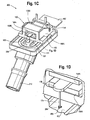
- FIG. 1A An exploded view of a balanced armature transducer or motor assembly 150 is shown in FIG. 1A and an assembled view of the motor assembly is shown in FIG. 1B .
- the balanced armature motor assembly 150 can be used with any earphone ranging from hearing aids to high quality audio listening devices to consumer listening devices.
- FIGS. 1C and 1D the balanced armature motor assembly 150 is shown connected to an exemplary paddle 152 and housing having a nozzle 212.
- the motor assembly 150 generally consists of an armature 156, upper and lower magnets 158A, 158B, a pole piece 160, a bobbin 162, a coil 164, a drive pin 174, and a flex board 167.
- the magnets 158A, 158B can be secured to the pole piece 160 by one or more welds made while the magnets 158A, 158B are held into place by one or more glue dots 182.
- the flex board 167 is a flexible printed circuit board that mounts to the bobbin 162 and the free ends of the wire forming the coil 164 are secured to the flex board 167.
- the armature 156 is generally E-shaped from a top view. In other embodiments, however, the armature 156 may have a U-shape or any other known, suitable shape.
- the armature has a flexible metal reed 166 which extends through the bobbin 162 and coil 164 between the upper and lower magnets 158A, 158B.
- the armature 156 also has two outer legs 168A, 168B, lying generally parallel with each other and interconnected at one end by a connecting part 170. As illustrated in FIG. 1B , the reed 166 is positioned within an air gap 172 formed by the magnets 158A, 158B.
- the two outer armature legs 168A and 168B extend along the outer side along the bobbin 162, coil 164, and pole piece 160.
- the two outer armature legs 168A and 168B are affixed to the pole piece 160.
- the reed 166 can be connected to a paddle 152 with the drive pin 174 at the bulbous or ball-shaped end portion 284 by an adhesive 285.
- the adhesive 285 forms a socket, as depicted in FIG. 1D , around the ball-shaped end portion 284 of the drive pin 174.
- the drive pin 174 can be formed of stainless steel wire or any other known suitable material.
- the electrical input signal is routed to the flex board 167 via a signal cable comprised of two conductors. Each conductor is terminated via a soldered connection to its respective pad on the flex board 167. Each of these pads is electrically connected to a corresponding lead on each end of the coil 164.
- signal current flows through the signal cable and into the coil's 164 windings, magnetic flux is induced into the soft magnetic reed 166 around which the coil 164 is wound.
- the signal current polarity determines the polarity of the magnetic flux induced in the reed 166.
- the free end of the reed 166 is suspended between the two permanent magnets 158A, 158B.
- the magnetic axes of these two permanent magnets 158A, 158B are both aligned perpendicular to the lengthwise axis of the reed 166.
- the lower face of the upper magnet 158A acts as a magnetic south pole while the upper face of the lower magnet 158B acts as a magnetic north pole.
- the free end of the reed 166 oscillates its behavior between that of a magnetic north pole and south pole, respectively.
- the free end of the reed 166 repels from the north-pole face of the lower magnet 158B and attracts to the south-pole face of the upper magnet 158A.
- the free end of the reed 166 oscillates between north and south pole behavior, its physical location in the air gap 172 oscillates in kind, thus mirroring the waveform of the electrical input signal.
- the motion of the reed 166 by itself functions as an extremely inefficient acoustic radiator due to its minimal surface area and lack of an acoustic seal between its front and rear surfaces.
- the drive pin 174 is utilized to couple the mechanical motion of the free end of the reed 166 to an acoustically sealed, lightweight paddle 152 of significantly larger surface area.
- the resulting acoustic volume velocity is then transmitted through the earphone nozzle 212 and ultimately into the user's ear canal, thus completing the transduction of the electrical input signal into the acoustical energy detected by the user.
- FIGS. 2A-2C depict a close-up view of the drive pin 174 secured to the reed 166.
- the drive pin 174 can be secured to the reed 166 by a weld 169 using a drive pin welding machine 200, which is described herein.
- the reed 166 has a first surface 171 and an opposing second surface 173.
- the drive pin 174 generally extends from the first reed surface 171. However, a first end 179 of the drive pin 174 extends generally through the entirety of the reed 166 passing through the first surface 171 and the body of the reed 166 to the second surface 173.
- the drive pin 174 may scarcely protrude through the second surface 173 of the reed 166.
- the first end 179 of the drive pin 174 may be flush with the second surface 173 of the reed 166, or may pass through only a portion of the body of the reed 166 without passing through the second surface 173.
- the drive pin 174 may be formed with a slight bulbous or ball-shaped end portion 284 on the free end of the drive pin 174 (away from the reed 166).
- the ball-shaped end portion 284 of the drive pin 174 has a greater diameter than the middle portion of the drive pin 174.
- the ball shaped end portion 284 is formed when the drive pin 174 is cut to length by a second laser 264B, the cutting process liquefying a portion of the metal end of the drive pin 174 which thereafter cools and solidifies to form the bulbous ball shaped end portion 284, as described herein.
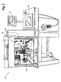
- FIGS. 3-5A depict a drive pin welding machine 200.
- the drive pin welding machine 200 generally comprises a video monitor 210, a control panel 220, and a welding unit 250.
- the welding unit 250 has a first laser 264A for welding the drive pin 174 to the reed 166 and second laser 264B for cutting the feed wire 278 to form the drive pin 174.
- the welding unit 250 has a wire spool 254 having a supply of feed wire 278, which when affixed and cut to length, forms the drive pin 174.
- the welding unit 250 also comprises a parts transfer slide 256, which slides in track 255, for moving the armatures into the welding zone and a parts holding fixture 258 having a plurality of nests 259.
- the welding unit 250 also includes optical viewing equipment, in particular, an optical microscope 260 for determining whether a reed 166 is present in the parts holding fixture 258 and a video camera 262 to create a live image of the reed 166 and drive pin 174 in the welding position and to focus the lasers 264A, 264B.
- optical viewing equipment in particular, an optical microscope 260 for determining whether a reed 166 is present in the parts holding fixture 258 and a video camera 262 to create a live image of the reed 166 and drive pin 174 in the welding position and to focus the lasers 264A, 264B.
- the welding unit 250 can also be outfitted with a door 252, which includes a viewing window 253 for outside observation and viewing purposes.
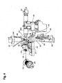
- the welding unit 250 also has a wire guide 266 for properly placing the feed wire 278 on the reed 166, front and back grippers 268, 270 for gripping and selectively advancing the feed wire 278, a main slide 272 and a top slide 274 for advancing the feed wire 278.
- the rear gripper 270 moves with the main slide 272.
- the top slide 274 moves with the main slide 272 and also can move relative to main slide 272 in tracks 279 located on the main slide 272 as depicted in FIG. 6B .
- the wire guide 266 and the front gripper 268 move with the top slide 274.
- the main slide 272 moves in tracks 281 as shown in FIG. 6B .
- the main slide 272 has multiple functions including feeding the drive pin material or feed wire 278, determining the overall travel length of the wire guide 266, and moving the wire guide 266 out of the way from the beam from the second laser 264B during the cutting process.
- the wire guide 266 is integrally formed with a gas distribution fixture 269, which is fed gas from a gas line 267.
- FIG. 5B depicts a cross-sectional view of the gas distribution fixture 269.
- Gas distribution fixture 269 has a port 271 for feeding gas to the wire guide 266, which aids in cooling the weld surfaces.
- the welding unit 250 is configured to attach the first end 179 of the feed wire 278 to the reed 166 using a laser welding process and then cut the feed wire 278 with a laser to form a drive pin 174, as shown in FIG. 1 .
- this process can be accomplished either manually or automatically.
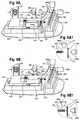
- FIGS. 6A through 6F and FIGS. 6A1-6D1 , and 6F1 The welding process performed by the machine 200 is depicted in a series of steps shown in FIGS. 6A through 6F and FIGS. 6A1-6D1 , and 6F1 .
- FIG. 6A to start the welding process, the main slide 272 and the top slide 274 move forward toward the parts holding fixture 258 with the front gripper 268 in a closed position and the back gripper 270 in an open position.
- the feed wire 278 is thus pulled from the spool 254, which is depicted in FIG. 4 , and guided through the wire guide 266.
- FIG. 6B when the top slide 274 comes in contact with the front stop 276, the wire guide 266 motion is stopped.
- the main slide 272 with the rear gripper 270 in the closed position and the front gripper 268 in the open position will continue to move forward causing the feed wire 278 to be forced up against the reed 166 as shown in FIG. 6B1 .
- the distance between the wire guide 266 and the first reed surface 171 is determined by the position of the front stop screw 276, which can be adjusted.
- the stop screw 276 can adjust the distance between the wire guide 266 and the reed surface between 0.026 to 0.028 in. (0.66 to 0.71 mm) depending on the feed wire 278 material. As shown in FIGS.
- the main slide 272 continues to move forward with the rear gripper 270 in the closed position and the front gripper 268 in the open position causing the reed 166 to put pressure on the feed wire 278, thereby causing it to deflect, resulting in a buckled portion 280 of the feed wire 278.
- the wire guide 266 needs to be as close as possible to the first reed surface 171.
- the feed wire 278 is forced up against the reed 166 producing an axial force on the feed wire 278 causing the wire to bend, which forms the buckled portion 280. During this step, the feed wire 278 will exert a compression force against the first reed surface 171. The compression force is caused by the deflection in the buckled portion 280 of the feed wire 278, which, being resilient, has a tendency to reflex or "snap back" to its straight position.
- the first laser 264A produces a laser beam that is applied to the second reed surface 173 at a welding spot and the laser energy melts and partially liquefies the reed 166 material.
- the center of the feed wire 278 is located in the center of the welding spot.
- the feed wire 278 is directed in the same spot where the reed 166 melting occurs and the axial compression force on the wire causes the feed wire 278 to be fed into molten area to form the weld 169.
- the reflex action of the buckled portion 280 of the feed wire 278 causes the first end 179 of the feed wire 278 to pass through the first surface 171 of the reed 166, and into the temporarily liquefied portion of the body of the reed 166.
- the buckled portion 280 in the feed wire 278 is relieved to form a straight wire as shown in FIG. 6D .
- the feed wire 278 After solidification of the molten area, the feed wire 278 is captured in the reed material, and the result is a robust weld 169 between the reed 166 and the feed wire 278. After the feed wire 278 is captured in the reed 166, the first end 179 of the feed wire 278 will extend through the first surface 171 of the reed, and may protrude slightly from the second surface 173 of the reed 166.
- the pulse duration of the first laser 264A parameters can be set very short to cause the molten reed 166 to become solidified after a short period of time.
- the main slide 272 retracts, with the front gripper 268 in the open position and the back gripper 270 in the open position, causing the top slide 274 and the wire guide 266 to retract. This process ensures that the wire guide 266 is moved out of the way of the second laser 264B beam before firing the second laser 264B beam.
- the second laser 264B emits a laser pulse to cut the feed wire 278 to form the drive pin 174.
- the feed wire 278 is then cut at a predetermined location adjacent to the second laser 264B to form the drive pin 174 by cutting it to a desired length.
- a bulbous or ball-shaped end portion 284 is formed on the second end of the drive pin 174, and a bulbous or ball-shaped portion is also formed on the end of the next portion of the feed wire 278 which forms the first end 179 of the next drive pin 174.
- the ball-shaped end portion 284 is somewhat larger in diameter than the average overall drive pin diameter, on both ends of the drive pin 174.
- the ball-shaped end portion 284 has a larger surface area for contacting adhesive, thus creating a better glue joint connection between the paddle 152 and the drive pin 174. Because the glue forms a socket 285, as depicted in FIG. 1D , around the ball-shaped end portion 284 of the drive pin 174, a stronger "ball and socket" glue joint is formed, that is less susceptible to mechanical hysteresis.
- the parts holding fixture 258 After cutting the feed wire 278 to form the drive pin 174, the parts holding fixture 258 then moves back so that the optical microscope 260 can provide images of the reed 166 position in the parts holding fixture 258 for the next part. If a reed is "found" by the optical microscope 260, the welding sequence discussed above will start over again. If no part is loaded in a particular nest 259, the slide will move to the next part. This operation will continue until parts from all loaded nests 259 have drive pins 174 cut and welded to the reeds 166. After completing welds 169 and cuts for all of the motor assemblies located in nests 259, the parts holding fixture 258 automatically moves to re-loading position, and the door 252 is manually opened. The motor assemblies 150 can then be removed and each of the corresponding ball shaped end portions 284 of the drive pins 174 can be glued to a corresponding paddle 152.
- the drive pin welding machine 200 can be operated in manual mode.
- the operator can move the parts holding fixture 258 by moving the parts transfer slide 256 manually.
- the user moves the parts transfer slide 256 and the parts holding fixture 258 in front of the optical microscope 260.
- the parts transfer slide 256 is stopped and the drive pin welding machine 250 can commence welding the feed wire 278 to the reed 166 and cutting the feed wire 278 to form the pin 174, as described previously herein.
- the optical microscope 260 provides a live picture of the welding operation, which is displayed on the video monitor 210.
- the correct reed position is monitored by the video monitor 210 and may be compared to a coordinate system generated by a cross hair generator.
- inert gas "Argon" can be projected onto the welding surfaces during the welding process. Projecting the inert gas onto the surfaces aids in preventing oxidation, minimizing drive pin 174 heating, and reducing the size of the heat-affected zone on the reed.
- the gas distribution fixture 269 directs the inert gas flow to the welding surfaces.
- the welding parameters must be set properly.
- the laser parameters are defined in a way that only the reed surface in contact with the feed wire 278 is melted and the feed wire 278 is fed into the molten material.
- the laser parameters such as the spot size, peak power, and pulsing width need to be determined as a function of the reed and wire/drive pin materials;
- the drive pin and the reed material must be protected from large amounts of heat, which can be accomplished through inert gas flow, and (3) the laser pulse must be set short, preferably 1 to 2 milliseconds.
- a LaSag laser power supply is used for generating the welding energy used in the described welding and cutting processes.
- the laser beams can be delivered through fiber optics cables to processing heads.
- the processing head can have a lens with a 100mm focal distance.
- the reed 166 welding surface must be placed in the focal point of the lens.
- a lens with a longer focal length has two advantages: (1) it allows for a greater distance for positioning of the reed and (2) it is easier to protect the lens from welding material splattering from the reed.
- easy-to-change glass plates can be used to provide lens protection.
- the laser parameters are selected as a function of the material and the weld joint properties.
- the laser's parameters have a direct effect over the weld joint quality, laser spot size, and laser penetration depth.
- the welding machine sequence can be controlled by a programmable logic controller ("PLC").
- PLC programmable logic controller
- the PLC can be interfaced with the lasers 264A, 264B, with a suitable connector, such as an X51 connector.
- the lasers 264A and 264B can be any type of suitable laser such as a LaSag laser.
- two different welding programs or "recipes" can be used.
- a time sharing dual fiber laser system can be used, where the PLC can switch the laser power supply from the first laser 264A to the second laser 264B. Time sharing between the two fibers allows the lasers to fire separately and independently.
- the PLC is connected to the fibers and according to the desired function instructs the fibers to fire the lasers to cause the welding or cutting operation.
- the PLC performs a program change or "recipe change" to alter the laser parameters such as from welding to cutting.
- the welding function and the cutting function may differ from each other by pulse duration and power intensity. It is also contemplated that the above could be accomplished using separate power sources for the lasers 264A and 264B.
Landscapes
- Engineering & Computer Science (AREA)
- Physics & Mathematics (AREA)
- Acoustics & Sound (AREA)
- Signal Processing (AREA)
- Manufacturing & Machinery (AREA)
- Electromagnetism (AREA)
- Laser Beam Processing (AREA)
- Electrostatic, Electromagnetic, Magneto- Strictive, And Variable-Resistance Transducers (AREA)
- Headphones And Earphones (AREA)
- Wire Processing (AREA)
Applications Claiming Priority (2)
| Application Number | Priority Date | Filing Date | Title |
|---|---|---|---|
| US12/833,639 US8549733B2 (en) | 2010-07-09 | 2010-07-09 | Method of forming a transducer assembly |
| PCT/US2011/042593 WO2012006213A1 (en) | 2010-07-09 | 2011-06-30 | Drive pin forming method and assembly for a transducer |
Publications (2)
| Publication Number | Publication Date |
|---|---|
| EP2591616A1 EP2591616A1 (en) | 2013-05-15 |
| EP2591616B1 true EP2591616B1 (en) | 2014-12-24 |
Family
ID=44533081
Family Applications (1)
| Application Number | Title | Priority Date | Filing Date |
|---|---|---|---|
| EP11749585.3A Not-in-force EP2591616B1 (en) | 2010-07-09 | 2011-06-30 | Drive pin forming method for a balanced armature transducer and balanced armature transducer |
Country Status (9)
| Country | Link |
|---|---|
| US (1) | US8549733B2 (enExample) |
| EP (1) | EP2591616B1 (enExample) |
| JP (2) | JP5927186B2 (enExample) |
| KR (1) | KR101747081B1 (enExample) |
| CN (1) | CN102986253B (enExample) |
| DK (1) | DK2591616T3 (enExample) |
| SG (1) | SG186793A1 (enExample) |
| TW (1) | TWI508575B (enExample) |
| WO (1) | WO2012006213A1 (enExample) |
Families Citing this family (8)
| Publication number | Priority date | Publication date | Assignee | Title |
|---|---|---|---|---|
| US8538061B2 (en) * | 2010-07-09 | 2013-09-17 | Shure Acquisition Holdings, Inc. | Earphone driver and method of manufacture |
| US9326074B2 (en) | 2013-09-24 | 2016-04-26 | Knowles Electronics, Llc | Increased compliance flat reed transducer |
| EP3073758B1 (en) * | 2013-11-19 | 2021-05-19 | Sony Corporation | Headphone and acoustic characteristic adjustment method |
| US9888322B2 (en) | 2014-12-05 | 2018-02-06 | Knowles Electronics, Llc | Receiver with coil wound on a stationary ferromagnetic core |
| KR20160081641A (ko) * | 2014-12-31 | 2016-07-08 | 도시바삼성스토리지테크놀러지코리아 주식회사 | 이어폰 및 이어폰 제작 방법 |
| US10154347B2 (en) * | 2015-10-23 | 2018-12-11 | Bose Corporation | Bushings constrained by compression in levered apparatus |
| JP2021002697A (ja) * | 2017-09-05 | 2021-01-07 | アルプスアルパイン株式会社 | 発音装置 |
| EP3764665B1 (en) * | 2019-07-09 | 2023-06-07 | GN Audio A/S | A method for manufacturing a hearing device |
Family Cites Families (127)
| Publication number | Priority date | Publication date | Assignee | Title |
|---|---|---|---|---|
| US2325590A (en) | 1940-05-11 | 1943-08-03 | Sonotone Corp | Earphone |
| US2430229A (en) | 1943-10-23 | 1947-11-04 | Zenith Radio Corp | Hearing aid earpiece |
| US2521414A (en) | 1947-12-01 | 1950-09-05 | Mayer B A Schier | Adjustable auditory insert |
| US2808468A (en) | 1952-02-07 | 1957-10-01 | Sonotone Corp | Magnetic insert earphone and inserts therefor |
| US2971065A (en) | 1956-10-10 | 1961-02-07 | Sonotone Corp | Ear insert hearing aid |
| US3068954A (en) | 1958-02-10 | 1962-12-18 | Charles W Strzalkowski | Hearing aid apparatus and method |
| US3265819A (en) | 1963-05-15 | 1966-08-09 | Sonotone Corp | Ear insert hearing aid |
| USRE26258E (en) | 1964-04-02 | 1967-08-29 | In-the-ear hearing aid | |
| US3491436A (en) | 1964-08-20 | 1970-01-27 | Industrial Research Prod Inc | Method of connecting drive pin to an armature of an electroacoustic transducer |
| GB1119447A (en) | 1965-03-26 | 1968-07-10 | Danavox Internat A S | Hearing aid |
| US3374318A (en) | 1965-04-01 | 1968-03-19 | Dahlberg Electronics | Wax guard for hearing aids |
| US3312789A (en) | 1966-02-03 | 1967-04-04 | Dahlberg Electronics | Ear canal hearing aid |
| DE1960228A1 (de) * | 1968-12-05 | 1970-08-27 | Semperit Gummiwerk Gmbh Deutsc | Verfahren zum Schneiden von gummiertem Stahlkord |
| JPS507927B1 (enExample) * | 1969-05-29 | 1975-03-31 | ||
| US3777078A (en) * | 1972-01-14 | 1973-12-04 | Bell Canada Northern Electric | Linkage arrangement in pivoting armature transducer |
| JPS507927A (enExample) * | 1973-05-31 | 1975-01-27 | ||
| NL7613904A (en) | 1976-12-15 | 1978-06-19 | Harmen Broersma | Transducer with electromagnetic converter for miniature hearing aid - has chamber with partition partly of foil with hole for push rod and damping |
| US4311206A (en) | 1978-05-15 | 1982-01-19 | Johnson Rubein V | Hearing aid ear mold with improved discrimination |
| JPS54167728U (enExample) * | 1978-05-17 | 1979-11-26 | ||
| JPS55112176A (en) * | 1979-02-19 | 1980-08-29 | Osaka Denki Kk | Method and device for controlling wire feeding |
| DE2923865C2 (de) | 1979-06-13 | 1981-09-17 | Thyssen Edelstahlwerke AG, 4000 Düsseldorf | Verfahren zum Zusammensetzen der Einzelteile eines streufeldarmen Dauermagnetsystems für Lautsprecher |
| US4295066A (en) | 1980-01-11 | 1981-10-13 | Cts Corporation | Electromagnetic actuator |
| US4375016A (en) | 1980-04-28 | 1983-02-22 | Qualitone Hearing Aids Inc. | Vented ear tip for hearing aid and adapter coupler therefore |
| DE3023871A1 (de) | 1980-06-26 | 1982-01-14 | Robert Bosch Gmbh, 7000 Stuttgart | Hoergeraet |
| US4407389A (en) | 1981-01-19 | 1983-10-04 | Johnson Rubein V | Vented acoustic ear mold for hearing aids |
| US4443668A (en) | 1981-03-23 | 1984-04-17 | Warren James C | Earplug mounting device with audio passageway |
| US4420657A (en) | 1981-10-29 | 1983-12-13 | Acs Communications, Inc. | Adjustable headset |
| US4473722B1 (en) | 1982-06-07 | 1995-06-20 | Knowles Electronics Co | Electroacoustic transducers |
| US4592370A (en) | 1982-09-27 | 1986-06-03 | Minnesota Mining And Manufacturing Company | Ear canal electrode for auditory testing |
| US4532649A (en) | 1983-07-03 | 1985-07-30 | Gaspare Bellafiore | Hearing aid |
| US4520236A (en) | 1983-11-30 | 1985-05-28 | Nu-Bar Electronics | Sound transfer from a hearing aid to the human ear drum |
| GB2155276B (en) | 1984-03-02 | 1987-10-21 | Beltone Electronics Corp | Hearing aid ear piece with wax guard |
| AT380762B (de) | 1984-08-06 | 1986-07-10 | Viennatone Gmbh | Hoergeraet |
| IT209301Z2 (it) | 1984-12-15 | 1988-09-20 | Siemens Ag | Protesi uditiva. |
| DE3540579A1 (de) | 1985-11-15 | 1987-05-27 | Toepholm & Westermann | Im-ohr-hoergeraet |
| US4870688A (en) | 1986-05-27 | 1989-09-26 | Barry Voroba | Mass production auditory canal hearing aid |
| US4677408A (en) | 1986-07-28 | 1987-06-30 | G. General Electro-Components, Inc. | Solenoid coil connection |
| DE3723275A1 (de) | 1986-09-25 | 1988-03-31 | Temco Japan | Ohrmikrofon |
| US5002151A (en) | 1986-12-05 | 1991-03-26 | Minnesota Mining And Manufacturing Company | Ear piece having disposable, compressible polymeric foam sleeve |
| US4870689A (en) | 1987-04-13 | 1989-09-26 | Beltone Electronics Corporation | Ear wax barrier for a hearing aid |
| DE8713369U1 (de) | 1987-10-05 | 1989-02-09 | Siemens AG, 1000 Berlin und 8000 München | Vorrichtung zum Verschließen von Öffnungen an Hörgeräten oder Ohrpaßstücken für Hörgeräte |
| US5131128A (en) | 1987-10-14 | 1992-07-21 | Gn Danavox A/S | Protection element for all-in-the-ear hearing aid and tool for use in the replacement hereof |
| US4867267A (en) | 1987-10-14 | 1989-09-19 | Industrial Research Products, Inc. | Hearing aid transducer |
| US4969534A (en) | 1988-08-08 | 1990-11-13 | Minnesota Mining And Manufacturing Company | Hearing aid employing a viscoelastic material to adhere components to the casing |
| JP2546271Y2 (ja) | 1988-12-12 | 1997-08-27 | ソニー株式会社 | 電気音響変換器 |
| US4956868A (en) | 1989-10-26 | 1990-09-11 | Industrial Research Products, Inc. | Magnetically shielded electromagnetic acoustic transducer |
| GB8928899D0 (en) | 1989-12-21 | 1990-02-28 | Knowles Electronics Co | Coil assemblies |
| US5327506A (en) | 1990-04-05 | 1994-07-05 | Stites Iii George M | Voice transmission system and method for high ambient noise conditions |
| US5068901A (en) | 1990-05-01 | 1991-11-26 | Knowles Electronics, Inc. | Dual outlet passage hearing aid transducer |
| US5319163A (en) | 1990-06-07 | 1994-06-07 | Scott Robert T | Waterproof earmold-to-earphone adapter |
| DE69233156T2 (de) | 1991-01-17 | 2004-07-08 | Adelman, Roger A. | Verbessertes hörgerät |
| US5193116A (en) | 1991-09-13 | 1993-03-09 | Knowles Electronics, Inc. | Hearing and output transducer with self contained amplifier |
| US5682020A (en) | 1991-12-09 | 1997-10-28 | Oliveira; Robert J. | Sealing of hearing aid to ear canal |
| US5220612A (en) | 1991-12-20 | 1993-06-15 | Tibbetts Industries, Inc. | Non-occludable transducers for in-the-ear applications |
| US5299176A (en) | 1991-12-20 | 1994-03-29 | Tibbetts Industries, Inc. | Balanced armature transducers with transverse gap |
| US5887070A (en) | 1992-05-08 | 1999-03-23 | Etymotic Research, Inc. | High fidelity insert earphones and methods of making same |
| DK170012B1 (da) | 1992-09-10 | 1995-04-24 | Peer Kuhlmann | Øremikrofon til indsætning i øre i forbindelse med mobiltelefoner og mobilradio |
| US5647013C1 (en) | 1992-10-29 | 2001-05-08 | Knowles Electronics Co | Electroacoustic transducer |
| USD360949S (en) | 1993-09-01 | 1995-08-01 | Knowles Electronics, Inc. | Hearing aid receiver |
| USD360948S (en) | 1993-09-01 | 1995-08-01 | Knowles Electronics, Inc. | Hearing aid receiver |
| USD360691S (en) | 1993-09-01 | 1995-07-25 | Knowles Electronics, Inc. | Hearing aid receiver |
| US5655026A (en) | 1993-12-23 | 1997-08-05 | Otto Engineering, Inc. | Ear receiver |
| US5692059A (en) | 1995-02-24 | 1997-11-25 | Kruger; Frederick M. | Two active element in-the-ear microphone system |
| US5661420A (en) | 1995-03-08 | 1997-08-26 | Etymotic Research, Inc. | Mounting configuration for monolithic integrated circuit |
| US5721783A (en) | 1995-06-07 | 1998-02-24 | Anderson; James C. | Hearing aid with wireless remote processor |
| DE19525865A1 (de) | 1995-07-15 | 1997-01-16 | Sennheiser Electronic | Hörhilfe mit einem elektrodynamischen Schallwandler |
| NL1000880C2 (nl) | 1995-07-24 | 1997-01-28 | Microtronic Nederland Bv | Transducer. |
| NL1000878C2 (nl) | 1995-07-24 | 1997-01-28 | Microtronic Nederland Bv | Transducer. |
| USD377796S (en) | 1995-09-13 | 1997-02-04 | Sony Corporation | Earphone combined with microphone |
| US5753870A (en) | 1995-10-23 | 1998-05-19 | Schlaegel; Norman D. | Continuous flow earmold tubing connector with a filter |
| US5687244A (en) | 1996-03-28 | 1997-11-11 | Stanton Magnetics, Inc. | Bone conduction speaker and mounting system |
| NL1004877C2 (nl) | 1996-12-23 | 1998-08-03 | Microtronic Nederland Bv | Elektroakoestische transducent. |
| US6041131A (en) | 1997-07-09 | 2000-03-21 | Knowles Electronics, Inc. | Shock resistant electroacoustic transducer |
| US6205227B1 (en) | 1998-01-31 | 2001-03-20 | Sarnoff Corporation | Peritympanic hearing instrument |
| US5960093A (en) | 1998-03-30 | 1999-09-28 | Knowles Electronics, Inc. | Miniature transducer |
| DE19821860A1 (de) | 1998-05-15 | 1999-11-18 | Nokia Deutschland Gmbh | Treiber für flaches Klangpaneel |
| US6137889A (en) | 1998-05-27 | 2000-10-24 | Insonus Medical, Inc. | Direct tympanic membrane excitation via vibrationally conductive assembly |
| NL1011733C1 (nl) | 1999-04-06 | 2000-10-09 | Microtronic Nederland Bv | Elektroakoestische transducent met een membraan en werkwijze voor het bevestigen van een membraan in een dergelijke transducent. |
| USD468299S1 (en) | 1999-05-10 | 2003-01-07 | Peter V. Boesen | Communication device |
| US6658134B1 (en) | 1999-08-16 | 2003-12-02 | Sonionmicrotronic Nederland B.V. | Shock improvement for an electroacoustic transducer |
| DK1219135T3 (da) | 1999-10-07 | 2003-10-13 | Knowles Electronics Llc | Transducer, der kan modstå chok |
| DE19954880C1 (de) | 1999-11-15 | 2001-01-25 | Siemens Audiologische Technik | Elektromagnetischer Wandler zur Schallerzeugung in Hörhilfen, insbesondere miniaturisierten elektronischen Hörgeräten |
| US7164776B2 (en) | 2000-01-07 | 2007-01-16 | Knowles Electronics, Llc. | Vibration balanced receiver |
| JP4260333B2 (ja) | 2000-03-16 | 2009-04-30 | スター精密株式会社 | 電気音響変換器 |
| EP1302092A2 (en) | 2000-05-24 | 2003-04-16 | Sonionmicrotronic Nederland B.V. | An assembly comprising an electrical element |
| US7050602B2 (en) | 2000-08-14 | 2006-05-23 | Knowles Electronics Llc. | Low capacitance receiver coil |
| USD453119S1 (en) | 2000-11-14 | 2002-01-29 | Star Micronics Co., Ltd. | Audible signal for alarms |
| US7103196B2 (en) | 2001-03-12 | 2006-09-05 | Knowles Electronics, Llc. | Method for reducing distortion in a receiver |
| JP2002300698A (ja) | 2001-04-02 | 2002-10-11 | Star Micronics Co Ltd | レシーバおよび携帯用通信機器 |
| US7088839B2 (en) | 2001-04-04 | 2006-08-08 | Sonion Nederland B.V. | Acoustic receiver having improved mechanical suspension |
| US6727789B2 (en) * | 2001-06-12 | 2004-04-27 | Tibbetts Industries, Inc. | Magnetic transducers of improved resistance to arbitrary mechanical shock |
| USD468300S1 (en) | 2001-06-26 | 2003-01-07 | Peter V. Boesen | Communication device |
| USD468301S1 (en) | 2001-08-09 | 2003-01-07 | Star Micronics Co., Ltd. | Earphone |
| JP3768431B2 (ja) | 2001-10-31 | 2006-04-19 | スター精密株式会社 | 挿入型イヤホン |
| US7190803B2 (en) | 2002-04-09 | 2007-03-13 | Sonion Nederland Bv | Acoustic transducer having reduced thickness |
| US7206425B2 (en) | 2003-01-23 | 2007-04-17 | Adaptive Technologies, Inc. | Actuator for an active noise control system |
| USD490399S1 (en) | 2003-02-14 | 2004-05-25 | Star Micronics Co., Ltd. | Earphone with microphone |
| DE602004023499D1 (de) | 2003-05-09 | 2009-11-19 | Knowles Electronics Llc | Gerät und verfahren zur erzeugung akustischer energie in einer lautsprecheranordnung |
| US7024010B2 (en) | 2003-05-19 | 2006-04-04 | Adaptive Technologies, Inc. | Electronic earplug for monitoring and reducing wideband noise at the tympanic membrane |
| US7321664B2 (en) | 2004-01-13 | 2008-01-22 | Sonionmicrotronic Nederland B.V. | Receiver having an improved bobbin |
| JP2005278015A (ja) | 2004-03-26 | 2005-10-06 | Star Micronics Co Ltd | イヤホン |
| US7362878B2 (en) | 2004-06-14 | 2008-04-22 | Knowles Electronics, Llc. | Magnetic assembly for a transducer |
| US7242788B2 (en) | 2004-08-16 | 2007-07-10 | Hpv Technologies, Llc | Securing magnets in high-efficiency planar magnetic transducers |
| US7317806B2 (en) | 2004-12-22 | 2008-01-08 | Ultimate Ears, Llc | Sound tube tuned multi-driver earpiece |
| US7263195B2 (en) | 2004-12-22 | 2007-08-28 | Ultimate Ears, Llc | In-ear monitor with shaped dual bore |
| US7194103B2 (en) | 2004-12-22 | 2007-03-20 | Ultimate Ears, Llc | In-ear monitor with hybrid diaphragm and armature design |
| US7194102B2 (en) | 2004-12-22 | 2007-03-20 | Ultimate Ears, Llc | In-ear monitor with hybrid dual diaphragm and single armature design |
| US7529379B2 (en) | 2005-01-04 | 2009-05-05 | Motorola, Inc. | System and method for determining an in-ear acoustic response for confirming the identity of a user |
| DE602006020645D1 (de) | 2005-01-10 | 2011-04-28 | Sonion Nederland Bv | Montage eines elektroakustischen Wandlers in Schalen von persönlichen Kommunikationsgeräten |
| WO2006105268A2 (en) | 2005-03-28 | 2006-10-05 | Knowles Electronics, Llc | Acoustic assembly for a transducer |
| JP4676285B2 (ja) * | 2005-08-30 | 2011-04-27 | セイコーインスツル株式会社 | 表面実装型圧電振動子とその製造方法、発振器、電子機器及び電波時計 |
| US7489794B2 (en) | 2005-09-07 | 2009-02-10 | Ultimate Ears, Llc | Earpiece with acoustic vent for driver response optimization |
| US20070104340A1 (en) | 2005-09-28 | 2007-05-10 | Knowles Electronics, Llc | System and Method for Manufacturing a Transducer Module |
| EP1980134A4 (en) | 2006-01-30 | 2011-03-23 | Etymotic Res Inc | BUTTON HEADER USING A MOBILE COIL ATTACK DEVICE |
| US8031900B2 (en) | 2006-02-27 | 2011-10-04 | Logitech International, S.A. | Earphone ambient eartip |
| US8208674B2 (en) | 2006-05-23 | 2012-06-26 | Rh Lyon Corp | Squeeze-stretch driver for earphone and the like |
| US8170249B2 (en) | 2006-06-19 | 2012-05-01 | Sonion Nederland B.V. | Hearing aid having two receivers each amplifying a different frequency range |
| USD567217S1 (en) | 2006-08-18 | 2008-04-22 | Star Micronics Co., Ltd. | Earphone |
| US7577269B2 (en) * | 2006-08-28 | 2009-08-18 | Technology Properties Limited | Acoustic transducer |
| US8194911B2 (en) | 2007-03-27 | 2012-06-05 | Logitech International, S.A. | Earphone integrated eartip |
| CN101785327B (zh) | 2007-07-23 | 2013-11-20 | 艾瑟斯技术有限责任公司 | 折声学声音转换连接耦合器和耳塞 |
| US8135163B2 (en) | 2007-08-30 | 2012-03-13 | Klipsch Group, Inc. | Balanced armature with acoustic low pass filter |
| DE102008049932A1 (de) | 2007-10-02 | 2009-05-28 | Phitek Systems Ltd. | Bauteil für Kopfhörer mit Geräuschunterdrückung |
| US8447059B2 (en) | 2007-10-31 | 2013-05-21 | Thx Ltd | Earphone device |
| WO2009075834A1 (en) | 2007-12-10 | 2009-06-18 | Klipsch, Llc | In-ear headphones |
| EP2101512B1 (en) | 2008-03-12 | 2012-07-18 | AKG Acoustics GmbH | In-ear earphone with multiple transducers |
| JP5411542B2 (ja) * | 2008-10-27 | 2014-02-12 | 和仁 鬼頭 | 溶接装置 |
-
2010
- 2010-07-09 US US12/833,639 patent/US8549733B2/en active Active
-
2011
- 2011-06-30 DK DK11749585.3T patent/DK2591616T3/en active
- 2011-06-30 KR KR1020137003347A patent/KR101747081B1/ko not_active Expired - Fee Related
- 2011-06-30 EP EP11749585.3A patent/EP2591616B1/en not_active Not-in-force
- 2011-06-30 SG SG2012094512A patent/SG186793A1/en unknown
- 2011-06-30 JP JP2013518709A patent/JP5927186B2/ja not_active Expired - Fee Related
- 2011-06-30 WO PCT/US2011/042593 patent/WO2012006213A1/en not_active Ceased
- 2011-06-30 CN CN201180033857.8A patent/CN102986253B/zh active Active
- 2011-07-08 TW TW100124319A patent/TWI508575B/zh not_active IP Right Cessation
-
2015
- 2015-12-09 JP JP2015240018A patent/JP6263520B2/ja not_active Expired - Fee Related
Also Published As
| Publication number | Publication date |
|---|---|
| US20120008804A1 (en) | 2012-01-12 |
| WO2012006213A1 (en) | 2012-01-12 |
| CN102986253B (zh) | 2017-08-15 |
| EP2591616A1 (en) | 2013-05-15 |
| KR20130036759A (ko) | 2013-04-12 |
| JP6263520B2 (ja) | 2018-01-17 |
| JP2016076980A (ja) | 2016-05-12 |
| DK2591616T3 (en) | 2015-01-26 |
| SG186793A1 (en) | 2013-02-28 |
| JP2013530656A (ja) | 2013-07-25 |
| JP5927186B2 (ja) | 2016-06-01 |
| CN102986253A (zh) | 2013-03-20 |
| TWI508575B (zh) | 2015-11-11 |
| TW201230826A (en) | 2012-07-16 |
| KR101747081B1 (ko) | 2017-06-27 |
| US8549733B2 (en) | 2013-10-08 |
Similar Documents
| Publication | Publication Date | Title |
|---|---|---|
| EP2591616B1 (en) | Drive pin forming method for a balanced armature transducer and balanced armature transducer | |
| EP2591611B1 (en) | Earphone driver and method of manufacture | |
| KR101829419B1 (ko) | 이어폰 조립체 | |
| JP2001313989A (ja) | 骨導振動子及びこれを利用した骨導スピーカヘッドセット | |
| JP6883216B2 (ja) | 音響変換装置及び音声出力機器 | |
| HK1178728A (en) | Drive pin forming method and assembly for a transducer | |
| KR101249487B1 (ko) | 아마츄어타입 유닛 생산 시 핀 용접 방법 및 장치 | |
| JP2670076B2 (ja) | アーク放電を用いた情報伝達装置 | |
| JP2004187235A (ja) | スピーカ装置 | |
| JP2005086795A (ja) | 骨導スピーカユニット | |
| JPS5896494A (ja) | スピ−カ−の組立て方法 | |
| HK1178727B (en) | Earphone assembly | |
| CN101715161A (zh) | 驱动单元制造方法和驱动单元 | |
| HK1178727A (en) | Earphone assembly | |
| JP2001231095A (ja) | 発音体 |
Legal Events
| Date | Code | Title | Description |
|---|---|---|---|
| PUAI | Public reference made under article 153(3) epc to a published international application that has entered the european phase |
Free format text: ORIGINAL CODE: 0009012 |
|
| 17P | Request for examination filed |
Effective date: 20121128 |
|
| AK | Designated contracting states |
Kind code of ref document: A1 Designated state(s): AL AT BE BG CH CY CZ DE DK EE ES FI FR GB GR HR HU IE IS IT LI LT LU LV MC MK MT NL NO PL PT RO RS SE SI SK SM TR |
|
| DAX | Request for extension of the european patent (deleted) | ||
| GRAP | Despatch of communication of intention to grant a patent |
Free format text: ORIGINAL CODE: EPIDOSNIGR1 |
|
| INTG | Intention to grant announced |
Effective date: 20140210 |
|
| GRAP | Despatch of communication of intention to grant a patent |
Free format text: ORIGINAL CODE: EPIDOSNIGR1 |
|
| INTG | Intention to grant announced |
Effective date: 20140820 |
|
| GRAS | Grant fee paid |
Free format text: ORIGINAL CODE: EPIDOSNIGR3 |
|
| GRAA | (expected) grant |
Free format text: ORIGINAL CODE: 0009210 |
|
| AK | Designated contracting states |
Kind code of ref document: B1 Designated state(s): AL AT BE BG CH CY CZ DE DK EE ES FI FR GB GR HR HU IE IS IT LI LT LU LV MC MK MT NL NO PL PT RO RS SE SI SK SM TR |
|
| REG | Reference to a national code |
Ref country code: GB Ref legal event code: FG4D |
|
| REG | Reference to a national code |
Ref country code: CH Ref legal event code: EP |
|
| REG | Reference to a national code |
Ref country code: IE Ref legal event code: FG4D |
|
| REG | Reference to a national code |
Ref country code: AT Ref legal event code: REF Ref document number: 703658 Country of ref document: AT Kind code of ref document: T Effective date: 20150115 |
|
| REG | Reference to a national code |
Ref country code: DK Ref legal event code: T3 Effective date: 20150120 |
|
| REG | Reference to a national code |
Ref country code: DE Ref legal event code: R096 Ref document number: 602011012557 Country of ref document: DE Effective date: 20150212 |
|
| REG | Reference to a national code |
Ref country code: NL Ref legal event code: VDEP Effective date: 20141224 |
|
| PG25 | Lapsed in a contracting state [announced via postgrant information from national office to epo] |
Ref country code: LT Free format text: LAPSE BECAUSE OF FAILURE TO SUBMIT A TRANSLATION OF THE DESCRIPTION OR TO PAY THE FEE WITHIN THE PRESCRIBED TIME-LIMIT Effective date: 20141224 Ref country code: FI Free format text: LAPSE BECAUSE OF FAILURE TO SUBMIT A TRANSLATION OF THE DESCRIPTION OR TO PAY THE FEE WITHIN THE PRESCRIBED TIME-LIMIT Effective date: 20141224 Ref country code: NO Free format text: LAPSE BECAUSE OF FAILURE TO SUBMIT A TRANSLATION OF THE DESCRIPTION OR TO PAY THE FEE WITHIN THE PRESCRIBED TIME-LIMIT Effective date: 20150324 |
|
| REG | Reference to a national code |
Ref country code: LT Ref legal event code: MG4D |
|
| PG25 | Lapsed in a contracting state [announced via postgrant information from national office to epo] |
Ref country code: GR Free format text: LAPSE BECAUSE OF FAILURE TO SUBMIT A TRANSLATION OF THE DESCRIPTION OR TO PAY THE FEE WITHIN THE PRESCRIBED TIME-LIMIT Effective date: 20150325 Ref country code: SE Free format text: LAPSE BECAUSE OF FAILURE TO SUBMIT A TRANSLATION OF THE DESCRIPTION OR TO PAY THE FEE WITHIN THE PRESCRIBED TIME-LIMIT Effective date: 20141224 Ref country code: HR Free format text: LAPSE BECAUSE OF FAILURE TO SUBMIT A TRANSLATION OF THE DESCRIPTION OR TO PAY THE FEE WITHIN THE PRESCRIBED TIME-LIMIT Effective date: 20141224 Ref country code: LV Free format text: LAPSE BECAUSE OF FAILURE TO SUBMIT A TRANSLATION OF THE DESCRIPTION OR TO PAY THE FEE WITHIN THE PRESCRIBED TIME-LIMIT Effective date: 20141224 Ref country code: RS Free format text: LAPSE BECAUSE OF FAILURE TO SUBMIT A TRANSLATION OF THE DESCRIPTION OR TO PAY THE FEE WITHIN THE PRESCRIBED TIME-LIMIT Effective date: 20141224 |
|
| PG25 | Lapsed in a contracting state [announced via postgrant information from national office to epo] |
Ref country code: NL Free format text: LAPSE BECAUSE OF FAILURE TO SUBMIT A TRANSLATION OF THE DESCRIPTION OR TO PAY THE FEE WITHIN THE PRESCRIBED TIME-LIMIT Effective date: 20141224 |
|
| PG25 | Lapsed in a contracting state [announced via postgrant information from national office to epo] |
Ref country code: RO Free format text: LAPSE BECAUSE OF FAILURE TO SUBMIT A TRANSLATION OF THE DESCRIPTION OR TO PAY THE FEE WITHIN THE PRESCRIBED TIME-LIMIT Effective date: 20141224 Ref country code: CZ Free format text: LAPSE BECAUSE OF FAILURE TO SUBMIT A TRANSLATION OF THE DESCRIPTION OR TO PAY THE FEE WITHIN THE PRESCRIBED TIME-LIMIT Effective date: 20141224 Ref country code: SK Free format text: LAPSE BECAUSE OF FAILURE TO SUBMIT A TRANSLATION OF THE DESCRIPTION OR TO PAY THE FEE WITHIN THE PRESCRIBED TIME-LIMIT Effective date: 20141224 Ref country code: ES Free format text: LAPSE BECAUSE OF FAILURE TO SUBMIT A TRANSLATION OF THE DESCRIPTION OR TO PAY THE FEE WITHIN THE PRESCRIBED TIME-LIMIT Effective date: 20141224 Ref country code: EE Free format text: LAPSE BECAUSE OF FAILURE TO SUBMIT A TRANSLATION OF THE DESCRIPTION OR TO PAY THE FEE WITHIN THE PRESCRIBED TIME-LIMIT Effective date: 20141224 |
|
| PG25 | Lapsed in a contracting state [announced via postgrant information from national office to epo] |
Ref country code: IS Free format text: LAPSE BECAUSE OF FAILURE TO SUBMIT A TRANSLATION OF THE DESCRIPTION OR TO PAY THE FEE WITHIN THE PRESCRIBED TIME-LIMIT Effective date: 20150424 Ref country code: PL Free format text: LAPSE BECAUSE OF FAILURE TO SUBMIT A TRANSLATION OF THE DESCRIPTION OR TO PAY THE FEE WITHIN THE PRESCRIBED TIME-LIMIT Effective date: 20141224 |
|
| REG | Reference to a national code |
Ref country code: DE Ref legal event code: R097 Ref document number: 602011012557 Country of ref document: DE |
|
| PLBE | No opposition filed within time limit |
Free format text: ORIGINAL CODE: 0009261 |
|
| STAA | Information on the status of an ep patent application or granted ep patent |
Free format text: STATUS: NO OPPOSITION FILED WITHIN TIME LIMIT |
|
| 26N | No opposition filed |
Effective date: 20150925 |
|
| PG25 | Lapsed in a contracting state [announced via postgrant information from national office to epo] |
Ref country code: IT Free format text: LAPSE BECAUSE OF FAILURE TO SUBMIT A TRANSLATION OF THE DESCRIPTION OR TO PAY THE FEE WITHIN THE PRESCRIBED TIME-LIMIT Effective date: 20141224 |
|
| PG25 | Lapsed in a contracting state [announced via postgrant information from national office to epo] |
Ref country code: MC Free format text: LAPSE BECAUSE OF FAILURE TO SUBMIT A TRANSLATION OF THE DESCRIPTION OR TO PAY THE FEE WITHIN THE PRESCRIBED TIME-LIMIT Effective date: 20141224 |
|
| REG | Reference to a national code |
Ref country code: CH Ref legal event code: PL |
|
| PG25 | Lapsed in a contracting state [announced via postgrant information from national office to epo] |
Ref country code: SI Free format text: LAPSE BECAUSE OF FAILURE TO SUBMIT A TRANSLATION OF THE DESCRIPTION OR TO PAY THE FEE WITHIN THE PRESCRIBED TIME-LIMIT Effective date: 20141224 Ref country code: LU Free format text: LAPSE BECAUSE OF FAILURE TO SUBMIT A TRANSLATION OF THE DESCRIPTION OR TO PAY THE FEE WITHIN THE PRESCRIBED TIME-LIMIT Effective date: 20150630 |
|
| REG | Reference to a national code |
Ref country code: IE Ref legal event code: MM4A |
|
| REG | Reference to a national code |
Ref country code: FR Ref legal event code: ST Effective date: 20160229 |
|
| REG | Reference to a national code |
Ref country code: AT Ref legal event code: UEP Ref document number: 703658 Country of ref document: AT Kind code of ref document: T Effective date: 20141224 |
|
| PG25 | Lapsed in a contracting state [announced via postgrant information from national office to epo] |
Ref country code: IE Free format text: LAPSE BECAUSE OF NON-PAYMENT OF DUE FEES Effective date: 20150630 Ref country code: LI Free format text: LAPSE BECAUSE OF NON-PAYMENT OF DUE FEES Effective date: 20150630 Ref country code: CH Free format text: LAPSE BECAUSE OF NON-PAYMENT OF DUE FEES Effective date: 20150630 |
|
| PG25 | Lapsed in a contracting state [announced via postgrant information from national office to epo] |
Ref country code: FR Free format text: LAPSE BECAUSE OF NON-PAYMENT OF DUE FEES Effective date: 20150630 Ref country code: BE Free format text: LAPSE BECAUSE OF FAILURE TO SUBMIT A TRANSLATION OF THE DESCRIPTION OR TO PAY THE FEE WITHIN THE PRESCRIBED TIME-LIMIT Effective date: 20141224 |
|
| PG25 | Lapsed in a contracting state [announced via postgrant information from national office to epo] |
Ref country code: MT Free format text: LAPSE BECAUSE OF FAILURE TO SUBMIT A TRANSLATION OF THE DESCRIPTION OR TO PAY THE FEE WITHIN THE PRESCRIBED TIME-LIMIT Effective date: 20141224 |
|
| PG25 | Lapsed in a contracting state [announced via postgrant information from national office to epo] |
Ref country code: SM Free format text: LAPSE BECAUSE OF FAILURE TO SUBMIT A TRANSLATION OF THE DESCRIPTION OR TO PAY THE FEE WITHIN THE PRESCRIBED TIME-LIMIT Effective date: 20141224 Ref country code: HU Free format text: LAPSE BECAUSE OF FAILURE TO SUBMIT A TRANSLATION OF THE DESCRIPTION OR TO PAY THE FEE WITHIN THE PRESCRIBED TIME-LIMIT; INVALID AB INITIO Effective date: 20110630 Ref country code: BG Free format text: LAPSE BECAUSE OF FAILURE TO SUBMIT A TRANSLATION OF THE DESCRIPTION OR TO PAY THE FEE WITHIN THE PRESCRIBED TIME-LIMIT Effective date: 20141224 |
|
| PG25 | Lapsed in a contracting state [announced via postgrant information from national office to epo] |
Ref country code: CY Free format text: LAPSE BECAUSE OF FAILURE TO SUBMIT A TRANSLATION OF THE DESCRIPTION OR TO PAY THE FEE WITHIN THE PRESCRIBED TIME-LIMIT Effective date: 20141224 |
|
| PGFP | Annual fee paid to national office [announced via postgrant information from national office to epo] |
Ref country code: DK Payment date: 20170626 Year of fee payment: 7 Ref country code: GB Payment date: 20170627 Year of fee payment: 7 |
|
| PG25 | Lapsed in a contracting state [announced via postgrant information from national office to epo] |
Ref country code: TR Free format text: LAPSE BECAUSE OF FAILURE TO SUBMIT A TRANSLATION OF THE DESCRIPTION OR TO PAY THE FEE WITHIN THE PRESCRIBED TIME-LIMIT Effective date: 20141224 |
|
| PGFP | Annual fee paid to national office [announced via postgrant information from national office to epo] |
Ref country code: AT Payment date: 20170601 Year of fee payment: 7 |
|
| PGFP | Annual fee paid to national office [announced via postgrant information from national office to epo] |
Ref country code: DE Payment date: 20170628 Year of fee payment: 7 |
|
| PG25 | Lapsed in a contracting state [announced via postgrant information from national office to epo] |
Ref country code: MK Free format text: LAPSE BECAUSE OF FAILURE TO SUBMIT A TRANSLATION OF THE DESCRIPTION OR TO PAY THE FEE WITHIN THE PRESCRIBED TIME-LIMIT Effective date: 20141224 |
|
| PG25 | Lapsed in a contracting state [announced via postgrant information from national office to epo] |
Ref country code: PT Free format text: LAPSE BECAUSE OF FAILURE TO SUBMIT A TRANSLATION OF THE DESCRIPTION OR TO PAY THE FEE WITHIN THE PRESCRIBED TIME-LIMIT Effective date: 20141224 |
|
| PG25 | Lapsed in a contracting state [announced via postgrant information from national office to epo] |
Ref country code: AL Free format text: LAPSE BECAUSE OF FAILURE TO SUBMIT A TRANSLATION OF THE DESCRIPTION OR TO PAY THE FEE WITHIN THE PRESCRIBED TIME-LIMIT Effective date: 20141224 |
|
| REG | Reference to a national code |
Ref country code: DE Ref legal event code: R119 Ref document number: 602011012557 Country of ref document: DE |
|
| REG | Reference to a national code |
Ref country code: DK Ref legal event code: EBP Effective date: 20180630 |
|
| REG | Reference to a national code |
Ref country code: AT Ref legal event code: MM01 Ref document number: 703658 Country of ref document: AT Kind code of ref document: T Effective date: 20180630 |
|
| GBPC | Gb: european patent ceased through non-payment of renewal fee |
Effective date: 20180630 |
|
| PG25 | Lapsed in a contracting state [announced via postgrant information from national office to epo] |
Ref country code: GB Free format text: LAPSE BECAUSE OF NON-PAYMENT OF DUE FEES Effective date: 20180630 Ref country code: AT Free format text: LAPSE BECAUSE OF NON-PAYMENT OF DUE FEES Effective date: 20180630 Ref country code: DE Free format text: LAPSE BECAUSE OF NON-PAYMENT OF DUE FEES Effective date: 20190101 |
|
| PG25 | Lapsed in a contracting state [announced via postgrant information from national office to epo] |
Ref country code: DK Free format text: LAPSE BECAUSE OF NON-PAYMENT OF DUE FEES Effective date: 20180630 |