EP3764665B1 - A method for manufacturing a hearing device - Google Patents
A method for manufacturing a hearing device Download PDFInfo
- Publication number
- EP3764665B1 EP3764665B1 EP19185230.0A EP19185230A EP3764665B1 EP 3764665 B1 EP3764665 B1 EP 3764665B1 EP 19185230 A EP19185230 A EP 19185230A EP 3764665 B1 EP3764665 B1 EP 3764665B1
- Authority
- EP
- European Patent Office
- Prior art keywords
- laser light
- chamber
- hearing device
- sound channel
- speaker
- Prior art date
- Legal status (The legal status is an assumption and is not a legal conclusion. Google has not performed a legal analysis and makes no representation as to the accuracy of the status listed.)
- Active
Links
- 238000000034 method Methods 0.000 title claims description 40
- 238000004519 manufacturing process Methods 0.000 title claims description 19
- 239000012815 thermoplastic material Substances 0.000 claims description 28
- 239000000463 material Substances 0.000 claims description 26
- 239000007787 solid Substances 0.000 claims description 25
- 239000007788 liquid Substances 0.000 claims description 24
- 238000007789 sealing Methods 0.000 claims description 22
- 239000003292 glue Substances 0.000 claims description 17
- 238000002844 melting Methods 0.000 claims description 14
- 230000008018 melting Effects 0.000 claims description 14
- 230000008859 change Effects 0.000 claims description 13
- 229920001169 thermoplastic Polymers 0.000 claims description 10
- 239000004416 thermosoftening plastic Substances 0.000 claims description 10
- 239000000853 adhesive Substances 0.000 claims description 9
- 230000001070 adhesive effect Effects 0.000 claims description 9
- 238000001816 cooling Methods 0.000 claims description 6
- 239000012943 hotmelt Substances 0.000 claims description 4
- 239000012774 insulation material Substances 0.000 claims description 3
- 239000004831 Hot glue Substances 0.000 claims description 2
- 238000003466 welding Methods 0.000 description 16
- 230000008569 process Effects 0.000 description 7
- 239000003086 colorant Substances 0.000 description 6
- 230000008901 benefit Effects 0.000 description 5
- 238000009413 insulation Methods 0.000 description 5
- 239000012528 membrane Substances 0.000 description 5
- 239000011248 coating agent Substances 0.000 description 4
- 238000000576 coating method Methods 0.000 description 4
- 230000003993 interaction Effects 0.000 description 4
- 230000000694 effects Effects 0.000 description 3
- 239000006260 foam Substances 0.000 description 3
- 238000010438 heat treatment Methods 0.000 description 3
- 239000004033 plastic Substances 0.000 description 3
- 230000005236 sound signal Effects 0.000 description 3
- 239000002390 adhesive tape Substances 0.000 description 2
- 230000009286 beneficial effect Effects 0.000 description 2
- 230000015572 biosynthetic process Effects 0.000 description 2
- 238000001723 curing Methods 0.000 description 2
- 239000000155 melt Substances 0.000 description 2
- 230000010355 oscillation Effects 0.000 description 2
- 229920001296 polysiloxane Polymers 0.000 description 2
- 238000003860 storage Methods 0.000 description 2
- 239000000126 substance Substances 0.000 description 2
- 239000004838 Heat curing adhesive Substances 0.000 description 1
- XUIMIQQOPSSXEZ-UHFFFAOYSA-N Silicon Chemical compound [Si] XUIMIQQOPSSXEZ-UHFFFAOYSA-N 0.000 description 1
- 230000004913 activation Effects 0.000 description 1
- 230000003321 amplification Effects 0.000 description 1
- 230000000712 assembly Effects 0.000 description 1
- 238000000429 assembly Methods 0.000 description 1
- 230000000903 blocking effect Effects 0.000 description 1
- 230000003203 everyday effect Effects 0.000 description 1
- 239000010808 liquid waste Substances 0.000 description 1
- 230000004048 modification Effects 0.000 description 1
- 238000012986 modification Methods 0.000 description 1
- 238000003199 nucleic acid amplification method Methods 0.000 description 1
- 239000006223 plastic coating Substances 0.000 description 1
- 230000008439 repair process Effects 0.000 description 1
- 238000000926 separation method Methods 0.000 description 1
- 238000007493 shaping process Methods 0.000 description 1
- 230000035939 shock Effects 0.000 description 1
- 229910052710 silicon Inorganic materials 0.000 description 1
- 239000010703 silicon Substances 0.000 description 1
- 230000008685 targeting Effects 0.000 description 1
- 230000009466 transformation Effects 0.000 description 1
Images


Classifications
-
- H—ELECTRICITY
- H04—ELECTRIC COMMUNICATION TECHNIQUE
- H04R—LOUDSPEAKERS, MICROPHONES, GRAMOPHONE PICK-UPS OR LIKE ACOUSTIC ELECTROMECHANICAL TRANSDUCERS; DEAF-AID SETS; PUBLIC ADDRESS SYSTEMS
- H04R31/00—Apparatus or processes specially adapted for the manufacture of transducers or diaphragms therefor
-
- B—PERFORMING OPERATIONS; TRANSPORTING
- B29—WORKING OF PLASTICS; WORKING OF SUBSTANCES IN A PLASTIC STATE IN GENERAL
- B29C—SHAPING OR JOINING OF PLASTICS; SHAPING OF MATERIAL IN A PLASTIC STATE, NOT OTHERWISE PROVIDED FOR; AFTER-TREATMENT OF THE SHAPED PRODUCTS, e.g. REPAIRING
- B29C65/00—Joining or sealing of preformed parts, e.g. welding of plastics materials; Apparatus therefor
- B29C65/02—Joining or sealing of preformed parts, e.g. welding of plastics materials; Apparatus therefor by heating, with or without pressure
- B29C65/14—Joining or sealing of preformed parts, e.g. welding of plastics materials; Apparatus therefor by heating, with or without pressure using wave energy, i.e. electromagnetic radiation, or particle radiation
- B29C65/16—Laser beams
- B29C65/1629—Laser beams characterised by the way of heating the interface
- B29C65/1635—Laser beams characterised by the way of heating the interface at least passing through one of the parts to be joined, i.e. laser transmission welding
-
- B—PERFORMING OPERATIONS; TRANSPORTING
- B29—WORKING OF PLASTICS; WORKING OF SUBSTANCES IN A PLASTIC STATE IN GENERAL
- B29C—SHAPING OR JOINING OF PLASTICS; SHAPING OF MATERIAL IN A PLASTIC STATE, NOT OTHERWISE PROVIDED FOR; AFTER-TREATMENT OF THE SHAPED PRODUCTS, e.g. REPAIRING
- B29C44/00—Shaping by internal pressure generated in the material, e.g. swelling or foaming ; Producing porous or cellular expanded plastics articles
- B29C44/02—Shaping by internal pressure generated in the material, e.g. swelling or foaming ; Producing porous or cellular expanded plastics articles for articles of definite length, i.e. discrete articles
- B29C44/12—Incorporating or moulding on preformed parts, e.g. inserts or reinforcements
- B29C44/18—Filling preformed cavities
- B29C44/188—Sealing off parts of the cavities
-
- B—PERFORMING OPERATIONS; TRANSPORTING
- B29—WORKING OF PLASTICS; WORKING OF SUBSTANCES IN A PLASTIC STATE IN GENERAL
- B29C—SHAPING OR JOINING OF PLASTICS; SHAPING OF MATERIAL IN A PLASTIC STATE, NOT OTHERWISE PROVIDED FOR; AFTER-TREATMENT OF THE SHAPED PRODUCTS, e.g. REPAIRING
- B29C44/00—Shaping by internal pressure generated in the material, e.g. swelling or foaming ; Producing porous or cellular expanded plastics articles
- B29C44/34—Auxiliary operations
- B29C44/3415—Heating or cooling
- B29C44/3419—Quick cooling
-
- B—PERFORMING OPERATIONS; TRANSPORTING
- B29—WORKING OF PLASTICS; WORKING OF SUBSTANCES IN A PLASTIC STATE IN GENERAL
- B29C—SHAPING OR JOINING OF PLASTICS; SHAPING OF MATERIAL IN A PLASTIC STATE, NOT OTHERWISE PROVIDED FOR; AFTER-TREATMENT OF THE SHAPED PRODUCTS, e.g. REPAIRING
- B29C44/00—Shaping by internal pressure generated in the material, e.g. swelling or foaming ; Producing porous or cellular expanded plastics articles
- B29C44/34—Auxiliary operations
- B29C44/3492—Expanding without a foaming agent
-
- B—PERFORMING OPERATIONS; TRANSPORTING
- B29—WORKING OF PLASTICS; WORKING OF SUBSTANCES IN A PLASTIC STATE IN GENERAL
- B29C—SHAPING OR JOINING OF PLASTICS; SHAPING OF MATERIAL IN A PLASTIC STATE, NOT OTHERWISE PROVIDED FOR; AFTER-TREATMENT OF THE SHAPED PRODUCTS, e.g. REPAIRING
- B29C65/00—Joining or sealing of preformed parts, e.g. welding of plastics materials; Apparatus therefor
- B29C65/48—Joining or sealing of preformed parts, e.g. welding of plastics materials; Apparatus therefor using adhesives, i.e. using supplementary joining material; solvent bonding
- B29C65/4805—Joining or sealing of preformed parts, e.g. welding of plastics materials; Apparatus therefor using adhesives, i.e. using supplementary joining material; solvent bonding characterised by the type of adhesives
- B29C65/481—Non-reactive adhesives, e.g. physically hardening adhesives
- B29C65/4815—Hot melt adhesives, e.g. thermoplastic adhesives
-
- H—ELECTRICITY
- H04—ELECTRIC COMMUNICATION TECHNIQUE
- H04R—LOUDSPEAKERS, MICROPHONES, GRAMOPHONE PICK-UPS OR LIKE ACOUSTIC ELECTROMECHANICAL TRANSDUCERS; DEAF-AID SETS; PUBLIC ADDRESS SYSTEMS
- H04R1/00—Details of transducers, loudspeakers or microphones
- H04R1/08—Mouthpieces; Microphones; Attachments therefor
-
- H—ELECTRICITY
- H04—ELECTRIC COMMUNICATION TECHNIQUE
- H04R—LOUDSPEAKERS, MICROPHONES, GRAMOPHONE PICK-UPS OR LIKE ACOUSTIC ELECTROMECHANICAL TRANSDUCERS; DEAF-AID SETS; PUBLIC ADDRESS SYSTEMS
- H04R1/00—Details of transducers, loudspeakers or microphones
- H04R1/10—Earpieces; Attachments therefor ; Earphones; Monophonic headphones
- H04R1/1058—Manufacture or assembly
- H04R1/1075—Mountings of transducers in earphones or headphones
-
- H—ELECTRICITY
- H04—ELECTRIC COMMUNICATION TECHNIQUE
- H04R—LOUDSPEAKERS, MICROPHONES, GRAMOPHONE PICK-UPS OR LIKE ACOUSTIC ELECTROMECHANICAL TRANSDUCERS; DEAF-AID SETS; PUBLIC ADDRESS SYSTEMS
- H04R25/00—Deaf-aid sets, i.e. electro-acoustic or electro-mechanical hearing aids; Electric tinnitus maskers providing an auditory perception
- H04R25/60—Mounting or interconnection of hearing aid parts, e.g. inside tips, housings or to ossicles
- H04R25/604—Mounting or interconnection of hearing aid parts, e.g. inside tips, housings or to ossicles of acoustic or vibrational transducers
-
- B—PERFORMING OPERATIONS; TRANSPORTING
- B29—WORKING OF PLASTICS; WORKING OF SUBSTANCES IN A PLASTIC STATE IN GENERAL
- B29K—INDEXING SCHEME ASSOCIATED WITH SUBCLASSES B29B, B29C OR B29D, RELATING TO MOULDING MATERIALS OR TO MATERIALS FOR MOULDS, REINFORCEMENTS, FILLERS OR PREFORMED PARTS, e.g. INSERTS
- B29K2101/00—Use of unspecified macromolecular compounds as moulding material
- B29K2101/12—Thermoplastic materials
-
- B—PERFORMING OPERATIONS; TRANSPORTING
- B29—WORKING OF PLASTICS; WORKING OF SUBSTANCES IN A PLASTIC STATE IN GENERAL
- B29K—INDEXING SCHEME ASSOCIATED WITH SUBCLASSES B29B, B29C OR B29D, RELATING TO MOULDING MATERIALS OR TO MATERIALS FOR MOULDS, REINFORCEMENTS, FILLERS OR PREFORMED PARTS, e.g. INSERTS
- B29K2995/00—Properties of moulding materials, reinforcements, fillers, preformed parts or moulds
- B29K2995/0018—Properties of moulding materials, reinforcements, fillers, preformed parts or moulds having particular optical properties, e.g. fluorescent or phosphorescent
- B29K2995/0026—Transparent
-
- B—PERFORMING OPERATIONS; TRANSPORTING
- B29—WORKING OF PLASTICS; WORKING OF SUBSTANCES IN A PLASTIC STATE IN GENERAL
- B29L—INDEXING SCHEME ASSOCIATED WITH SUBCLASS B29C, RELATING TO PARTICULAR ARTICLES
- B29L2031/00—Other particular articles
- B29L2031/34—Electrical apparatus, e.g. sparking plugs or parts thereof
- B29L2031/3418—Loud speakers
-
- H—ELECTRICITY
- H04—ELECTRIC COMMUNICATION TECHNIQUE
- H04R—LOUDSPEAKERS, MICROPHONES, GRAMOPHONE PICK-UPS OR LIKE ACOUSTIC ELECTROMECHANICAL TRANSDUCERS; DEAF-AID SETS; PUBLIC ADDRESS SYSTEMS
- H04R2201/00—Details of transducers, loudspeakers or microphones covered by H04R1/00 but not provided for in any of its subgroups
- H04R2201/10—Details of earpieces, attachments therefor, earphones or monophonic headphones covered by H04R1/10 but not provided for in any of its subgroups
- H04R2201/105—Manufacture of mono- or stereophonic headphone components
-
- H—ELECTRICITY
- H04—ELECTRIC COMMUNICATION TECHNIQUE
- H04R—LOUDSPEAKERS, MICROPHONES, GRAMOPHONE PICK-UPS OR LIKE ACOUSTIC ELECTROMECHANICAL TRANSDUCERS; DEAF-AID SETS; PUBLIC ADDRESS SYSTEMS
- H04R2201/00—Details of transducers, loudspeakers or microphones covered by H04R1/00 but not provided for in any of its subgroups
- H04R2201/10—Details of earpieces, attachments therefor, earphones or monophonic headphones covered by H04R1/10 but not provided for in any of its subgroups
- H04R2201/107—Monophonic and stereophonic headphones with microphone for two-way hands free communication
-
- H—ELECTRICITY
- H04—ELECTRIC COMMUNICATION TECHNIQUE
- H04R—LOUDSPEAKERS, MICROPHONES, GRAMOPHONE PICK-UPS OR LIKE ACOUSTIC ELECTROMECHANICAL TRANSDUCERS; DEAF-AID SETS; PUBLIC ADDRESS SYSTEMS
- H04R25/00—Deaf-aid sets, i.e. electro-acoustic or electro-mechanical hearing aids; Electric tinnitus maskers providing an auditory perception
- H04R25/65—Housing parts, e.g. shells, tips or moulds, or their manufacture
- H04R25/658—Manufacture of housing parts
Definitions
- the present disclosure relates to a method for manufacturing a hearing device by use of a laser light.
- Hearing devices are used in a wide variety of everyday life activities.
- the hearing devices include one or more speakers enclosed in speaker chambers. Sound channels are typically arranged between, e.g., surroundings and the speaker chamber. These sound channels may provide an acoustic path which is undesired and in order to provide the hearing device with the best properties, the undesired sound path needs to be acoustically sealed or blocked. Further, in hearing devices comprising a microphone and the speaker, there is a requirement to block the acoustic path between the microphone and the speaker as sound from the speaker may get amplified by the microphone which creates howling in the hearing device. Blocking unwanted sound channels in the hearing devices is a requirement in many hearing device designs.
- Expanding closed-cell-foams have been previously used to block a sound path in hearing devices. Foam is difficult to control and thereby not convenient for use in the manufacturing process. Silicone glue is also used in many products existing on the market. However, glue is difficult to handle especially because of the texture of glue, such as the viscosity of glue changing rapidly if glue is stationary during the sealing of the sound channel what may cause excessive amounts of wasted glue during device manufacturing. Glue is sensitive to changes in temperature and humidity and therefore may create additional storage requirements of the hearing devices in order to let the glue cure and/or remain in a certain condition. Furthermore, glue is expensive. Further, double adhesive tapes may be used to block sound path, however only for small gaps openings.
- US 8,311,255 B2 discloses a method for manufacturing a headset in which, in order to prevent sound from receiver to leak into the headset's primary housing, a silicon glue is used.
- US 2016/0165335 A1 discloses a manufacture process of a loudspeaker by using adhesive put around an edge of a dome diaphragm and a resilient member.
- the invention provides a method for manufacturing a hearing device comprising a sound channel and wherein the sound channel is sealed by a thermoplastic element being in a solid state.
- the element is heated by a laser light and thereby transformed into a liquid state in a controlled manner.
- the hearing device may be a cabinet speaker or any other type of loudspeaker, receiver or speaker, a headset, a hearing aid, or the like.
- the hearing device comprises a speaker which is configured for converting an electrical audio signal into a corresponding sound.
- the hearing device may comprise more than one speaker.
- the speakers may be placed in different separate compartments inside the hearing device.
- the speaker(s) of the hearing device may comprise a membrane which vibrates during sound generation. Due to membrane vibrations there is a pressure difference between a front and rear side of the membrane. This pressure difference and the membrane causes sound generation.
- a first chamber is to be understood as a space which allows for sound generation. It may be a space in front of the speaker or it may be a space behind the speaker. Alternatively, it may be a space above the speaker or it may be a space below the speaker.
- the first chamber may be a space where the speaker is secured, attached or fixed.
- a sound channel is arranged between the first chamber and the surroundings of the hearing device or between the first chamber and a second chamber.
- an acoustic path in the sound channel is undesired.
- the second chamber may be a space in front of the speaker or it may be a space behind the speaker. Alternatively, it may be a space above the speaker or it may be a space below the speaker.
- the second chamber defines a space different from the first chamber.
- an element of a thermoplastic material is arranged in the sound channel.
- the element is in a solid state and may be in a form of a rectangular block, a sphere, a circular or oval ring, or similar.
- the shape of the element may be determined by the cross-section of the sound channel.
- the element in the solid state is to be activated/melted by heat to thereby seal the sound channel.
- a laser light is applied to the element to thereby activate the element to change from the solid state to a liquid state.
- the laser light may be characterized by its wavelength, power, energy, intensity, and similar.
- the wavelength of the laser light may be chosen such that it provides interaction with the thermoplastic material of the element and thereby activation of the element and transformation of its state from solid to liquid.
- the laser light may be applied to the element for a very short time, such as for 1 second or shorter.
- the duration of the laser light application may depend on the size of the element, the volume of the sound channel and/or its cross-section, and/or it may depend on various properties of the thermoplastic material.
- thermoplastic material typically softens when heated and hardens when cooled. Therefore, by applying the laser light having a suitable wavelength to the element, the element softens taking an intermediate state between solid and liquid, and then transforms into liquid which seals the sound channel.
- the thermoplastic material can be heated and cooled several times without any change in its chemical or mechanical properties. It means that the laser light can be applied to the element several times until a required sealing is achieved. Namely, the step of applying the laser light to the element may be started and restarted many times without any risk of wasting the material, or a need to replace the element after a restart of the laser application. This reduces overall cost of the manufacturing process.
- the sound channel is sealed as the element changes its state from the solid state to the liquid state. During this change in the state, the element fills out a cross-section of the sound channel.
- the cross-section of the sound channel is filled with the element there may not be any air flow between the first chamber and the surroundings or between the first chamber and the second chamber.
- the element may fill out only a part of the entire volume of the sound channel, such as 10% of the volume or less.
- the element cools and thereby changes its state from the liquid state back to the solid state while filling out the cross-section of the sound channel. Cooling of the element may start as soon as the laser light is no longer applied to the element. Depending on the properties of the thermoplastic material used for the element, the cooling step may be as rapid as the step of heating, i.e. duration of the laser light application.
- thermoplastic material Sealing of the sound channel performed by the laser light interacting with the thermoplastic material is a controlled process in which by controlling the laser light properties, such as intensity, wavelength, energy, duration of application, etc., the thermoplastic element is precisely moulded. Additionally, initial amount of the thermoplastic material used can be accurately controlled as it is in the solid state before the laser light is applied. Therefore, an overflow of the thermoplastic material when it is transformed into the liquid state cannot occur as the amount of thermoplastic material is precisely determined prior to application of the laser light and its flow when in the liquid state can also be controlled by the laser light.
- the thermoplastic material can provide sealing of sound channels of any size, ranging from sound channels in large cabinet speakers to sound channels in hearing aids. Even if the thermoplastic material forms a seal which is not in line with a targeted shape, the process can be repeated until a desired seal is achieved. Furthermore, by controlling the laser light, state change is accurately controlled and handling of liquid is improved to a great extent.
- the hearing device may further comprise a microphone, wherein the speaker may be arranged in the first chamber and the microphone may be arranged in the second chamber.
- the microphone converts sound into an electrical signal.
- the hearing device comprises both the microphone and the speaker
- the sound channel is typically provided between these two and in particular due to wiring.
- an acoustic feedback path is created in the sound channel. Namely, a portion of the sound coming from the speaker may travel through the sound channel, be picked up by the microphone, then amplified by the speaker, and radiated back into the surroundings of the hearing device. Furthermore, the amplified portion of the sound may be radiated back into the microphone, and so forth.
- This repeating cycle of sound amplification is undesired as it can create instability in the hearing device functioning, generate buzzing and howling. In order to prevent these undesired effects, the sound path between the speaker and the microphone may need to be closed.
- the hearing device may further comprise a speaker housing, the first chamber and the second chamber being arranged in the speaker housing.
- the speaker may be a separation between the first and second chamber and the speaker housing may represent an enclosure of the hearing device.
- the speaker may be arranged on a printed circuit board carrying various electronics comprised in the hearing device. The printed circuit board may then define a border between the first and second chamber.
- the sealing to be created between the first and the second channel may also serve as a sealing between the surroundings of the hearing device and the interior of the speaker housing.
- the speaker housing encloses together with the speaker the first chamber, typically called a rear chamber.
- the hearing device is a closed headset/headphone
- the speaker housing, the speaker, an ear cushion, and the user's head encloses the first, i.e. front, chamber and the second, i.e. rear, chamber.
- the front chamber is arranged between the front of the speaker and the user's ear.
- the speaker membrane acts as a dividing wall between the rear chamber and the front chamber.
- the hearing device is an open headphone, there is no closed front chamber. In this embodiment, it is desired to prevent uncontrolled leakage between the rear chamber and the front chamber. Therefore, undesired sound paths occurring due to unavoidable part tolerances should be minimised.
- the hearing device may comprise a bottom part and a top part and the element may be provided in a compartment defined by at least a portion of the bottom part and by at least a portion of the top part, and wherein the compartment is further defined by at least one protrusion extending into the interior of the sound channel of hearing device.
- the top part and the bottom part may be made of any material. They may be made of a plastic material.
- the plastic material which may be used for the top and bottom part of the hearing device may have properties which significantly differ from the properties of the thermoplastic material used for the element, especially in properties related to a melting temperature as at least a portion of the top and/or bottom part may be exposed to the laser light during hearing aid manufacturing.
- the manufacturing method may further comprise steps of:
- the method provides a hearing device in which the sound channel is sealed from outside of the device having the hearing device already assembled.
- the compartment in which the element may be provided may be defined by protrusions extending towards the sound channel and being formed in the bottom and/or the top part of the hearing device. Preferably, there are four protrusions arranged such that they form a space in the canal of the bottom part of the hearing device.
- the formed space may have spherical shape, rectangular shape, etc., depending on the shape of the top and bottom part of the hearing device.
- the compartment can be understood as structural borders created to control reshaping and flow of the element when the element is in the liquid state.
- the size/volume of the compartment may be slightly smaller than the size/volume of the element, such as less than 10% smaller. Larger size/volume of the element compared to the compartment may be needed as excess amount of the element may leak out of the compartment thereby providing a tight seal without any air gaps.
- the top part may be made of a material transparent to the laser light and wherein the bottom part may be made of a material non-transparent to the laser light.
- the laser light may be directed at the top part.
- the top part may be made of a material non-transparent to the laser light and the bottom part may be made of a material transparent to the laser light.
- the laser light may be directed to the transparent bottom part.
- the material transparent to the laser light may not interact with the laser light and may not be influenced by the laser light. Namely, the material transparent to the laser light allows the transport of light without or with a minor light-matter interaction.
- the material which is non-transparent to the laser light is to be understood as a material which can absorb majority of the laser light applied to it.
- Transparency and non-transparency of the material depend on a laser wavelength. Therefore, the wavelength of the laser light to be used may depend on the materials used for the hearing device, and in particular the material of the element.
- the top and/or bottom part to be made of a material transparent to the laser light it is possible to direct the laser light towards the top and/or bottom part and thereby perform sealing of the sound channel from the outside the hearing device and having the hearing device already assembled.
- both the top part and the bottom part may be made of a material transparent to the laser light.
- sealing can be performed by applying the laser light from any direction, i.e. both from the top and/or bottom part of the hearing device thereby providing for a flexible arrangement of the laser with respect to the hearing device.
- the laser light is applied to only, e.g., top part, the light will interact only with the element as the bottom part is transparent to the laser light.
- the element may be provided closer to the second chamber than to the first chamber.
- a boom arm may be provided between the first chamber and the second chamber, i.e. connecting the first and second chamber.
- Flexibility of the hearing device is important as the hearing device may be exposed to various forces which may cause breaking of the device.
- the element may be provided closer to the first chamber than to the second chamber.
- mechanical properties, and especially flexibility of the hearing device is improved.
- the boom arm may be less flexible and therefore more prone to breaking.
- the element may be provided anywhere in the sound channel, and may be of any size. If the hearing device comprises the boom arm, it is preferred that only a small portion of the boom arm is blocked by the element, and not the entire boom arm. If the entire boom arm is filled by the element, the arm may, due to larger stiffness, be more prone to breaking. Positioning of the element and choosing its size may be determined with respect to mechanical requirements, especially shock pressure allowed for the hearing device.
- the hearing device may comprise one or more wires interconnecting the speaker and the microphone, and the one or more wires may be arranged in the sound channel and through the element.
- the one or more wires may be arranged in the boom arm that may need to be sealed.
- the wires typically interconnect the microphone, i.e. a tip of the microphone, with electronics arranged in the hearing device.
- the electronics is further interconnected with a battery and other electronics arranged in the housing of the hearing device which are then further interconnected with the speaker. Having the wires arranged in the sound channel and through the element improves sound generated by the hearing device.
- the element may comprise two portions and the one or more wires may be arranged between the two portions.
- the two portions of the element may be made from the same thermoplastic material or they may be made from two different ones.
- the method for manufacturing the hearing device may further comprise:
- the one or more wires may remain fixed around the center of the element while being unaffected by the laser light.
- the element comprising the two portions a more reliable sealing around the wire may be obtained.
- only one step of laser application may be required. When the element is melted, it may flow around the wire closing even the smallest air gaps existing in the vicinity of the wire.
- the wire may comprise an insulation material transparent to the laser light.
- the wire typically has a plastic insulation.
- the insulation may be coloured in a number of different colours. The selected colour of the insulation may depend on the wavelength of the laser light. For wavelengths typically used for laser welding suitable colours may be white for ground and red for phase. Use of other colours is also possible, such as use of yellow, blue, orange, green, and similar. Typically, if the insulation is dark it will interact with the laser light and melt what is not desirable. Additionally, the wire may be secured against electrostatic discharge in a tube transparent to the laser light.
- the thermoplastic material may be a thermoplastic adhesive.
- the thermoplastic adhesive is a heat-activated adhesive which may generate joint strength almost instantly after cooling.
- the thermoplastic adhesive is composed such that it melts at a lower temperature that the melt temperature of the material forming the sound channel, e.g. the top and bottom part of the hearing device.
- the sealing process is fast and liquid waste is reduced to minimum.
- the thermoplastic adhesive may be a hot melt adhesive, such as a hot melt glue.
- the hot melt glue is activated by heat generated by the laser light and provides a desired seal of the sound channel which is easy to disassemble and repair if needed. Further, storage requirements of the hearing device is simpler compared to seals formed by, e.g., expanding foams, silicone glue, standard glue, or double adhesive tapes.
- the hot melt glue are not limited to sealing only small size sound channels but may seal sound channels of any size, i.e., in hearing devices of any size ranging from cabinet speakers to miniature hearing aids.
- the thermoplastic material may have a melting point which is lower than a melting point of the top part and a melting point of the bottom part, the melting point of the thermoplastic material may be in the range between 85°C and 100°C. Melting points of the top part and the bottom part may be in the range between 230°C and 290°C.
- a relatively low melting temperature of the element allows for softening and melting of the element while other parts which are also exposed to the laser light are not influenced by heat produced by the laser.
- the laser light may be a continuous wave laser light, and the wavelength of the laser light may be about 985 nm.
- the wavelength of the laser may be tuned in a range from 950 nm up to 1050 nm depending on the exact chemical properties of the element used in the hearing device.
- the laser light is chosen to fit the thermoplastic material of the element, as well as the material used for other parts of the hearing device which may be exposed to the laser light during the sealing process.
- the continuous wave laser light provides a concentrated heat source, allowing for narrow and precise welds which are desired in a hearing device industry, especially in hearing aids which are becoming smaller and smaller every year. Further, the laser light may have high power density resulting in small heat-affected zones and high heating rates.
- the sealing of the sound channel can be achieved in several seconds including both application of the laser light melting the element and cooling of the element when the element is transformed back into the solid state.
- Power density of the laser may be in the order of 0,1 MW/cm 2 up to 2 MW/cm 2 . It can be varied/controlled depending on the size of the sound channel and various properties of the element.
- the laser light may be applied by guiding the light towards the element by means of at least one mirror arranged on a fixture, the mirror reflecting the laser light.
- the laser light/mirror(s) can be moved relative to the hearing device, and/or the hearing device to be manufactured can be moved relative the laser light/mirrors.
- two mirrors are used and the laser and the hearing device are steady while the mirrors or the fixture are moving in order to direct the laser beam onto the entire surface of the element.
- the mirrors may also be arranged such that the laser light falls onto the element.
- the laser may be moving while the mirror(s) and the hearing device are steady. Having the mirrors arranged on the fixture allows for a large flexibility of the manufacturing process.
- the laser itself may comprise additional movable mirrors in its galvo-head which may then direct the laser light towards the element.
- the invention provides a hearing device being manufactured by a method according to the first aspect presented above.
- the invention provides a hearing device comprising:
- the present invention relates to different aspects including the method described above and in the following, and corresponding hearing devices, methods, devices, systems, networks, kits, uses, processes, products-by-process, and/or product means, each yielding one or more of the benefits and advantages described in connection with the first mentioned aspect, and each having one or more embodiments corresponding to the embodiments described in connection with the first mentioned aspect and/or disclosed in the appended claims.
- Fig. 1 schematically illustrates a first embodiment of a hearing device 100.
- the hearing device 100 comprises a speaker 2, a first chamber 4, and a sound channel 6 arranged between the first chamber 4 and the second chamber 8.
- the sound channel 6 is also arranged between the first chamber 4 and a second chamber 8 and the surroundings of the hearing device 100 or the second chamber 8.
- the hearing device 100 comprises a speaker housing 16 enclosing the speaker 2 and other parts of the hearing device 100.
- An element 10 of a thermoplastic material and being in a solid state is arranged in the sound channel 6.
- a laser light 12 is applied to the element 10 to thereby activate the element 10 to change from the solid state to a liquid state.
- the sound channel 6 is sealed by means of the element 10 changing from the solid state to the liquid state thereby filling out a cross-section of the sound channel 6. Once the laser light 12 is switched off, the element 10 cools and thereby change from the liquid state to solid state while filling out the cross-section of the sound channel 6.
- Fig. 1 two laser beams 12 are arranged to activate the element and thereby seal the sound channel 6.
- only one laser beam 12 may be applied and then moved along the element 10.
- mirrors can be used to direct the laser light 12 onto the element 10.
- the laser light 12 is applied through a top part 20 of the hearing device 100.
- the top part 20 is made of a material which is transparent to the laser light 12.
- the laser light 12 may be applied through a bottom part 18 which is then made of a material transparent to the laser light 12.
- Protrusions 24 are arranged in the sound channel 6 to define how the element 10 will melt under the laser light 12 and thereby seal the sound channel 6.
- Figs. 2 (a-c) illustrate a detailed view of the embodiment of the hearing device 200 shown in Fig. 1 .
- Fig. 2(a) shows a top view of the top part 20 defining the first (speaker) chamber 4 and the second (microphone) chamber 8 and the element 10 arranged in such a manner to provide the sealing between the microphone chamber 8 and the speaker chamber 4.
- the element 10 may have a width of 0.8 mm.
- a welding area 11 for ensuring a mechanical bond between the top part 20 and the bottom part is also arranged in the top part 20.
- Fig. 2(b) illustrates the assembled hearing device 100 assembled by connecting the top part 20 and the bottom part 18.
- FIG. 2(c) illustrates the assembled device 100 onto which the laser light 12 is applied onto the element in order to seal the microphone chamber from the speaker chamber.
- the laser light 12 is applied at two different places targeting the element at two different positions. More laser beams 12 may also be applied.
- the laser light 12 and the welding beams 13 are applied through the bottom part 18.
- Welding beams 13 are applied onto the welding area in order to ensure mechanical bonding between the bottom part 18 and the top part 20.
- the welding area 11 may be non-transparent to the welding beam 13.
- the non-transparent welding area 11 will then be heated and melted by the laser welding beam 13.
- a corresponding area of the bottom part 18 may be non-transparent to the welding beam 13 and will therefore melt under the welding beam.
- the two parts 18 and 20 will then be welded to each other. If both the bottom pat 18 and the top part 20 are transparent to the welding beam 13, one of the surfaces may be painted dark, whereby heat will build up and melt the two surfaces together.
- Figs. 3 (a) and (b) illustrate a perspective view of the hearing device shown in Fig. 2 .
- Fig. 3(a) shows the bottom part 18 and the top part 20 before the laser light has been applied.
- the element 10 is arranged in the top part 20 to seal the sound channel arranged between the first chamber 4 and the second chamber 8.
- the element 10 is arranged on the top of a relatively long curved rib in order to seal the sound path which occurs between the microphone chamber 8 and the speaker chamber 4.
- the welding area 11 is also arranged in the top part 20. Once the laser light is applied the element 10 is melted and the seal between the bottom part 18 and the top part 20 is formed. This is shown in Fig. 3(b) .
- the first chamber 4 and the second chamber 8 may be separated by a printed circuit board (not shown).
- the top part 20 and the bottom part 18 together form part of the speaker housing.
- the embodiment shown in Fig. 3(b) may represent an actual design of the hearing device 100. It can be seen that the element10 can be precisely applied/defined as it is in the solid state. It is beneficial as an overflow of the thermoplastic material when it is transformed into liquid cannot occur as the amount of the thermoplastic material is precisely determined prior to application of the laser light. Furthermore, a shape of the element10 can be defined based on an area to be sealed and shaping can be performed anywhere and not while the thermoplastic material is in contact with the top part 20.
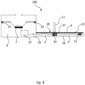
- Fig. 4 schematically illustrates a second embodiment of a hearing device 200.
- the hearing device 200 further comprises a microphone 14 which is configured to convert sound signal into an electrical signal.
- the microphone 14 is arranged in a second chamber 8 while the speaker 2 is arranged in the first chamber 4.
- the microphone 14 and the speaker 2 are interconnected by a wire 26.
- the wire 26 may comprise of multiple wires.
- the wire 26 may be connected to various electronics 27 and/or a battery arranged between the speaker 2 and the microphone 14.
- the hearing device 200 comprises both the microphone 14 and the speaker 2, the sound channel 6 is arranged between these two.
- the sound channel 6 allows any sound signal to travel there through. However, this may not be desirable especially if the microphone 14 picks up a signal generated by the speaker 2 and amplifies it. This effect can cause oscillations and instability which lead to a howling sound produced by the hearing device.
- An acoustic feedback path formed between the microphone 14 and the speaker 2 may need to be closed in order to prevent undesired howling sound and various instabilities which may appear during operation of the hearing device 200.
- the acoustic path can be closed by sealing at least a part of the sound channel 6 and thereby preventing the signal from the speaker 2 to travel back to the microphone 14.
- an element 10 made of thermoplastic is arranged in the sound channel 6.
- the element 10 may be positioned anywhere in the sound channel 6, however in a preferred embodiment, the element 10 is positioned either close to the microphone 14 or closer to the speaker 2.
- the element 10 is arranged in a compartment 22 which may define a way of element reshaping once a laser light 12 is applied onto the element 10. Besides the compartment 22 defining how the element 10 will melt and/or mould, melting of the element is controlled by controlling the laser light 12, i.e. its wavelength, duration of the application, strength, power, etc.
- Figs. 5 (a-c) illustrate a detailed view, which may be an actual design of the hearing device 200 shown in Fig. 4 .
- the hearing device 200 shown in Fig. 5(a) may represent an actual device of a headset comprising the speaker 2 and microphone 14 interconnected with the boom arm 28.
- Fig. 5(b) illustrates a bottom portion of the boom arm 28 in which the microphone 14 is visible as well as the wire 26 interconnecting the microphone 14 and the speaker.
- the element, comprising two portions 10a and 10b, is arranged around the wire 26 in the compartment 22 defined by the protrusions 24.
- Fig. 5(c) illustrates the top part 20 and the bottom part 18 forming a housing for the microphone 14 and further forming the boom arm.
- the top and bottom part may be made of materials which are transparent to the laser light.
- the headset 200 Before the laser light is applied to the, e.g., top part, the headset 200 may be completely assembled and sealing of the sound channel may be the last step in manufacturing of the headset 200. Namely, the laser light may be applied to the top part which is transparent to the laser. It is beneficial to create the sealing in the sound channel after the headset 200 has been assembled as in that way it is ensured that the entire cross-section of the sound channel is sealed.
- Figs. 6 (a-d) schematically illustrate formation of a seal in a sound channel.
- Fig. 6(a) illustrates a top view of a portion of the boom arm 28 of the headset 200 shown in Fig. 5 and arrangement of the element, comprising two portions 10a and 10b arranged next to each other and around the wire 26 before the laser light 12 has been applied. It should be noted that two portions of the element, 10a and 10b may alternatively be arranged on top of each other having the wire 26 sandwiched there between.
- the protrusions 24 are formed in the bottom part 18 thereby forming the compartment in which the elements 10a and 10b are arranged.
- the top part (not shown) is arranged and then the laser light 12 is applied onto the element, through the top part.
- the laser light 12 can be applied through the bottom part 18 or through both the top part and the bottom part 18.
- the wire 26 may remain fixed around the center of seal formed from the element.
- the wire 26 remains unaffected by the laser light 12.
- the wire 26 may comprise an insulation material transparent to the laser light 12.
- the wire 26 typically has a plastic coating.
- the coating may be coloured in a number of different colours. The selected colour of the coating may depend on the wavelength of the laser light. For wavelengths typically used for laser welding suitable colours may be white for ground and red for phase. Use of other colours is also possible, such as use of yellow, blue, orange, green, and similar. Typically, if the coating is black it will interact with the laser light 12 and melt what is not desirable. Additionally, the wire 26 may be secured in a tube transparent to the laser light 12.
- Fig. 6(b) illustrates the seal 30 formed after application of the laser light. It can be seen that the element is melted in such a way that it flows into space defined by the protrusions 24 and over the wire filling out the cross-section of the sound channel 6.
- Fig. 6(c) illustrates a side view of a portion of the boom arm 28 of the headset 200 shown in Fig. 5 and arrangement of the element 10 before the laser light has been applied. It can be noticed that the size of the compartment is slightly smaller than the size of the element. Larger size of the element 10 compared to the compartment provides for excess amount of the element to leak out of the compartment thereby providing a tight seal without any air gaps.
- Fig. 6(d) illustrates a side view of the seal 30 formed after application of the laser light 12.
Description
- The present disclosure relates to a method for manufacturing a hearing device by use of a laser light.
- Hearing devices are used in a wide variety of everyday life activities. The hearing devices include one or more speakers enclosed in speaker chambers. Sound channels are typically arranged between, e.g., surroundings and the speaker chamber. These sound channels may provide an acoustic path which is undesired and in order to provide the hearing device with the best properties, the undesired sound path needs to be acoustically sealed or blocked. Further, in hearing devices comprising a microphone and the speaker, there is a requirement to block the acoustic path between the microphone and the speaker as sound from the speaker may get amplified by the microphone which creates howling in the hearing device. Blocking unwanted sound channels in the hearing devices is a requirement in many hearing device designs.
- Expanding closed-cell-foams have been previously used to block a sound path in hearing devices. Foam is difficult to control and thereby not convenient for use in the manufacturing process. Silicone glue is also used in many products existing on the market. However, glue is difficult to handle especially because of the texture of glue, such as the viscosity of glue changing rapidly if glue is stationary during the sealing of the sound channel what may cause excessive amounts of wasted glue during device manufacturing. Glue is sensitive to changes in temperature and humidity and therefore may create additional storage requirements of the hearing devices in order to let the glue cure and/or remain in a certain condition. Furthermore, glue is expensive. Further, double adhesive tapes may be used to block sound path, however only for small gaps openings.
-
US 8,311,255 B2 discloses a method for manufacturing a headset in which, in order to prevent sound from receiver to leak into the headset's primary housing, a silicon glue is used. - "Controlling Heat Curing Adhesive Processes Using Infrared Spot Curing", Medical Design Briefs, 1 January 2012 relate to infrared fibres that provide precision heating and curing of glues in medical device assemblies.
-
US 2016/0165335 A1 discloses a manufacture process of a loudspeaker by using adhesive put around an edge of a dome diaphragm and a resilient member. - Therefore, there is a need to for an improved method to solve problems of the prior art.
- It is an object of embodiments of the present invention to provide a method for manufacturing a hearing device in which an unwanted sound channel is sealed in a controlled manner.
- It is a further object of the embodiments of the present invention to provide a simple and inexpensive method for manufacturing a hearing device.
- It is a yet further object of embodiments of the present invention to provide a method for manufacturing a hearing device in which an unwanted sound channel is sealed from outside of the device having the hearing device already assembled.
- It is a yet further object of embodiments of the present invention to provide a method for sealing a sound channel of a hearing device of any size.
- The invention is defined by independent claims 1 and 17.
- Thus, the invention provides a method for manufacturing a hearing device comprising a sound channel and wherein the sound channel is sealed by a thermoplastic element being in a solid state. The element is heated by a laser light and thereby transformed into a liquid state in a controlled manner.
- The hearing device may be a cabinet speaker or any other type of loudspeaker, receiver or speaker, a headset, a hearing aid, or the like.
- The hearing device comprises a speaker which is configured for converting an electrical audio signal into a corresponding sound. The hearing device may comprise more than one speaker. The speakers may be placed in different separate compartments inside the hearing device. The speaker(s) of the hearing device may comprise a membrane which vibrates during sound generation. Due to membrane vibrations there is a pressure difference between a front and rear side of the membrane. This pressure difference and the membrane causes sound generation.
- A first chamber is to be understood as a space which allows for sound generation. It may be a space in front of the speaker or it may be a space behind the speaker. Alternatively, it may be a space above the speaker or it may be a space below the speaker. The first chamber may be a space where the speaker is secured, attached or fixed.
- A sound channel is arranged between the first chamber and the surroundings of the hearing device or between the first chamber and a second chamber. In most of designs of the hearing devices, an acoustic path in the sound channel is undesired. There is a requirement in many hearing devices designs to acoustically seal the sound channel and prevent instabilities and undesired sound oscillations due to acoustic feedback in the hearing devices. The second chamber may be a space in front of the speaker or it may be a space behind the speaker. Alternatively, it may be a space above the speaker or it may be a space below the speaker. The second chamber defines a space different from the first chamber.
- According to the invention, an element of a thermoplastic material is arranged in the sound channel. The element is in a solid state and may be in a form of a rectangular block, a sphere, a circular or oval ring, or similar. The shape of the element may be determined by the cross-section of the sound channel. The element in the solid state is to be activated/melted by heat to thereby seal the sound channel.
- A laser light is applied to the element to thereby activate the element to change from the solid state to a liquid state. The laser light may be characterized by its wavelength, power, energy, intensity, and similar. The wavelength of the laser light may be chosen such that it provides interaction with the thermoplastic material of the element and thereby activation of the element and transformation of its state from solid to liquid. The laser light may be applied to the element for a very short time, such as for 1 second or shorter. The duration of the laser light application may depend on the size of the element, the volume of the sound channel and/or its cross-section, and/or it may depend on various properties of the thermoplastic material. When the laser light is applied to the element it provides energy to the element and thereby heat. The thermoplastic material typically softens when heated and hardens when cooled. Therefore, by applying the laser light having a suitable wavelength to the element, the element softens taking an intermediate state between solid and liquid, and then transforms into liquid which seals the sound channel. The thermoplastic material can be heated and cooled several times without any change in its chemical or mechanical properties. It means that the laser light can be applied to the element several times until a required sealing is achieved. Namely, the step of applying the laser light to the element may be started and restarted many times without any risk of wasting the material, or a need to replace the element after a restart of the laser application. This reduces overall cost of the manufacturing process.
- The sound channel is sealed as the element changes its state from the solid state to the liquid state. During this change in the state, the element fills out a cross-section of the sound channel. When the cross-section of the sound channel is filled with the element there may not be any air flow between the first chamber and the surroundings or between the first chamber and the second chamber. The element may fill out only a part of the entire volume of the sound channel, such as 10% of the volume or less.
- In the last step of the method, the element cools and thereby changes its state from the liquid state back to the solid state while filling out the cross-section of the sound channel. Cooling of the element may start as soon as the laser light is no longer applied to the element. Depending on the properties of the thermoplastic material used for the element, the cooling step may be as rapid as the step of heating, i.e. duration of the laser light application.
- Sealing of the sound channel performed by the laser light interacting with the thermoplastic material is a controlled process in which by controlling the laser light properties, such as intensity, wavelength, energy, duration of application, etc., the thermoplastic element is precisely moulded. Additionally, initial amount of the thermoplastic material used can be accurately controlled as it is in the solid state before the laser light is applied. Therefore, an overflow of the thermoplastic material when it is transformed into the liquid state cannot occur as the amount of thermoplastic material is precisely determined prior to application of the laser light and its flow when in the liquid state can also be controlled by the laser light. The thermoplastic material can provide sealing of sound channels of any size, ranging from sound channels in large cabinet speakers to sound channels in hearing aids. Even if the thermoplastic material forms a seal which is not in line with a targeted shape, the process can be repeated until a desired seal is achieved. Furthermore, by controlling the laser light, state change is accurately controlled and handling of liquid is improved to a great extent.
- The hearing device may further comprise a microphone, wherein the speaker may be arranged in the first chamber and the microphone may be arranged in the second chamber. The microphone converts sound into an electrical signal. When the hearing device comprises both the microphone and the speaker, the sound channel is typically provided between these two and in particular due to wiring. In such scenario, an acoustic feedback path is created in the sound channel. Namely, a portion of the sound coming from the speaker may travel through the sound channel, be picked up by the microphone, then amplified by the speaker, and radiated back into the surroundings of the hearing device. Furthermore, the amplified portion of the sound may be radiated back into the microphone, and so forth. This repeating cycle of sound amplification is undesired as it can create instability in the hearing device functioning, generate buzzing and howling. In order to prevent these undesired effects, the sound path between the speaker and the microphone may need to be closed.
- The hearing device may further comprise a speaker housing, the first chamber and the second chamber being arranged in the speaker housing. In this embodiment, the speaker may be a separation between the first and second chamber and the speaker housing may represent an enclosure of the hearing device. The speaker may be arranged on a printed circuit board carrying various electronics comprised in the hearing device. The printed circuit board may then define a border between the first and second chamber. The sealing to be created between the first and the second channel may also serve as a sealing between the surroundings of the hearing device and the interior of the speaker housing.
- If the hearing device is a cabinet speaker, the speaker housing encloses together with the speaker the first chamber, typically called a rear chamber. If the hearing device is a closed headset/headphone, the speaker housing, the speaker, an ear cushion, and the user's head encloses the first, i.e. front, chamber and the second, i.e. rear, chamber. The front chamber is arranged between the front of the speaker and the user's ear. Thus, the speaker membrane acts as a dividing wall between the rear chamber and the front chamber. If the hearing device is an open headphone, there is no closed front chamber. In this embodiment, it is desired to prevent uncontrolled leakage between the rear chamber and the front chamber. Therefore, undesired sound paths occurring due to unavoidable part tolerances should be minimised.
- The hearing device may comprise a bottom part and a top part and the element may be provided in a compartment defined by at least a portion of the bottom part and by at least a portion of the top part, and wherein the compartment is further defined by at least one protrusion extending into the interior of the sound channel of hearing device. The top part and the bottom part may be made of any material. They may be made of a plastic material. The plastic material which may be used for the top and bottom part of the hearing device may have properties which significantly differ from the properties of the thermoplastic material used for the element, especially in properties related to a melting temperature as at least a portion of the top and/or bottom part may be exposed to the laser light during hearing aid manufacturing. The manufacturing method may further comprise steps of:
- providing the bottom part and the top part prior to the step of arranging the element; and
- assembling the hearing device by connecting the bottom part and the top part after the step of arranging the element.
- In this way, the method provides a hearing device in which the sound channel is sealed from outside of the device having the hearing device already assembled.
- The compartment in which the element may be provided may be defined by protrusions extending towards the sound channel and being formed in the bottom and/or the top part of the hearing device. Preferably, there are four protrusions arranged such that they form a space in the canal of the bottom part of the hearing device. The formed space may have spherical shape, rectangular shape, etc., depending on the shape of the top and bottom part of the hearing device. The compartment can be understood as structural borders created to control reshaping and flow of the element when the element is in the liquid state. The size/volume of the compartment may be slightly smaller than the size/volume of the element, such as less than 10% smaller. Larger size/volume of the element compared to the compartment may be needed as excess amount of the element may leak out of the compartment thereby providing a tight seal without any air gaps.
- The top part may be made of a material transparent to the laser light and wherein the bottom part may be made of a material non-transparent to the laser light. In this embodiment, the laser light may be directed at the top part. Alternatively, the top part may be made of a material non-transparent to the laser light and the bottom part may be made of a material transparent to the laser light. In this embodiment, the laser light may be directed to the transparent bottom part. The material transparent to the laser light may not interact with the laser light and may not be influenced by the laser light. Namely, the material transparent to the laser light allows the transport of light without or with a minor light-matter interaction. The material which is non-transparent to the laser light is to be understood as a material which can absorb majority of the laser light applied to it. Transparency and non-transparency of the material depend on a laser wavelength. Therefore, the wavelength of the laser light to be used may depend on the materials used for the hearing device, and in particular the material of the element. By choosing the top and/or bottom part to be made of a material transparent to the laser light it is possible to direct the laser light towards the top and/or bottom part and thereby perform sealing of the sound channel from the outside the hearing device and having the hearing device already assembled.
- In an alternative embodiment, both the top part and the bottom part may be made of a material transparent to the laser light. By having both the top and bottom part of the hearing device made of the material transparent to the laser light, sealing can be performed by applying the laser light from any direction, i.e. both from the top and/or bottom part of the hearing device thereby providing for a flexible arrangement of the laser with respect to the hearing device. Furthermore, if the laser light is applied to only, e.g., top part, the light will interact only with the element as the bottom part is transparent to the laser light.
- In one embodiment, the element may be provided closer to the second chamber than to the first chamber. When providing the element closer to the second chamber, i.e. closer to one of the ends of the hearing device mechanical properties of the hearing device are improved. Namely, a boom arm may be provided between the first chamber and the second chamber, i.e. connecting the first and second chamber. When the element is provided at one end of the boom arm, flexibility of the boom arm is also improved. Flexibility of the hearing device is important as the hearing device may be exposed to various forces which may cause breaking of the device.
- In an alternative embodiment, the element may be provided closer to the first chamber than to the second chamber. As in the previously described embodiment, mechanical properties, and especially flexibility of the hearing device is improved. In contrast, if the element is arranged around the center of the boom arm, i.e. at around the same distance from both the first and second chamber, the boom arm may be less flexible and therefore more prone to breaking.
- In principle, the element may be provided anywhere in the sound channel, and may be of any size. If the hearing device comprises the boom arm, it is preferred that only a small portion of the boom arm is blocked by the element, and not the entire boom arm. If the entire boom arm is filled by the element, the arm may, due to larger stiffness, be more prone to breaking. Positioning of the element and choosing its size may be determined with respect to mechanical requirements, especially shock pressure allowed for the hearing device.
- The hearing device may comprise one or more wires interconnecting the speaker and the microphone, and the one or more wires may be arranged in the sound channel and through the element. The one or more wires may be arranged in the boom arm that may need to be sealed. The wires typically interconnect the microphone, i.e. a tip of the microphone, with electronics arranged in the hearing device. The electronics is further interconnected with a battery and other electronics arranged in the housing of the hearing device which are then further interconnected with the speaker. Having the wires arranged in the sound channel and through the element improves sound generated by the hearing device.
- In one embodiment, the element may comprise two portions and the one or more wires may be arranged between the two portions. The two portions of the element may be made from the same thermoplastic material or they may be made from two different ones. In this embodiment, the method for manufacturing the hearing device may further comprise:
- arranging a first portion of the element in the sound channel, the first portion of the element being in a solid state;
- arranging the one or more wires interconnecting the speaker and the microphone, the one or more wires being arranged on top of the first portion of the element;
- arranging a second portion of the element in the sound channel and besides or on top of the first element and the one or more wires;
- applying the laser light to the element thereby causing a change in state of the element;
- sealing the sound channel as the first portion and the second portion of the element transform into the liquid state thereby filling out the cross-section of the sound channel;
- allowing cooling of the first portion and the second portion of the element thereby causing a change in state of the element from the liquid state back to the solid state.
- When the element changes its state upon the laser light application, the one or more wires may remain fixed around the center of the element while being unaffected by the laser light. By having the element comprising the two portions a more reliable sealing around the wire may be obtained. Regardless of the element comprising two or more portions, only one step of laser application may be required. When the element is melted, it may flow around the wire closing even the smallest air gaps existing in the vicinity of the wire.
- In order to avoid interaction between the laser light and the wire, the wire may comprise an insulation material transparent to the laser light. The wire typically has a plastic insulation. When the insulation is transparent to the laser light it would not melt when the laser light is applied to the element. The insulation may be coloured in a number of different colours. The selected colour of the insulation may depend on the wavelength of the laser light. For wavelengths typically used for laser welding suitable colours may be white for ground and red for phase. Use of other colours is also possible, such as use of yellow, blue, orange, green, and similar. Typically, if the insulation is dark it will interact with the laser light and melt what is not desirable. Additionally, the wire may be secured against electrostatic discharge in a tube transparent to the laser light.
- The thermoplastic material may be a thermoplastic adhesive. The thermoplastic adhesive is a heat-activated adhesive which may generate joint strength almost instantly after cooling. The thermoplastic adhesive is composed such that it melts at a lower temperature that the melt temperature of the material forming the sound channel, e.g. the top and bottom part of the hearing device. When using the thermoplastic adhesive, the sealing process is fast and liquid waste is reduced to minimum.
- The thermoplastic adhesive may be a hot melt adhesive, such as a hot melt glue. The hot melt glue is activated by heat generated by the laser light and provides a desired seal of the sound channel which is easy to disassemble and repair if needed. Further, storage requirements of the hearing device is simpler compared to seals formed by, e.g., expanding foams, silicone glue, standard glue, or double adhesive tapes. Furthermore, the hot melt glue are not limited to sealing only small size sound channels but may seal sound channels of any size, i.e., in hearing devices of any size ranging from cabinet speakers to miniature hearing aids.
- The thermoplastic material may have a melting point which is lower than a melting point of the top part and a melting point of the bottom part, the melting point of the thermoplastic material may be in the range between 85°C and 100°C. Melting points of the top part and the bottom part may be in the range between 230°C and 290°C. A relatively low melting temperature of the element allows for softening and melting of the element while other parts which are also exposed to the laser light are not influenced by heat produced by the laser.
- The laser light may be a continuous wave laser light, and the wavelength of the laser light may be about 985 nm. The wavelength of the laser may be tuned in a range from 950 nm up to 1050 nm depending on the exact chemical properties of the element used in the hearing device. As mentioned above, the laser light is chosen to fit the thermoplastic material of the element, as well as the material used for other parts of the hearing device which may be exposed to the laser light during the sealing process. The continuous wave laser light provides a concentrated heat source, allowing for narrow and precise welds which are desired in a hearing device industry, especially in hearing aids which are becoming smaller and smaller every year. Further, the laser light may have high power density resulting in small heat-affected zones and high heating rates. When using the laser with high power density, the sealing of the sound channel can be achieved in several seconds including both application of the laser light melting the element and cooling of the element when the element is transformed back into the solid state. Power density of the laser may be in the order of 0,1 MW/cm2 up to 2 MW/cm2. It can be varied/controlled depending on the size of the sound channel and various properties of the element.
- The laser light may be applied by guiding the light towards the element by means of at least one mirror arranged on a fixture, the mirror reflecting the laser light. The laser light/mirror(s) can be moved relative to the hearing device, and/or the hearing device to be manufactured can be moved relative the laser light/mirrors. Preferably, two mirrors are used and the laser and the hearing device are steady while the mirrors or the fixture are moving in order to direct the laser beam onto the entire surface of the element. The mirrors may also be arranged such that the laser light falls onto the element. In one arrangement, the laser may be moving while the mirror(s) and the hearing device are steady. Having the mirrors arranged on the fixture allows for a large flexibility of the manufacturing process. Alternatively, the laser itself may comprise additional movable mirrors in its galvo-head which may then direct the laser light towards the element.
- In the second aspect, the invention provides a hearing device being manufactured by a method according to the first aspect presented above.
- In the third aspect, the invention provides a hearing device comprising:
- a first chamber;
- a second chamber;
- a speaker;
- a sound channel arranged between the first chamber and the surroundings of the hearing device or the second chamber;
- an element of a thermoplastic material, the element configured to be activated by a laser light and to change from a solid state to a liquid state during manufacturing, the element being configured to seal the sound channel by means of the element changing from the solid state to the liquid state.
- A skilled person would readily understand that any feature described in combination with the first aspect of the invention could also be combined with the second and third aspects of the invention, and vice versa. Accordingly, the remarks set forth above with reference to the first aspect of the invention are equally applicable to the second and third aspect.
- The present invention relates to different aspects including the method described above and in the following, and corresponding hearing devices, methods, devices, systems, networks, kits, uses, processes, products-by-process, and/or product means, each yielding one or more of the benefits and advantages described in connection with the first mentioned aspect, and each having one or more embodiments corresponding to the embodiments described in connection with the first mentioned aspect and/or disclosed in the appended claims.
- The above and other features and advantages will become readily apparent to those skilled in the art by the following detailed description of exemplary embodiments thereof with reference to the attached drawings, in which:
-
Fig. 1 schematically illustrates a first embodiment of a hearing device; -
Figs. 2 (a-c) illustrate a detailed view of the embodiment of the hearing device shown inFig. 1 ; -
Figs. 3 (a) and (b) illustrate a perspective view of the hearing device shown inFig. 2 ; -
Fig. 4 schematically illustrates a second embodiment of a hearing device; -
Figs. 5 (a-c) illustrate a detailed view of the hearing device shown inFig. 4 ; and -
Figs. 6 (a-d) schematically illustrate formation of a seal in a sound channel. - Various embodiments are described hereinafter with reference to the figures. Like reference numerals refer to like elements throughout. Like elements will, thus, not be described in detail with respect to the description of each figure. It should also be noted that the figures are only intended to facilitate the description of the embodiments. They are not intended as an exhaustive description of the claimed invention or as a limitation on the scope of the claimed invention. In addition, an illustrated embodiment needs not have all the aspects or advantages shown. An aspect or an advantage described in conjunction with a particular embodiment is not necessarily limited to that embodiment and can be practiced in any other embodiments even if not so illustrated, or if not so explicitly described.
- Throughout, the same reference numerals are used for identical or corresponding parts.
-
Fig. 1 schematically illustrates a first embodiment of ahearing device 100. A cross-section of thehearing device 100 is illustrated. Thehearing device 100 comprises aspeaker 2, afirst chamber 4, and asound channel 6 arranged between thefirst chamber 4 and thesecond chamber 8. Thesound channel 6 is also arranged between thefirst chamber 4 and asecond chamber 8 and the surroundings of thehearing device 100 or thesecond chamber 8. Thehearing device 100 comprises aspeaker housing 16 enclosing thespeaker 2 and other parts of thehearing device 100. Anelement 10 of a thermoplastic material and being in a solid state is arranged in thesound channel 6. Alaser light 12 is applied to theelement 10 to thereby activate theelement 10 to change from the solid state to a liquid state. Thesound channel 6 is sealed by means of theelement 10 changing from the solid state to the liquid state thereby filling out a cross-section of thesound channel 6. Once thelaser light 12 is switched off, theelement 10 cools and thereby change from the liquid state to solid state while filling out the cross-section of thesound channel 6. - In
Fig. 1 , twolaser beams 12 are arranged to activate the element and thereby seal thesound channel 6. Alternatively, only onelaser beam 12 may be applied and then moved along theelement 10. Alternatively, mirrors can be used to direct thelaser light 12 onto theelement 10. Further, thelaser light 12 is applied through atop part 20 of thehearing device 100. In this scenario, thetop part 20 is made of a material which is transparent to thelaser light 12. - Alternatively, the
laser light 12 may be applied through abottom part 18 which is then made of a material transparent to thelaser light 12.Protrusions 24 are arranged in thesound channel 6 to define how theelement 10 will melt under thelaser light 12 and thereby seal thesound channel 6. -
Figs. 2 (a-c) illustrate a detailed view of the embodiment of thehearing device 200 shown inFig. 1 .Fig. 2(a) shows a top view of thetop part 20 defining the first (speaker)chamber 4 and the second (microphone)chamber 8 and theelement 10 arranged in such a manner to provide the sealing between themicrophone chamber 8 and thespeaker chamber 4. Theelement 10 may have a width of 0.8 mm. Awelding area 11 for ensuring a mechanical bond between thetop part 20 and the bottom part is also arranged in thetop part 20.Fig. 2(b) illustrates the assembledhearing device 100 assembled by connecting thetop part 20 and thebottom part 18.Fig. 2(c) illustrates the assembleddevice 100 onto which thelaser light 12 is applied onto the element in order to seal the microphone chamber from the speaker chamber. In this embodiment, thelaser light 12 is applied at two different places targeting the element at two different positions.More laser beams 12 may also be applied. Thelaser light 12 and the welding beams 13 are applied through thebottom part 18. Welding beams 13 are applied onto the welding area in order to ensure mechanical bonding between thebottom part 18 and thetop part 20. Thewelding area 11 may be non-transparent to thewelding beam 13. Thenon-transparent welding area 11 will then be heated and melted by thelaser welding beam 13. Also, a corresponding area of thebottom part 18 may be non-transparent to thewelding beam 13 and will therefore melt under the welding beam. The twoparts bottom pat 18 and thetop part 20 are transparent to thewelding beam 13, one of the surfaces may be painted dark, whereby heat will build up and melt the two surfaces together. -
Figs. 3 (a) and (b) illustrate a perspective view of the hearing device shown inFig. 2 .Fig. 3(a) shows thebottom part 18 and thetop part 20 before the laser light has been applied. Theelement 10 is arranged in thetop part 20 to seal the sound channel arranged between thefirst chamber 4 and thesecond chamber 8. In this embodiment, theelement 10 is arranged on the top of a relatively long curved rib in order to seal the sound path which occurs between themicrophone chamber 8 and thespeaker chamber 4. Thewelding area 11 is also arranged in thetop part 20. Once the laser light is applied theelement 10 is melted and the seal between thebottom part 18 and thetop part 20 is formed. This is shown inFig. 3(b) . Thefirst chamber 4 and thesecond chamber 8 may be separated by a printed circuit board (not shown). Thetop part 20 and thebottom part 18 together form part of the speaker housing. The embodiment shown inFig. 3(b) may represent an actual design of thehearing device 100. It can be seen that the element10 can be precisely applied/defined as it is in the solid state. It is beneficial as an overflow of the thermoplastic material when it is transformed into liquid cannot occur as the amount of the thermoplastic material is precisely determined prior to application of the laser light. Furthermore, a shape of the element10 can be defined based on an area to be sealed and shaping can be performed anywhere and not while the thermoplastic material is in contact with thetop part 20. -
Fig. 4 schematically illustrates a second embodiment of ahearing device 200. A number of features explained in relation toFig. 1 are equally applicable to this embodiment and therefore will not be described in details, we hereby refertoFig. 1 . In this embodiment, thehearing device 200 further comprises amicrophone 14 which is configured to convert sound signal into an electrical signal. Themicrophone 14 is arranged in asecond chamber 8 while thespeaker 2 is arranged in thefirst chamber 4. Themicrophone 14 and thespeaker 2 are interconnected by awire 26. Thewire 26 may comprise of multiple wires. Thewire 26 may be connected tovarious electronics 27 and/or a battery arranged between thespeaker 2 and themicrophone 14. When thehearing device 200 comprises both themicrophone 14 and thespeaker 2, thesound channel 6 is arranged between these two. Thesound channel 6 allows any sound signal to travel there through. However, this may not be desirable especially if themicrophone 14 picks up a signal generated by thespeaker 2 and amplifies it. This effect can cause oscillations and instability which lead to a howling sound produced by the hearing device. An acoustic feedback path formed between themicrophone 14 and thespeaker 2 may need to be closed in order to prevent undesired howling sound and various instabilities which may appear during operation of thehearing device 200. The acoustic path can be closed by sealing at least a part of thesound channel 6 and thereby preventing the signal from thespeaker 2 to travel back to themicrophone 14. In order to seal thesound channel 6, anelement 10 made of thermoplastic is arranged in thesound channel 6. In principle, theelement 10 may be positioned anywhere in thesound channel 6, however in a preferred embodiment, theelement 10 is positioned either close to themicrophone 14 or closer to thespeaker 2. By placing theelement 10 at one end of aboom arm 28 mechanical properties of thehearing device 200 are improved. Theelement 10 is arranged in acompartment 22 which may define a way of element reshaping once alaser light 12 is applied onto theelement 10. Besides thecompartment 22 defining how theelement 10 will melt and/or mould, melting of the element is controlled by controlling thelaser light 12, i.e. its wavelength, duration of the application, strength, power, etc. -
Figs. 5 (a-c) illustrate a detailed view, which may be an actual design of thehearing device 200 shown inFig. 4 . Thehearing device 200 shown inFig. 5(a) may represent an actual device of a headset comprising thespeaker 2 andmicrophone 14 interconnected with theboom arm 28.Fig. 5(b) illustrates a bottom portion of theboom arm 28 in which themicrophone 14 is visible as well as thewire 26 interconnecting themicrophone 14 and the speaker. The element, comprising twoportions wire 26 in thecompartment 22 defined by theprotrusions 24. When thelaser light 12 is applied to theelements wire 26 thereby sealing the cross-section of the sound channel arranged between themicrophone 14 and the speaker. Fig. 5(c) illustrates thetop part 20 and thebottom part 18 forming a housing for themicrophone 14 and further forming the boom arm. Depending on where the laser light is to be applied, the top and bottom part may be made of materials which are transparent to the laser light. Before the laser light is applied to the, e.g., top part, theheadset 200 may be completely assembled and sealing of the sound channel may be the last step in manufacturing of theheadset 200. Namely, the laser light may be applied to the top part which is transparent to the laser. It is beneficial to create the sealing in the sound channel after theheadset 200 has been assembled as in that way it is ensured that the entire cross-section of the sound channel is sealed. -
Figs. 6 (a-d) schematically illustrate formation of a seal in a sound channel.Fig. 6(a) illustrates a top view of a portion of theboom arm 28 of theheadset 200 shown inFig. 5 and arrangement of the element, comprising twoportions wire 26 before thelaser light 12 has been applied. It should be noted that two portions of the element, 10a and 10b may alternatively be arranged on top of each other having thewire 26 sandwiched there between. Theprotrusions 24 are formed in thebottom part 18 thereby forming the compartment in which theelements element portions wire 26, the top part (not shown) is arranged and then thelaser light 12 is applied onto the element, through the top part. Alternatively, thelaser light 12 can be applied through thebottom part 18 or through both the top part and thebottom part 18. When theelements wire 26 may remain fixed around the center of seal formed from the element. Thewire 26 remains unaffected by thelaser light 12. By having the element comprising the two or more portions a more reliable sealing is obtained as a better flow of the meltedelement 10 around thewire 26 is provided. Regardless of the element comprising two or more portions, only one step of laser application may be required. When the element is melted, it may flow around thewire 26 closing even the smallest air gaps existing in the vicinity of thewire 26. - In order to avoid interaction between the
laser light 12 and thewire 26, thewire 26 may comprise an insulation material transparent to thelaser light 12. Thewire 26 typically has a plastic coating. When the coating is transparent to thelaser light 12 it would not melt when thelaser light 12 is applied to theelements laser light 12 and melt what is not desirable. Additionally, thewire 26 may be secured in a tube transparent to thelaser light 12. -
Fig. 6(b) illustrates theseal 30 formed after application of the laser light. It can be seen that the element is melted in such a way that it flows into space defined by theprotrusions 24 and over the wire filling out the cross-section of thesound channel 6. -
Fig. 6(c) illustrates a side view of a portion of theboom arm 28 of theheadset 200 shown inFig. 5 and arrangement of theelement 10 before the laser light has been applied. It can be noticed that the size of the compartment is slightly smaller than the size of the element. Larger size of theelement 10 compared to the compartment provides for excess amount of the element to leak out of the compartment thereby providing a tight seal without any air gaps. -
Fig. 6(d) illustrates a side view of theseal 30 formed after application of thelaser light 12. - Although particular features have been shown and described, it will be understood that they are not intended to limit the claimed invention, and it will be made obvious to those skilled in the art that various changes and modifications which fall under the scope of the appended claims may be made. The specification and drawings are, accordingly to be regarded in an illustrative rather than restrictive sense.
-
- 2
- speaker
- 4
- first chamber
- 6
- sound channel
- 8
- second chamber
- 10
- element
- 11
- welding area
- 12
- laser light
- 13
- welding laser beam
- 14
- microphone
- 16
- speaker housing
- 18
- bottom part
- 20
- top part
- 22
- compartment
- 24
- protrusion
- 26
- wire
- 27
- electronics
- 28
- boom arm
- 30
- seal
Claims (17)
- A method for manufacturing a hearing device (100, 200), the hearing device (100, 200) comprising a speaker (2), a first chamber (4), and a sound channel (6) arranged between the first chamber (4) and the surroundings of the hearing device (100, 200) or a second chamber (8), the method comprising:- arranging an element (10) of a thermoplastic material in the sound channel (6), the element (10) being in a solid state;- applying a laser light (12) to the element (10) to thereby activate the element (10) to change from the solid state to a liquid state;- sealing the sound channel (6) by means of the element (10) changing from the solid state to the liquid state thereby filling out a cross-section of the sound channel (6);- allowing cooling of the element (10) thereby a change of the element (10) from the liquid state to solid state while filling out the cross-section of the sound channel (6).
- A method according to claim 1, wherein the hearing device (100, 200) further comprises a microphone (14), and wherein the speaker (2) is arranged in the first chamber (4) and the microphone (14) is arranged in the second chamber (8).
- A method according to claim 1 or 2, wherein the hearing device (100, 200) further comprises a speaker housing (16), the first chamber (4) and the second chamber (8) being arranged in the speaker housing (16).
- A method according to any of the preceding claims, wherein the hearing device (100, 200) comprises a bottom part (18) and a top part (20) and wherein the element (10) is provided in a compartment (22) defined by at least a portion of the bottom part (18) and by at least a portion of the top part (20), and wherein the compartment (22) is further defined by at least one protrusion (24) extending into the interior of the sound channel (6) of hearing device (100, 200).
- A method according to claim 4, wherein the top part (20) is made of a material transparent to the laser light (12) and wherein the bottom part (18) is made of a material non-transparent to the laser light (12).
- A method according claim 4, wherein the top part (20) and the bottom part (18) are made of a material transparent to the laser light (12).
- A method according to any of the preceding claims, wherein the element (10) is provided closer to the second chamber (8) than to the first chamber (4).
- A method according to claims 1-6, wherein the element (10) is provided closer to the first chamber (4) than to the second chamber (8).
- A method according to claims 2-8, wherein the hearing device (100, 200) comprises one or more wires (26) interconnecting the speaker (2) and the microphone (14), and wherein the one or more wires (26) are arranged in the sound channel (6) and through the element (10).
- A method according to claim 9, wherein the element (10) comprises two portions (10a, 10b) and wherein the one or more wires (26) are arranged between the two portions (10a, 10b).
- A method according to claim 9 or 10, wherein the one or more wires (26) comprise an insulation material transparent to the laser light (12).
- A method according to any of the preceding claims, wherein the thermoplastic material is a thermoplastic adhesive.
- A method according to claim 12, wherein the thermoplastic adhesive is a hot melt adhesive, such as a hot melt glue.
- A method according to claims 4-13, wherein the thermoplastic material has a melting point which is lower than a melting point of the top part (20) and a melting point of the bottom part (18), the melting point of the thermoplastic material being in the range between 85°C and 100°C.
- A method according to any of the preceding claims, wherein the laser light (12) is a continuous wave laser light, and wherein the wavelength of the laser light (12) is about 985 nm.
- A method according to any of the preceding claims, wherein the laser light (12) is applied by guiding the light towards the element (10) by means of at least one mirror arranged on a fixture, the mirror reflecting the laser light (12).
- A hearing device (100, 200) comprising:- a first chamber (4);- a second chamber (8);- a speaker (2);- a sound channel (6) arranged between the first chamber (4) and the surroundings of the hearing device (100, 200) or the second chamber (8);- an element (10) of a thermoplastic material, arranged in the sound channel, the element (10) configured to be activated by a laser light (12) and to change from a solid state to a liquid state during manufacturing, the element (10) being configured to seal the sound channel (6) by means of the element (10) changing from the solid state to the liquid state.
Priority Applications (3)
| Application Number | Priority Date | Filing Date | Title |
|---|---|---|---|
| EP19185230.0A EP3764665B1 (en) | 2019-07-09 | 2019-07-09 | A method for manufacturing a hearing device |
| US16/913,552 US11691348B2 (en) | 2019-07-09 | 2020-06-26 | Method for manufacturing a hearing device |
| CN202010652329.1A CN112218226A (en) | 2019-07-09 | 2020-07-08 | Method for manufacturing hearing device and hearing device |
Applications Claiming Priority (1)
| Application Number | Priority Date | Filing Date | Title |
|---|---|---|---|
| EP19185230.0A EP3764665B1 (en) | 2019-07-09 | 2019-07-09 | A method for manufacturing a hearing device |
Publications (3)
| Publication Number | Publication Date |
|---|---|
| EP3764665A1 EP3764665A1 (en) | 2021-01-13 |
| EP3764665B1 true EP3764665B1 (en) | 2023-06-07 |
| EP3764665C0 EP3764665C0 (en) | 2023-06-07 |
Family
ID=67226012
Family Applications (1)
| Application Number | Title | Priority Date | Filing Date |
|---|---|---|---|
| EP19185230.0A Active EP3764665B1 (en) | 2019-07-09 | 2019-07-09 | A method for manufacturing a hearing device |
Country Status (3)
| Country | Link |
|---|---|
| US (1) | US11691348B2 (en) |
| EP (1) | EP3764665B1 (en) |
| CN (1) | CN112218226A (en) |
Family Cites Families (30)
| Publication number | Priority date | Publication date | Assignee | Title |
|---|---|---|---|---|
| US7010137B1 (en) * | 1997-03-12 | 2006-03-07 | Sarnoff Corporation | Hearing aid |
| EP0821542A3 (en) * | 1996-07-24 | 2004-06-02 | Bernafon AG | Hearing aid which is to be worn completely in the ear canal and which is individualised by moulding a body |
| US6751327B1 (en) * | 2000-07-11 | 2004-06-15 | Insonus Medical, Inc. | Miniature plastic battery assembly for canal hearing devices |
| US6741718B1 (en) * | 2000-08-28 | 2004-05-25 | Gn Jabra Corporation | Near-field speaker/microphone acoustic/seismic dampening communication device |
| EP1270183A1 (en) * | 2001-06-29 | 2003-01-02 | Nokia Corporation | Housing construction |
| WO2004007180A1 (en) * | 2002-07-12 | 2004-01-22 | E. I. Du Pont De Nemours And Company | A process for laser welding together articles of polyester resin compositions and related products |
| US7570777B1 (en) * | 2004-01-13 | 2009-08-04 | Step Labs, Inc. | Earset assembly |
| FI20041682A0 (en) * | 2004-12-29 | 2004-12-29 | Filtronic Lk Oy | A method for assembling a speaker chamber in a reproducing apparatus and a speaker chamber |
| US20080205679A1 (en) * | 2005-07-18 | 2008-08-28 | Darbut Alexander L | In-Ear Auditory Device and Methods of Using Same |
| US20080123866A1 (en) * | 2006-11-29 | 2008-05-29 | Rule Elizabeth L | Hearing instrument with acoustic blocker, in-the-ear microphone and speaker |
| DK2276269T3 (en) * | 2006-12-04 | 2014-09-22 | Sennheiser Comm As | Headphone with swivel parts |
| US8180093B2 (en) * | 2007-01-05 | 2012-05-15 | Apple Inc. | Assembly for coupling the housings of an electronic device |
| US20080166006A1 (en) * | 2007-01-06 | 2008-07-10 | Apple Inc | Light diffuser |
| JP5139766B2 (en) * | 2007-10-15 | 2013-02-06 | 日本電波工業株式会社 | Piezoelectric device and method for manufacturing piezoelectric device |
| US8818000B2 (en) * | 2008-04-25 | 2014-08-26 | Andrea Electronics Corporation | System, device, and method utilizing an integrated stereo array microphone |
| DE102009009273B4 (en) * | 2009-02-17 | 2014-08-21 | Siemens Medical Instruments Pte. Ltd. | Method for producing a hearing aid with indirect laser irradiation |
| JP5397051B2 (en) * | 2009-07-03 | 2014-01-22 | パナソニック株式会社 | Ultrasonic transducer and ultrasonic flowmeter using the same |
| JP6046329B2 (en) * | 2010-01-08 | 2016-12-14 | 早川ゴム株式会社 | Joining method using laser light |
| DE102010006469A1 (en) * | 2010-02-01 | 2011-08-04 | Siemens Medical Instruments Pte. Ltd. | Guide device for a listening device |
| US8549733B2 (en) * | 2010-07-09 | 2013-10-08 | Shure Acquisition Holdings, Inc. | Method of forming a transducer assembly |
| US8908897B2 (en) * | 2011-07-28 | 2014-12-09 | Plantronics, Inc. | Dual acoustic waveguide |
| US9258663B2 (en) * | 2012-09-07 | 2016-02-09 | Apple Inc. | Systems and methods for assembling non-occluding earbuds |
| US9247335B2 (en) * | 2013-03-14 | 2016-01-26 | Bose Corporation | Sealing wiring holes in electronic devices |
| US9398365B2 (en) * | 2013-03-22 | 2016-07-19 | Otter Products, Llc | Earphone assembly |
| GB2516876A (en) * | 2013-08-02 | 2015-02-11 | Pss Belgium Nv | A loudspeaker with a helmholtz resonator |
| WO2016112000A1 (en) * | 2015-01-05 | 2016-07-14 | Gecawicz Raymond | Modular headset with pivotable boom and speaker module |
| EP3505001B1 (en) * | 2015-09-30 | 2020-11-18 | Apple Inc. | Wireless pairing of earbuds and case |
| DK3367703T3 (en) * | 2017-02-27 | 2020-07-06 | Oticon As | HEARING DEVICE WITH A MICROPHONE STRUCTURE |
| CN206728248U (en) * | 2017-04-21 | 2017-12-08 | 深圳市三德大康电子有限公司 | Sports earphones |
| CN109108462A (en) * | 2018-08-02 | 2019-01-01 | 瑞声光电科技(常州)有限公司 | Microphone device and its assembly method |
-
2019
- 2019-07-09 EP EP19185230.0A patent/EP3764665B1/en active Active
-
2020
- 2020-06-26 US US16/913,552 patent/US11691348B2/en active Active
- 2020-07-08 CN CN202010652329.1A patent/CN112218226A/en active Pending
Also Published As
| Publication number | Publication date |
|---|---|
| US11691348B2 (en) | 2023-07-04 |
| EP3764665A1 (en) | 2021-01-13 |
| EP3764665C0 (en) | 2023-06-07 |
| CN112218226A (en) | 2021-01-12 |
| US20210008810A1 (en) | 2021-01-14 |
Similar Documents
| Publication | Publication Date | Title |
|---|---|---|
| EP3028473B1 (en) | A loudspeaker with a helmholtz resonator | |
| JP6323013B2 (en) | Resin bonded body and resin member bonding method | |
| WO2015159515A1 (en) | Gas permeation member and production method therefor | |
| US10298729B2 (en) | Connector and method of manufacturing the same | |
| EP3764665B1 (en) | A method for manufacturing a hearing device | |
| KR100788476B1 (en) | Structure of high quality sound microspeaker | |
| JP2015064431A (en) | Portable terminal and manufacturing method of the same | |
| WO2019184477A1 (en) | Sound production apparatus and electronic device | |
| US20050175298A1 (en) | Optical module aligned after assembly | |
| CN107925809A (en) | The microphone of advance sound formula and the method for manufacture | |
| JP3246183B2 (en) | Vibration member for speaker and method of manufacturing the same | |
| JP2009111205A (en) | Hollow package, manufacturing method thereof, assembling method thereof, and photographing device | |
| JP2006294367A (en) | Thin battery | |
| KR101489797B1 (en) | Bonded by heat fusion type of speakers, and the adhesive tape method | |
| CN109348374A (en) | A kind of loudspeaker | |
| WO2019041506A1 (en) | Resonator device module | |
| WO2021098010A1 (en) | Sound generation device module and electronic product | |
| JP4691906B2 (en) | Battery pack | |
| KR101249487B1 (en) | Pin welding method when armature type unit and apparatus thereof | |
| CN206596219U (en) | Sound-producing device module | |
| CN110636396A (en) | Sound production device and electronic product | |
| CN108540894B (en) | Earphone waterproof construction and bone conduction earphone | |
| JP3064180U (en) | Heating resistance heating element | |
| JP2018207485A (en) | Vacuum dual structure and method of manufacturing the same, and headphone | |
| JP4436580B2 (en) | Speaker manufacturing method |
Legal Events
| Date | Code | Title | Description |
|---|---|---|---|
| PUAI | Public reference made under article 153(3) epc to a published international application that has entered the european phase |
Free format text: ORIGINAL CODE: 0009012 |
|
| STAA | Information on the status of an ep patent application or granted ep patent |
Free format text: STATUS: THE APPLICATION HAS BEEN PUBLISHED |
|
| AK | Designated contracting states |
Kind code of ref document: A1 Designated state(s): AL AT BE BG CH CY CZ DE DK EE ES FI FR GB GR HR HU IE IS IT LI LT LU LV MC MK MT NL NO PL PT RO RS SE SI SK SM TR |
|
| AX | Request for extension of the european patent |
Extension state: BA ME |
|
| STAA | Information on the status of an ep patent application or granted ep patent |
Free format text: STATUS: REQUEST FOR EXAMINATION WAS MADE |
|
| 17P | Request for examination filed |
Effective date: 20210622 |
|
| RBV | Designated contracting states (corrected) |
Designated state(s): AL AT BE BG CH CY CZ DE DK EE ES FI FR GB GR HR HU IE IS IT LI LT LU LV MC MK MT NL NO PL PT RO RS SE SI SK SM TR |
|
| GRAP | Despatch of communication of intention to grant a patent |
Free format text: ORIGINAL CODE: EPIDOSNIGR1 |
|
| STAA | Information on the status of an ep patent application or granted ep patent |
Free format text: STATUS: GRANT OF PATENT IS INTENDED |
|
| RIC1 | Information provided on ipc code assigned before grant |
Ipc: H04R 31/00 20060101AFI20220923BHEP |
|
| INTG | Intention to grant announced |
Effective date: 20221020 |
|
| GRAS | Grant fee paid |
Free format text: ORIGINAL CODE: EPIDOSNIGR3 |
|
| GRAA | (expected) grant |
Free format text: ORIGINAL CODE: 0009210 |
|
| STAA | Information on the status of an ep patent application or granted ep patent |
Free format text: STATUS: THE PATENT HAS BEEN GRANTED |
|
| AK | Designated contracting states |
Kind code of ref document: B1 Designated state(s): AL AT BE BG CH CY CZ DE DK EE ES FI FR GB GR HR HU IE IS IT LI LT LU LV MC MK MT NL NO PL PT RO RS SE SI SK SM TR |
|
| REG | Reference to a national code |
Ref country code: GB Ref legal event code: FG4D |
|
| REG | Reference to a national code |
Ref country code: CH Ref legal event code: EP Ref country code: AT Ref legal event code: REF Ref document number: 1578281 Country of ref document: AT Kind code of ref document: T Effective date: 20230615 |
|
| REG | Reference to a national code |
Ref country code: DE Ref legal event code: R096 Ref document number: 602019029808 Country of ref document: DE |
|
| U01 | Request for unitary effect filed |
Effective date: 20230704 |
|
| U07 | Unitary effect registered |
Designated state(s): AT BE BG DE DK EE FI FR IT LT LU LV MT NL PT SE SI Effective date: 20230712 |
|
| REG | Reference to a national code |
Ref country code: LT Ref legal event code: MG9D |
|
| U20 | Renewal fee paid [unitary effect] |
Year of fee payment: 5 Effective date: 20230915 |
|
| PG25 | Lapsed in a contracting state [announced via postgrant information from national office to epo] |
Ref country code: NO Free format text: LAPSE BECAUSE OF FAILURE TO SUBMIT A TRANSLATION OF THE DESCRIPTION OR TO PAY THE FEE WITHIN THE PRESCRIBED TIME-LIMIT Effective date: 20230907 Ref country code: ES Free format text: LAPSE BECAUSE OF FAILURE TO SUBMIT A TRANSLATION OF THE DESCRIPTION OR TO PAY THE FEE WITHIN THE PRESCRIBED TIME-LIMIT Effective date: 20230607 |
|
| PGFP | Annual fee paid to national office [announced via postgrant information from national office to epo] |
Ref country code: GB Payment date: 20230920 Year of fee payment: 5 |
|
| PG25 | Lapsed in a contracting state [announced via postgrant information from national office to epo] |
Ref country code: RS Free format text: LAPSE BECAUSE OF FAILURE TO SUBMIT A TRANSLATION OF THE DESCRIPTION OR TO PAY THE FEE WITHIN THE PRESCRIBED TIME-LIMIT Effective date: 20230607 Ref country code: HR Free format text: LAPSE BECAUSE OF FAILURE TO SUBMIT A TRANSLATION OF THE DESCRIPTION OR TO PAY THE FEE WITHIN THE PRESCRIBED TIME-LIMIT Effective date: 20230607 Ref country code: GR Free format text: LAPSE BECAUSE OF FAILURE TO SUBMIT A TRANSLATION OF THE DESCRIPTION OR TO PAY THE FEE WITHIN THE PRESCRIBED TIME-LIMIT Effective date: 20230908 |
|
| PG25 | Lapsed in a contracting state [announced via postgrant information from national office to epo] |
Ref country code: SK Free format text: LAPSE BECAUSE OF FAILURE TO SUBMIT A TRANSLATION OF THE DESCRIPTION OR TO PAY THE FEE WITHIN THE PRESCRIBED TIME-LIMIT Effective date: 20230607 |
|
| PG25 | Lapsed in a contracting state [announced via postgrant information from national office to epo] |
Ref country code: IS Free format text: LAPSE BECAUSE OF FAILURE TO SUBMIT A TRANSLATION OF THE DESCRIPTION OR TO PAY THE FEE WITHIN THE PRESCRIBED TIME-LIMIT Effective date: 20231007 |
|
| PG25 | Lapsed in a contracting state [announced via postgrant information from national office to epo] |
Ref country code: SM Free format text: LAPSE BECAUSE OF FAILURE TO SUBMIT A TRANSLATION OF THE DESCRIPTION OR TO PAY THE FEE WITHIN THE PRESCRIBED TIME-LIMIT Effective date: 20230607 Ref country code: SK Free format text: LAPSE BECAUSE OF FAILURE TO SUBMIT A TRANSLATION OF THE DESCRIPTION OR TO PAY THE FEE WITHIN THE PRESCRIBED TIME-LIMIT Effective date: 20230607 Ref country code: RO Free format text: LAPSE BECAUSE OF FAILURE TO SUBMIT A TRANSLATION OF THE DESCRIPTION OR TO PAY THE FEE WITHIN THE PRESCRIBED TIME-LIMIT Effective date: 20230607 Ref country code: IS Free format text: LAPSE BECAUSE OF FAILURE TO SUBMIT A TRANSLATION OF THE DESCRIPTION OR TO PAY THE FEE WITHIN THE PRESCRIBED TIME-LIMIT Effective date: 20231007 Ref country code: CZ Free format text: LAPSE BECAUSE OF FAILURE TO SUBMIT A TRANSLATION OF THE DESCRIPTION OR TO PAY THE FEE WITHIN THE PRESCRIBED TIME-LIMIT Effective date: 20230607 |
|
| PG25 | Lapsed in a contracting state [announced via postgrant information from national office to epo] |
Ref country code: PL Free format text: LAPSE BECAUSE OF FAILURE TO SUBMIT A TRANSLATION OF THE DESCRIPTION OR TO PAY THE FEE WITHIN THE PRESCRIBED TIME-LIMIT Effective date: 20230607 |
|
| REG | Reference to a national code |
Ref country code: CH Ref legal event code: PL |
|
| PG25 | Lapsed in a contracting state [announced via postgrant information from national office to epo] |
Ref country code: MC Free format text: LAPSE BECAUSE OF FAILURE TO SUBMIT A TRANSLATION OF THE DESCRIPTION OR TO PAY THE FEE WITHIN THE PRESCRIBED TIME-LIMIT Effective date: 20230607 |
|
| PG25 | Lapsed in a contracting state [announced via postgrant information from national office to epo] |
Ref country code: MC Free format text: LAPSE BECAUSE OF FAILURE TO SUBMIT A TRANSLATION OF THE DESCRIPTION OR TO PAY THE FEE WITHIN THE PRESCRIBED TIME-LIMIT Effective date: 20230607 |