EP2590296A1 - Système de stockage dýénergie - Google Patents
Système de stockage dýénergie Download PDFInfo
- Publication number
- EP2590296A1 EP2590296A1 EP20120182892 EP12182892A EP2590296A1 EP 2590296 A1 EP2590296 A1 EP 2590296A1 EP 20120182892 EP20120182892 EP 20120182892 EP 12182892 A EP12182892 A EP 12182892A EP 2590296 A1 EP2590296 A1 EP 2590296A1
- Authority
- EP
- European Patent Office
- Prior art keywords
- cell balancing
- temperature
- battery
- energy storage
- storage system
- Prior art date
- Legal status (The legal status is an assumption and is not a legal conclusion. Google has not performed a legal analysis and makes no representation as to the accuracy of the status listed.)
- Granted
Links
- 238000004146 energy storage Methods 0.000 title claims abstract description 42
- 238000000034 method Methods 0.000 claims description 11
- 238000006243 chemical reaction Methods 0.000 claims description 6
- 238000010586 diagram Methods 0.000 description 11
- 238000007599 discharging Methods 0.000 description 6
- 238000012544 monitoring process Methods 0.000 description 6
- 230000003247 decreasing effect Effects 0.000 description 5
- PXHVJJICTQNCMI-UHFFFAOYSA-N Nickel Chemical compound [Ni] PXHVJJICTQNCMI-UHFFFAOYSA-N 0.000 description 2
- 230000002159 abnormal effect Effects 0.000 description 2
- 230000002457 bidirectional effect Effects 0.000 description 2
- 230000006378 damage Effects 0.000 description 2
- 206010068065 Burning mouth syndrome Diseases 0.000 description 1
- WHXSMMKQMYFTQS-UHFFFAOYSA-N Lithium Chemical compound [Li] WHXSMMKQMYFTQS-UHFFFAOYSA-N 0.000 description 1
- HBBGRARXTFLTSG-UHFFFAOYSA-N Lithium ion Chemical compound [Li+] HBBGRARXTFLTSG-UHFFFAOYSA-N 0.000 description 1
- 230000005540 biological transmission Effects 0.000 description 1
- OJIJEKBXJYRIBZ-UHFFFAOYSA-N cadmium nickel Chemical compound [Ni].[Cd] OJIJEKBXJYRIBZ-UHFFFAOYSA-N 0.000 description 1
- 239000003990 capacitor Substances 0.000 description 1
- 230000007613 environmental effect Effects 0.000 description 1
- 229910052744 lithium Inorganic materials 0.000 description 1
- 229910001416 lithium ion Inorganic materials 0.000 description 1
- 229910052751 metal Inorganic materials 0.000 description 1
- 239000002184 metal Substances 0.000 description 1
- 229910052759 nickel Inorganic materials 0.000 description 1
- 238000013021 overheating Methods 0.000 description 1
- 229920000642 polymer Polymers 0.000 description 1
- 238000010248 power generation Methods 0.000 description 1
- 230000005855 radiation Effects 0.000 description 1
- 230000001052 transient effect Effects 0.000 description 1
Images


Classifications
-
- H—ELECTRICITY
- H02—GENERATION; CONVERSION OR DISTRIBUTION OF ELECTRIC POWER
- H02J—CIRCUIT ARRANGEMENTS OR SYSTEMS FOR SUPPLYING OR DISTRIBUTING ELECTRIC POWER; SYSTEMS FOR STORING ELECTRIC ENERGY
- H02J7/00—Circuit arrangements for charging or depolarising batteries or for supplying loads from batteries
- H02J7/0013—Circuit arrangements for charging or depolarising batteries or for supplying loads from batteries acting upon several batteries simultaneously or sequentially
- H02J7/0014—Circuits for equalisation of charge between batteries
- H02J7/0016—Circuits for equalisation of charge between batteries using shunting, discharge or bypass circuits
-
- Y—GENERAL TAGGING OF NEW TECHNOLOGICAL DEVELOPMENTS; GENERAL TAGGING OF CROSS-SECTIONAL TECHNOLOGIES SPANNING OVER SEVERAL SECTIONS OF THE IPC; TECHNICAL SUBJECTS COVERED BY FORMER USPC CROSS-REFERENCE ART COLLECTIONS [XRACs] AND DIGESTS
- Y02—TECHNOLOGIES OR APPLICATIONS FOR MITIGATION OR ADAPTATION AGAINST CLIMATE CHANGE
- Y02P—CLIMATE CHANGE MITIGATION TECHNOLOGIES IN THE PRODUCTION OR PROCESSING OF GOODS
- Y02P90/00—Enabling technologies with a potential contribution to greenhouse gas [GHG] emissions mitigation
- Y02P90/50—Energy storage in industry with an added climate change mitigation effect
-
- Y—GENERAL TAGGING OF NEW TECHNOLOGICAL DEVELOPMENTS; GENERAL TAGGING OF CROSS-SECTIONAL TECHNOLOGIES SPANNING OVER SEVERAL SECTIONS OF THE IPC; TECHNICAL SUBJECTS COVERED BY FORMER USPC CROSS-REFERENCE ART COLLECTIONS [XRACs] AND DIGESTS
- Y02—TECHNOLOGIES OR APPLICATIONS FOR MITIGATION OR ADAPTATION AGAINST CLIMATE CHANGE
- Y02T—CLIMATE CHANGE MITIGATION TECHNOLOGIES RELATED TO TRANSPORTATION
- Y02T10/00—Road transport of goods or passengers
- Y02T10/60—Other road transportation technologies with climate change mitigation effect
- Y02T10/70—Energy storage systems for electromobility, e.g. batteries
Definitions
- the present invention relates to an energy storage system.
- large-capacity batteries have attracted much attention.
- large-capacity batteries as a magnitude of current output and a level of a voltage output are being increased, high device reliability is required, and also the large-capacity batteries are required not to generate heat due to high current.
- many battery cells are used to provide a large power storage capacity, and thus highly efficient cell balancing is required.
- An energy storage system is a system that connects renewable energy, a power storing battery, and existing power from a grid, and much research has been conducted to conform to environmental changes.
- an energy storage system connectable to at least one of a power generating system, a grid and a load
- the energy storage system including a battery system
- the battery system comprises a plurality of battery cells, a cell balancing unit for performing cell balancing of the plurality of battery cells, the cell balancing unit comprising a plurality of cell balancing resistors, each arranged to be selectively connected across a respective one of the battery cells and a cell balancing controller arranged to vary a time for which the cell balancing resistors are connected across the battery cells in dependence on the temperature of at least one of the cell balancing resistors.
- the cell balancing unit may comprise, for each battery cell, a resistor in series with a switch, the switch being controlled by a signal from the cell balancing controller.
- the cell balancing controller may be arranged to calculate a duty ratio being a proportion of the time for which each of the cell balancing resistors is arranged to be connected across the respective battery cells during a cell balancing period.
- the cell balancing resistors may be connected across the respective cells for a first time period when the temperature of the at least one of the cell balancing resistors is less than a first threshold value and the cell balancing resistors are connected across the respective cells for a second time period when the temperature of at least one of the cell balancing resistors is greater than a second threshold value, the first time period being longer than the second time period.
- the cell balancing resistors may be connected across the respective cells for the whole of a cell balancing period when the temperature of the at least one of the cell balancing resistors is less than a first threshold value.
- the cell balancing resistors may be disconnected from the respective cells for the whole of a cell balancing period when the temperature of at least one of the cell balancing resistors is greater than a second threshold value.
- the duty ratio may be between 100% and 0% when the temperature of the at least one of the cell balancing resistors is between first and second threshold values.
- the duty ratio may vary linearly as the temperature increases between the first and second threshold values.
- the energy storage system may further comprise a temperature measuring unit for measuring the temperature of the at least one of the cell balancing resistors.
- the temperature of the at least one of the cell balancing resistors may comprise an average of the temperatures of a plurality of the cell balancing resistors.
- the temperature measuring unit may comprise a temperature sensor for sensing the temperature of each of the cell balancing resistors.
- the energy storage system may comprise means for determining whether cell balancing is necessary based on a difference in voltage between the battery cells.
- the energy storage system may further comprise a power conversion system to convert power between the power generating system, the grid, the battery system and the load.
- a method of operating an energy storage system connectable to at least one of a power generating system, a grid and a load, the energy storage system including a battery system that includes a plurality of battery cells comprising selectively connecting each of a plurality of cell balancing resistors across respective ones of the battery cells and varying a time for which the cell balancing resistors are connected across the battery cells in dependence on the temperature of at least one of the cell balancing resistors.
- the method may further comprise connecting the cell balancing resistors across the respective cells for a first time period when the temperature of the at least one of the cell balancing resistors is less than a first threshold value and connecting the cell balancing resistors across the respective cells for a second time period when the temperature of at least one of the cell balancing resistors is greater than a second threshold value, the first time period being longer than the second time period.
- a cell balancing resistor is prevented from being destroyed due to a cell balancing current.
- a battery system may stably perform cell balancing under a high charging current and a high voltage.
- the energy storage system 1 according to the present embodiment supplies power to a load 4, in conjunction with a power generating system 2 and a grid 3.
- the power generating system 2 is a system for generating power by using an energy source, and supplies the generated power to the energy storage system 1.
- the power generating system 2 may be a solar power generating system, a wind power generating system, a tidal power generating system, or the like.
- examples of the power generating system 2 are not limited thereto and thus, the power generating system 2 may include power generating systems for generating power by using a renewable energy including solar heat, terrestrial heat, or the like.
- a solar cell that generates electric energy by using a solar ray is easily installed in a house or a factory and thus the solar cell may be applied to the energy storage system 1, which may be distributed in each of a plurality of houses.
- the power generating system 2 may include a plurality of power generating modules arranged in parallel with each other, and generate power via each of the power generating modules, so that the power generating system 2 may be a large capacity energy system.
- the grid 3 includes a power generating station, a substation, a power transmission line, and the like.
- the grid 3 supplies power to the energy storage system 1 so as to allow the power to be supplied to the load 4 and/or a battery system 20, and receives power from the energy storage system 1.
- a power supply from the grid 3 to the energy storage system 1 is stopped, and a power supply from the energy storage system 1 to the grid 3 is also stopped.
- the load 4 consumes power generated by the power generating system 2, power stored in the battery system 20, or power supplied from the grid 3.
- Examples of the load 4 include a house, a factory, or the like.
- the energy storage system 1 may store power generated by the power generating system 2 in the battery system 20, or may supply the power to the grid 3. Also, the energy storage system 1 may supply power stored in the battery system 20 to the grid 3, or may store power supplied from the grid 3 in the battery system 20. In addition, when the grid 3 is in an abnormal status, e.g., when a power failure occurs in the grid 3, the energy storage system 1 may perform an Uninterruptible Power Supply (UPS) operation and then supply power to the load 4. When the grid 3 is in the normal status, the energy storage system 1 may supply power generated by the power generating system 2 or the power stored in the battery system 20 to the load 4.
- UPS Uninterruptible Power Supply
- the energy storage system 1 includes a power conversion system 10 for controlling power conversion, the battery system 20, a first switch 30, and a second switch 40.
- the power conversion system 10 converts power from the power generating system 2, the grid 3, and the battery system 20 according to a required specification, and then supplies the power to a desired component.
- the power conversion system 10 includes a power converting unit m, a direct current (DC) link unit 12, an inverter 13, a converter 14, and an integrated controller 15.
- the power converting unit 11 is a power converting device that is connected between the power generating system 2 and the DC link unit 12.
- the power converting unit 11 converts a voltage output from the power generating system 2 into a DC link voltage, and delivers power generated by the power generating system 2 to the DC link unit 12.
- the power converting unit 11 may be formed as a power converting circuit including a converter, a rectifier circuit, or the like.
- the power converting unit 11 may function as a DC/DC converter.
- the power converting unit 11 may function as a rectifier circuit for converting AC power into DC power.
- the power converting unit 11 may include a maximum power point tracking (MPPT) converter for performing MPPT control so as to maximally obtain power generated by the power generating system 2 according to changes in solar radiation intensity, temperature, and the like.
- MPPT maximum power point tracking
- the power converting unit 11 may stop its operation so as to reduce power consumed by a converter, or the like.
- a level of the DC link voltage may be unstable due to an instant voltage drop in the power generating system 2 or the grid 3 or a peak load occurrence in the load 4. However, it is necessary to stabilize the level of the DC link voltage for a normal operation of the converter 14 and the inverter 13.
- the DC link unit 12 is connected between the power converting unit 11 and the inverter 13, thereby constantly maintaining the level of the DC link voltage. For example, a large-capacity capacitor may be used as the DC link unit 12.
- the inverter 13 is a power converting device connected between the DC link unit 12 and the first switch 30.
- the inverter 13 includes an inverter that converts the DC link voltage output from the power generating system 2 and/or the battery system 20 into an AC voltage appropriate for the grid 3, and then outputs the AC voltage.
- the inverter 13 may include a rectifier circuit that rectifies an AC voltage of the grid 3, converts the AC voltage into the DC link voltage, and then outputs the DC link voltage. That is, the inverter 13 may be a bidirectional inverter whose input and output directions may be changed.
- the inverter 13 may include a filter for removing a harmonic from the AC voltage output from the grid 3. Also, the inverter 13 may include a phase locked loop (PLL) circuit for synchronizing a phase of an AC voltage output from the inverter 13 with a phase of the AC voltage output from the grid 3 so as to prevent occurrence of reactive power. In addition, the inverter 13 may perform functions including restriction of a voltage variation range, improvement of a power factor, removal of a DC component, transient phenomenon protection, and the like. When the inverter 13 is not used, an operation of the inverter 13 may be stopped to reduce power consumption.
- PLL phase locked loop
- the converter 14 is a power converting device connected between the DC link unit 12 and the battery system 20.
- the converter 14 includes a converter that DC-DC converts a voltage of power stored in the battery system 20 into the DC link voltage, i.e., a voltage level required by the inverter 13.
- the converter 14 includes a converter that DC-DC converts a voltage of power output from the power converting unit 11 or the inverter 13 into a charge voltage, i.e., a voltage level required by the battery system 20. That is, the converter 14 may be a bidirectional converter whose input and output directions may be changed. When it is not necessary to charge or discharge the battery system 20, an operation of the converter 14 may be stopped to reduce power consumption.
- the integrated controller 15 monitors the statuses of the power generating system 2, the grid 3, the battery system 20, and the load 4, and controls operations of the power converting unit 11, the inverter 13, the converter 14, the battery system 20, the first switch 30, and the second switch 40 according to a result of the monitoring.
- the integrated controller 15 may monitor whether a power failure occurs in the grid 3, whether power is generated by the power generating system 2, the amount of power generated if the power generating system 2 generates power, a charge status of the battery system 20, power consumption of the load 4, a time, or the like.
- the integrated controller 15 may decide a priority order with respect to power consuming devices included in the load 4 and then may control the load 4 to supply power to a power consuming device having higher priority.
- the first switch 30 and the second switch 40 are serially connected between the inverter 13 and the grid 3, and perform on/off operations according to control by the integrated controller 15, so that the first switch 30 and the second switch 40 control a flow of a current between the power generating system 2 and the grid 3.
- the first switch 30 and the second switch 40 may be turned on or off according to statuses of the power generating system 2, the grid 3, and the battery system 20.
- the first switch 30 when power from the power generating system 2 and/or the battery system 20 is supplied to the load 4, or when power from the grid 3 is supplied to the battery system 20, the first switch 30 is turned on.
- the second switch 40 When power from the power generating system 2 and/or the battery system 20 is supplied to the grid 3, or when power from the grid 3 is supplied to the load 4 and/or the battery system 20, the second switch 40 is turned on.
- the second switch 40 When a power failure occurs in the grid 3, the second switch 40 is turned off and the first switch 30 is turned on. That is, the power from the power generating system 2 and/or the grid 3 is supplied to the load 4, and simultaneously, it is possible to prevent the power, which is to be supplied to the load 4, from flowing to the grid 3. In this manner, by preventing individual operation of the energy storage system 1, it is possible to prevent a worker who works with a power line of the grid 3 from being struck by the power from the energy storage system 1.
- a switching device including a relay or the like capable of enduring a large current may be used as the first switch 30 and the second switch 40.
- the battery system 20 receives and stores power from the power generating system 2 and/or the grid 3, and supplies stored power to the load 4 or the grid 3.
- the battery system 20 may include a part for storing power, and a controlling unit.
- the battery system 20 will now be described in detail with reference to FIG. 2 .
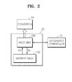
- FIG. 2 is a diagram illustrating a configuration of the battery system 20, according to an embodiment of the present invention.
- the battery system 20 includes a battery rack 100 and a rack battery management system (BMS) 200.
- BMS rack battery management system
- the battery rack 100 stores power supplied from an external source, that is, the power generating system 2 and/or the grid 3, and supplies stored power to the load 4 and/or the grid 3.
- the battery rack 100 may include a plurality of battery trays which will be described in detail with reference to FIG. 3 .
- the rack BMS 200 is connected to the battery rack 100 and may control charging and discharging operations of the battery rack 100.
- the rack BMS 200 may also perform various functions including overcharging protection, overdischarging protection, overcurrent protection, overvoltage protection, overheating protection, cell balancing control, and the like.
- the rack BMS 200 transmits a synchronizing signal Ss to the battery rack 100 and receives monitoring data Dm regarding a voltage, a current, a temperature, an amount of power remaining, lifespan, a charging state, etc. of a battery cell from at least one of tray BMSs 120-1 to 120-n included in the battery rack 100.
- the rack BMS 200 may apply the received monitoring data Dm to the integrated controller 15 and receive commands related to control of the battery rack 110 from the integrated controller 15.
- the rack BMS 200 may also charge power in the rack BMS 200 or discharge power stored in the rack BMS 200 under the control of the integrated controller 15.
- the rack BMS 200 may control charging/discharging current of the battery rack 100 under the control of the integrated controller 15.
- the charging/discharging current may be input/output to/from the charging/discharging current via the converter 14.
- FIG. 3 is a diagram illustrating a configuration of the battery rack 100, according to an embodiment of the present invention.
- the battery rack 100 may include a first battery tray 110-1 through an nth battery tray 110-n that are sub-units connected in series and/or in parallel.
- Each of the first battery tray 110-1 through the nth battery tray 110-n may include a plurality of battery cells as sub-units.
- One of various chargeable secondary batteries may be used as the battery cell.
- the various secondary batteries that may be used as the battery cell include a nickel-cadmium battery, a lead battery, a nickel metal hydrate (NiMH) battery, a lithium ion battery, a lithium polymer battery, or the like.
- the battery rack 100 may adjust output of the first battery tray 110-1 through the nth battery tray 110-n under the control of the rack BMS 200, and may output power by using a positive output terminal R+ and a negative output terminal R-.
- the battery rack 100 may include a first tray BMS 120-1 through an nth tray BMS 120-n that correspond to the first battery tray 110-1 through the nth battery tray 110-n, respectively.
- the first tray BMS 120-1 through the nth tray BMS 120-n receive synchronizing signals Ss from the rack BMS 200 and monitor voltages, currents, temperatures, and the like of the corresponding first battery tray 110-1 through nth battery tray 110-n.
- a result of the monitoring of the first tray BMS 120-1 through the nth tray BMS 120-n may be transmitted to the rack BMS 200.
- FIG. 4 is a diagram illustrating a structure of a kth battery tray 110-k and a kth tray BMS 120-k, according to an embodiment of the present invention.
- k is an integer that is greater than 0 and equal to or less than n.
- the kth battery tray 110-k indicates a structure of each of the first battery tray 110-1 through the nth battery tray 110-n
- the kth tray BMS 120-k indicates a structure of each of the first tray BMS 120-1 through the nth tray BMS 120-n.
- the kth battery tray 110-k includes one or more battery cells that are connected to each other in series or in parallel. As described above, the one or more battery cells may be embodied by using one of various chargeable secondary batteries.
- the kth tray BMS 120-k includes a cell balancing unit 410, a temperature measuring unit 420, an analog front end (AFE) 430, a cell balancing controller 440, and a micro controller unit (MCU) 450.
- AFE analog front end
- MCU micro controller unit
- the cell balancing unit 410 performs a cell balancing operation for removing a difference in voltage between the battery cells included in the kth battery tray 110-k.
- the cell balancing unit 410 may include a plurality of cell balancing resistors to adjust voltages of both ends of each battery cell.
- the temperature measuring unit 420 measures temperatures of the cell balancing resistors included in the cell balancing unit 410. According to the current embodiment, the temperature measuring unit 420 may measure only temperatures of some of the cell balancing resistors. Alternatively, the temperature measuring unit 420 may measure temperatures of all the cell balancing resistors.
- the temperature measuring unit 420 may be configured using, for example, a thermistor capable of measuring a temperature of a cell balancing resistor.
- the AFE 430 monitors a voltage, a current, a temperature, an amount of power remaining, lifespan, a charging state, or the like of the kth battery tray 110-k. Also, the AFE 430 analog-digital converts measured data and transmits the converted data to the MCU 450. According to the current embodiment, the AFE 430 may monitor the temperature of the cell balancing resistor that is measured by the temperature measuring unit 420, analog-digital convert the measured temperature, and transmit a temperature data TEMP to the MCU 450 and the cell balancing controller 440.
- the cell balancing controller 440 controls a cell balancing operation according to a difference in voltage between the battery cells included in the kth battery tray 110-k and a temperature of the cell balancing resistor of the cell balancing unit 410.
- the cell balancing controller 440 controls whether to perform cell balancing and a duty ratio of the cell balancing. For example, when a temperature of the cell balancing resistor is greater than a first reference temperature T1, the cell balancing controller 440 may reduce balancing current by adjusting a duty ratio of a cell balancing cycle. For example, when a temperature of the cell balancing resistor is equal to or greater than 60°C, the cell balancing controller 440 starts adjusting a duty ratio of a cell balancing cycle. At this time, the cell balancing controller 440 may reduce the duty ratio of about 5% whenever the temperature of the cell balancing resistor is increased by 1°C.
- the cell balancing controller 440 may stop cell balancing.
- the second reference temperature T2 is greater than the first reference temperature T1.
- the cell balancing controller 440 may stop cell balancing to prevent the cell balancing resistor from being destroyed. For example, when a temperature of the cell balancing resistor is equal to or greater than 70°C, a duty ratio of cell balancing may be set to 0% to stop the cell balancing.
- the cell balancing controller 440 may perform cell balancing only in a case where a difference in voltage between battery cells of the kth battery tray 110-k is equal to or greater than a reference voltage, and may not perform cell balancing in a case where a difference in voltage between battery cells of the kth battery tray 110-k is less than the reference voltage.
- unnecessary cell balancing may be prevented, thereby preventing heat from being generated due to the cell balancing and preventing the cell balancing resistor from being degraded.
- it may be determined whether the difference in voltage between the battery cells is equal to, greater than, or less than the reference voltage only in a case where the cell balancing resistor is fully charged.
- the cell balancing controller 440 may finish cell balancing. Also, when charging/discharging current is less than the reference current, the cell balancing controller 440 may finish cell balancing.
- the cell balancing controller 440 may operate according to a control signal applied from the MCU 450.
- the MCU 450 controls operations of the kth battery tray 110-k and the kth tray BMS 120-k.
- the MCU 450 controls an operation of the AFE 430 and collects monitoring data from the AFE 430. Also, the MCU 450 operates in synchronization with other battery trays and the rack BMS 200 according to a synchronizing signal Ss, provides monitoring data Dmk to the rack BMS 200, and receives a control signal from the rack BMS 200.
- the cell balancing controller 440 may be integrally formed with the MCU 450 or the AFE 430 as a part of the MCU 450 or the AFE 430.
- the MCU 450 is embedded in the tray BMS 120-k to perform a control operation.
- the MCU 450 may not be embedded in the tray BMS 120-k, and thus the tray BMS 120-k may be directly controlled by the rack BMS 200 or the integrated controller 15.
- the cell balancing may be controlled in units of a plurality of the battery trays 110-k.
- the tray BMS 120-k is directly controlled by the integrated controller 15, the cell balancing may be controlled in units of a plurality of the battery racks 100.
- FIG. 5 is a diagram illustrating structures of the kth battery tray 110-k and the kth tray BMS 120-k, according to an embodiment of the present invention.
- the cell balancing unit 410 may have a structure in which a plurality of cell balancing resistors R and a plurality of switching devices SW are connected to each other in series and one cell balancing resistor R and switching device SW pair is connected to each battery cell in parallel.
- a cell balancing operation for decreasing a difference in voltage between the battery cells is performed.
- Each of the switching devices SW may be switched on or off according to a balancing control signal BCON applied from the cell balancing controller 440.
- the balancing control signal BCON may have a cell balancing pulse for switching on the switching device SW, and the cell balancing pulse may be applied to a cell balancing section during an operation cycle of the kth tray BMS 120-k.
- FIG. 6 is a diagram illustrating waveforms of the balancing control signal BCO, according to an embodiment of the present invention.
- FIG. 6 illustrates waveforms of the balancing control signal BCON in cases where a temperature TEMP of the cell balancing resistor is 30°C, 65°C, and 75°C.
- the first reference temperature T1 is 60°C
- the second reference temperature T2 is 70°C.
- one operation cycle 1 CYCLE of the kth tray BMS 120-k may include a voltage measuring section, a temperature measuring section, and a cell balancing section.
- the temperature TEMP of the cell balancing resistor R is less than the first reference temperature T1, that is, when the temperature TEMP of the cell balancing resistor R is 30°C, the balancing control signal BCON has a cell balancing pulse having a duty ratio of 100% during the cell balancing section.
- a duty ratio of the cell balancing pulse during the cell balancing section is adjusted according to a temperature. For example, when a temperature of the cell balancing section is 65°C, the cell balancing pulse during the cell balancing section has a duty ratio of 50%. When the temperature TEMP of the cell balancing resistor R is greater than the second reference temperature T2, the cell balancing pulse has a duty ratio of 0%, and cell balancing is not performed during the corresponding cycle.
- FIG. 7 is a graph illustrating a duty ratio of the cell balancing pulse according to the temperature TEMP, according to an embodiment of the present invention.
- the cell balancing pulse has a constant duty ratio during a cell balancing section when the temperature TEMP of the cell balancing resistor R is equal to or less than the first reference temperature T1. As the temperature TEMP of the cell balancing resistor R is increased, the duty ratio of the cell balancing pulse between the first reference temperature T1 and the second reference temperature T2 is decreased.
- the temperature measuring unit 420 may have a plurality of thermometers TH, each of which are for respectively measuring a temperature of each of the cell balancing resistors R.
- a number of the thermometers TH may correspond to a number of the cell balancing resistors R so as to measure temperatures of all the cell balancing resistors R.
- a number of the thermometers TH may be less than that of the cell balancing resistors R so as to measure temperatures of only some of the cell balancing resistors R.
- the AFE 430 receives temperature detecting signals from the thermometers TH to generate temperature data TEMP, and transmits the temperature data TEMP to the cell balancing controller 440 and/or the MCU 450.
- the temperature data TEMP may be, for example, an average value of temperatures detected by the plurality of thermometers TH.
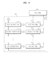
- FIG. 8 is a flowchart illustrating a method of balancing the battery cell, according to an embodiment of the present invention.
- a temperature of at least one cell balancing resistor R of the corresponding battery BMS 120-k is measured (S806).
- temperatures of all the cell balancing resistors R of the corresponding battery BMS 120-k may be measured, or alternatively, temperatures of only some of the cell balancing resistors R of the corresponding battery BMS 120-k may be measured. If the temperatures of the cell balancing resistors R are measured, a duty ratio of cell balancing is determined according to a temperature of the cell balancing resistor R (S808).
- a temperature of the cell balancing resistor R is less than the first reference temperature T1
- a duty ratio of a cell balancing pulse is not controlled, and if a temperature of the cell balancing resistor R is equal to or greater than the first reference temperature T1, a duty ratio of a cell balancing pulse is controlled according to the temperature of the cell balancing resistor R.
- a duty ratio of the cell balancing pulse is decreased.
- a duty ratio of the second reference temperature T2 may be set to 0% so as not to perform cell balancing. If a duty ratio of the cell balancing pulse is determined, cell balancing is performed according to the determined duty ratio (S810).
- the balancing controller 440 can provide a plurality of balancing control signals BCON.
Landscapes
- Engineering & Computer Science (AREA)
- Power Engineering (AREA)
- Secondary Cells (AREA)
- Charge And Discharge Circuits For Batteries Or The Like (AREA)
Applications Claiming Priority (2)
| Application Number | Priority Date | Filing Date | Title |
|---|---|---|---|
| US201161555919P | 2011-11-04 | 2011-11-04 | |
| US13/591,043 US9071056B2 (en) | 2011-11-04 | 2012-08-21 | Apparatus and method for managing battery cell, and energy storage system |
Publications (2)
| Publication Number | Publication Date |
|---|---|
| EP2590296A1 true EP2590296A1 (fr) | 2013-05-08 |
| EP2590296B1 EP2590296B1 (fr) | 2017-11-15 |
Family
ID=47008292
Family Applications (1)
| Application Number | Title | Priority Date | Filing Date |
|---|---|---|---|
| EP12182892.5A Active EP2590296B1 (fr) | 2011-11-04 | 2012-09-04 | Système de stockage d'énergie |
Country Status (3)
| Country | Link |
|---|---|
| US (1) | US9071056B2 (fr) |
| EP (1) | EP2590296B1 (fr) |
| CN (1) | CN103094989B (fr) |
Cited By (3)
| Publication number | Priority date | Publication date | Assignee | Title |
|---|---|---|---|---|
| CN106130067A (zh) * | 2016-07-15 | 2016-11-16 | 东莞理工学院 | 一种光伏发电系统及方法 |
| EP3396774A4 (fr) * | 2016-10-21 | 2019-03-13 | LG Chem, Ltd. | Procédé et système d'équilibrage d'élément de batterie efficace par commande de service |
| DE102021103070A1 (de) | 2021-02-10 | 2022-08-11 | Bayerische Motoren Werke Aktiengesellschaft | Elektrischer Energiespeicher für ein Kraftfahrzeug sowie Kraftfahrzeug |
Families Citing this family (30)
| Publication number | Priority date | Publication date | Assignee | Title |
|---|---|---|---|---|
| JP5918961B2 (ja) * | 2011-10-07 | 2016-05-18 | 株式会社ケーヒン | セルバランス制御装置 |
| US9318910B2 (en) * | 2012-09-06 | 2016-04-19 | Samsung Sdi Co., Ltd. | Cell balancing circuit and cell balancing method using the same |
| KR101459539B1 (ko) * | 2012-12-27 | 2014-11-07 | 현대모비스 주식회사 | 배터리 전압 균등화 장치 및 방법 |
| KR20150004035A (ko) * | 2013-07-02 | 2015-01-12 | 현대자동차주식회사 | 배터리셀 밸런싱 방법 및 시스템 |
| WO2015029568A1 (fr) * | 2013-08-28 | 2015-03-05 | 日本電気株式会社 | Procédé et programme permettant de commander un système de stockage d'énergie et une batterie rechargeable |
| JP5956966B2 (ja) * | 2013-09-06 | 2016-07-27 | 株式会社東芝 | 充電制御回路および充電制御システム |
| CN104638772B (zh) * | 2013-11-14 | 2018-01-19 | 国家电网公司 | 基于风功率预测的电池储能电站能量管理方法 |
| KR101631065B1 (ko) | 2013-12-03 | 2016-06-16 | 삼성에스디아이 주식회사 | 배터리 시스템 및 배터리 연결방법 |
| KR102165937B1 (ko) * | 2014-05-30 | 2020-10-14 | 삼성전자주식회사 | 배터리 관리 방법 및 장치 |
| KR20150137675A (ko) * | 2014-05-30 | 2015-12-09 | 삼성전자주식회사 | 배터리 관리 시스템의 셀 밸런싱 방법 및 장치 |
| US20160095226A1 (en) * | 2014-09-30 | 2016-03-31 | Thin Film Electronics Asa | Printed Timer Label |
| CN104505550B (zh) * | 2014-12-25 | 2017-01-18 | 宁德时代新能源科技股份有限公司 | 磷酸铁锂电池组的被动均衡方法及系统 |
| US9780567B2 (en) | 2015-02-19 | 2017-10-03 | Cummins Power Generation Ip, Inc. | Energy storage system |
| US9812866B2 (en) * | 2015-02-19 | 2017-11-07 | Cummins Power Generation Ip, Inc. | Energy storage system |
| EP3151405B1 (fr) * | 2015-09-30 | 2019-04-03 | Siemens Aktiengesellschaft | Circuit d'équilibrage des tensions aux bornes des condensateurs d'un circuit intermédiaire à courant continu |
| US10067203B2 (en) | 2015-10-09 | 2018-09-04 | General Electric Company | Energy storage solution for an MRI system |
| CN106655301A (zh) * | 2015-10-28 | 2017-05-10 | 中国科学院沈阳自动化研究所 | 一种适用于电动叉车的电源管理系统及方法 |
| DE102016107448A1 (de) | 2016-04-21 | 2017-10-26 | enfas GmbH | Energiespeichersystem |
| CN106026226B (zh) * | 2016-05-19 | 2019-07-09 | 东软集团股份有限公司 | 电池均衡方法、装置及电池系统 |
| KR102319241B1 (ko) * | 2017-01-03 | 2021-10-28 | 삼성에스디아이 주식회사 | 전압 검출 집적회로 및 이를 포함하는 배터리 관리 시스템 |
| CN116487794A (zh) | 2017-01-09 | 2023-07-25 | 米沃奇电动工具公司 | 用于向电气设备提供输出电力的设备 |
| CN108732448A (zh) * | 2017-04-24 | 2018-11-02 | 凹凸电子(武汉)有限公司 | 电池管理系统中的断线检测方法及断线解除检测方法 |
| KR102232116B1 (ko) * | 2017-06-13 | 2021-03-25 | 주식회사 엘지화학 | 밸런싱 저항을 이용한 과전압 방지 시스템 |
| WO2019145997A1 (fr) * | 2018-01-23 | 2019-08-01 | Tdk株式会社 | Système d'alimentation en courant continu |
| JP7112483B2 (ja) * | 2018-03-08 | 2022-08-03 | 三洋電機株式会社 | 管理装置、蓄電システム |
| CN112234266B (zh) * | 2018-03-30 | 2022-11-11 | 江苏罗思韦尔电气有限公司 | 一种均衡电池组系统的电池单体电压的装置 |
| EP3654510A1 (fr) * | 2018-11-19 | 2020-05-20 | Maschinenfabrik Reinhausen GmbH | Précharge d'un convertisseur multiniveaux modulairemodulaires à plusieurs niveaux |
| EP3654517B1 (fr) * | 2018-11-19 | 2021-06-02 | Maschinenfabrik Reinhausen GmbH | L'exploitation d'un convertisseur multiniveaux modulaire |
| CN110994746B (zh) * | 2019-12-31 | 2023-08-22 | 格力博(江苏)股份有限公司 | 电压均衡系统 |
| WO2023021267A1 (fr) * | 2021-08-20 | 2023-02-23 | Cirrus Logic International Semiconductor Limited | Équilibrage de cellules |
Citations (4)
| Publication number | Priority date | Publication date | Assignee | Title |
|---|---|---|---|---|
| US20030210017A1 (en) * | 2002-05-10 | 2003-11-13 | Toyota Jidosha Kabushiki Kaisha | Storage battery control apparatus and control method thereof |
| US20060022646A1 (en) * | 2004-07-28 | 2006-02-02 | Moore Stephen W | Method for battery cold-temperature warm-up mechanism using cell equilization hardware |
| US20100085009A1 (en) * | 2008-08-08 | 2010-04-08 | Kang Jung-Soo | Cell balancing apparatus and method |
| US20120133330A1 (en) * | 2010-11-26 | 2012-05-31 | Keihin Corporation | Cell balance control device |
Family Cites Families (9)
| Publication number | Priority date | Publication date | Assignee | Title |
|---|---|---|---|---|
| FR2740264B1 (fr) * | 1995-10-24 | 1997-12-05 | Em Microelectronic Marin Sa | Dispositif de gestion de batteries electriques |
| JP4843921B2 (ja) * | 2004-09-02 | 2011-12-21 | 日産自動車株式会社 | 組電池の容量調整装置及び組電池の容量調整方法 |
| KR100771803B1 (ko) | 2006-03-20 | 2007-10-30 | 현대모비스 주식회사 | 에이비에스장치용 솔레노이드밸브의 듀티 비 산출 방법 |
| KR101073277B1 (ko) | 2006-08-07 | 2011-10-12 | 주식회사 엘지화학 | 하이브리드 전기 자동차용 배터리 팩의 셀 밸런싱 방법 및이를 위한 장치 |
| JP2008236991A (ja) | 2007-03-23 | 2008-10-02 | Toshiba Corp | 電圧バランス回路、電池ユニットおよび電池ユニット制御方法 |
| JP5202918B2 (ja) * | 2007-10-03 | 2013-06-05 | 矢崎総業株式会社 | 電池電圧調整装置 |
| KR101091352B1 (ko) | 2008-05-28 | 2011-12-07 | 주식회사 엘지화학 | 과방전 방지 기능을 구비한 배터리 팩의 밸런싱 장치 |
| KR101084214B1 (ko) * | 2009-12-03 | 2011-11-18 | 삼성에스디아이 주식회사 | 계통 연계형 전력 저장 시스템 및 전력 저장 시스템 제어 방법 |
| KR101181822B1 (ko) | 2010-10-13 | 2012-09-11 | 삼성에스디아이 주식회사 | 배터리 관리 시스템 및 배터리 관리 방법, 이를 이용하는 전력 저장 장치 |
-
2012
- 2012-08-21 US US13/591,043 patent/US9071056B2/en active Active
- 2012-09-04 EP EP12182892.5A patent/EP2590296B1/fr active Active
- 2012-11-05 CN CN201210435843.5A patent/CN103094989B/zh active Active
Patent Citations (4)
| Publication number | Priority date | Publication date | Assignee | Title |
|---|---|---|---|---|
| US20030210017A1 (en) * | 2002-05-10 | 2003-11-13 | Toyota Jidosha Kabushiki Kaisha | Storage battery control apparatus and control method thereof |
| US20060022646A1 (en) * | 2004-07-28 | 2006-02-02 | Moore Stephen W | Method for battery cold-temperature warm-up mechanism using cell equilization hardware |
| US20100085009A1 (en) * | 2008-08-08 | 2010-04-08 | Kang Jung-Soo | Cell balancing apparatus and method |
| US20120133330A1 (en) * | 2010-11-26 | 2012-05-31 | Keihin Corporation | Cell balance control device |
Cited By (4)
| Publication number | Priority date | Publication date | Assignee | Title |
|---|---|---|---|---|
| CN106130067A (zh) * | 2016-07-15 | 2016-11-16 | 东莞理工学院 | 一种光伏发电系统及方法 |
| EP3396774A4 (fr) * | 2016-10-21 | 2019-03-13 | LG Chem, Ltd. | Procédé et système d'équilibrage d'élément de batterie efficace par commande de service |
| US10840711B2 (en) | 2016-10-21 | 2020-11-17 | Lg Chem, Ltd. | Method and system for effective battery cell balancing through duty control |
| DE102021103070A1 (de) | 2021-02-10 | 2022-08-11 | Bayerische Motoren Werke Aktiengesellschaft | Elektrischer Energiespeicher für ein Kraftfahrzeug sowie Kraftfahrzeug |
Also Published As
| Publication number | Publication date |
|---|---|
| CN103094989A (zh) | 2013-05-08 |
| US20130113280A1 (en) | 2013-05-09 |
| CN103094989B (zh) | 2016-06-22 |
| EP2590296B1 (fr) | 2017-11-15 |
| US9071056B2 (en) | 2015-06-30 |
Similar Documents
| Publication | Publication Date | Title |
|---|---|---|
| EP2590296B1 (fr) | Système de stockage d'énergie | |
| US9118191B2 (en) | Cell balancing method, cell balancing device, and energy storage system including the cell balancing device | |
| US10347952B2 (en) | Battery system | |
| US9401616B2 (en) | Battery pack, energy storage system including battery pack, and method of charging battery pack | |
| EP2884575B1 (fr) | Système de batterie et procédé de connexion de module de batterie à un support de batterie | |
| US9231407B2 (en) | Battery system, method of controlling the same, and energy storage system including the battery system | |
| KR101835585B1 (ko) | 배터리 팩, 배터리 팩의 셀 밸런싱 방법 및 이를 포함하는 에너지 저장 시스템 | |
| EP3148037B1 (fr) | Systeme de stockage d'energie | |
| CN104901324B (zh) | 储能系统及其控制方法 | |
| US8716892B2 (en) | Energy storage system and method of controlling the same | |
| KR101648889B1 (ko) | 배터리 팩 제어 장치 및 이를 포함하는 에너지 저장 시스템 | |
| KR101473324B1 (ko) | 배터리 관리 장치, 배터리 셀 밸런싱 방법, 및 전력 저장 시스템 | |
| EP2574075A2 (fr) | Système de batteries | |
| EP2629388A1 (fr) | Système de gestion d'énergie | |
| EP2325970A2 (fr) | Système de gestion d'énergie et système de stockage d'énergie raccordée au réseau incluant le système de gestion d'énergie | |
| US20120183813A1 (en) | Battery system and energy storage system including the same | |
| KR102415123B1 (ko) | 배터리 팩 및 이를 포함하는 에너지 저장 시스템 | |
| KR20150081731A (ko) | 배터리 팩, 배터리 팩을 포함하는 에너지 저장 시스템, 배터리 팩의 작동 방법 | |
| US20130130068A1 (en) | Battery system, method of controlling the battery system, and energy storage system including the same | |
| KR20130066283A (ko) | 배터리 시스템의 시뮬레이션 장치 | |
| KR20130062894A (ko) | 에너지 저장 시스템 및 그 제어방법 |
Legal Events
| Date | Code | Title | Description |
|---|---|---|---|
| PUAI | Public reference made under article 153(3) epc to a published international application that has entered the european phase |
Free format text: ORIGINAL CODE: 0009012 |
|
| AK | Designated contracting states |
Kind code of ref document: A1 Designated state(s): AL AT BE BG CH CY CZ DE DK EE ES FI FR GB GR HR HU IE IS IT LI LT LU LV MC MK MT NL NO PL PT RO RS SE SI SK SM TR |
|
| AX | Request for extension of the european patent |
Extension state: BA ME |
|
| 17P | Request for examination filed |
Effective date: 20131031 |
|
| RBV | Designated contracting states (corrected) |
Designated state(s): AL AT BE BG CH CY CZ DE DK EE ES FI FR GB GR HR HU IE IS IT LI LT LU LV MC MK MT NL NO PL PT RO RS SE SI SK SM TR |
|
| 17Q | First examination report despatched |
Effective date: 20140304 |
|
| GRAP | Despatch of communication of intention to grant a patent |
Free format text: ORIGINAL CODE: EPIDOSNIGR1 |
|
| INTG | Intention to grant announced |
Effective date: 20170602 |
|
| GRAS | Grant fee paid |
Free format text: ORIGINAL CODE: EPIDOSNIGR3 |
|
| GRAA | (expected) grant |
Free format text: ORIGINAL CODE: 0009210 |
|
| AK | Designated contracting states |
Kind code of ref document: B1 Designated state(s): AL AT BE BG CH CY CZ DE DK EE ES FI FR GB GR HR HU IE IS IT LI LT LU LV MC MK MT NL NO PL PT RO RS SE SI SK SM TR |
|
| REG | Reference to a national code |
Ref country code: CH Ref legal event code: EP Ref country code: GB Ref legal event code: FG4D Ref country code: AT Ref legal event code: REF Ref document number: 947163 Country of ref document: AT Kind code of ref document: T Effective date: 20171115 |
|
| REG | Reference to a national code |
Ref country code: IE Ref legal event code: FG4D |
|
| REG | Reference to a national code |
Ref country code: DE Ref legal event code: R096 Ref document number: 602012039719 Country of ref document: DE |
|
| REG | Reference to a national code |
Ref country code: NL Ref legal event code: MP Effective date: 20171115 |
|
| REG | Reference to a national code |
Ref country code: LT Ref legal event code: MG4D |
|
| REG | Reference to a national code |
Ref country code: AT Ref legal event code: MK05 Ref document number: 947163 Country of ref document: AT Kind code of ref document: T Effective date: 20171115 |
|
| PG25 | Lapsed in a contracting state [announced via postgrant information from national office to epo] |
Ref country code: NL Free format text: LAPSE BECAUSE OF FAILURE TO SUBMIT A TRANSLATION OF THE DESCRIPTION OR TO PAY THE FEE WITHIN THE PRESCRIBED TIME-LIMIT Effective date: 20171115 Ref country code: FI Free format text: LAPSE BECAUSE OF FAILURE TO SUBMIT A TRANSLATION OF THE DESCRIPTION OR TO PAY THE FEE WITHIN THE PRESCRIBED TIME-LIMIT Effective date: 20171115 Ref country code: SE Free format text: LAPSE BECAUSE OF FAILURE TO SUBMIT A TRANSLATION OF THE DESCRIPTION OR TO PAY THE FEE WITHIN THE PRESCRIBED TIME-LIMIT Effective date: 20171115 Ref country code: LT Free format text: LAPSE BECAUSE OF FAILURE TO SUBMIT A TRANSLATION OF THE DESCRIPTION OR TO PAY THE FEE WITHIN THE PRESCRIBED TIME-LIMIT Effective date: 20171115 Ref country code: ES Free format text: LAPSE BECAUSE OF FAILURE TO SUBMIT A TRANSLATION OF THE DESCRIPTION OR TO PAY THE FEE WITHIN THE PRESCRIBED TIME-LIMIT Effective date: 20171115 Ref country code: NO Free format text: LAPSE BECAUSE OF FAILURE TO SUBMIT A TRANSLATION OF THE DESCRIPTION OR TO PAY THE FEE WITHIN THE PRESCRIBED TIME-LIMIT Effective date: 20180215 |
|
| PG25 | Lapsed in a contracting state [announced via postgrant information from national office to epo] |
Ref country code: GR Free format text: LAPSE BECAUSE OF FAILURE TO SUBMIT A TRANSLATION OF THE DESCRIPTION OR TO PAY THE FEE WITHIN THE PRESCRIBED TIME-LIMIT Effective date: 20180216 Ref country code: BG Free format text: LAPSE BECAUSE OF FAILURE TO SUBMIT A TRANSLATION OF THE DESCRIPTION OR TO PAY THE FEE WITHIN THE PRESCRIBED TIME-LIMIT Effective date: 20180215 Ref country code: HR Free format text: LAPSE BECAUSE OF FAILURE TO SUBMIT A TRANSLATION OF THE DESCRIPTION OR TO PAY THE FEE WITHIN THE PRESCRIBED TIME-LIMIT Effective date: 20171115 Ref country code: LV Free format text: LAPSE BECAUSE OF FAILURE TO SUBMIT A TRANSLATION OF THE DESCRIPTION OR TO PAY THE FEE WITHIN THE PRESCRIBED TIME-LIMIT Effective date: 20171115 Ref country code: RS Free format text: LAPSE BECAUSE OF FAILURE TO SUBMIT A TRANSLATION OF THE DESCRIPTION OR TO PAY THE FEE WITHIN THE PRESCRIBED TIME-LIMIT Effective date: 20171115 Ref country code: AT Free format text: LAPSE BECAUSE OF FAILURE TO SUBMIT A TRANSLATION OF THE DESCRIPTION OR TO PAY THE FEE WITHIN THE PRESCRIBED TIME-LIMIT Effective date: 20171115 |
|
| PG25 | Lapsed in a contracting state [announced via postgrant information from national office to epo] |
Ref country code: SK Free format text: LAPSE BECAUSE OF FAILURE TO SUBMIT A TRANSLATION OF THE DESCRIPTION OR TO PAY THE FEE WITHIN THE PRESCRIBED TIME-LIMIT Effective date: 20171115 Ref country code: CZ Free format text: LAPSE BECAUSE OF FAILURE TO SUBMIT A TRANSLATION OF THE DESCRIPTION OR TO PAY THE FEE WITHIN THE PRESCRIBED TIME-LIMIT Effective date: 20171115 Ref country code: DK Free format text: LAPSE BECAUSE OF FAILURE TO SUBMIT A TRANSLATION OF THE DESCRIPTION OR TO PAY THE FEE WITHIN THE PRESCRIBED TIME-LIMIT Effective date: 20171115 Ref country code: CY Free format text: LAPSE BECAUSE OF FAILURE TO SUBMIT A TRANSLATION OF THE DESCRIPTION OR TO PAY THE FEE WITHIN THE PRESCRIBED TIME-LIMIT Effective date: 20171115 Ref country code: EE Free format text: LAPSE BECAUSE OF FAILURE TO SUBMIT A TRANSLATION OF THE DESCRIPTION OR TO PAY THE FEE WITHIN THE PRESCRIBED TIME-LIMIT Effective date: 20171115 |
|
| REG | Reference to a national code |
Ref country code: DE Ref legal event code: R097 Ref document number: 602012039719 Country of ref document: DE |
|
| REG | Reference to a national code |
Ref country code: FR Ref legal event code: PLFP Year of fee payment: 7 |
|
| PG25 | Lapsed in a contracting state [announced via postgrant information from national office to epo] |
Ref country code: SM Free format text: LAPSE BECAUSE OF FAILURE TO SUBMIT A TRANSLATION OF THE DESCRIPTION OR TO PAY THE FEE WITHIN THE PRESCRIBED TIME-LIMIT Effective date: 20171115 Ref country code: RO Free format text: LAPSE BECAUSE OF FAILURE TO SUBMIT A TRANSLATION OF THE DESCRIPTION OR TO PAY THE FEE WITHIN THE PRESCRIBED TIME-LIMIT Effective date: 20171115 Ref country code: PL Free format text: LAPSE BECAUSE OF FAILURE TO SUBMIT A TRANSLATION OF THE DESCRIPTION OR TO PAY THE FEE WITHIN THE PRESCRIBED TIME-LIMIT Effective date: 20171115 Ref country code: IT Free format text: LAPSE BECAUSE OF FAILURE TO SUBMIT A TRANSLATION OF THE DESCRIPTION OR TO PAY THE FEE WITHIN THE PRESCRIBED TIME-LIMIT Effective date: 20171115 |
|
| PLBE | No opposition filed within time limit |
Free format text: ORIGINAL CODE: 0009261 |
|
| STAA | Information on the status of an ep patent application or granted ep patent |
Free format text: STATUS: NO OPPOSITION FILED WITHIN TIME LIMIT |
|
| 26N | No opposition filed |
Effective date: 20180817 |
|
| PG25 | Lapsed in a contracting state [announced via postgrant information from national office to epo] |
Ref country code: SI Free format text: LAPSE BECAUSE OF FAILURE TO SUBMIT A TRANSLATION OF THE DESCRIPTION OR TO PAY THE FEE WITHIN THE PRESCRIBED TIME-LIMIT Effective date: 20171115 |
|
| PG25 | Lapsed in a contracting state [announced via postgrant information from national office to epo] |
Ref country code: MC Free format text: LAPSE BECAUSE OF FAILURE TO SUBMIT A TRANSLATION OF THE DESCRIPTION OR TO PAY THE FEE WITHIN THE PRESCRIBED TIME-LIMIT Effective date: 20171115 |
|
| REG | Reference to a national code |
Ref country code: CH Ref legal event code: PL |
|
| REG | Reference to a national code |
Ref country code: BE Ref legal event code: MM Effective date: 20180930 |
|
| REG | Reference to a national code |
Ref country code: IE Ref legal event code: MM4A |
|
| PG25 | Lapsed in a contracting state [announced via postgrant information from national office to epo] |
Ref country code: LU Free format text: LAPSE BECAUSE OF NON-PAYMENT OF DUE FEES Effective date: 20180904 |
|
| PG25 | Lapsed in a contracting state [announced via postgrant information from national office to epo] |
Ref country code: IE Free format text: LAPSE BECAUSE OF NON-PAYMENT OF DUE FEES Effective date: 20180904 |
|
| PG25 | Lapsed in a contracting state [announced via postgrant information from national office to epo] |
Ref country code: CH Free format text: LAPSE BECAUSE OF NON-PAYMENT OF DUE FEES Effective date: 20180930 Ref country code: LI Free format text: LAPSE BECAUSE OF NON-PAYMENT OF DUE FEES Effective date: 20180930 Ref country code: BE Free format text: LAPSE BECAUSE OF NON-PAYMENT OF DUE FEES Effective date: 20180930 |
|
| PG25 | Lapsed in a contracting state [announced via postgrant information from national office to epo] |
Ref country code: MT Free format text: LAPSE BECAUSE OF NON-PAYMENT OF DUE FEES Effective date: 20180904 |
|
| PG25 | Lapsed in a contracting state [announced via postgrant information from national office to epo] |
Ref country code: TR Free format text: LAPSE BECAUSE OF FAILURE TO SUBMIT A TRANSLATION OF THE DESCRIPTION OR TO PAY THE FEE WITHIN THE PRESCRIBED TIME-LIMIT Effective date: 20171115 |
|
| PG25 | Lapsed in a contracting state [announced via postgrant information from national office to epo] |
Ref country code: HU Free format text: LAPSE BECAUSE OF FAILURE TO SUBMIT A TRANSLATION OF THE DESCRIPTION OR TO PAY THE FEE WITHIN THE PRESCRIBED TIME-LIMIT; INVALID AB INITIO Effective date: 20120904 Ref country code: PT Free format text: LAPSE BECAUSE OF FAILURE TO SUBMIT A TRANSLATION OF THE DESCRIPTION OR TO PAY THE FEE WITHIN THE PRESCRIBED TIME-LIMIT Effective date: 20171115 |
|
| PG25 | Lapsed in a contracting state [announced via postgrant information from national office to epo] |
Ref country code: MK Free format text: LAPSE BECAUSE OF NON-PAYMENT OF DUE FEES Effective date: 20171115 |
|
| PG25 | Lapsed in a contracting state [announced via postgrant information from national office to epo] |
Ref country code: AL Free format text: LAPSE BECAUSE OF FAILURE TO SUBMIT A TRANSLATION OF THE DESCRIPTION OR TO PAY THE FEE WITHIN THE PRESCRIBED TIME-LIMIT Effective date: 20171115 Ref country code: IS Free format text: LAPSE BECAUSE OF FAILURE TO SUBMIT A TRANSLATION OF THE DESCRIPTION OR TO PAY THE FEE WITHIN THE PRESCRIBED TIME-LIMIT Effective date: 20180315 |
|
| P01 | Opt-out of the competence of the unified patent court (upc) registered |
Effective date: 20230528 |
|
| PGFP | Annual fee paid to national office [announced via postgrant information from national office to epo] |
Ref country code: GB Payment date: 20230824 Year of fee payment: 12 |
|
| PGFP | Annual fee paid to national office [announced via postgrant information from national office to epo] |
Ref country code: FR Payment date: 20230911 Year of fee payment: 12 Ref country code: DE Payment date: 20230830 Year of fee payment: 12 |