EP2589901B1 - Refrigeration cycle apparatus and hot water generator - Google Patents
Refrigeration cycle apparatus and hot water generator Download PDFInfo
- Publication number
- EP2589901B1 EP2589901B1 EP12191093.9A EP12191093A EP2589901B1 EP 2589901 B1 EP2589901 B1 EP 2589901B1 EP 12191093 A EP12191093 A EP 12191093A EP 2589901 B1 EP2589901 B1 EP 2589901B1
- Authority
- EP
- European Patent Office
- Prior art keywords
- compressor
- refrigerant
- temperature
- superheat degree
- refrigeration cycle
- Prior art date
- Legal status (The legal status is an assumption and is not a legal conclusion. Google has not performed a legal analysis and makes no representation as to the accuracy of the status listed.)
- Active
Links
- 238000005057 refrigeration Methods 0.000 title claims description 76
- XLYOFNOQVPJJNP-UHFFFAOYSA-N water Substances O XLYOFNOQVPJJNP-UHFFFAOYSA-N 0.000 title claims description 29
- 239000003507 refrigerant Substances 0.000 claims description 126
- 238000010438 heat treatment Methods 0.000 claims description 52
- 239000007788 liquid Substances 0.000 claims description 28
- 230000002528 anti-freeze Effects 0.000 claims description 6
- 239000003921 oil Substances 0.000 description 34
- 238000009833 condensation Methods 0.000 description 10
- 230000005494 condensation Effects 0.000 description 10
- 238000010586 diagram Methods 0.000 description 7
- 230000006835 compression Effects 0.000 description 6
- 238000007906 compression Methods 0.000 description 6
- 238000007796 conventional method Methods 0.000 description 3
- 239000010721 machine oil Substances 0.000 description 3
- 238000001514 detection method Methods 0.000 description 2
- 230000002708 enhancing effect Effects 0.000 description 2
- 238000000034 method Methods 0.000 description 2
- 230000000630 rising effect Effects 0.000 description 2
- 238000010257 thawing Methods 0.000 description 2
- 230000000694 effects Effects 0.000 description 1
- 238000005461 lubrication Methods 0.000 description 1
- 229920006395 saturated elastomer Polymers 0.000 description 1
- 238000009834 vaporization Methods 0.000 description 1
- 230000008016 vaporization Effects 0.000 description 1
Images


Classifications
-
- F—MECHANICAL ENGINEERING; LIGHTING; HEATING; WEAPONS; BLASTING
- F25—REFRIGERATION OR COOLING; COMBINED HEATING AND REFRIGERATION SYSTEMS; HEAT PUMP SYSTEMS; MANUFACTURE OR STORAGE OF ICE; LIQUEFACTION SOLIDIFICATION OF GASES
- F25B—REFRIGERATION MACHINES, PLANTS OR SYSTEMS; COMBINED HEATING AND REFRIGERATION SYSTEMS; HEAT PUMP SYSTEMS
- F25B49/00—Arrangement or mounting of control or safety devices
- F25B49/02—Arrangement or mounting of control or safety devices for compression type machines, plants or systems
-
- F—MECHANICAL ENGINEERING; LIGHTING; HEATING; WEAPONS; BLASTING
- F25—REFRIGERATION OR COOLING; COMBINED HEATING AND REFRIGERATION SYSTEMS; HEAT PUMP SYSTEMS; MANUFACTURE OR STORAGE OF ICE; LIQUEFACTION SOLIDIFICATION OF GASES
- F25B—REFRIGERATION MACHINES, PLANTS OR SYSTEMS; COMBINED HEATING AND REFRIGERATION SYSTEMS; HEAT PUMP SYSTEMS
- F25B13/00—Compression machines, plants or systems, with reversible cycle
-
- F—MECHANICAL ENGINEERING; LIGHTING; HEATING; WEAPONS; BLASTING
- F25—REFRIGERATION OR COOLING; COMBINED HEATING AND REFRIGERATION SYSTEMS; HEAT PUMP SYSTEMS; MANUFACTURE OR STORAGE OF ICE; LIQUEFACTION SOLIDIFICATION OF GASES
- F25B—REFRIGERATION MACHINES, PLANTS OR SYSTEMS; COMBINED HEATING AND REFRIGERATION SYSTEMS; HEAT PUMP SYSTEMS
- F25B2339/00—Details of evaporators; Details of condensers
- F25B2339/04—Details of condensers
- F25B2339/047—Water-cooled condensers
-
- F—MECHANICAL ENGINEERING; LIGHTING; HEATING; WEAPONS; BLASTING
- F25—REFRIGERATION OR COOLING; COMBINED HEATING AND REFRIGERATION SYSTEMS; HEAT PUMP SYSTEMS; MANUFACTURE OR STORAGE OF ICE; LIQUEFACTION SOLIDIFICATION OF GASES
- F25B—REFRIGERATION MACHINES, PLANTS OR SYSTEMS; COMBINED HEATING AND REFRIGERATION SYSTEMS; HEAT PUMP SYSTEMS
- F25B2400/00—General features or devices for refrigeration machines, plants or systems, combined heating and refrigeration systems or heat-pump systems, i.e. not limited to a particular subgroup of F25B
- F25B2400/01—Heaters
-
- F—MECHANICAL ENGINEERING; LIGHTING; HEATING; WEAPONS; BLASTING
- F25—REFRIGERATION OR COOLING; COMBINED HEATING AND REFRIGERATION SYSTEMS; HEAT PUMP SYSTEMS; MANUFACTURE OR STORAGE OF ICE; LIQUEFACTION SOLIDIFICATION OF GASES
- F25B—REFRIGERATION MACHINES, PLANTS OR SYSTEMS; COMBINED HEATING AND REFRIGERATION SYSTEMS; HEAT PUMP SYSTEMS
- F25B2500/00—Problems to be solved
- F25B2500/16—Lubrication
-
- F—MECHANICAL ENGINEERING; LIGHTING; HEATING; WEAPONS; BLASTING
- F25—REFRIGERATION OR COOLING; COMBINED HEATING AND REFRIGERATION SYSTEMS; HEAT PUMP SYSTEMS; MANUFACTURE OR STORAGE OF ICE; LIQUEFACTION SOLIDIFICATION OF GASES
- F25B—REFRIGERATION MACHINES, PLANTS OR SYSTEMS; COMBINED HEATING AND REFRIGERATION SYSTEMS; HEAT PUMP SYSTEMS
- F25B2500/00—Problems to be solved
- F25B2500/26—Problems to be solved characterised by the startup of the refrigeration cycle
-
- F—MECHANICAL ENGINEERING; LIGHTING; HEATING; WEAPONS; BLASTING
- F25—REFRIGERATION OR COOLING; COMBINED HEATING AND REFRIGERATION SYSTEMS; HEAT PUMP SYSTEMS; MANUFACTURE OR STORAGE OF ICE; LIQUEFACTION SOLIDIFICATION OF GASES
- F25B—REFRIGERATION MACHINES, PLANTS OR SYSTEMS; COMBINED HEATING AND REFRIGERATION SYSTEMS; HEAT PUMP SYSTEMS
- F25B2500/00—Problems to be solved
- F25B2500/31—Low ambient temperatures
-
- F—MECHANICAL ENGINEERING; LIGHTING; HEATING; WEAPONS; BLASTING
- F25—REFRIGERATION OR COOLING; COMBINED HEATING AND REFRIGERATION SYSTEMS; HEAT PUMP SYSTEMS; MANUFACTURE OR STORAGE OF ICE; LIQUEFACTION SOLIDIFICATION OF GASES
- F25B—REFRIGERATION MACHINES, PLANTS OR SYSTEMS; COMBINED HEATING AND REFRIGERATION SYSTEMS; HEAT PUMP SYSTEMS
- F25B2600/00—Control issues
- F25B2600/02—Compressor control
- F25B2600/025—Compressor control by controlling speed
- F25B2600/0253—Compressor control by controlling speed with variable speed
-
- F—MECHANICAL ENGINEERING; LIGHTING; HEATING; WEAPONS; BLASTING
- F25—REFRIGERATION OR COOLING; COMBINED HEATING AND REFRIGERATION SYSTEMS; HEAT PUMP SYSTEMS; MANUFACTURE OR STORAGE OF ICE; LIQUEFACTION SOLIDIFICATION OF GASES
- F25B—REFRIGERATION MACHINES, PLANTS OR SYSTEMS; COMBINED HEATING AND REFRIGERATION SYSTEMS; HEAT PUMP SYSTEMS
- F25B2600/00—Control issues
- F25B2600/25—Control of valves
- F25B2600/2513—Expansion valves
-
- F—MECHANICAL ENGINEERING; LIGHTING; HEATING; WEAPONS; BLASTING
- F25—REFRIGERATION OR COOLING; COMBINED HEATING AND REFRIGERATION SYSTEMS; HEAT PUMP SYSTEMS; MANUFACTURE OR STORAGE OF ICE; LIQUEFACTION SOLIDIFICATION OF GASES
- F25B—REFRIGERATION MACHINES, PLANTS OR SYSTEMS; COMBINED HEATING AND REFRIGERATION SYSTEMS; HEAT PUMP SYSTEMS
- F25B2700/00—Sensing or detecting of parameters; Sensors therefor
- F25B2700/19—Pressures
- F25B2700/193—Pressures of the compressor
- F25B2700/1931—Discharge pressures
-
- F—MECHANICAL ENGINEERING; LIGHTING; HEATING; WEAPONS; BLASTING
- F25—REFRIGERATION OR COOLING; COMBINED HEATING AND REFRIGERATION SYSTEMS; HEAT PUMP SYSTEMS; MANUFACTURE OR STORAGE OF ICE; LIQUEFACTION SOLIDIFICATION OF GASES
- F25B—REFRIGERATION MACHINES, PLANTS OR SYSTEMS; COMBINED HEATING AND REFRIGERATION SYSTEMS; HEAT PUMP SYSTEMS
- F25B2700/00—Sensing or detecting of parameters; Sensors therefor
- F25B2700/21—Temperatures
- F25B2700/2115—Temperatures of a compressor or the drive means therefor
- F25B2700/21152—Temperatures of a compressor or the drive means therefor at the discharge side of the compressor
-
- F—MECHANICAL ENGINEERING; LIGHTING; HEATING; WEAPONS; BLASTING
- F25—REFRIGERATION OR COOLING; COMBINED HEATING AND REFRIGERATION SYSTEMS; HEAT PUMP SYSTEMS; MANUFACTURE OR STORAGE OF ICE; LIQUEFACTION SOLIDIFICATION OF GASES
- F25B—REFRIGERATION MACHINES, PLANTS OR SYSTEMS; COMBINED HEATING AND REFRIGERATION SYSTEMS; HEAT PUMP SYSTEMS
- F25B2700/00—Sensing or detecting of parameters; Sensors therefor
- F25B2700/21—Temperatures
- F25B2700/2116—Temperatures of a condenser
- F25B2700/21161—Temperatures of a condenser of the fluid heated by the condenser
-
- F—MECHANICAL ENGINEERING; LIGHTING; HEATING; WEAPONS; BLASTING
- F25—REFRIGERATION OR COOLING; COMBINED HEATING AND REFRIGERATION SYSTEMS; HEAT PUMP SYSTEMS; MANUFACTURE OR STORAGE OF ICE; LIQUEFACTION SOLIDIFICATION OF GASES
- F25B—REFRIGERATION MACHINES, PLANTS OR SYSTEMS; COMBINED HEATING AND REFRIGERATION SYSTEMS; HEAT PUMP SYSTEMS
- F25B2700/00—Sensing or detecting of parameters; Sensors therefor
- F25B2700/21—Temperatures
- F25B2700/2117—Temperatures of an evaporator
- F25B2700/21175—Temperatures of an evaporator of the refrigerant at the outlet of the evaporator
-
- Y—GENERAL TAGGING OF NEW TECHNOLOGICAL DEVELOPMENTS; GENERAL TAGGING OF CROSS-SECTIONAL TECHNOLOGIES SPANNING OVER SEVERAL SECTIONS OF THE IPC; TECHNICAL SUBJECTS COVERED BY FORMER USPC CROSS-REFERENCE ART COLLECTIONS [XRACs] AND DIGESTS
- Y02—TECHNOLOGIES OR APPLICATIONS FOR MITIGATION OR ADAPTATION AGAINST CLIMATE CHANGE
- Y02B—CLIMATE CHANGE MITIGATION TECHNOLOGIES RELATED TO BUILDINGS, e.g. HOUSING, HOUSE APPLIANCES OR RELATED END-USER APPLICATIONS
- Y02B30/00—Energy efficient heating, ventilation or air conditioning [HVAC]
- Y02B30/70—Efficient control or regulation technologies, e.g. for control of refrigerant flow, motor or heating
Definitions
- the present invention relates to a refrigeration cycle apparatus and a hot water generator using the refrigeration cycle apparatus.
- a conventional refrigeration cycle apparatus of this kind includes a heating device for heating a compressor when a predetermined condition is not satisfied so that reliability of the compressor is not deteriorated when the refrigeration cycle apparatus is started in a state where an ambient temperature is low (see patent document 1 for example).
- Figs. 6 show a conventional refrigeration cycle apparatus described in patent document 1.
- a compressor 111, a radiator 112 which functions as a condenser and which heats a flowing heat medium, an expansion valve 113 and an evaporator 114 are annularly and sequentially connected, through refrigerant pipes, to a refrigerant circuit 110 through which a refrigerant is circulated.
- the compressor 111 is provided with a heating device 310 which heats the compressor 111, and a temperature sensor 151 which detects a refrigeration oil temperature (compressor shell temperature) Td of the compressor 111.
- the compressor 111 is further provided with a control unit 141.
- the temperature sensor 151 provided in the compressor 111 detects a compressor shell temperature Td.
- the control unit 141 determines that liquid refrigerant and refrigeration oil remain in a shell bottom of the compressor 111 when the compressor 111 is started, and refrigeration oil can be supplied to a compressing mechanism or a bearing. Hence, the control unit 141 does not operate the heating device 151.
- the control unit 141 determines that viscosities of the liquid refrigerant and refrigeration oil in the compressor 111 become high and flowability is deteriorated, and lubrication failure is generated in the compressing mechanism or the bearing. Hence, the control unit 141 operates the heating device 151. According to this configuration, the refrigeration oil is supplied to the compressing mechanism or the bearing, and reliability of the compressor 111 is secured.
- US patent application 2002/0129612 A1 discloses a refrigeration cycle according to the preamble of claim 1 having a residual refrigerant, which is designed that the refrigerating machine oil does not stagnate in the refrigeration cycle after flowing out from the compressor even if the refrigerating machine oil is weakly soluble in a refrigerant.
- a control section is provided for controlling saturated oil solubility in a liquid refrigerant in the refrigeration cycle.
- the control section includes a receiver and first and second flow regulators which are placed before and after, respectively, the receiver.
- a residual liquid refrigerant obtaining in the circulation of a refrigerant is reserved in the receiver at a high temperature so that the weakly soluble refrigerating machine oil is prevented from separating.
- the present invention has been accomplished to solve the conventional problem, and it is an object of the invention to provide a refrigeration cycle apparatus capable of reliably supplying a refrigeration oil to a compressing mechanism or a bearing, and capable of enhancing reliability of a compressor.
- the present invention provides a refrigeration cycle apparatus comprising: a refrigerant circuit which is formed by annularly and sequentially connecting a compressor, a radiator, expansion means and an evaporator to one another through refrigerant pipes, and through which a refrigerant is circulated; a first temperature sensor which detects a temperature of the compressor or a temperature of the refrigerant pipe through which the compressor and the radiator are connected to each other; a second temperature sensor which detects a temperature of a heat medium which is a to-be heated body of the radiator; a heating device which heats the compressor; and a control unit; characterized in that the control unit operates the heating device when the temperature detected by the second temperature sensor becomes higher than the temperature detected by the first temperature sensor by a predetermined temperature difference or more.
- the heating device when a compressor shell temperature of a high pressure shell type compressor is low and a temperature of a heat medium flowing through the radiator is high, the heating device is operated and if the compressor shell temperature rises and becomes equal to or higher than a saturation temperature by operating the heating device, an overheated gas refrigerant discharged from the compression chamber is less prone to be condensed in the compressor, and the overheated gas refrigerant can be discharged from the discharge pipe of the compressor as a gas refrigerant which keeps the superheat degree.
- a refrigeration cycle apparatus capable of reliably supplying a refrigeration oil to a compressing mechanism or a bearing, and capable of enhancing reliability of a compressor.
- a first aspect of the invention provides a refrigeration cycle apparatus comprising: a refrigerant circuit which is formed by annularly and sequentially connecting a compressor, a radiator, expansion means and an evaporator to one another through refrigerant pipes, and through which a refrigerant is circulated; a first temperature sensor which detects a temperature of the compressor or a temperature of the refrigerant pipe through which the compressor and the radiator are connected to each other; a second temperature sensor which detects a temperature of a heat medium which is a to-be heated body of the radiator; a heating device which heats the compressor; and a control unit; characterized in that the control unit operates the heating device when the temperature detected by the second temperature sensor becomes higher than the temperature detected by the first temperature sensor by a predetermined temperature difference or more.
- an overheated gas refrigerant discharged from the compression chamber is less prone to be condensed in the compressor, and the overheated gas refrigerant can be discharged from the discharge pipe of the compressor as a gas refrigerant which keeps the superheat degree.
- the refrigeration cycle apparatus further includes first superheat degree detecting means which detects a superheat degree of the refrigerant discharged from the compressor, and the control unit controls number of rotations of the compressor such that a circulation amount of the refrigerant becomes equal to or smaller than a predetermined value until the superheat degree detected by the first superheat degree detecting means becomes equal to a predetermined value.
- the refrigeration cycle apparatus is operated in a state where a circulation amount of the refrigerant is small until the refrigerant is brought into a superheated state where it can be determined that condensation of the discharge refrigerant in the compressor shell is completed.
- an amount of the refrigerant itself discharged from the compressor is reduced, and a content rate of refrigeration oil which is mixed into the discharge refrigerant and which flows out from the compressor is reduced.
- the refrigeration cycle apparatus further includes second superheat degree detecting means which detects a superheat degree of the refrigerant flowing out from the evaporator, and the control unit controls an opening degree of the expansion means such that the superheat degree detected by the second superheat degree detecting means becomes equal to a predetermined value.
- the expansion vale is controlled such that a superheat degree at the evaporator outlet in the refrigeration cycle becomes equal to a predetermined superheat degree (high superheat degree such as 10 deg for example), the refrigerant sucked into the compressor is brought into the superheated state and heats the compressor.
- a superheat degree at the evaporator outlet in the refrigeration cycle becomes equal to a predetermined superheat degree (high superheat degree such as 10 deg for example)
- a fourth aspect of the invention provides a hot water generator using the refrigeration cycle apparatus according to any one of the first to third aspects, the heat medium is water or antifreeze liquid, and the water or the antifreeze liquid heated by the radiator is utilized for supplying hot water and/or heating.
- the heat medium can wisely be used for a heating device (floor heating system, panel heater utilizing natural convection, and fan-convector utilizing forced convection) and a water heater.
- Fig. 1 is a schematic block diagram of a hot water generator 1A according to a first embodiment of the present invention.
- the hot water generator 1A includes a refrigeration cycle apparatus 1B and a heat medium circuit 3.
- the refrigeration cycle apparatus 1B includes a refrigerant circuit 2 through which a refrigerant is circulated.
- a refrigerant it is possible to use a zeotropic mixed refrigerant such as R407C, a pseudo-azeotropic mixed refrigerant such as R410A, and a single refrigerant such as R32.
- a high pressure shell type compressor 21, a radiator 22, expansion means (expansion vale) 23, and an evaporator 24 are annularly and sequentially connected to the refrigerant circuit 2 through refrigerant pipes 26.
- a four-way valve 25 is connected to the refrigerant circuit 2. The four-way valve 25 switches the refrigerant pipe 26 connected to a discharge port of the compressor 21 to the radiator 22 or the evaporator 24, and switches the refrigerant pipe 26 connected to a suction port of the compressor 21 to the evaporator 24 or the radiator 22.
- the four-way valve 25 switches between a heating operation for heating a heat medium of the heat medium circuit 3 utilizing condensation latent heat of a refrigerant in the radiator 22 and a defrosting operation for defrosting frost adhering to the evaporator 24.
- a heating device 31 heats the compressor 21 by instructions from a control unit 4.
- the refrigeration cycle apparatus 1B further includes a first temperature sensor 51 which detects a temperature of the compressor 21 or a temperature of the refrigerant pipe 26 extending from the compressor 21 to the radiator 22, first superheat degree detecting means 61 which detects a superheat degree of a refrigerant discharged from the compressor 21, and second superheat degree detecting means 62 which detects a superheat degree of a refrigerant flowing out from the evaporator 24.
- the refrigeration cycle apparatus 1B constitutes a hot water generator which utilizes a high temperature heat medium (hot water) generated by the radiator 22 for supplying hot water or heating.
- the radiator 22 heat-exchanges between a refrigerant and a heat medium.
- the heat medium circuit 3 includes the radiator 22 and a second temperature sensor 52 which detects a temperature of a heat medium.
- the second temperature sensor 52 detects a temperature of a heat medium before it is introduced into the radiator 22.
- FIG. 1 flowing directions of a refrigerant and a heat medium when the heating operation for heating the heat medium is carried out in the radiator 22 are shown by arrows.
- a high pressure refrigerant discharged from the compressor 21 flows into the radiator 22 through the four-way valve 25.
- the high pressure refrigerant radiates condensation heat, and the refrigerant is cooled, liquefied and condensed.
- the cooled high pressure liquid refrigerant flows out from the radiator 22.
- the high pressure liquid refrigerant which flows out from the radiator 22 is decompressed by the expansion means 23 and expanded and then, the liquid refrigerant flows into the evaporator 24.
- the low pressure two-phase refrigerant which flows into the evaporator 24 absorbs vaporization heat from air and evaporates, the refrigerant becomes the low pressure two-phase refrigerant or a superheated refrigerant, and flows out from the evaporator 24.
- the low pressure refrigerant which flows out from the evaporator 24 passes through the four-way valve 25 and is sucked into the compressor 21.
- the low temperature heat medium which flows into the radiator 22 heat-exchanges with a refrigerant becomes a high temperature heat medium and flows out from the radiator 22.
- the high temperature heat medium which flows out is utilized for the heating device (floor heating system, panel heater utilizing natural convection, and fan-convector utilizing forced convection) or the water heater, radiates heat and then, the heat medium flows into the radiator 22 again and is circulates through the heat medium circuit 3.
- the control unit 4 controls the heating device 31 using detection values detected by the first temperature sensor 51 and the second temperature sensor 52.
- the control unit 4 controls the number of rotations of the compressor 21, the switching operation of the four-way valve 25 and an opening degree of the expansion means 23 using detection values of the first superheat degree detecting means 61 and the second superheat degree detecting means 62.
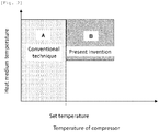
- Fig. 2 shows contents of control of the heating device.
- the control unit 4 utilizes only a temperature detected by the first temperature sensor 51, and operates the heating device 31. That is, when a temperature (shell temperature) of the compressor 21 detected by the first temperature sensor 51 is lower than a set temperature (region A in Fig. 2 ), the control unit 4 operates the heating device 31, and when the shell temperature is equal to or higher than the set temperature, the control unit 4 stops the heating device 31, both irrespective of the heat medium temperature as shown in Fig. 2 .
- the set temperature is set to winter outside air temperature, e.g., about 10°C.
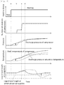
- Fig. 3 shows a case where the heating operation is started in a state where a temperature of a heat medium flowing through the radiator 22 is higher than a shell temperature of the high pressure shell type compressor 21 and a temperature difference between the heat medium temperature and the shell temperature is great.
- An example this state is a state where the heating operation for heating a heat medium to a high temperature is carried out by the refrigeration cycle apparatus 1B, and after a thermostat is turned OFF and the compressor 21 is stopped, a shell temperature of the compressor 21 is lowered to a temperature in the vicinity of an ambient temperature of the compressor 21 and a long time is elapsed.
- the compressor 21 is started (a in Fig. 3 )
- a pressure of the refrigerant abruptly rises and a discharge pressure saturation temperature of the refrigerant becomes high.
- the compressor 21 is heated by a compressing operation, but the shell temperature of the compressor 21 gradually rises from the temperature in the vicinity of the ambient temperature of the compressor 21 due to heat capacity of the compressor 21 itself. At this time, like sections a to b in Fig. 3 , the shell temperature of the compressor 21 becomes lower than the saturation temperature of the discharge pressure, and the overheated gas refrigerant discharged from the compression chamber is condensed in the compressor 21.
- the refrigerant which becomes the liquid refrigerant by the condensation is mixed with refrigeration oil in the compressor 21, a liquid level (refrigeration oil + liquid refrigerant) of the compressor 21 rises and a large amount of the refrigerant is discharged out from the discharge pipe of the compressor 21. Thereafter, if the shell temperature of the compressor 21 becomes higher than the saturation temperature of the discharge pressure as shown by b and thereafter in Fig. 3 , since a refrigerant component in the refrigeration oil evaporates, the liquid level is lowered at a dash, and the liquid level becomes lower than a liquid level height at which oil can be supplied.
- the heating device 31 when the shell temperature is equal to or higher than the set temperature, the heating device 31 does not operate.
- the heating device 31 when the temperature of the heat medium becomes higher than the shell temperature of the compressor 21 by a predetermined temperature difference or more (region B in Fig. 2 ), the heating device 31 is operated and after predetermined time is elapsed, the compressor 21 is started. At that time, the number of rotations of the compressor 21 is reduced and the compressor 21 is operated so that a circulation amount of the refrigerant becomes smaller than a predetermined circulation amount.
- the control unit 4 controls such that a superheat degree of a refrigerant flowing out from the evaporator 24 becomes equal to a predetermined superheat degree.
- the heating device 31 is operated (a in Fig. 4 )
- the shell temperature rises (b in Fig. 4 )
- a discharge pressure saturation temperature of the compressor 21 becomes high.
- the compressor 21 is operated with the low number of rotations to suppress the circulation amount, the overheated gas refrigerant discharged from the compression chamber of the compressor 21 is less prone to be condensed in the compressor 21.
- the compressor 21 is operated in a state where the circulation amount of the refrigerant is small, an amount of a refrigerant itself which is discharged from the compressor 21 is reduced, the refrigerant is mixed with a discharge refrigerant, and a content rate of refrigeration oil flowing out from the compressor 21 is reduced.
- the sucked refrigerant in the compressor 21 is brought into a superheated state and heats the compressor 21.
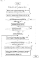
- Control of the control unit 4 will be described below in detail with reference to a flowchart shown in Fig. 5 .
- control unit 4 receives instructions for starting a heating operation which are input through a remote control, and carries out the heating operation (step 1 (S1)).
- the second temperature sensor 52 detects a heat medium temperature Tw
- the first temperature sensor 51 detects a compressor shell temperature Td (step 2)
- control unit 4 compares the temperature difference Ta and a predetermined temperature difference Tx with each other, and determines whether the temperature difference Ta is equal to or greater than the temperature difference Tx (step 4).
- the heating device 31 is operated (step 5) .
- control unit 4 determines whether predetermined time t1 is elapsed after the heating device 31 is operated (step 6). When the predetermined time t1 is not elapsed (NO in step 6), the current state is maintained. When the predetermined time t1 is elapsed (YES in step 6), the compressor 21 is started (step 7).
- control unit 4 controls such that the first superheat degree detecting means 61 detects a discharge superheat degree SHd and the second superheat degree detecting means 62 detects a suction superheat degree SHe (step 8).
- the discharge superheat degree SHd and a predetermined first superheat degree SHx are compared with each other, and it is determined whether the discharge superheat degree SHd is equal to or smaller than a first superheat degree SHx (step 9).
- the discharge superheat degree SHd is equal to or smaller than the predetermined first superheat degree SHx (YES in step 9)
- the number of rotations of the compressor 21 is reduced so that the circulation amount of a refrigerant in the refrigeration cycle 2 becomes equal to or smaller than a predetermined value and the compressor is operated (step 10), and an opening degree of the expansion means 23 is adjusted so that the suction superheat degree SHe becomes equal to a predetermined second superheat degree SHy (step 11). Then, the procedure is returned to step 8.
- the refrigeration cycle apparatus of the embodiment includes the heating device 31 which heats the compressor 21, the first temperature sensor 51 which detects a temperature of the compressor 21 or a temperature of the refrigerant pipe 26 reaching the radiator 22, the second temperature sensor 52 which detects a temperature of a heat medium in the heat medium circuit 3, and the control unit 4.
- the control unit 4 controls such that the heating device 31 is operated and after the predetermined time t1 is elapsed, the compressor 21 is started.
- the heating device 31 of the compressor 21 is operated. According to this, if the shell temperature rises and becomes higher than the saturation temperature, the overheated gas refrigerant discharged from the compression chamber of the compressor 21 is less prone to be condensed in the compressor 21, and gas which secures a superheat degree can be discharged from the discharge pipe of the compressor 21 as a gas refrigerant.
- the refrigeration cycle apparatus of this embodiment includes the first superheat degree detecting means 61 which detects a superheat degree of a refrigerant discharged from the compressor 21.
- the compressor 21 is operated such that the circulation amount of a refrigerant is set less than the predetermined value until the superheat degree SHd detected by the first superheat degree detecting means 61 exceeds the predetermined first superheat degree SHx.
- the compressor 21 is operated in a state where the circulation amount of the refrigerant is small until the superheated state is brought into a state where it can be determined that the condensation of a discharge refrigerant in the compressor shell is completed. Therefore, the amount of a refrigerant itself discharged from the compressor 21 is reduced and the refrigeration oil is mixed with the discharge refrigerant and the content rate of the refrigeration oil flowing out from the compressor 21 is reduced.
- the expansion means 23 is controlled such that the suction superheat degree SHe detected by the second superheat degree detecting means 62 which detects a superheat degree of a refrigerant flowing out from the evaporator 24 becomes equal to the predetermined second superheat degree SHy.
- an outlet superheat degree SHe of the evaporator 24 in the refrigerant circuit 2 becomes equal to the predetermined superheat degree (e.g., high superheat degree such as 10 deg)
- the predetermined superheat degree e.g., high superheat degree such as 10 deg
- the shell temperature of the compressor 21 rises faster, condensation of the overheated gas refrigerant in the compressor shell can be suppressed, and the operation for flowing the liquid refrigerant and the refrigeration oil out from the compressor 21 can be completed in a short time.
- the heat medium is air, water or antifreeze liquid.
- a heat medium heated by the radiator 22 is utilized at least for supplying hot water or heating. Therefore, the radiator 22 may be a heat exchanger between refrigerant and air, between refrigerant and water, or between refrigerant and antifreeze liquid, and it is unnecessary to limit the kind of the radiator 22.
- the heat medium for a heating device (floor heating system, panel heater utilizing natural convection, and fan-convector utilizing forced convection) and a water heater.
- the second temperature sensor 52 is provided on the side of the inlet of the radiator 22 in the heat medium circuit 3 in Fig. 1 , the second temperature sensor 52 may be provided at any position of the heat medium circuit 3.
- the present invention is especially useful for a hot water generator which generates hot water by a refrigeration cycle apparatus and utilizes the hot water for supplying hot water or heating.
Applications Claiming Priority (1)
| Application Number | Priority Date | Filing Date | Title |
|---|---|---|---|
| JP2011241897A JP2013096670A (ja) | 2011-11-04 | 2011-11-04 | 冷凍サイクル装置及び温水生成装置 |
Publications (3)
| Publication Number | Publication Date |
|---|---|
| EP2589901A2 EP2589901A2 (en) | 2013-05-08 |
| EP2589901A3 EP2589901A3 (en) | 2014-06-18 |
| EP2589901B1 true EP2589901B1 (en) | 2018-09-05 |
Family
ID=47227490
Family Applications (1)
| Application Number | Title | Priority Date | Filing Date |
|---|---|---|---|
| EP12191093.9A Active EP2589901B1 (en) | 2011-11-04 | 2012-11-02 | Refrigeration cycle apparatus and hot water generator |
Country Status (3)
| Country | Link |
|---|---|
| EP (1) | EP2589901B1 (ja) |
| JP (1) | JP2013096670A (ja) |
| CN (1) | CN103090603B (ja) |
Families Citing this family (9)
| Publication number | Priority date | Publication date | Assignee | Title |
|---|---|---|---|---|
| CN105189850B (zh) * | 2013-06-04 | 2017-08-22 | 松下知识产权经营株式会社 | 干燥机 |
| US9863680B2 (en) * | 2013-06-20 | 2018-01-09 | Mitsubishi Electric Corporation | Heat pump apparatus |
| CN105637137B (zh) * | 2013-10-17 | 2017-09-05 | 松下知识产权经营株式会社 | 洗涤干燥机 |
| DE102014100093A1 (de) * | 2014-01-07 | 2015-07-09 | Kriwan Industrie-Elektronik Gmbh | Kälteanlage und Verfahren zur Regelung der Überhitzung eines Kältemittels einer Kälteanlage |
| EP2902729B1 (en) * | 2014-01-29 | 2017-06-21 | Fujitsu General Limited | Heat pump-type heating and hot-water supply apparatus |
| CN105466114A (zh) * | 2016-02-02 | 2016-04-06 | 珠海格力电器股份有限公司 | 空调系统 |
| CN109099636B (zh) * | 2018-07-23 | 2021-04-20 | 海尔智家股份有限公司 | 冰箱及其压缩机频率控制方法 |
| CN109140817B (zh) * | 2018-11-02 | 2023-07-18 | 西安交通大学 | 一种使用加热装置的空调器及其控制方法 |
| ES2899692T3 (es) * | 2019-05-21 | 2022-03-14 | Carrier Corp | Aparato de refrigeración |
Family Cites Families (5)
| Publication number | Priority date | Publication date | Assignee | Title |
|---|---|---|---|---|
| US4829786A (en) * | 1988-08-15 | 1989-05-16 | American Standard Inc. | Flooded evaporator with enhanced oil return means |
| TW568254U (en) * | 1997-01-06 | 2003-12-21 | Mitsubishi Electric Corp | Refrigerant circulating apparatus |
| CN1089426C (zh) * | 1997-03-10 | 2002-08-21 | 三菱电机株式会社 | 制冷机控制装置 |
| JP3671850B2 (ja) * | 2001-03-16 | 2005-07-13 | 三菱電機株式会社 | 冷凍サイクル |
| JP4196814B2 (ja) * | 2003-11-25 | 2008-12-17 | 三菱電機株式会社 | 冷凍空調装置 |
-
2011
- 2011-11-04 JP JP2011241897A patent/JP2013096670A/ja active Pending
-
2012
- 2012-11-02 CN CN201210516965.7A patent/CN103090603B/zh active Active
- 2012-11-02 EP EP12191093.9A patent/EP2589901B1/en active Active
Non-Patent Citations (1)
| Title |
|---|
| None * |
Also Published As
| Publication number | Publication date |
|---|---|
| EP2589901A3 (en) | 2014-06-18 |
| CN103090603A (zh) | 2013-05-08 |
| EP2589901A2 (en) | 2013-05-08 |
| JP2013096670A (ja) | 2013-05-20 |
| CN103090603B (zh) | 2016-03-30 |
Similar Documents
| Publication | Publication Date | Title |
|---|---|---|
| EP2589901B1 (en) | Refrigeration cycle apparatus and hot water generator | |
| JP5575192B2 (ja) | 二元冷凍装置 | |
| EP2107322B1 (en) | Heat pump type hot water supply outdoor apparatus | |
| JP5452138B2 (ja) | 冷凍空調装置 | |
| EP2905559B1 (en) | Cascade refrigeration equipment | |
| EP2924375B1 (en) | Refrigeration cycle device and hot water generation device provided therewith | |
| EP1777471A1 (en) | Heat pump-type hot-water supply device | |
| EP2535674B1 (en) | Refrigeration cycle apparatus and hydronic heater having the refrigeration cycle apparatus | |
| EP3301380B1 (en) | Refrigeration cycle device and refrigeration cycle device control method | |
| JP5022920B2 (ja) | 空気調和装置 | |
| JP5893151B2 (ja) | 空調給湯複合システム | |
| EP2645019B1 (en) | Heat pump hot-water supply device | |
| EP2853838B1 (en) | Hot water generator | |
| EP2594867B1 (en) | Refrigeration cycle apparatus and hot water producing apparatus | |
| JP2010249448A (ja) | ヒートポンプ式給湯・空調装置 | |
| EP2933579B1 (en) | Heat pump water heater | |
| JP5003542B2 (ja) | 冷凍サイクル装置 | |
| JP4407689B2 (ja) | ヒートポンプ給湯機 | |
| JP2012180945A (ja) | 給湯システム | |
| JP2011257098A (ja) | ヒートポンプサイクル装置 | |
| JP2011099571A (ja) | 冷凍サイクル装置及びそれを用いた温水暖房装置 | |
| JP2012149834A (ja) | ヒートポンプ | |
| JP5516332B2 (ja) | ヒートポンプ式温水暖房機 | |
| JP4465986B2 (ja) | ヒートポンプ式給湯装置 | |
| JP6588645B2 (ja) | 冷凍サイクル装置 |
Legal Events
| Date | Code | Title | Description |
|---|---|---|---|
| PUAI | Public reference made under article 153(3) epc to a published international application that has entered the european phase |
Free format text: ORIGINAL CODE: 0009012 |
|
| AK | Designated contracting states |
Kind code of ref document: A2 Designated state(s): AL AT BE BG CH CY CZ DE DK EE ES FI FR GB GR HR HU IE IS IT LI LT LU LV MC MK MT NL NO PL PT RO RS SE SI SK SM TR |
|
| AX | Request for extension of the european patent |
Extension state: BA ME |
|
| PUAL | Search report despatched |
Free format text: ORIGINAL CODE: 0009013 |
|
| AK | Designated contracting states |
Kind code of ref document: A3 Designated state(s): AL AT BE BG CH CY CZ DE DK EE ES FI FR GB GR HR HU IE IS IT LI LT LU LV MC MK MT NL NO PL PT RO RS SE SI SK SM TR |
|
| AX | Request for extension of the european patent |
Extension state: BA ME |
|
| RIC1 | Information provided on ipc code assigned before grant |
Ipc: F25B 13/00 20060101ALN20140512BHEP Ipc: F25B 49/02 20060101AFI20140512BHEP |
|
| 17P | Request for examination filed |
Effective date: 20141218 |
|
| RBV | Designated contracting states (corrected) |
Designated state(s): AL AT BE BG CH CY CZ DE DK EE ES FI FR GB GR HR HU IE IS IT LI LT LU LV MC MK MT NL NO PL PT RO RS SE SI SK SM TR |
|
| GRAP | Despatch of communication of intention to grant a patent |
Free format text: ORIGINAL CODE: EPIDOSNIGR1 |
|
| STAA | Information on the status of an ep patent application or granted ep patent |
Free format text: STATUS: GRANT OF PATENT IS INTENDED |
|
| RIC1 | Information provided on ipc code assigned before grant |
Ipc: F25B 13/00 20060101ALN20180302BHEP Ipc: F25B 49/02 20060101AFI20180302BHEP |
|
| INTG | Intention to grant announced |
Effective date: 20180320 |
|
| GRAS | Grant fee paid |
Free format text: ORIGINAL CODE: EPIDOSNIGR3 |
|
| GRAA | (expected) grant |
Free format text: ORIGINAL CODE: 0009210 |
|
| STAA | Information on the status of an ep patent application or granted ep patent |
Free format text: STATUS: THE PATENT HAS BEEN GRANTED |
|
| AK | Designated contracting states |
Kind code of ref document: B1 Designated state(s): AL AT BE BG CH CY CZ DE DK EE ES FI FR GB GR HR HU IE IS IT LI LT LU LV MC MK MT NL NO PL PT RO RS SE SI SK SM TR |
|
| REG | Reference to a national code |
Ref country code: GB Ref legal event code: FG4D |
|
| REG | Reference to a national code |
Ref country code: CH Ref legal event code: EP |
|
| REG | Reference to a national code |
Ref country code: AT Ref legal event code: REF Ref document number: 1038292 Country of ref document: AT Kind code of ref document: T Effective date: 20180915 |
|
| REG | Reference to a national code |
Ref country code: IE Ref legal event code: FG4D |
|
| REG | Reference to a national code |
Ref country code: DE Ref legal event code: R096 Ref document number: 602012050600 Country of ref document: DE |
|
| REG | Reference to a national code |
Ref country code: NL Ref legal event code: MP Effective date: 20180905 |
|
| REG | Reference to a national code |
Ref country code: LT Ref legal event code: MG4D |
|
| PG25 | Lapsed in a contracting state [announced via postgrant information from national office to epo] |
Ref country code: BG Free format text: LAPSE BECAUSE OF FAILURE TO SUBMIT A TRANSLATION OF THE DESCRIPTION OR TO PAY THE FEE WITHIN THE PRESCRIBED TIME-LIMIT Effective date: 20181205 Ref country code: SE Free format text: LAPSE BECAUSE OF FAILURE TO SUBMIT A TRANSLATION OF THE DESCRIPTION OR TO PAY THE FEE WITHIN THE PRESCRIBED TIME-LIMIT Effective date: 20180905 Ref country code: LT Free format text: LAPSE BECAUSE OF FAILURE TO SUBMIT A TRANSLATION OF THE DESCRIPTION OR TO PAY THE FEE WITHIN THE PRESCRIBED TIME-LIMIT Effective date: 20180905 Ref country code: FI Free format text: LAPSE BECAUSE OF FAILURE TO SUBMIT A TRANSLATION OF THE DESCRIPTION OR TO PAY THE FEE WITHIN THE PRESCRIBED TIME-LIMIT Effective date: 20180905 Ref country code: GR Free format text: LAPSE BECAUSE OF FAILURE TO SUBMIT A TRANSLATION OF THE DESCRIPTION OR TO PAY THE FEE WITHIN THE PRESCRIBED TIME-LIMIT Effective date: 20181206 Ref country code: RS Free format text: LAPSE BECAUSE OF FAILURE TO SUBMIT A TRANSLATION OF THE DESCRIPTION OR TO PAY THE FEE WITHIN THE PRESCRIBED TIME-LIMIT Effective date: 20180905 Ref country code: NO Free format text: LAPSE BECAUSE OF FAILURE TO SUBMIT A TRANSLATION OF THE DESCRIPTION OR TO PAY THE FEE WITHIN THE PRESCRIBED TIME-LIMIT Effective date: 20181205 |
|
| REG | Reference to a national code |
Ref country code: AT Ref legal event code: MK05 Ref document number: 1038292 Country of ref document: AT Kind code of ref document: T Effective date: 20180905 |
|
| PG25 | Lapsed in a contracting state [announced via postgrant information from national office to epo] |
Ref country code: AL Free format text: LAPSE BECAUSE OF FAILURE TO SUBMIT A TRANSLATION OF THE DESCRIPTION OR TO PAY THE FEE WITHIN THE PRESCRIBED TIME-LIMIT Effective date: 20180905 Ref country code: HR Free format text: LAPSE BECAUSE OF FAILURE TO SUBMIT A TRANSLATION OF THE DESCRIPTION OR TO PAY THE FEE WITHIN THE PRESCRIBED TIME-LIMIT Effective date: 20180905 Ref country code: LV Free format text: LAPSE BECAUSE OF FAILURE TO SUBMIT A TRANSLATION OF THE DESCRIPTION OR TO PAY THE FEE WITHIN THE PRESCRIBED TIME-LIMIT Effective date: 20180905 |
|
| PG25 | Lapsed in a contracting state [announced via postgrant information from national office to epo] |
Ref country code: PL Free format text: LAPSE BECAUSE OF FAILURE TO SUBMIT A TRANSLATION OF THE DESCRIPTION OR TO PAY THE FEE WITHIN THE PRESCRIBED TIME-LIMIT Effective date: 20180905 Ref country code: NL Free format text: LAPSE BECAUSE OF FAILURE TO SUBMIT A TRANSLATION OF THE DESCRIPTION OR TO PAY THE FEE WITHIN THE PRESCRIBED TIME-LIMIT Effective date: 20180905 Ref country code: IT Free format text: LAPSE BECAUSE OF FAILURE TO SUBMIT A TRANSLATION OF THE DESCRIPTION OR TO PAY THE FEE WITHIN THE PRESCRIBED TIME-LIMIT Effective date: 20180905 Ref country code: AT Free format text: LAPSE BECAUSE OF FAILURE TO SUBMIT A TRANSLATION OF THE DESCRIPTION OR TO PAY THE FEE WITHIN THE PRESCRIBED TIME-LIMIT Effective date: 20180905 Ref country code: EE Free format text: LAPSE BECAUSE OF FAILURE TO SUBMIT A TRANSLATION OF THE DESCRIPTION OR TO PAY THE FEE WITHIN THE PRESCRIBED TIME-LIMIT Effective date: 20180905 Ref country code: RO Free format text: LAPSE BECAUSE OF FAILURE TO SUBMIT A TRANSLATION OF THE DESCRIPTION OR TO PAY THE FEE WITHIN THE PRESCRIBED TIME-LIMIT Effective date: 20180905 Ref country code: CZ Free format text: LAPSE BECAUSE OF FAILURE TO SUBMIT A TRANSLATION OF THE DESCRIPTION OR TO PAY THE FEE WITHIN THE PRESCRIBED TIME-LIMIT Effective date: 20180905 Ref country code: ES Free format text: LAPSE BECAUSE OF FAILURE TO SUBMIT A TRANSLATION OF THE DESCRIPTION OR TO PAY THE FEE WITHIN THE PRESCRIBED TIME-LIMIT Effective date: 20180905 Ref country code: IS Free format text: LAPSE BECAUSE OF FAILURE TO SUBMIT A TRANSLATION OF THE DESCRIPTION OR TO PAY THE FEE WITHIN THE PRESCRIBED TIME-LIMIT Effective date: 20190105 |
|
| PG25 | Lapsed in a contracting state [announced via postgrant information from national office to epo] |
Ref country code: SK Free format text: LAPSE BECAUSE OF FAILURE TO SUBMIT A TRANSLATION OF THE DESCRIPTION OR TO PAY THE FEE WITHIN THE PRESCRIBED TIME-LIMIT Effective date: 20180905 Ref country code: PT Free format text: LAPSE BECAUSE OF FAILURE TO SUBMIT A TRANSLATION OF THE DESCRIPTION OR TO PAY THE FEE WITHIN THE PRESCRIBED TIME-LIMIT Effective date: 20190105 Ref country code: SM Free format text: LAPSE BECAUSE OF FAILURE TO SUBMIT A TRANSLATION OF THE DESCRIPTION OR TO PAY THE FEE WITHIN THE PRESCRIBED TIME-LIMIT Effective date: 20180905 |
|
| REG | Reference to a national code |
Ref country code: DE Ref legal event code: R097 Ref document number: 602012050600 Country of ref document: DE |
|
| REG | Reference to a national code |
Ref country code: CH Ref legal event code: PL |
|
| PLBE | No opposition filed within time limit |
Free format text: ORIGINAL CODE: 0009261 |
|
| STAA | Information on the status of an ep patent application or granted ep patent |
Free format text: STATUS: NO OPPOSITION FILED WITHIN TIME LIMIT |
|
| PG25 | Lapsed in a contracting state [announced via postgrant information from national office to epo] |
Ref country code: DK Free format text: LAPSE BECAUSE OF FAILURE TO SUBMIT A TRANSLATION OF THE DESCRIPTION OR TO PAY THE FEE WITHIN THE PRESCRIBED TIME-LIMIT Effective date: 20180905 Ref country code: MC Free format text: LAPSE BECAUSE OF FAILURE TO SUBMIT A TRANSLATION OF THE DESCRIPTION OR TO PAY THE FEE WITHIN THE PRESCRIBED TIME-LIMIT Effective date: 20180905 Ref country code: LU Free format text: LAPSE BECAUSE OF NON-PAYMENT OF DUE FEES Effective date: 20181102 |
|
| 26N | No opposition filed |
Effective date: 20190606 |
|
| REG | Reference to a national code |
Ref country code: BE Ref legal event code: MM Effective date: 20181130 |
|
| REG | Reference to a national code |
Ref country code: IE Ref legal event code: MM4A |
|
| GBPC | Gb: european patent ceased through non-payment of renewal fee |
Effective date: 20181205 |
|
| PG25 | Lapsed in a contracting state [announced via postgrant information from national office to epo] |
Ref country code: LI Free format text: LAPSE BECAUSE OF NON-PAYMENT OF DUE FEES Effective date: 20181130 Ref country code: SI Free format text: LAPSE BECAUSE OF FAILURE TO SUBMIT A TRANSLATION OF THE DESCRIPTION OR TO PAY THE FEE WITHIN THE PRESCRIBED TIME-LIMIT Effective date: 20180905 Ref country code: CH Free format text: LAPSE BECAUSE OF NON-PAYMENT OF DUE FEES Effective date: 20181130 |
|
| PG25 | Lapsed in a contracting state [announced via postgrant information from national office to epo] |
Ref country code: IE Free format text: LAPSE BECAUSE OF NON-PAYMENT OF DUE FEES Effective date: 20181102 |
|
| PG25 | Lapsed in a contracting state [announced via postgrant information from national office to epo] |
Ref country code: BE Free format text: LAPSE BECAUSE OF NON-PAYMENT OF DUE FEES Effective date: 20181130 |
|
| PG25 | Lapsed in a contracting state [announced via postgrant information from national office to epo] |
Ref country code: GB Free format text: LAPSE BECAUSE OF NON-PAYMENT OF DUE FEES Effective date: 20181205 |
|
| PG25 | Lapsed in a contracting state [announced via postgrant information from national office to epo] |
Ref country code: MT Free format text: LAPSE BECAUSE OF NON-PAYMENT OF DUE FEES Effective date: 20181102 |
|
| PG25 | Lapsed in a contracting state [announced via postgrant information from national office to epo] |
Ref country code: TR Free format text: LAPSE BECAUSE OF FAILURE TO SUBMIT A TRANSLATION OF THE DESCRIPTION OR TO PAY THE FEE WITHIN THE PRESCRIBED TIME-LIMIT Effective date: 20180905 |
|
| PG25 | Lapsed in a contracting state [announced via postgrant information from national office to epo] |
Ref country code: HU Free format text: LAPSE BECAUSE OF FAILURE TO SUBMIT A TRANSLATION OF THE DESCRIPTION OR TO PAY THE FEE WITHIN THE PRESCRIBED TIME-LIMIT; INVALID AB INITIO Effective date: 20121102 Ref country code: MK Free format text: LAPSE BECAUSE OF NON-PAYMENT OF DUE FEES Effective date: 20180905 Ref country code: CY Free format text: LAPSE BECAUSE OF FAILURE TO SUBMIT A TRANSLATION OF THE DESCRIPTION OR TO PAY THE FEE WITHIN THE PRESCRIBED TIME-LIMIT Effective date: 20180905 |
|
| PGFP | Annual fee paid to national office [announced via postgrant information from national office to epo] |
Ref country code: FR Payment date: 20231120 Year of fee payment: 12 Ref country code: DE Payment date: 20231121 Year of fee payment: 12 |