EP2589829B1 - Lageranordnung mit Schwimmdichtung - Google Patents
Lageranordnung mit Schwimmdichtung Download PDFInfo
- Publication number
- EP2589829B1 EP2589829B1 EP12189693.0A EP12189693A EP2589829B1 EP 2589829 B1 EP2589829 B1 EP 2589829B1 EP 12189693 A EP12189693 A EP 12189693A EP 2589829 B1 EP2589829 B1 EP 2589829B1
- Authority
- EP
- European Patent Office
- Prior art keywords
- shield
- bearing
- face
- bearing member
- floating seal
- Prior art date
- Legal status (The legal status is an assumption and is not a legal conclusion. Google has not performed a legal analysis and makes no representation as to the accuracy of the status listed.)
- Not-in-force
Links
- 238000007667 floating Methods 0.000 title claims description 70
- 239000000463 material Substances 0.000 claims description 8
- 230000002093 peripheral effect Effects 0.000 claims description 8
- 229910001220 stainless steel Inorganic materials 0.000 claims description 5
- 239000010935 stainless steel Substances 0.000 claims description 5
- 229910000851 Alloy steel Inorganic materials 0.000 claims description 3
- VYZAMTAEIAYCRO-UHFFFAOYSA-N Chromium Chemical compound [Cr] VYZAMTAEIAYCRO-UHFFFAOYSA-N 0.000 claims description 3
- 239000000919 ceramic Substances 0.000 claims description 3
- 238000005524 ceramic coating Methods 0.000 claims description 3
- 229910001026 inconel Inorganic materials 0.000 claims description 3
- 238000007747 plating Methods 0.000 claims description 3
- 230000000712 assembly Effects 0.000 description 10
- 238000000429 assembly Methods 0.000 description 10
- 239000000356 contaminant Substances 0.000 description 9
- 238000000576 coating method Methods 0.000 description 7
- 239000011248 coating agent Substances 0.000 description 5
- 238000010276 construction Methods 0.000 description 3
- 238000012986 modification Methods 0.000 description 3
- 230000004048 modification Effects 0.000 description 3
- 229910000831 Steel Inorganic materials 0.000 description 2
- MCMNRKCIXSYSNV-UHFFFAOYSA-N Zirconium dioxide Chemical compound O=[Zr]=O MCMNRKCIXSYSNV-UHFFFAOYSA-N 0.000 description 2
- 229910045601 alloy Inorganic materials 0.000 description 2
- 239000000956 alloy Substances 0.000 description 2
- AHICWQREWHDHHF-UHFFFAOYSA-N chromium;cobalt;iron;manganese;methane;molybdenum;nickel;silicon;tungsten Chemical group C.[Si].[Cr].[Mn].[Fe].[Co].[Ni].[Mo].[W] AHICWQREWHDHHF-UHFFFAOYSA-N 0.000 description 2
- 238000005516 engineering process Methods 0.000 description 2
- 238000007789 sealing Methods 0.000 description 2
- 239000010959 steel Substances 0.000 description 2
- 229910052581 Si3N4 Inorganic materials 0.000 description 1
- 230000009286 beneficial effect Effects 0.000 description 1
- 229910017052 cobalt Inorganic materials 0.000 description 1
- 239000010941 cobalt Substances 0.000 description 1
- GUTLYIVDDKVIGB-UHFFFAOYSA-N cobalt atom Chemical compound [Co] GUTLYIVDDKVIGB-UHFFFAOYSA-N 0.000 description 1
- 238000011109 contamination Methods 0.000 description 1
- 238000001816 cooling Methods 0.000 description 1
- 230000003247 decreasing effect Effects 0.000 description 1
- 230000001419 dependent effect Effects 0.000 description 1
- 230000001627 detrimental effect Effects 0.000 description 1
- 239000000428 dust Substances 0.000 description 1
- 239000013013 elastic material Substances 0.000 description 1
- -1 for instance Substances 0.000 description 1
- 238000010438 heat treatment Methods 0.000 description 1
- 230000003116 impacting effect Effects 0.000 description 1
- 238000009434 installation Methods 0.000 description 1
- 238000012423 maintenance Methods 0.000 description 1
- 239000002184 metal Substances 0.000 description 1
- 229910052751 metal Inorganic materials 0.000 description 1
- 229910001092 metal group alloy Inorganic materials 0.000 description 1
- 150000002739 metals Chemical class 0.000 description 1
- 239000002245 particle Substances 0.000 description 1
- 238000010248 power generation Methods 0.000 description 1
- 230000001105 regulatory effect Effects 0.000 description 1
- 230000035939 shock Effects 0.000 description 1
- HBMJWWWQQXIZIP-UHFFFAOYSA-N silicon carbide Chemical compound [Si+]#[C-] HBMJWWWQQXIZIP-UHFFFAOYSA-N 0.000 description 1
- 229910010271 silicon carbide Inorganic materials 0.000 description 1
- HQVNEWCFYHHQES-UHFFFAOYSA-N silicon nitride Chemical compound N12[Si]34N5[Si]62N3[Si]51N64 HQVNEWCFYHHQES-UHFFFAOYSA-N 0.000 description 1
- 229920003051 synthetic elastomer Polymers 0.000 description 1
- 239000005061 synthetic rubber Substances 0.000 description 1
Images


Classifications
-
- F—MECHANICAL ENGINEERING; LIGHTING; HEATING; WEAPONS; BLASTING
- F16—ENGINEERING ELEMENTS AND UNITS; GENERAL MEASURES FOR PRODUCING AND MAINTAINING EFFECTIVE FUNCTIONING OF MACHINES OR INSTALLATIONS; THERMAL INSULATION IN GENERAL
- F16C—SHAFTS; FLEXIBLE SHAFTS; ELEMENTS OR CRANKSHAFT MECHANISMS; ROTARY BODIES OTHER THAN GEARING ELEMENTS; BEARINGS
- F16C33/00—Parts of bearings; Special methods for making bearings or parts thereof
- F16C33/72—Sealings
- F16C33/76—Sealings of ball or roller bearings
- F16C33/78—Sealings of ball or roller bearings with a diaphragm, disc, or ring, with or without resilient members
- F16C33/7803—Sealings of ball or roller bearings with a diaphragm, disc, or ring, with or without resilient members suited for particular types of rolling bearings
- F16C33/7806—Sealings of ball or roller bearings with a diaphragm, disc, or ring, with or without resilient members suited for particular types of rolling bearings for spherical roller bearings
-
- F—MECHANICAL ENGINEERING; LIGHTING; HEATING; WEAPONS; BLASTING
- F16—ENGINEERING ELEMENTS AND UNITS; GENERAL MEASURES FOR PRODUCING AND MAINTAINING EFFECTIVE FUNCTIONING OF MACHINES OR INSTALLATIONS; THERMAL INSULATION IN GENERAL
- F16C—SHAFTS; FLEXIBLE SHAFTS; ELEMENTS OR CRANKSHAFT MECHANISMS; ROTARY BODIES OTHER THAN GEARING ELEMENTS; BEARINGS
- F16C23/00—Bearings for exclusively rotary movement adjustable for aligning or positioning
- F16C23/06—Ball or roller bearings
- F16C23/08—Ball or roller bearings self-adjusting
- F16C23/082—Ball or roller bearings self-adjusting by means of at least one substantially spherical surface
- F16C23/086—Ball or roller bearings self-adjusting by means of at least one substantially spherical surface forming a track for rolling elements
-
- F—MECHANICAL ENGINEERING; LIGHTING; HEATING; WEAPONS; BLASTING
- F16—ENGINEERING ELEMENTS AND UNITS; GENERAL MEASURES FOR PRODUCING AND MAINTAINING EFFECTIVE FUNCTIONING OF MACHINES OR INSTALLATIONS; THERMAL INSULATION IN GENERAL
- F16C—SHAFTS; FLEXIBLE SHAFTS; ELEMENTS OR CRANKSHAFT MECHANISMS; ROTARY BODIES OTHER THAN GEARING ELEMENTS; BEARINGS
- F16C33/00—Parts of bearings; Special methods for making bearings or parts thereof
- F16C33/72—Sealings
- F16C33/76—Sealings of ball or roller bearings
- F16C33/78—Sealings of ball or roller bearings with a diaphragm, disc, or ring, with or without resilient members
- F16C33/7836—Sealings of ball or roller bearings with a diaphragm, disc, or ring, with or without resilient members floating with respect to both races
-
- F—MECHANICAL ENGINEERING; LIGHTING; HEATING; WEAPONS; BLASTING
- F16—ENGINEERING ELEMENTS AND UNITS; GENERAL MEASURES FOR PRODUCING AND MAINTAINING EFFECTIVE FUNCTIONING OF MACHINES OR INSTALLATIONS; THERMAL INSULATION IN GENERAL
- F16C—SHAFTS; FLEXIBLE SHAFTS; ELEMENTS OR CRANKSHAFT MECHANISMS; ROTARY BODIES OTHER THAN GEARING ELEMENTS; BEARINGS
- F16C19/00—Bearings with rolling contact, for exclusively rotary movement
- F16C19/22—Bearings with rolling contact, for exclusively rotary movement with bearing rollers essentially of the same size in one or more circular rows, e.g. needle bearings
- F16C19/34—Bearings with rolling contact, for exclusively rotary movement with bearing rollers essentially of the same size in one or more circular rows, e.g. needle bearings for both radial and axial load
- F16C19/38—Bearings with rolling contact, for exclusively rotary movement with bearing rollers essentially of the same size in one or more circular rows, e.g. needle bearings for both radial and axial load with two or more rows of rollers
Definitions
- the present invention relates to bearing assemblies, and more particularly to bearing assemblies incorporating a floating seal.
- Bearing assemblies are used in a wide variety of applications to generally reduce frictional resistance that occurs during relative movement.
- the specific type of bearing assembly used is application dependent and may include ball bearings, cylindrical roller bearings, needle bearings, tapered roller bearings, spherical roller bearings, and the like that can be configured to accommodate, for instance, radial loads, thrust loads, or some combination thereof.
- Bearing assemblies are often exposed to harsh operating environments. As a result, many bearing assemblies include some form of a seal to prevent contaminants (e.g., dust and debris) from becoming lodged between internal moving parts. Even relatively small particles can have a significant impact on the performance and the useful operating life of a bearing assembly.
- contaminants e.g., dust and debris
- Bearing assemblies used in elevated temperature applications are subject to additional demands.
- Bearing assemblies employed in, for instance, hot gas valve systems (e.g., hot air bleed and regulating valves), valves for ground-based power generation systems, and aircraft air-control systems often operate at elevated temperatures. These elevated temperatures can result in thermal gradients within the bearing assembly and cyclical heating and cooling of the bearing assembly, which in turn cause the various components of the bearing assembly to expand and contract at different rates due to non-uniform coefficients of thermal expansion. Even components having similar coefficients may expand and contract in a manner that negatively impacts the relative placement or arrangement of bearing assembly components.
- conventional seal configurations that are intended to inhibit contaminants from fouling the bearing assembly can be degraded or ineffective in elevated temperature applications. Of course, similar detrimental effects can become pronounced in decreased temperature applications.
- bearing assembly components e.g., the seal
- forces resulting from movement, shock, and vibration can, at least temporarily, result in misalignment of bearing assembly components (e.g., the seal) such that undesirable contaminants may infiltrate the bearing assembly.
- US 2,298,463 discloses a bearing assembly where a plurality of bearing elements are positioned between a first bearing member and a second bearing member, and wherein a shield is engaged with said first bearing member. Further, a floating seal is slidably engaged with the second bearing member, wherein the floating seal is made of a synthetic rubber.
- a bearing assembly comprising a first bearing member, a second bearing member oriented adjacent to the first bearing member, a plurality of bearing elements positioned between the first bearing member and the second bearing member, a shield engaged with the first bearing member, and a floating seal slidably engaged with the shield and the second bearing member during operation of the bearing assembly, the floating seal made of at least one material from the group of alloy steel, stainless steel, INCONEL and ceramics, wherein the floating seal defines an arcuate bearing face engaged with the second bearing member, a radial face positioned radially outward from the arcuate bearing face, and a flange extending radially outward from the balance of the floating seal and from the radial face, defining an axial shield face that is engaged with the shield when the floating seal and the shield are installed in the balance of the bearing assembly, wherein the arcuate bearing face engaged with the second bearing member extends in the direction of a longitudinal axis axially beyond the shield, and wherein the shield is generally ring-
- the bearing assembly comprises an outer ring having an outer race; an inner ring having an inner race, the inner ring oriented radially inward of the outer ring; a plurality of bearings positioned between the outer ring and the inner ring, the plurality of bearings seated in the inner race and the outer race; a shield coupled to one of the outer ring and the inner ring; and a floating seal slidably engaged with the shield and the other of the outer ring and the inner ring; wherein the shield captures the floating seal adjacent to the other of the outer ring and the inner ring.
- the floating seal includes a flange configured to be engaged by the shield to axially restrain the floating seal.
- the flange is an annular flange.
- the floating seal comprises a shield face adapted to slidably engage the shield; and a bearing face adapted to slidably engage the other of the outer ring and the inner ring.
- the inner ring rotates relative to the outer ring about a longitudinal axis;
- the shield face is substantially planar and oriented substantially perpendicular to the longitudinal axis; and the bearing face is substantially arcuate.
- first bearing member is an outer ring; and the second bearing member is an inner ring that is oriented radially inward of the outer ring.
- the floating seal includes a flange configured to be engaged by the shield to restrain the floating seal.
- the floating seal comprises a shield face adapted to slidably engage the shield; and a bearing face adapted to slidably engage the second bearing member.
- the first bearing member rotates relative to the second bearing member about a longitudinal axis;
- the shield face is substantially planar and oriented substantially perpendicular to the longitudinal axis; and the bearing face is substantially arcuate.
- a groove is formed in first bearing member; and the shield is captured in the groove.
- the shield defines a contoured profile configured to bias the floating seal toward the second bearing member.
- the bearing assembly concept described includes a floating seal arrangement.
- a bearing assembly comprises an outer ring having an outer race and an inner ring having an inner race.
- the inner ring is oriented radially inward of the outer ring.
- a plurality of bearings is positioned between the outer ring and the inner ring, and is seated in the inner race and the outer race.
- a shield is coupled to one of the outer ring and the inner ring.
- a floating seal is slidably engaged with the shield and the other ring. The shield captures the floating seal adjacent to the other ring.
- a bearing assembly comprises a first bearing member and a second bearing member that is oriented adjacent to the first bearing member.
- a plurality of bearings is positioned between the first bearing member and the second bearing member.
- a shield is engaged with the first bearing member, and a floating seal is slidably engaged with the shield and the second bearing member. The shield captures the floating seal adjacent to the second bearing member.
- a bearing assembly comprises an outer ring having an outer race and an inner ring having an inner race.
- the inner ring is oriented radially inward of the outer ring.
- a plurality of bearings is positioned between the outer ring and the inner ring, and is seated in the inner race and the outer race.
- a shield is coupled to the outer ring.
- a floating seal is slidably engaged with the shield and the inner ring. The shield captures the floating seal adjacent to the inner ring.
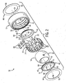
- the example bearing assembly (10) described below is in the form of a double-row, cylindrical roller bearing assembly.
- inventive concepts described herein can be incorporated with any other form of bearing assembly, such as the various bearing assemblies manufactured by Rexnord Industries, LLC of Milwaukee, Wisconsin.
- terms such as front, back, side, top, bottom, up, down, upper, lower, inner, outer, above, below, and the like are used to describe the relative arrangement and/or operation of various components of the example embodiment; none of these relative terms are to be construed as limiting the construction or alternative arrangements that are within the scope of the claims.
- the example bearing assembly (10) illustrated in FIG. 1 is configured to provide relative rotation between two objects (e.g., a fixed object and a rotating object).
- the example bearing assembly (10) includes a bearing member in the form of an outer ring (12) that may be fixed (e.g., captured in a pillow block) and another bearing member in the form of an inner ring (14) that may be secured to a rotating member (e.g., a shaft rotating relative to the pillow block).
- the inner ring (14) is oriented radially inward of the outer ring (12) in typical double-row, cylindrical roller bearing arrangement.
- the overall form factor of a bearing assembly is generally influenced by the specific application requirements in which the bearing assembly is designed to operate.
- an application may call for bearing members in the form of parallel plates that rotate about a common axis and engage ball bearings between the plates to provide relative rotation of the plates. Therefore, it is appreciated that the example bearing assembly (10) described is merely one embodiment of the broader bearing assembly concept.
- the example bearing assembly (10) includes various components that are generally positioned between the outer ring (12) and the inner ring (14) to facilitate relative rotation between the outer ring (12) and the inner ring (14) (i.e., example bearing members).
- the outer ring (12) defines an outer race (16)
- the inner ring (14) defines an inner race (18) in which pluralities of cylindrical rollers (20) are seated and roll against during operation of the bearing assembly (10).
- the cylindrical rollers (20) are held in relative arrangement by a separator or retainer ring (22) that is positioned between the outer ring (12) and the inner ring (14).
- the retainer ring (22) includes a central band (24) and multiple transverse fingers (26) that are circumferentially spaced apart, thereby defining gaps (28) between successive transverse fingers (26) in which the cylindrical rollers (20) are located.
- the central band (24) and transverse fingers (26) are tapered radially inward along respective taper surfaces (25, 27) such that the cylindrical rollers (20) are skewed relative to a longitudinal axis (A) of the bearing assembly (10) and are aligned to ride within the outer race (16) and the inner race (18).
- the outer race (16) and the inner race (18) define respective bearing surfaces against which the cylindrical rollers (20) engage to reduce relative friction between the outer ring (12) and the inner ring (14).
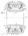
- the cylindrical rollers (20) have been removed from the cross section shown in FIG. 5 to better illustrate the contours of the example outer race (16) and the example inner race (18).
- the outer race (16) includes annular, arcuate bearing surfaces (30, 32) that are separated by an annular land surface (34). Beveled shoulders (36, 38) are formed along the outer perimeters of the bearing surfaces (30, 32).
- the inner race (18) of the example embodiment generally defines a spherical bearing surface (40) against which the cylindrical rollers (20) also engage during operation of the bearing assembly (10).
- the retainer ring (22) generally aligns each row of the cylindrical rollers (20) adjacent to the respective annular bearing surfaces (30, 32) and the spherical bearing surface (40).
- the skewed orientation of the cylindrical rollers (20) (relative to the longitudinal axis (A) of the bearing assembly (10)) provides resistance to axial loads and thrust loads imparted to the example bearing assembly (10).
- the outer ring (12) and the inner ring (14) may be made of AISI M62 steel or any other material having sufficient application-specific hardness for use in elevated temperature environments (e.g., upwards of approximately 815 degrees Celsius (1500 degrees Fahrenheit)). Given the benefit of this disclosure, one skilled in the art will appreciate the various bearing assembly configurations and orientations available depending on the specific application design.
- the example bearing assembly (10) includes floating seals (42, 44) and shields (46, 48) on each side of the bearing assembly (10) to inhibit contaminants from entering and fouling the operation of the bearing assembly (10).
- a single floating seal (42) and a single shield (46) will be described in detail with the understanding that the other floating seal (44) and shield (48) are generally similar.
- certain bearing assembly applications may only benefit from a single floating seal/shield arrangement, such as when a portion of the bearing assembly is housed within a sealed case.
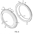
- the example shield (46) is generally ring-shaped having an inner face (50) spaced apart from and parallel to an outer face (52).
- the inner face (50) and the outer face (52) are connected by an inner peripheral surface (54) and an outer peripheral surface (56), thus establishing the general ring shape of the shield (46).
- the shield (46) can be made of a variety of materials, including for example stainless steel (e.g., 304/304L, 316/316L, 430, etc.), metal alloys (e.g., 4140, 4142, 4150, 4340, etc.), bimetals (e.g., Cobalt based spring alloys, such as NEOMAX KRN-1 and KRN-2 manufactured by Neomax Materials, Co., Ltd. based in Osaka, Japan), and any other materials suitable to withstand the specific application requirements (e.g., temperatures approaching or exceeding 815 degrees Celsius (1500 degrees Fahrenheit)).
- stainless steel e.g., 304/304L, 316/316L, 430, etc.
- metal alloys e.g., 4140, 4142, 4150, 4340, etc.
- bimetals e.g., Cobalt based spring alloys, such as NEOMAX KRN-1 and KRN-2 manufactured by Neomax Materials, Co., Ltd. based in Osaka
- a coating may be applied to the inner face (50) of the shield (46), which engages the floating seal (42) during use to reduce friction and accommodate high-temperature operation.
- the coating may include chrome plating, ceramic coating, application specific coatings (e.g., PT1 101 - Tribaloy T-800 manufactured by Deloro Stellite Group of Houston, Texas and PT1 285 - Tribaglide manufactured by Plasma Technology, Inc. of Torrance, California), or any other coating that is capable of reducing friction and withstanding the particular application requirements.
- An annular flange (66) protrudes radially outward from the balance of the floating seal (42) and is defined in part by the interior face (58).
- the annular flange (66) further defines a cylindrical peripheral face (68) that extends substantially perpendicular to the interior face (58).
- the cylindrical peripheral face (68) connects the interior face (58) to a ring-shaped shield face (70) of the annular flange (66), such that the shield face (70) is generally parallel to the interior face (58).
- the shield face (70) is engaged by the shield (46) when the floating seal (42) and the shield (46) are installed in the balance of the bearing assembly (10).
- the shield face (70) extends radially inward to a cylindrical radial face (72) that is parallel to the axis (A).
- a beveled face (74) angles radially inward toward the axis (A) to connect the radial face (72) to the exterior face (60).
- the floating seal (42) may be made of a variety of materials including, for instance, alloy steels (e.g., AISI M2, AISI M42, AISI BG42, AISI M50, etc.), stainless steel (e.g., 420, 440/440C, 17-4 PH, 17-5 PH, etc.), INCONEL manufactured by Special Metals Corporation of Huntington, West Virginia (e.g., UNS N06625, UNS N09706, UNS N0718, etc.), ceramics (e.g., silicon nitride, silicon carbide, zirconia oxide, etc.), and similar materials suitable for the particular application (e.g., applications in which temperatures are in the range of 1500 degrees Fahrenheit).
- alloy steels e.g., AISI M2, AISI M42, AISI BG42, AISI M50, etc.
- stainless steel e.g., 420, 440/440C, 17-4 PH, 17-5 PH, etc.
- the arcuate bearing face (62) and/or the shield face (70), for example, may include a coating, such as chrome plating, ceramic coating, application specific coatings (e.g., PT1 101 - Tribaloy T-800 manufactured by Deloro Stellite Group of Houston, Texas and PT1 285 - Tribaglide manufactured by Plasma Technology, Inc. of Torrance, California), or any other coating that is capable of reducing friction and withstanding the particular application requirements.
- a coating such as chrome plating, ceramic coating, application specific coatings (e.g., PT1 101 - Tribaloy T-800 manufactured by Deloro Stellite Group of Houston, Texas and PT1 285 - Tribaglide manufactured by Plasma Technology, Inc. of Torrance, California), or any other coating that is capable of reducing friction and withstanding the particular application requirements.
- the example floating seal (42) is installed to the balance of the bearing assembly (10) by engaging the arcuate bearing face (62) against the inner race (18) and then capturing the annular flange (66) of the floating seal (42) to the inner race (18) with the shield (46).
- the shield (46) is illustrated as being coupled to or engaged with the outer ring (12).
- the outer ring (12) defines an annular groove (76) into which the shield (46) is pressed into and axially restrained adjacent to the annular flange (66) of the floating seal (42).
- the shield (46) may be axially restrained by a lip or other restraint that allows the shield (46) to freely rotate about the axis (A).
- the shield (46) may be welded, adhered, or otherwise engaged with or coupled to the outer ring (12) to ultimately restrain movement of the floating seal (42) along and about the axis (A).
- the floating seal (42) is allowed to generally float, drift, and/or glide relative to the shield (46) and the inner race (18). As a result, the floating seal (42) may maintain sufficient sealing engagement when various components of the bearing assembly (10) are misaligned, for instance, as a result of thermodynamic or other forces acting on the bearing assembly (10) (e.g., loading the inner ring (14) normal to the axis (A)).
- the shield (46) is axially coupled with the outer ring (12) and captures the floating seal (42) adjacent to the inner ring (14) such that the floating seal (42) is slidably engaged with the shield (46) and the inner ring (14), which is the ring that is uncoupled from the shield (46).
- the arcuate bearing face (62) wipes against the inner race (18) such that contaminants are inhibited from passing between the floating seal (42) and the inner race (18). Moreover, engagement between the inner face (50) of the shield (46) and the shield face (70) of the floating seal (42) further inhibits contaminants from fouling the operation of the bearing assembly (10).
- the example construction may be adapted such that a shield is coupled to or engaged with an inner ring and a floating seal is captured by the shield adjacent to the outer ring, thereby providing desired sealing with a structure that is generally the inverse of that illustrated in the example bearing assembly (10).
- the floating seal arrangement defines the seal as being engaged with the bearing member that is not supporting the shield; in the example bearing assembly (10), the shield (46) is supported by the outer ring (12) to capture the floating seal (42) against the inner ring (14).
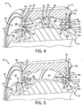
- FIGS. 7A and 7B having contoured profiles that are configured to bias the floating seal (42) toward the inner race (18).
- the first alternative shield (46A) includes a ridge (78) near an inner periphery (80) that is contoured to provide additional force to bias the floating seal (42) into engagement with the inner race (18) of the example bearing assembly (10).
- the second alternative shield (46B) includes a hump (82) substantially intermediate of an outer periphery (84) and an inner periphery (86). The hump (82) is also contoured to provide additional force to bias the floating seal (42) into engagement with the inner race (18) of the example bearing assembly (10).
Landscapes
- Engineering & Computer Science (AREA)
- General Engineering & Computer Science (AREA)
- Mechanical Engineering (AREA)
- Rolling Contact Bearings (AREA)
- Sealing Of Bearings (AREA)
- Support Of The Bearing (AREA)
Claims (10)
- Lageranordnung, umfassend:ein erstes Lagerteil (12);ein zweites Lagerteil (14), angeordnet neben dem ersten Lagerelement (12);mehrere Lagerelemente (20), positioniert zwischen dem ersten Lagerteil (12) und dem zweiten Lagerteil (14);eine Abschirmung (46; 48), verbunden mit dem ersten Lagerelement (12); undeine schwimmende Dichtung (42; 44), verschiebbar verbunden mit der Abschirmung (46; 48) und dem zweiten Lagerteil (14) während des Betriebs der Lageranordnung, wobei die schwimmende Dichtung (42; 44) eine gebogene Lagerfläche (62) definiert, verbunden mit einer im Wesentlichen gebogenen Lagerfläche (18) des zweiten Lagerteils (14); wobei die Abschirmung (46; 48) im Wesentlichen ringförmig ist, mit einer Innenfläche (50) in einem Abstand von und parallel zu einer Außenfläche (52), wobei die Innenfläche (50) und die Außenfläche (52) durch eine Innenumfangsoberfläche (54) und einer Außenumfangsoberfläche (56) verbunden sind und die Abschirmung (46; 48) die schwimmende Dichtung (42; 44) neben der Abschirmung (46; 48) und dem zweiten Lagerteil (14) zurückhält, um es der schwimmende Dichtung (42; 44) zu ermöglichen, in Bezug auf die Abschirmung (46; 48) und das zweite Lagerteil (14) während der Drehung von mindestens einem des ersten Lagerelements (12) und des zweiten Lagerelements (14) zu schwimmen, zu treiben und/oder zu gleiten;dadurch gekennzeichnet, dass:die schwimmende Dichtung (42; 44) aus mindestens einem Material aus der Gruppe von legiertem Stahl, rostfreiem Stahl, INCONEL und Keramik hergestellt ist,wobei die schwimmende Dichtung (42; 44) eine radiale Fläche (72) definiert, die radial auswärts von der gebogenen Lagerfläche (62) positioniert ist, und wobei ein Flansch (66) radial auswärts von der radialen Fläche (72) verläuft, definierend eine axiale Abschirmfläche (70), die mit der Abschirmung (46; 48) verbunden ist, um die schwimmende Dichtung (42; 44) zurückzuhalten, und wobei die gebogene Lagerfläche (62), die mit der im Wesentlichen gebogenen Lagerfläche (18), des zweiten Lagerteils (14) verbunden ist, in Richtung einer Längsachse axial über die Abschirmung (46; 48) hinaus verläuft.
- Lageranordnung nach Anspruch 1, wobei:das erste Lagerteil (12) ein Außenring (12) ist; und das zweite Lagerteil (14) ein Innenring (14) ist, der radial einwärts von dem Außenring (12) angeordnet ist.
- Lageranordnung nach Anspruch 1, wobei die schwimmende Dichtung 42; 44) aus mindestens einem von einem legiertem Stahl und einem rostfreien Stahl hergestellt ist.
- Lageranordnung nach Anspruch 1, wobei die gebogene Lagerfläche (62) der schwimmenden Dichtung (42; 44) mit mindestens einem von einer Verchromung und einer Keramikbeschichtung beschichtet ist.
- Lageranordnung nach Anspruch 1, wobei:eine Rille (76) in dem ersten Lagerteil (12) geformt ist; und die Abschirmung (46; 48) in der Rille (76) erfasst ist.
- Lageranordnung nach Anspruch 1, wobei:das erste Lagerteil (12) sich in Bezug auf das zweite Lagerteil (14) um die Längsachse dreht; und die Abschirmfläche (70) im Wesentlichen plan und im Wesentlichen senkrecht zu der Längsachse ausgerichtet ist.
- Lageranordnung nach Anspruch 1, wobei die Abschirmung (46; 48) ein Konturprofil definiert, konfiguriert, um die schwimmende Dichtung (42; 44) zu dem zweiten Lagerteil (14) hin zu neigen.
- Lageranordnung nach Anspruch 2, wobei:der Außenring (12) eine Außenlaufbahn (16) hat;der Innenring (14) eine Innenlaufbahn (16) hat, die mehreren der Lagerelemente (20) zwischen dem Außenring (12) und dem Innenring (14) positioniert sind und in der Innenlaufbahn (16) und der Außenlaufbahn (16) sitzen;die an den Außenring (12) gekoppelte Abschirmung (46; 48) eine axiale Innenfläche (50) und eine axiale Außenfläche (52) definiert;wobei die gebogene Lagerfläche (62), die mit dem Innenring (14) verbunden ist, längs über die axiale Innenfläche (50) und die axiale Außenfläche (52) der Abschirmung (46; 48) hinaus verläuft;wobei die Abschirmung (46; 48) die schwimmende Dichtung (42; 44) neben der Abschirmung (46; 48) und dem Innenring (14) so zurückhält, dass die schwimmende Dichtung (42; 44) in Bezug auf die Abschirmung (46; 48) und den Innenring (14) während der relativen Drehung zwischen dem Außenring (12) und dem Innenring (14) schwimmen, treiben und/oder gleiten kann.
- Lageranordnung nach Anspruch 1, wobei der Flansch (66) ein ringförmiger Flansch ist.
- Lageranordnung nach Anspruch 2, wobei die Abschirmung (46; 48) in einer Rille (76), gebildet in dem Außenring (12) durch eine Pressfassung und eine Lippe, gebildet auf dem Außenring (12), erfasst ist.
Applications Claiming Priority (1)
| Application Number | Priority Date | Filing Date | Title |
|---|---|---|---|
| US13/287,789 US8740464B2 (en) | 2011-11-02 | 2011-11-02 | Bearing assembly having a floating seal |
Publications (2)
| Publication Number | Publication Date |
|---|---|
| EP2589829A1 EP2589829A1 (de) | 2013-05-08 |
| EP2589829B1 true EP2589829B1 (de) | 2015-05-27 |
Family
ID=47172365
Family Applications (1)
| Application Number | Title | Priority Date | Filing Date |
|---|---|---|---|
| EP12189693.0A Not-in-force EP2589829B1 (de) | 2011-11-02 | 2012-10-24 | Lageranordnung mit Schwimmdichtung |
Country Status (4)
| Country | Link |
|---|---|
| US (1) | US8740464B2 (de) |
| EP (1) | EP2589829B1 (de) |
| JP (1) | JP5592922B2 (de) |
| CN (1) | CN103089808A (de) |
Families Citing this family (25)
| Publication number | Priority date | Publication date | Assignee | Title |
|---|---|---|---|---|
| US10012265B2 (en) | 2007-12-06 | 2018-07-03 | Roller Bearing Company Of America, Inc. | Corrosion resistant bearing material |
| US9561845B2 (en) | 2007-12-06 | 2017-02-07 | Roller Bearing Company Of America, Inc. | Bearing installed on an aircraft structure |
| CN103003600B (zh) * | 2010-04-06 | 2015-09-02 | Skf公司 | 具有密封环的轴向推力轴承装置 |
| US9227720B2 (en) | 2013-03-01 | 2016-01-05 | Roller Bearing Company Of America, Inc. | Composite annular seal assembly for bearings in aircraft |
| USD713715S1 (en) | 2013-08-08 | 2014-09-23 | Neoperl Gmbh | Coupling nut |
| US10077808B2 (en) | 2013-12-18 | 2018-09-18 | Roller Bearing Company Of America, Inc. | Roller profile for hourglass roller bearings in aircraft |
| US9394939B2 (en) | 2014-01-31 | 2016-07-19 | CEROBEAR GmbH | Bearing system and methods of use thereof |
| GB2527490A (en) * | 2014-04-17 | 2015-12-30 | Ip Dept Airbus Operations Ltd | A bearing block for a slat support assembly |
| CN104283344A (zh) * | 2014-05-28 | 2015-01-14 | 莱克电气股份有限公司 | 一种转子及其加工装配方法 |
| EP2952758B1 (de) * | 2014-06-03 | 2019-03-06 | Roller Bearing Company of America, Inc. | Korrosionsbeständiger lager |
| US9890814B2 (en) * | 2014-06-03 | 2018-02-13 | Roller Bearing Company Of America, Inc. | Cage for hourglass roller bearings |
| EP2957781B1 (de) * | 2014-06-03 | 2019-09-25 | Roller Bearing Company of America, Inc. | Trageinrichtung einer klappe an der hinterkante eines flugzeugflügels mit einem zweireihigen pendelrollenlager mit konkaven rollen |
| USD757524S1 (en) * | 2014-06-13 | 2016-05-31 | Aerus Llc | Drive pulley |
| USD757525S1 (en) * | 2014-07-25 | 2016-05-31 | GoldieBlox, Inc. | Pulley |
| CN107002761B (zh) * | 2014-09-17 | 2019-02-15 | 舍弗勒技术股份两合公司 | 可变转矩轴承 |
| USD742214S1 (en) * | 2014-11-21 | 2015-11-03 | Group-A Autosports, Inc. | Pulley shaft |
| US10082179B2 (en) | 2014-12-16 | 2018-09-25 | Roller Bearing Company Of America, Inc. | Seal for self aligning roller bearing |
| JP6282609B2 (ja) * | 2015-03-31 | 2018-02-21 | ミネベアミツミ株式会社 | 転がり軸受 |
| US9909453B2 (en) | 2015-05-19 | 2018-03-06 | General Electric Company | Lubrication system for a turbine engine |
| US10415429B2 (en) | 2015-09-25 | 2019-09-17 | General Electric Company | Planet gearbox with cylindrical roller bearing with high density roller packing |
| US10234018B2 (en) | 2015-10-19 | 2019-03-19 | General Electric Company | Planet gearbox with cylindrical roller bearing with under race lube scheme |
| DE102015220962B4 (de) * | 2015-10-27 | 2022-06-30 | Aktiebolaget Skf | Lageranordnung mit Vorspannung |
| ITUB20156062A1 (it) | 2015-12-01 | 2017-06-01 | Gen Electric | Alloggiamento per l'uso in un motore a turboventilatore e procedimento di lavaggio di fluido da esso. |
| CA2977081A1 (en) * | 2016-08-22 | 2018-02-22 | Terex Usa, Llc | Material processing screen plant drive system |
| CN111195583B (zh) * | 2018-11-20 | 2023-02-28 | 群翊工业股份有限公司 | 具有气浮轴承的烘箱及其应用方法 |
Family Cites Families (73)
| Publication number | Priority date | Publication date | Assignee | Title |
|---|---|---|---|---|
| US1469991A (en) | 1923-10-09 | Means for preventing displacement of rollers-in | ||
| US662374A (en) | 1900-04-24 | 1900-11-20 | Thomas B Dooley | Antifriction-bearing. |
| US1528363A (en) | 1921-10-01 | 1925-03-03 | Wilhelm B Bronander | Roller bearing |
| US1646947A (en) | 1923-10-08 | 1927-10-25 | Percy A E Armstrong | Means for preventing displacement in rollers for roller bearings |
| US1781886A (en) | 1929-03-15 | 1930-11-18 | Timken Roller Bearing Co | Self-aligning roller bearing |
| US1910184A (en) | 1930-06-07 | 1933-05-23 | Timken Roller Bearing Co | Self-aligning roller bearing |
| US1973994A (en) | 1932-12-21 | 1934-09-18 | Shafer Bearing Corp | Antifriction bearing |
| US2298463A (en) | 1940-01-06 | 1942-10-13 | Fafnir Bearing Co | Bearing seal |
| US2486123A (en) | 1944-07-15 | 1949-10-25 | American Steel Foundries | Journal connection |
| US2592082A (en) | 1948-11-06 | 1952-04-08 | Clark Bros Co Inc | Floating shaft seal |
| US2653064A (en) | 1951-12-28 | 1953-09-22 | Heim Company | Ball bearing |
| US2767037A (en) * | 1954-02-09 | 1956-10-16 | Chain Belt Co | Seal for rotary anti-friction bearings |
| DE1020499B (de) | 1955-01-19 | 1957-12-05 | Heinrich Lanz Ag | Dichtung fuer Pendellager, insbesondere Pendelkugellager |
| US3141708A (en) | 1961-08-28 | 1964-07-21 | Gen Motors Corp | Demountable closure |
| US3655251A (en) | 1970-07-15 | 1972-04-11 | Christopher B Evenson | Elliptical roller bearing |
| US3768881A (en) | 1972-10-02 | 1973-10-30 | Bendix Corp | Wheel bearing seal |
| AT336059B (de) | 1974-01-10 | 1977-04-12 | Voest Ag | Lager zur aufnahme von winkelauslenkungen an drehmoment ubertragenden zapfen |
| US3866985A (en) | 1974-03-04 | 1975-02-18 | Caterpillar Tractor Co | Track roller |
| US4557613A (en) | 1978-09-01 | 1985-12-10 | Skf Industries, Inc. | Spherical roller bearing having reciprocal crowning for skew control |
| JPS609460Y2 (ja) * | 1979-09-03 | 1985-04-03 | 日本精工株式会社 | 強制潤滑機能を備えたシ−ル体を有するころ軸受装置 |
| DE7935867U1 (de) | 1979-12-20 | 1980-03-27 | Fag Kugelfischer Georg Schaefer & Co, 8720 Schweinfurt | Abgedichtetes Wälzlager |
| GB2071224B (en) * | 1980-03-04 | 1983-09-21 | Nippon Seiko Kk | Sealing device for a roller bearing having an outer race with rib |
| FR2477652A1 (fr) | 1980-03-10 | 1981-09-11 | Nippon Seiko Kk | Dispositif d'etancheite pour palier a rouleaux |
| SE437412B (sv) | 1984-04-24 | 1985-02-25 | Skf Nova Ab | Anordning for tetning av ett sjelvinstellande rullningslager |
| SE449908B (sv) | 1984-09-26 | 1987-05-25 | Skf Ab | Rullager der rullarna och lopbanorna har krokta lengdsnittsprofiler |
| US4674993A (en) | 1985-02-28 | 1987-06-23 | The Zeller Corporation | Tripot universal joint of the end motion type |
| US4819949A (en) | 1985-12-19 | 1989-04-11 | Timken Company | Shielded seal assembly |
| SE451081B (sv) | 1986-03-25 | 1987-08-31 | Skf Nova Ab | Tetning for sjelvinstellande sferiska rullningslager |
| US4808012A (en) | 1987-03-23 | 1989-02-28 | The Timken Company | Flap seal for anti-friction bearings |
| US4763905A (en) | 1987-12-04 | 1988-08-16 | Allied-Signal Inc. | Seal retention and anti-rotation locking assembly |
| GB2219359B (en) | 1988-05-30 | 1992-11-04 | Ntn Toyo Bearing Co Ltd | Roller elements for machine parts such as roller bearings. |
| US4960334A (en) | 1989-03-02 | 1990-10-02 | The Zeller Corporation | Support for rotatably supporting a shaft |
| DE8904504U1 (de) | 1989-04-11 | 1989-05-18 | Fag Kugelfischer Georg Schaefer Kgaa, 8720 Schweinfurt, De | |
| US4872770A (en) | 1989-04-20 | 1989-10-10 | The Torrington Company | Antifriction bearing with seal arrangement |
| DE3926493A1 (de) | 1989-08-10 | 1991-02-14 | Krupp Polysius Ag | Lagerkonstruktion einer maschine |
| GB8922563D0 (en) | 1989-10-06 | 1989-11-22 | Rhp Bearings Ltd | Improvements in roller bearings |
| US5002406A (en) | 1990-02-20 | 1991-03-26 | Emerson Electric Co. | Sealing structure for a spherical bearing assembly |
| US5000587A (en) | 1990-03-02 | 1991-03-19 | Link-Belt Bearings Division Of Rexnord Corporation | Bearing assembly and auxiliary bearing seal |
| SE464258B (sv) | 1990-04-18 | 1991-03-25 | Skf Ab | Taetat sfaeriskt rullningslager |
| DE9005328U1 (de) | 1990-05-10 | 1990-07-12 | Ina Waelzlager Schaeffler Kg, 8522 Herzogenaurach, De | |
| SE9101962L (sv) | 1991-06-26 | 1992-12-27 | Skf Ab | Taetat lager |
| IT1255023B (it) * | 1992-03-27 | 1995-10-13 | Supporto perfezionato per cuscinetti evolventi | |
| US5352047A (en) | 1992-07-13 | 1994-10-04 | Rexnord Corporation | Snap-tab roller bearing case |
| US5340124A (en) | 1992-08-14 | 1994-08-23 | Allied-Signal Inc. | Seal retention and anti-rotation locking assembly |
| JPH06200949A (ja) | 1992-11-10 | 1994-07-19 | Toyo Seal Kogyo Kk | 軸受用密封板の装着方法および軸受用密封装置 |
| US5242229A (en) | 1992-11-25 | 1993-09-07 | The Torrington Company | Sealing structure for standardized bearing ring |
| US5441351A (en) | 1993-10-26 | 1995-08-15 | Rexnord Corporation | Full complement self-aligning roller bearing |
| US5413416A (en) * | 1993-12-03 | 1995-05-09 | Rexnord Corporation | Roller guide member for full complement roller bearing |
| US5695290A (en) | 1995-06-20 | 1997-12-09 | The Torrington Company | Antifriction bearing with seal arrangement |
| SE509420C2 (sv) * | 1995-11-09 | 1999-01-25 | Skf Ab | Avtätat lager |
| US5839834A (en) | 1996-09-30 | 1998-11-24 | The Torrington Company | Bearing and bearing seal |
| AU7848998A (en) | 1996-12-10 | 1998-07-03 | Timken Company, The | Spring-biased seal |
| DE19809171A1 (de) | 1998-03-04 | 1999-09-09 | Schaeffler Waelzlager Ohg | Nadellager |
| US6315458B1 (en) | 1998-06-19 | 2001-11-13 | Nsk Ltd. | Roller bearing |
| JP2000198304A (ja) * | 1998-10-29 | 2000-07-18 | Nsk Ltd | 車輪用転がり軸受ユニット |
| JP4014021B2 (ja) | 1998-12-10 | 2007-11-28 | 株式会社ショーワ | プロペラシャフト支持構造 |
| JP2003501595A (ja) | 1999-06-04 | 2003-01-14 | グラコ・インコーポレーテッド | 湿式カップ、スロートシール及びベアリングアセンブリ |
| US6354745B1 (en) | 1999-09-16 | 2002-03-12 | The Timken Company | Fully self-aligning roller bearing |
| DE10037150A1 (de) | 2000-07-31 | 2002-02-21 | Hilti Ag | Lagerdichtung |
| US6394656B1 (en) | 2000-09-05 | 2002-05-28 | Rexnord Corporation | Retainerless precessing roller bearing |
| US6406187B1 (en) | 2000-10-09 | 2002-06-18 | Meritor Heavy Vehicle Technology, Llc | Grease lock seal |
| US6626575B2 (en) | 2001-06-07 | 2003-09-30 | Roller Bearing Company Of America | Spherical plain bearing with spread lock dual sealing means |
| AU2003221012A1 (en) | 2002-03-25 | 2003-10-08 | Nsk Ltd. | Seal ring, and roller bearing unit with seal ring |
| US20050058382A1 (en) * | 2003-09-15 | 2005-03-17 | Williams Steven S. | Steering hub bearing assembly |
| US7097363B2 (en) | 2003-12-08 | 2006-08-29 | Arvinmeritor Technology, Llc | Center bearing seal assembly |
| JP2006300129A (ja) | 2005-04-18 | 2006-11-02 | Ntn Corp | 球面滑り軸受 |
| DE102005029936B4 (de) | 2005-06-28 | 2016-01-07 | Schaeffler Technologies AG & Co. KG | Abgedichtetes Wälzlager |
| US7637665B2 (en) | 2006-06-30 | 2009-12-29 | Emerson Power Transmission Corporation | Bearing assembly and resilient seal element |
| US7422373B2 (en) | 2006-08-22 | 2008-09-09 | Emerson Power Transmission Manufacturing | Spherical roller bearing sealing assembly |
| CN201087178Y (zh) * | 2007-09-04 | 2008-07-16 | 林敏� | 真空离子镀铬陶瓷器 |
| BRPI0814792B1 (pt) | 2008-04-21 | 2019-04-02 | Circor Reliability Services Company | Unidade e sistema de mancal e vedação de autoalinhamento |
| CN201232594Y (zh) * | 2008-07-25 | 2009-05-06 | 福建东亚机械有限公司 | 一种氮化后外圆复合电镀铬层和陶瓷微粒的活塞环 |
| US8061903B2 (en) * | 2010-01-28 | 2011-11-22 | Rexnord Industries, Llc | Bearing assembly with extended maintenance interval |
-
2011
- 2011-11-02 US US13/287,789 patent/US8740464B2/en active Active
-
2012
- 2012-10-09 JP JP2012223870A patent/JP5592922B2/ja active Active
- 2012-10-24 EP EP12189693.0A patent/EP2589829B1/de not_active Not-in-force
- 2012-10-31 CN CN2012104293271A patent/CN103089808A/zh active Pending
Also Published As
| Publication number | Publication date |
|---|---|
| CN103089808A (zh) | 2013-05-08 |
| US8740464B2 (en) | 2014-06-03 |
| EP2589829A1 (de) | 2013-05-08 |
| JP5592922B2 (ja) | 2014-09-17 |
| JP2013096575A (ja) | 2013-05-20 |
| US20130108200A1 (en) | 2013-05-02 |
Similar Documents
| Publication | Publication Date | Title |
|---|---|---|
| EP2589829B1 (de) | Lageranordnung mit Schwimmdichtung | |
| US9169874B2 (en) | Peripheral sealing arrangement | |
| US6325380B1 (en) | Face seal assembly | |
| EP2224103B1 (de) | Lagergehäuse mit Quetschölfilmdämpfer | |
| EP2246581B1 (de) | Rollenlager mit Dichtungsanordnung | |
| US8535009B2 (en) | Tapered roller bearing | |
| EP2829777B1 (de) | Kugelventildichtung mit dynamischer C-Dichtung und statischer C-Dichtung | |
| EP2484925B1 (de) | Ventilanordnung mit einem Kombinationslager mit verbesserter Tragfähigkeit und Lebensdauer | |
| US20110182539A1 (en) | Bearing Assembly with Extended Maintenance Interval | |
| US9561845B2 (en) | Bearing installed on an aircraft structure | |
| US9989090B2 (en) | Slewing roller bearing with sealing arrangement | |
| US9151391B2 (en) | Labyrinth seal having labyrinth rings with different wear resistances | |
| US9394939B2 (en) | Bearing system and methods of use thereof | |
| JP2008256204A (ja) | 転がり軸受 | |
| EP2957781B1 (de) | Trageinrichtung einer klappe an der hinterkante eines flugzeugflügels mit einem zweireihigen pendelrollenlager mit konkaven rollen | |
| US10385921B2 (en) | Combination bearing and seal assembly for rotatable shafts | |
| CN202165448U (zh) | 一种耐高温轴承密封装置 | |
| EP3048344B1 (de) | Dichtungsgehäuse-vorverjüngung | |
| JP2015086955A (ja) | 転がり軸受用の分割保持器 | |
| US20130075976A1 (en) | Compliant mounting of an axial face seal assembly | |
| EP3336370B1 (de) | Nockenfolger- und kreuzgelenkgabelanordnungen | |
| US8858087B2 (en) | Bearing assembly | |
| EP3557089B1 (de) | Lagerzentrierfeder und dämpfer | |
| KR101349802B1 (ko) | 볼 베어링 | |
| US20220196072A1 (en) | Rolling bearing with removable sealing module |
Legal Events
| Date | Code | Title | Description |
|---|---|---|---|
| PUAI | Public reference made under article 153(3) epc to a published international application that has entered the european phase |
Free format text: ORIGINAL CODE: 0009012 |
|
| AK | Designated contracting states |
Kind code of ref document: A1 Designated state(s): AL AT BE BG CH CY CZ DE DK EE ES FI FR GB GR HR HU IE IS IT LI LT LU LV MC MK MT NL NO PL PT RO RS SE SI SK SM TR |
|
| AX | Request for extension of the european patent |
Extension state: BA ME |
|
| 17P | Request for examination filed |
Effective date: 20130802 |
|
| RBV | Designated contracting states (corrected) |
Designated state(s): AL AT BE BG CH CY CZ DE DK EE ES FI FR GB GR HR HU IE IS IT LI LT LU LV MC MK MT NL NO PL PT RO RS SE SI SK SM TR |
|
| RIC1 | Information provided on ipc code assigned before grant |
Ipc: F16C 33/78 20060101AFI20130930BHEP Ipc: F16C 23/08 20060101ALI20130930BHEP |
|
| 17Q | First examination report despatched |
Effective date: 20140416 |
|
| GRAP | Despatch of communication of intention to grant a patent |
Free format text: ORIGINAL CODE: EPIDOSNIGR1 |
|
| INTG | Intention to grant announced |
Effective date: 20141215 |
|
| GRAS | Grant fee paid |
Free format text: ORIGINAL CODE: EPIDOSNIGR3 |
|
| GRAA | (expected) grant |
Free format text: ORIGINAL CODE: 0009210 |
|
| AK | Designated contracting states |
Kind code of ref document: B1 Designated state(s): AL AT BE BG CH CY CZ DE DK EE ES FI FR GB GR HR HU IE IS IT LI LT LU LV MC MK MT NL NO PL PT RO RS SE SI SK SM TR |
|
| REG | Reference to a national code |
Ref country code: GB Ref legal event code: FG4D |
|
| REG | Reference to a national code |
Ref country code: CH Ref legal event code: EP |
|
| REG | Reference to a national code |
Ref country code: AT Ref legal event code: REF Ref document number: 729028 Country of ref document: AT Kind code of ref document: T Effective date: 20150615 |
|
| REG | Reference to a national code |
Ref country code: IE Ref legal event code: FG4D |
|
| REG | Reference to a national code |
Ref country code: DE Ref legal event code: R096 Ref document number: 602012007543 Country of ref document: DE |
|
| REG | Reference to a national code |
Ref country code: AT Ref legal event code: MK05 Ref document number: 729028 Country of ref document: AT Kind code of ref document: T Effective date: 20150527 |
|
| REG | Reference to a national code |
Ref country code: LT Ref legal event code: MG4D |
|
| PG25 | Lapsed in a contracting state [announced via postgrant information from national office to epo] |
Ref country code: PT Free format text: LAPSE BECAUSE OF FAILURE TO SUBMIT A TRANSLATION OF THE DESCRIPTION OR TO PAY THE FEE WITHIN THE PRESCRIBED TIME-LIMIT Effective date: 20150928 Ref country code: NO Free format text: LAPSE BECAUSE OF FAILURE TO SUBMIT A TRANSLATION OF THE DESCRIPTION OR TO PAY THE FEE WITHIN THE PRESCRIBED TIME-LIMIT Effective date: 20150827 Ref country code: ES Free format text: LAPSE BECAUSE OF FAILURE TO SUBMIT A TRANSLATION OF THE DESCRIPTION OR TO PAY THE FEE WITHIN THE PRESCRIBED TIME-LIMIT Effective date: 20150527 Ref country code: LT Free format text: LAPSE BECAUSE OF FAILURE TO SUBMIT A TRANSLATION OF THE DESCRIPTION OR TO PAY THE FEE WITHIN THE PRESCRIBED TIME-LIMIT Effective date: 20150527 Ref country code: FI Free format text: LAPSE BECAUSE OF FAILURE TO SUBMIT A TRANSLATION OF THE DESCRIPTION OR TO PAY THE FEE WITHIN THE PRESCRIBED TIME-LIMIT Effective date: 20150527 Ref country code: HR Free format text: LAPSE BECAUSE OF FAILURE TO SUBMIT A TRANSLATION OF THE DESCRIPTION OR TO PAY THE FEE WITHIN THE PRESCRIBED TIME-LIMIT Effective date: 20150527 |
|
| REG | Reference to a national code |
Ref country code: NL Ref legal event code: MP Effective date: 20150527 |
|
| PG25 | Lapsed in a contracting state [announced via postgrant information from national office to epo] |
Ref country code: IS Free format text: LAPSE BECAUSE OF FAILURE TO SUBMIT A TRANSLATION OF THE DESCRIPTION OR TO PAY THE FEE WITHIN THE PRESCRIBED TIME-LIMIT Effective date: 20150927 Ref country code: RS Free format text: LAPSE BECAUSE OF FAILURE TO SUBMIT A TRANSLATION OF THE DESCRIPTION OR TO PAY THE FEE WITHIN THE PRESCRIBED TIME-LIMIT Effective date: 20150527 Ref country code: GR Free format text: LAPSE BECAUSE OF FAILURE TO SUBMIT A TRANSLATION OF THE DESCRIPTION OR TO PAY THE FEE WITHIN THE PRESCRIBED TIME-LIMIT Effective date: 20150828 Ref country code: BG Free format text: LAPSE BECAUSE OF FAILURE TO SUBMIT A TRANSLATION OF THE DESCRIPTION OR TO PAY THE FEE WITHIN THE PRESCRIBED TIME-LIMIT Effective date: 20150827 Ref country code: LV Free format text: LAPSE BECAUSE OF FAILURE TO SUBMIT A TRANSLATION OF THE DESCRIPTION OR TO PAY THE FEE WITHIN THE PRESCRIBED TIME-LIMIT Effective date: 20150527 Ref country code: AT Free format text: LAPSE BECAUSE OF FAILURE TO SUBMIT A TRANSLATION OF THE DESCRIPTION OR TO PAY THE FEE WITHIN THE PRESCRIBED TIME-LIMIT Effective date: 20150527 |
|
| PG25 | Lapsed in a contracting state [announced via postgrant information from national office to epo] |
Ref country code: DK Free format text: LAPSE BECAUSE OF FAILURE TO SUBMIT A TRANSLATION OF THE DESCRIPTION OR TO PAY THE FEE WITHIN THE PRESCRIBED TIME-LIMIT Effective date: 20150527 Ref country code: EE Free format text: LAPSE BECAUSE OF FAILURE TO SUBMIT A TRANSLATION OF THE DESCRIPTION OR TO PAY THE FEE WITHIN THE PRESCRIBED TIME-LIMIT Effective date: 20150527 |
|
| PG25 | Lapsed in a contracting state [announced via postgrant information from national office to epo] |
Ref country code: PL Free format text: LAPSE BECAUSE OF FAILURE TO SUBMIT A TRANSLATION OF THE DESCRIPTION OR TO PAY THE FEE WITHIN THE PRESCRIBED TIME-LIMIT Effective date: 20150527 Ref country code: RO Free format text: LAPSE BECAUSE OF NON-PAYMENT OF DUE FEES Effective date: 20150527 Ref country code: SK Free format text: LAPSE BECAUSE OF FAILURE TO SUBMIT A TRANSLATION OF THE DESCRIPTION OR TO PAY THE FEE WITHIN THE PRESCRIBED TIME-LIMIT Effective date: 20150527 Ref country code: CZ Free format text: LAPSE BECAUSE OF FAILURE TO SUBMIT A TRANSLATION OF THE DESCRIPTION OR TO PAY THE FEE WITHIN THE PRESCRIBED TIME-LIMIT Effective date: 20150527 |
|
| REG | Reference to a national code |
Ref country code: DE Ref legal event code: R097 Ref document number: 602012007543 Country of ref document: DE |
|
| PLBE | No opposition filed within time limit |
Free format text: ORIGINAL CODE: 0009261 |
|
| STAA | Information on the status of an ep patent application or granted ep patent |
Free format text: STATUS: NO OPPOSITION FILED WITHIN TIME LIMIT |
|
| PG25 | Lapsed in a contracting state [announced via postgrant information from national office to epo] |
Ref country code: IT Free format text: LAPSE BECAUSE OF FAILURE TO SUBMIT A TRANSLATION OF THE DESCRIPTION OR TO PAY THE FEE WITHIN THE PRESCRIBED TIME-LIMIT Effective date: 20150527 |
|
| REG | Reference to a national code |
Ref country code: DE Ref legal event code: R119 Ref document number: 602012007543 Country of ref document: DE |
|
| 26N | No opposition filed |
Effective date: 20160301 |
|
| PG25 | Lapsed in a contracting state [announced via postgrant information from national office to epo] |
Ref country code: SI Free format text: LAPSE BECAUSE OF FAILURE TO SUBMIT A TRANSLATION OF THE DESCRIPTION OR TO PAY THE FEE WITHIN THE PRESCRIBED TIME-LIMIT Effective date: 20150527 Ref country code: LU Free format text: LAPSE BECAUSE OF FAILURE TO SUBMIT A TRANSLATION OF THE DESCRIPTION OR TO PAY THE FEE WITHIN THE PRESCRIBED TIME-LIMIT Effective date: 20151024 |
|
| REG | Reference to a national code |
Ref country code: CH Ref legal event code: PL |
|
| PG25 | Lapsed in a contracting state [announced via postgrant information from national office to epo] |
Ref country code: MC Free format text: LAPSE BECAUSE OF FAILURE TO SUBMIT A TRANSLATION OF THE DESCRIPTION OR TO PAY THE FEE WITHIN THE PRESCRIBED TIME-LIMIT Effective date: 20150527 |
|
| REG | Reference to a national code |
Ref country code: IE Ref legal event code: MM4A |
|
| PG25 | Lapsed in a contracting state [announced via postgrant information from national office to epo] |
Ref country code: DE Free format text: LAPSE BECAUSE OF NON-PAYMENT OF DUE FEES Effective date: 20160503 Ref country code: LI Free format text: LAPSE BECAUSE OF NON-PAYMENT OF DUE FEES Effective date: 20151031 Ref country code: CH Free format text: LAPSE BECAUSE OF NON-PAYMENT OF DUE FEES Effective date: 20151031 |
|
| REG | Reference to a national code |
Ref country code: FR Ref legal event code: ST Effective date: 20160630 |
|
| PG25 | Lapsed in a contracting state [announced via postgrant information from national office to epo] |
Ref country code: BE Free format text: LAPSE BECAUSE OF FAILURE TO SUBMIT A TRANSLATION OF THE DESCRIPTION OR TO PAY THE FEE WITHIN THE PRESCRIBED TIME-LIMIT Effective date: 20150527 Ref country code: FR Free format text: LAPSE BECAUSE OF NON-PAYMENT OF DUE FEES Effective date: 20151102 |
|
| PG25 | Lapsed in a contracting state [announced via postgrant information from national office to epo] |
Ref country code: IE Free format text: LAPSE BECAUSE OF NON-PAYMENT OF DUE FEES Effective date: 20151024 |
|
| PG25 | Lapsed in a contracting state [announced via postgrant information from national office to epo] |
Ref country code: SM Free format text: LAPSE BECAUSE OF FAILURE TO SUBMIT A TRANSLATION OF THE DESCRIPTION OR TO PAY THE FEE WITHIN THE PRESCRIBED TIME-LIMIT Effective date: 20150527 Ref country code: HU Free format text: LAPSE BECAUSE OF FAILURE TO SUBMIT A TRANSLATION OF THE DESCRIPTION OR TO PAY THE FEE WITHIN THE PRESCRIBED TIME-LIMIT; INVALID AB INITIO Effective date: 20121024 |
|
| GBPC | Gb: european patent ceased through non-payment of renewal fee |
Effective date: 20161024 |
|
| PG25 | Lapsed in a contracting state [announced via postgrant information from national office to epo] |
Ref country code: NL Free format text: LAPSE BECAUSE OF FAILURE TO SUBMIT A TRANSLATION OF THE DESCRIPTION OR TO PAY THE FEE WITHIN THE PRESCRIBED TIME-LIMIT Effective date: 20150527 Ref country code: SE Free format text: LAPSE BECAUSE OF FAILURE TO SUBMIT A TRANSLATION OF THE DESCRIPTION OR TO PAY THE FEE WITHIN THE PRESCRIBED TIME-LIMIT Effective date: 20150527 Ref country code: CY Free format text: LAPSE BECAUSE OF FAILURE TO SUBMIT A TRANSLATION OF THE DESCRIPTION OR TO PAY THE FEE WITHIN THE PRESCRIBED TIME-LIMIT Effective date: 20150527 |
|
| PG25 | Lapsed in a contracting state [announced via postgrant information from national office to epo] |
Ref country code: GB Free format text: LAPSE BECAUSE OF NON-PAYMENT OF DUE FEES Effective date: 20161024 |
|
| PG25 | Lapsed in a contracting state [announced via postgrant information from national office to epo] |
Ref country code: MT Free format text: LAPSE BECAUSE OF FAILURE TO SUBMIT A TRANSLATION OF THE DESCRIPTION OR TO PAY THE FEE WITHIN THE PRESCRIBED TIME-LIMIT Effective date: 20150527 |
|
| PG25 | Lapsed in a contracting state [announced via postgrant information from national office to epo] |
Ref country code: MK Free format text: LAPSE BECAUSE OF FAILURE TO SUBMIT A TRANSLATION OF THE DESCRIPTION OR TO PAY THE FEE WITHIN THE PRESCRIBED TIME-LIMIT Effective date: 20150527 Ref country code: TR Free format text: LAPSE BECAUSE OF FAILURE TO SUBMIT A TRANSLATION OF THE DESCRIPTION OR TO PAY THE FEE WITHIN THE PRESCRIBED TIME-LIMIT Effective date: 20150527 |
|
| PG25 | Lapsed in a contracting state [announced via postgrant information from national office to epo] |
Ref country code: AL Free format text: LAPSE BECAUSE OF FAILURE TO SUBMIT A TRANSLATION OF THE DESCRIPTION OR TO PAY THE FEE WITHIN THE PRESCRIBED TIME-LIMIT Effective date: 20150527 |
|
| P01 | Opt-out of the competence of the unified patent court (upc) registered |
Effective date: 20230525 |