EP2589641B1 - Scintillator material and scintillation detector - Google Patents
Scintillator material and scintillation detector Download PDFInfo
- Publication number
- EP2589641B1 EP2589641B1 EP20110800636 EP11800636A EP2589641B1 EP 2589641 B1 EP2589641 B1 EP 2589641B1 EP 20110800636 EP20110800636 EP 20110800636 EP 11800636 A EP11800636 A EP 11800636A EP 2589641 B1 EP2589641 B1 EP 2589641B1
- Authority
- EP
- European Patent Office
- Prior art keywords
- fluorescence
- scintillator
- zinc
- single crystal
- component
- Prior art date
- Legal status (The legal status is an assumption and is not a legal conclusion. Google has not performed a legal analysis and makes no representation as to the accuracy of the status listed.)
- Not-in-force
Links
- 239000000463 material Substances 0.000 title claims description 92
- XLOMVQKBTHCTTD-UHFFFAOYSA-N Zinc monoxide Chemical compound [Zn]=O XLOMVQKBTHCTTD-UHFFFAOYSA-N 0.000 claims description 104
- 239000013078 crystal Substances 0.000 claims description 86
- 239000011787 zinc oxide Substances 0.000 claims description 51
- 229960001296 zinc oxide Drugs 0.000 claims description 51
- 230000005855 radiation Effects 0.000 claims description 22
- 229910052738 indium Inorganic materials 0.000 claims description 8
- 229910052744 lithium Inorganic materials 0.000 claims description 5
- 230000000052 comparative effect Effects 0.000 description 23
- 239000002994 raw material Substances 0.000 description 16
- 239000000243 solution Substances 0.000 description 12
- 238000002600 positron emission tomography Methods 0.000 description 7
- 238000004519 manufacturing process Methods 0.000 description 6
- 238000010791 quenching Methods 0.000 description 6
- 230000000171 quenching effect Effects 0.000 description 6
- 238000004020 luminiscence type Methods 0.000 description 4
- HEMHJVSKTPXQMS-UHFFFAOYSA-M Sodium hydroxide Chemical compound [OH-].[Na+] HEMHJVSKTPXQMS-UHFFFAOYSA-M 0.000 description 3
- 229910052782 aluminium Inorganic materials 0.000 description 3
- 239000007864 aqueous solution Substances 0.000 description 3
- 230000003247 decreasing effect Effects 0.000 description 3
- 230000007547 defect Effects 0.000 description 3
- 239000003574 free electron Substances 0.000 description 3
- 238000001027 hydrothermal synthesis Methods 0.000 description 3
- 229910003437 indium oxide Inorganic materials 0.000 description 3
- PJXISJQVUVHSOJ-UHFFFAOYSA-N indium(iii) oxide Chemical compound [O-2].[O-2].[O-2].[In+3].[In+3] PJXISJQVUVHSOJ-UHFFFAOYSA-N 0.000 description 3
- 238000000034 method Methods 0.000 description 3
- 239000000203 mixture Substances 0.000 description 3
- WMFOQBRAJBCJND-UHFFFAOYSA-M Lithium hydroxide Chemical compound [Li+].[OH-] WMFOQBRAJBCJND-UHFFFAOYSA-M 0.000 description 2
- 229910052777 Praseodymium Inorganic materials 0.000 description 2
- CDBYLPFSWZWCQE-UHFFFAOYSA-L Sodium Carbonate Chemical compound [Na+].[Na+].[O-]C([O-])=O CDBYLPFSWZWCQE-UHFFFAOYSA-L 0.000 description 2
- 239000003513 alkali Substances 0.000 description 2
- 150000001875 compounds Chemical class 0.000 description 2
- 239000012535 impurity Substances 0.000 description 2
- 229910052742 iron Inorganic materials 0.000 description 2
- BASFCYQUMIYNBI-UHFFFAOYSA-N platinum Chemical compound [Pt] BASFCYQUMIYNBI-UHFFFAOYSA-N 0.000 description 2
- BWHMMNNQKKPAPP-UHFFFAOYSA-L potassium carbonate Chemical compound [K+].[K+].[O-]C([O-])=O BWHMMNNQKKPAPP-UHFFFAOYSA-L 0.000 description 2
- 239000000843 powder Substances 0.000 description 2
- WHXSMMKQMYFTQS-UHFFFAOYSA-N Lithium Chemical compound [Li] WHXSMMKQMYFTQS-UHFFFAOYSA-N 0.000 description 1
- 229910052787 antimony Inorganic materials 0.000 description 1
- QVGXLLKOCUKJST-UHFFFAOYSA-N atomic oxygen Chemical compound [O] QVGXLLKOCUKJST-UHFFFAOYSA-N 0.000 description 1
- 229910001632 barium fluoride Inorganic materials 0.000 description 1
- 229910052797 bismuth Inorganic materials 0.000 description 1
- 238000001514 detection method Methods 0.000 description 1
- 230000000694 effects Effects 0.000 description 1
- 229910052733 gallium Inorganic materials 0.000 description 1
- 238000010438 heat treatment Methods 0.000 description 1
- APFVFJFRJDLVQX-UHFFFAOYSA-N indium atom Chemical compound [In] APFVFJFRJDLVQX-UHFFFAOYSA-N 0.000 description 1
- 150000002500 ions Chemical group 0.000 description 1
- 238000012986 modification Methods 0.000 description 1
- 230000004048 modification Effects 0.000 description 1
- 229910052760 oxygen Inorganic materials 0.000 description 1
- 239000001301 oxygen Substances 0.000 description 1
- 229910052697 platinum Inorganic materials 0.000 description 1
- 229910000027 potassium carbonate Inorganic materials 0.000 description 1
- 238000001004 secondary ion mass spectrometry Methods 0.000 description 1
- 230000035945 sensitivity Effects 0.000 description 1
- 229910000029 sodium carbonate Inorganic materials 0.000 description 1
- 229910052725 zinc Inorganic materials 0.000 description 1
- 239000011701 zinc Substances 0.000 description 1
Images

Classifications
-
- G—PHYSICS
- G01—MEASURING; TESTING
- G01T—MEASUREMENT OF NUCLEAR OR X-RADIATION
- G01T1/00—Measuring X-radiation, gamma radiation, corpuscular radiation, or cosmic radiation
- G01T1/16—Measuring radiation intensity
- G01T1/20—Measuring radiation intensity with scintillation detectors
- G01T1/202—Measuring radiation intensity with scintillation detectors the detector being a crystal
- G01T1/2023—Selection of materials
-
- C—CHEMISTRY; METALLURGY
- C09—DYES; PAINTS; POLISHES; NATURAL RESINS; ADHESIVES; COMPOSITIONS NOT OTHERWISE PROVIDED FOR; APPLICATIONS OF MATERIALS NOT OTHERWISE PROVIDED FOR
- C09K—MATERIALS FOR MISCELLANEOUS APPLICATIONS, NOT PROVIDED FOR ELSEWHERE
- C09K11/00—Luminescent, e.g. electroluminescent, chemiluminescent materials
- C09K11/08—Luminescent, e.g. electroluminescent, chemiluminescent materials containing inorganic luminescent materials
- C09K11/62—Luminescent, e.g. electroluminescent, chemiluminescent materials containing inorganic luminescent materials containing gallium, indium or thallium
- C09K11/621—Chalcogenides
- C09K11/623—Chalcogenides with zinc or cadmium
-
- C—CHEMISTRY; METALLURGY
- C09—DYES; PAINTS; POLISHES; NATURAL RESINS; ADHESIVES; COMPOSITIONS NOT OTHERWISE PROVIDED FOR; APPLICATIONS OF MATERIALS NOT OTHERWISE PROVIDED FOR
- C09K—MATERIALS FOR MISCELLANEOUS APPLICATIONS, NOT PROVIDED FOR ELSEWHERE
- C09K11/00—Luminescent, e.g. electroluminescent, chemiluminescent materials
- C09K11/08—Luminescent, e.g. electroluminescent, chemiluminescent materials containing inorganic luminescent materials
- C09K11/54—Luminescent, e.g. electroluminescent, chemiluminescent materials containing inorganic luminescent materials containing zinc or cadmium
-
- C—CHEMISTRY; METALLURGY
- C09—DYES; PAINTS; POLISHES; NATURAL RESINS; ADHESIVES; COMPOSITIONS NOT OTHERWISE PROVIDED FOR; APPLICATIONS OF MATERIALS NOT OTHERWISE PROVIDED FOR
- C09K—MATERIALS FOR MISCELLANEOUS APPLICATIONS, NOT PROVIDED FOR ELSEWHERE
- C09K11/00—Luminescent, e.g. electroluminescent, chemiluminescent materials
- C09K11/08—Luminescent, e.g. electroluminescent, chemiluminescent materials containing inorganic luminescent materials
- C09K11/55—Luminescent, e.g. electroluminescent, chemiluminescent materials containing inorganic luminescent materials containing beryllium, magnesium, alkali metals or alkaline earth metals
-
- C—CHEMISTRY; METALLURGY
- C30—CRYSTAL GROWTH
- C30B—SINGLE-CRYSTAL GROWTH; UNIDIRECTIONAL SOLIDIFICATION OF EUTECTIC MATERIAL OR UNIDIRECTIONAL DEMIXING OF EUTECTOID MATERIAL; REFINING BY ZONE-MELTING OF MATERIAL; PRODUCTION OF A HOMOGENEOUS POLYCRYSTALLINE MATERIAL WITH DEFINED STRUCTURE; SINGLE CRYSTALS OR HOMOGENEOUS POLYCRYSTALLINE MATERIAL WITH DEFINED STRUCTURE; AFTER-TREATMENT OF SINGLE CRYSTALS OR A HOMOGENEOUS POLYCRYSTALLINE MATERIAL WITH DEFINED STRUCTURE; APPARATUS THEREFOR
- C30B29/00—Single crystals or homogeneous polycrystalline material with defined structure characterised by the material or by their shape
- C30B29/10—Inorganic compounds or compositions
- C30B29/16—Oxides
-
- C—CHEMISTRY; METALLURGY
- C30—CRYSTAL GROWTH
- C30B—SINGLE-CRYSTAL GROWTH; UNIDIRECTIONAL SOLIDIFICATION OF EUTECTIC MATERIAL OR UNIDIRECTIONAL DEMIXING OF EUTECTOID MATERIAL; REFINING BY ZONE-MELTING OF MATERIAL; PRODUCTION OF A HOMOGENEOUS POLYCRYSTALLINE MATERIAL WITH DEFINED STRUCTURE; SINGLE CRYSTALS OR HOMOGENEOUS POLYCRYSTALLINE MATERIAL WITH DEFINED STRUCTURE; AFTER-TREATMENT OF SINGLE CRYSTALS OR A HOMOGENEOUS POLYCRYSTALLINE MATERIAL WITH DEFINED STRUCTURE; APPARATUS THEREFOR
- C30B7/00—Single-crystal growth from solutions using solvents which are liquid at normal temperature, e.g. aqueous solutions
- C30B7/10—Single-crystal growth from solutions using solvents which are liquid at normal temperature, e.g. aqueous solutions by application of pressure, e.g. hydrothermal processes
-
- G—PHYSICS
- G01—MEASURING; TESTING
- G01T—MEASUREMENT OF NUCLEAR OR X-RADIATION
- G01T1/00—Measuring X-radiation, gamma radiation, corpuscular radiation, or cosmic radiation
- G01T1/003—Scintillation (flow) cells
-
- G—PHYSICS
- G01—MEASURING; TESTING
- G01T—MEASUREMENT OF NUCLEAR OR X-RADIATION
- G01T1/00—Measuring X-radiation, gamma radiation, corpuscular radiation, or cosmic radiation
- G01T1/16—Measuring radiation intensity
- G01T1/20—Measuring radiation intensity with scintillation detectors
- G01T1/202—Measuring radiation intensity with scintillation detectors the detector being a crystal
-
- G—PHYSICS
- G21—NUCLEAR PHYSICS; NUCLEAR ENGINEERING
- G21K—TECHNIQUES FOR HANDLING PARTICLES OR IONISING RADIATION NOT OTHERWISE PROVIDED FOR; IRRADIATION DEVICES; GAMMA RAY OR X-RAY MICROSCOPES
- G21K4/00—Conversion screens for the conversion of the spatial distribution of X-rays or particle radiation into visible images, e.g. fluoroscopic screens
- G21K2004/06—Conversion screens for the conversion of the spatial distribution of X-rays or particle radiation into visible images, e.g. fluoroscopic screens with a phosphor layer
Definitions
- the present invention relates to a scintillator material that emits fluorescence in response to an incident radiation.
- the present invention also relates to a scintillation detector that includes a scintillator made of such scintillator material.
- Scintillation detectors expose their scintillator to ionization radiation such as X rays, ⁇ rays, and a rays, which causes the scintillator to emit fluorescence.
- the fluorescence is amplified by a photomultiplier tube for detection.
- PET Pulsitron Emission Tomography
- next generation PET devices of TOF (Time-Of-Flight) type and other types.
- TOF Time-Of-Flight
- These next generation PET devices require high time resolution, which necessitates scintillators of particularly short fluorescence lifetime.
- Zinc-oxide single crystal is a currently used material (scintillator material) for such scintillators.
- Zinc-oxide single crystal is short in fluorescence lifetime compared with other scintillator materials made of BaF 2 or the like. Due to having no deliquescency, zinc-oxide single crystal is stable in air and therefore easy to handle. Additionally, use of a hydrothermal method ensures production of the zinc-oxide single crystal in large quantities.
- patent document 1 discloses a scintillator material made of a zinc-oxide single crystal doped with Al, Ga, In, and the like.
- the scintillator material disclosed in patent document 1 emits fluorescence of approximately 600-ps fluorescence lifetime in response to an incident radiation.
- Patent document 2 discloses a scintillator material according to the preamble of claim 1, made of a zinc-oxide single crystal that is doped with Sb, Bi, In, or Ge as donor impurity and doped with Li as acceptor impurity.
- the scintillator material disclosed in patent document 2 emits fluorescence that includes two components, one with 30 to 60-ps fluorescence lifetime and the other with 250 to 800-ps fluorescence lifetime.
- the 30 to 60-ps fluorescence lifetime of the one component is significantly shorter than the 600-ps fluorescence lifetime of the fluorescence that the scintillator material disclosed in patent document 1 emits. Accordingly, the scintillator material disclosed in patent document 2 is shorter in fluorescence lifetime than the scintillator material disclosed in patent document 1, and therefore, is a suitable material for the scintillators of next generation PET devices requiring high time resolution.
- JP2009234825 A discloses a scintillator material made of a zinc-oxide single crystal doped with indium and having a low lithium concentration.
- next generation PET devices require high time resolution.
- the time resolution improves as the fluorescence lifetime of the scintillator becomes shorter, and in view of this, there is a need for a scintillator material of a further shortened fluorescence lifetime.
- a scintillator material that emits fluorescence of less than 20-ps fluorescence lifetime in response to an incident radiation.
- the present invention has been made in view of the above-described circumstances, and it is an object of the present invention to provide a scintillator material of a shorter fluorescence lifetime and to provide a scintillation detector that includes a scintillator made of the scintillator material.
- the present invention teaches a scintillator material according to claim 1.
- a scintillator material according to the present invention emits fluorescence in response to an incident radiation.
- the scintillator material is made of a zinc-oxide single crystal grown on a +C surface or a -C surface of a plate-shaped seed crystal of zinc oxide including a C surface as a main surface.
- the zinc-oxide single crystal contains In and Li.
- the fluorescence has a fluorescence lifetime of less than 20 ps. As used herein, the term fluorescence lifetime refers to a period of time over which the intensity of the fluorescence reaches its maximum and then attenuates to 1/exp of the maximum.
- DAP luminescence donor-acceptor pair luminescence
- a radiation is incident on the scintillator material
- electrons are excited from the valence band into the conduction band, with the result that free electrons are generated in the conduction band while positive holes are generated in the valence band.
- the free electrons are trapped at the donor level formed by In, while at the same time the positive holes are trapped at the acceptor level formed by Li. Then, the free electrons and the positive holes recombine with each other to emit light. This phenomenon is referred to as DAP luminescence.
- the DAP luminescence observed in response to an incident radiation includes a component of less than 20-ps fluorescence lifetime.
- the fluorescence lifetime of this component is shorter than the 30 to 60-ps fluorescence lifetime of the one component of the fluorescence that the conventional scintillator material made of zinc-oxide single crystal emits in response to an incident radiation.
- the scintillator material according to the present invention ensures a shorter fluorescence lifetime compared with conventional scintillator materials that emit fluorescence made up of a plurality of components having 30-ps or longer fluorescence lifetimes.
- the fluorescence that the scintillator material emits in response to an incident radiation preferably is made up of only a single component of less than 20-ps fluorescence lifetime. This further shortens the fluorescence lifetime of the fluorescence that the scintillator material emits.
- Li concentration in the zinc-oxide single crystal is preferably in a range of 0.15 to 11 times In concentration in the zinc-oxide single crystal, particularly preferably in a range of 0.15 to 6.74 times In concentration in the zinc-oxide single crystal.
- a zinc-oxide single crystal in which Li concentration is in the range of 0.15 to 11 times In concentration can be produced in a high quality state, with decreased crystal defects, by a hydrothermal method or other method.
- a scintillation detector according to the present invention includes a scintillator made of the above-described scintillator material according to the present invention.
- the scintillation detector according to the present invention includes a scintillator made of the scintillator material according to the present invention, and thus has high time resolution.
- the present invention provides a scintillator material of a shorter fluorescence lifetime and provides a scintillation detector that includes a scintillator made of the scintillator material.
- the scintillator material according to this embodiment is made of a zinc-oxide single crystal containing In and Li.
- description will be made below with regard to a method for producing the zinc-oxide single crystal constituting the scintillator material according to the present invention.
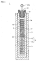
- the growth furnace is where single crystals are grown using a single crystal growth solution (hereinafter simply referred to as growth solution) by a hydrothermal method.
- a growth furnace 1 includes a furnace main body 2 and an electric furnace 3 disposed over the outer circumference of the furnace main body 2.
- the electric furnace 3 heats the furnace main body 2.
- the furnace main body 2 has a cylindrical shape open at an upper portion and closed at a bottom portion.
- An upper end opening 21 accepts a lid 22 to hermetically seal the interior of the furnace main body 2.
- the lid 22 is attached with a pressure gauge 22a to measure the pressure inside the furnace main body 2.
- the furnace main body 2 accommodates a cylindrical growth container 24 made of platinum.
- the growth container 24 has a hermetically sealed inner space 4.
- a convection regulation plate 23 is disposed.
- the convection regulation plate 23 separates the inner space 4 of the growth container 24 into a raw material section 41 on the lower side and a growth section 42 on the upper side.
- the raw material section 41 accommodates zinc-oxide single crystal raw materials 5, which are used for growth.
- the growth section 42 accommodates a plurality of seed crystals 6 supported on a single crystal growth shelf 61.
- the inner space 4 of the growth container 24 is filled with a growth solution (alkali solution).
- the single crystal raw material 5 used in this embodiment was a mixture of zinc oxide powder of 1 to 10 ⁇ m in diameter and indium oxide (In 2 O 3 ) powder of 1 to 25 ⁇ m in diameter.
- the mixture was shaped into form on a press machine, and then sintered into a sintered body in an oxygen atmosphere of 1000 to 1400°C or in atmosphere.
- the seed crystal 6 used was a plate-shaped zinc-oxide single crystal with a C surface as a main surface.
- the plate-shaped zinc-oxide single crystal was cut from a hexagonal crystal with the C surface in parallel to a (0001) surface, which is a C surface of the hexagonal crystal.
- the growth solution used was a KOH aqueous solution to which Li or a Li compound (for example, LiOH) was added.
- the growth solution may also be an aqueous solution of alkali such as NaOH, Na 2 CO 3 , or K 2 CO 3 to which Li or a Li compound was added.
- the electric furnace 3 heats the furnace main body 2.
- a heating condition is that the raw material section 41 is set at a temperature higher than a temperature of the growth section 42. The resulting difference in temperature causes natural convection of the growth solution between the raw material section 41 and the growth section 42 under high temperature and high pressure.
- the growth solution in which the single crystal raw materials 5 are dissolved moves from the raw material section 41 to the growth section 42.
- the growth solution in which the single crystal raw materials 5 are dissolved is cooled in the growth section 42 to be brought into supersaturation state. This makes the single crystal raw materials 5 deposited and grown on the seed crystals 6. This operation continues for a predetermined period of time to obtain zinc-oxide single crystals each of a predetermined size.
- the zinc-oxide single crystals thus obtained were cut so as to remove a part of each zinc-oxide single crystal grown on a (0001) surface, which is a +C surface of the corresponding seed crystal 6, or grown on a (000-1) surface, which is a -C surface of the seed crystal 6.
- This part of the zinc-oxide single crystal was used as a scintillator material.
- a scintillator made of this scintillator material was mounted in the scintillation detector.
- the scintillator materials according to comparative examples 1 to 6 are each made of a zinc-oxide single crystal grown on an M surface, which is a main surface, of a seed crystal.
- the seed crystal 6 used was a plate-shaped zinc-oxide single crystal with an M surface as a main surface.
- the plate-shaped zinc-oxide single crystal was cut from a hexagonal crystal with the M surface in parallel to a (10-10) surface, which is an M surface of the hexagonal crystal.
- a zinc-oxide single crystal was obtained by the above-described method for production, and the obtained zinc-oxide single crystal was cut to remove a part grown on the M surface. This part of the zinc-oxide single crystal was used as the scintillator materials according to comparative examples 1 to 6.
- the zinc-oxide single crystals constituting the scintillator materials according to examples 1 to 6 are higher in quality, with decreased crystal defects, than the zinc-oxide single crystals constituting the scintillator materials according to comparative examples 1 to 6.
- the zinc-oxide single crystals constituting the scintillator materials according to examples 1 to 5 are particularly superior in quality, with significantly decreased crystal defects.
- Table 1 below shows the atomic ratio between Li and In contained in the zinc-oxide single crystal of each of the scintillator materials according to examples 1 to 6 and the scintillator materials according to comparative examples 1 to 6, and shows the fluorescence lifetime of fluorescence that each scintillator material emits in response to an incident radiation.
- the Li/In (atomic ratio) shown in Table 1 is the ratio of the Li concentration (atoms/cm 3 ) to the In concentration (atoms/cm 3 ) in the zinc-oxide single crystal.
- the In concentration and the Li concentration in the zinc-oxide single crystal were analyzed by secondary ion mass spectrometry using a secondary ion mass spectrometer (ims6F, available from CAMECA).
- a streak camera (HAMAMATSU C1587) was used to measure the fluorescence lifetime of the fluorescence that the scintillator material according to each of examples 1 to 6 and each of comparative examples 1 to 6 emitted in response to an incident radiation.
- the fluorescence lifetimes of the respective components are shown as well as percentages of the components.
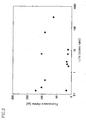
- FIG. 2 shows a relationship between the Li/In (atomic ratio) and the fluorescence lifetime.
- the plotted square dots are for the scintillator materials according to examples 1 to 6, while the plotted round dots are for the scintillator materials according to comparative examples 1 to 6.
- the case of a plurality of components constituting the emitted fluorescence is represented by the component of shortest fluorescence lifetime, showing a relationship between the shortest fluorescence lifetime and this component's Li/In (atomic ratio).
- Table 1 and FIG. 2 show that in the scintillator materials according to examples 1 to 6, each of which is made of a zinc-oxide single crystal grown on the +C surface or the -C surface of a seed crystal, the components constituting the emitted fluorescence have fluorescence lifetimes of less than 20 ps. The less than 20-ps fluorescence lifetimes of these components are observed to be shorter than any of the fluorescence lifetimes of the components of the fluorescence emitted by the scintillator materials according to comparative examples 1 to 6, each of which is grown on the M surface of a seed crystal.
- the scintillator materials according to examples 1 to 6 are mutually different in respect of the Li/In (atomic ratio) in zinc-oxide single crystal within the range of 0.15 to 11. These scintillator materials are observed to emit fluorescence made up of components of fluorescence lifetimes as short as 10.7 ps to 17.2 ps, without depending on the Li/In (atomic ratio).
- the fluorescence that the scintillator materials according to examples 1 to 6 emitted in response to an incident radiation is observed to be made up of only a single component.
- the fluorescence that the scintillator materials according to comparative examples 1 to 6 emitted in response to an incident radiation is observed to be made up of two components. Description will be made below with regard to a relationship between the intensity of the fluorescence and the fluorescence lifetime(s) of the component(s) constituting the fluorescence.
- Equation 1 The intensity of the fluorescence made up of only a single component (hereinafter referred to as component 1) is represented by the following Equation 1.
- I denotes the emission intensity with its maximum set at 1
- ⁇ 1 denotes the fluorescence lifetime of the component 1
- t denotes a period of time that elapsed after the emission intensity reached its maximum.
- I exp - t / ⁇ 1
- Equation 2 represents the intensity of fluorescence made up of the component 1 and another component (hereinafter referred to as component 2) having a longer fluorescence lifetime than the fluorescence lifetime of the component 1.
- I denotes the emission intensity with its maximum set at 1
- ⁇ 1 denotes the fluorescence lifetime of the component 1
- r 2 denotes the fluorescence lifetime of the component 2
- t denotes a period of time that elapsed after the emission intensity reached its maximum.
- C 1 denotes the presence ratio of the component 1 to the total of the component 1 and the component 2
- I C ⁇ 1 * exp - t / ⁇ ⁇ 1 + C ⁇ 2 * exp - t / ⁇ ⁇ 2
- the emission intensity of the fluorescence that the scintillator material according to comparative example 5 emits changes over time, as shown in FIG. 3A .
- the fluorescence that the scintillator material according to example 1 emits in response to an incident radiation is made up of only the component 1 of 17.2-ps fluorescence lifetime ⁇ 1 , as shown in Table 1.
- the emission intensity of the fluorescence that the scintillator material according to example 1 emits changes over time, as shown in FIG. 3B .
- the emission intensity is considered to be at 1/exp of its maximum.
- fluorescence made up of only the component 1 has the same fluorescence lifetime as the fluorescence lifetime of the component 1.
- the fluorescence lifetimes of these scintillator materials are considered to be less than 20 ps, similarly to the fluorescence lifetime of the component 1, specifically 10.7 ps to 17.2 ps.
- FIG. 3A a comparison between FIG. 3A and FIG. 3B shows that the fluorescence that the scintillator materials according to examples 1 to 6 emit is considered higher in speed of attenuation of the emission intensity than the fluorescence that the scintillator materials according to comparative examples 1 to 6 emit, resulting in shorter fluorescence lifetimes.
- fluorescence made up of only the component 1 is not a combination of the component 1 and the component 2, which has a longer fluorescence lifetime than the fluorescence lifetime of the component 1. This prevents the fluorescence from having a longer fluorescence lifetime than the fluorescence lifetime of the component 1.
- the scintillator materials according to examples 1 to 6 emitting fluorescence made up of only the component 1 the fluorescence lifetimes of these scintillator materials are considered significantly shorter than the fluorescence lifetimes of the fluorescence that is made up of the component 1 and the component 2 and that the scintillator materials according to comparative examples 1 to 6 emit.
- the fluorescence that the scintillator materials according to examples 1 to 6 emit in response to an incident radiation has a fluorescence lifetime of less than 20-ps.
- the scintillator materials according to examples 1 to 6 are considered to ensure a shorter fluorescence lifetime compared with the conventional scintillator materials according to comparative examples 1 to 6 that emit the fluorescence made up of a plurality of components having the equal to or more than 30-ps fluorescence lifetime.
- providing a scintillation detector with a scintillator made of any of the scintillator materials according to examples 1 to 6 improves the time resolution of the scintillation detector.
- the fluorescence lifetime of a zinc-oxide single crystal constituting a scintillator material is related to the lifetime of quenching, in which electrons excited from the valence band to the conduction band return to the valence band without emitting light.
- Equation 3 represents the fluorescence lifetime of the zinc-oxide single crystal, ⁇ all.
- ⁇ rad denotes the lifetime of the light emitted in process which of the electrons excited from the valence band to the conduction band return to the valence band
- ⁇ def denotes the lifetime of the quenching.
- Equation 4 the fluorescence lifetime ⁇ all of the zinc-oxide single crystal is represented by Equation 4.
- Equation 4 leads to a conclusion such that when the lifetime ⁇ def of the quenching is significantly shorter than the lifetime ⁇ rad of the emitted light, the fluorescence lifetime ⁇ all of the zinc-oxide single crystal becomes approximately equal to the lifetime ⁇ def of the quenching. That is, it is possible to say that the fluorescence lifetime ⁇ all of the zinc-oxide single crystal is determined by the lifetime ⁇ def of the quenching.
- the scintillator materials according to examples 1 to 6 have shorter lifetimes of quenching, and this presumably makes the resulting fluorescence lifetimes as short as 10.7 ps to 17.2 ps.
- the single crystal raw material 5 used is a sintered body of a mixture of zinc oxide powder and indium oxide powder, that is, a raw material containing Zn and In.
- the growth solution used is a KOH aqueous solution to which Li is added.
- the scintillator material according to the present invention may contain, in its zinc-oxide single crystal, at least one of Al, Fe, Ga, Ce, and Pr.
- the present invention is applicable to scintillation detectors that expose their scintillator to ionization radiation such as X rays, ⁇ rays, and a rays so as to cause the scintillator to emit fluorescence, and that amplify the fluorescence by a photomultiplier tube to detect the fluorescence, or the present invention is applicable to scintillator materials of such scintillation detectors.
Landscapes
- Chemical & Material Sciences (AREA)
- Engineering & Computer Science (AREA)
- Organic Chemistry (AREA)
- Materials Engineering (AREA)
- Crystallography & Structural Chemistry (AREA)
- Inorganic Chemistry (AREA)
- Physics & Mathematics (AREA)
- High Energy & Nuclear Physics (AREA)
- Metallurgy (AREA)
- Life Sciences & Earth Sciences (AREA)
- Spectroscopy & Molecular Physics (AREA)
- Molecular Biology (AREA)
- General Physics & Mathematics (AREA)
- Health & Medical Sciences (AREA)
- General Engineering & Computer Science (AREA)
- Measurement Of Radiation (AREA)
- Luminescent Compositions (AREA)
- Crystals, And After-Treatments Of Crystals (AREA)
- Nuclear Medicine (AREA)
Applications Claiming Priority (2)
| Application Number | Priority Date | Filing Date | Title |
|---|---|---|---|
| JP2010151330A JP5609327B2 (ja) | 2010-07-01 | 2010-07-01 | シンチレータ材料、及びシンチレーション検出器 |
| PCT/JP2011/063886 WO2012002171A1 (ja) | 2010-07-01 | 2011-06-17 | シンチレータ材料、及びシンチレーション検出器 |
Publications (3)
| Publication Number | Publication Date |
|---|---|
| EP2589641A1 EP2589641A1 (en) | 2013-05-08 |
| EP2589641A4 EP2589641A4 (en) | 2014-05-21 |
| EP2589641B1 true EP2589641B1 (en) | 2015-05-13 |
Family
ID=45401894
Family Applications (1)
| Application Number | Title | Priority Date | Filing Date |
|---|---|---|---|
| EP20110800636 Not-in-force EP2589641B1 (en) | 2010-07-01 | 2011-06-17 | Scintillator material and scintillation detector |
Country Status (5)
| Country | Link |
|---|---|
| US (1) | US8920677B2 (enExample) |
| EP (1) | EP2589641B1 (enExample) |
| JP (1) | JP5609327B2 (enExample) |
| CN (1) | CN102959038A (enExample) |
| WO (1) | WO2012002171A1 (enExample) |
Families Citing this family (6)
| Publication number | Priority date | Publication date | Assignee | Title |
|---|---|---|---|---|
| JP6032590B2 (ja) * | 2012-04-04 | 2016-11-30 | 株式会社福田結晶技術研究所 | 酸化亜鉛単結晶の製造方法 |
| JP5594380B2 (ja) * | 2013-01-25 | 2014-09-24 | 株式会社大真空 | シンチレータ、放射線検出器、放射線検査装置、α線検出器、及びシンチレータの製造方法 |
| CN107209275B (zh) * | 2014-07-23 | 2019-08-20 | 皇家飞利浦有限公司 | 用于表征闪烁体材料的表征装置 |
| JP6623412B2 (ja) * | 2015-04-23 | 2019-12-25 | 株式会社福田結晶技術研究所 | 酸化亜鉛結晶の製造方法、酸化亜鉛結晶、シンチレータ材料及びシンチレータ検出器 |
| JP6676372B2 (ja) * | 2015-12-28 | 2020-04-08 | 株式会社S−Nanotech Co−Creation | シンチレータ及び電子検出器 |
| US10490397B1 (en) * | 2018-07-18 | 2019-11-26 | Thermo Finnigan Llc | Methods and systems for detection of ion spatial distribution |
Family Cites Families (8)
| Publication number | Priority date | Publication date | Assignee | Title |
|---|---|---|---|---|
| JPH101396A (ja) | 1996-06-14 | 1998-01-06 | Mitsubishi Heavy Ind Ltd | 発光材料およびその製造方法 |
| JP2003277191A (ja) | 2002-03-26 | 2003-10-02 | Japan Science & Technology Corp | Yb混晶酸化物単結晶からなるシンチレータ用発光材料 |
| EP1754981A4 (en) | 2004-05-24 | 2009-10-21 | Fukuda X Tal Lab | ZNO-EINKRISTALL AS A SUPERSCHELLEN SZINTILLATOR AND MANUFACTURING METHOD THEREFOR |
| EP1997941B1 (en) * | 2006-03-01 | 2014-12-17 | Mitsubishi Gas Chemical Company, Inc. | PROCESS FOR PRODUCING ZnO SINGLE CRYSTAL ACCORDING TO METHOD OF LIQUID PHASE GROWTH |
| JP2009234825A (ja) * | 2008-03-26 | 2009-10-15 | Mitsubishi Gas Chem Co Inc | ZnO単結晶の製造方法およびそれによって得られた自立ZnO単結晶ウエファー |
| JP5519492B2 (ja) * | 2008-04-26 | 2014-06-11 | 森 竜平 | 酸化亜鉛単結晶基板の製造方法及びその方法により育成された単結晶基板並びにその基板上に成膜した半導体発光素子 |
| JP2009286856A (ja) * | 2008-05-27 | 2009-12-10 | Fukuda Crystal Laboratory | シンチレータ材料とその製造方法、及び、電離放射線検出器 |
| JP5251488B2 (ja) | 2008-12-24 | 2013-07-31 | パナソニック株式会社 | 冷蔵庫 |
-
2010
- 2010-07-01 JP JP2010151330A patent/JP5609327B2/ja not_active Expired - Fee Related
-
2011
- 2011-06-17 EP EP20110800636 patent/EP2589641B1/en not_active Not-in-force
- 2011-06-17 WO PCT/JP2011/063886 patent/WO2012002171A1/ja not_active Ceased
- 2011-06-17 US US13/703,713 patent/US8920677B2/en not_active Expired - Fee Related
- 2011-06-17 CN CN201180029633XA patent/CN102959038A/zh active Pending
Also Published As
| Publication number | Publication date |
|---|---|
| WO2012002171A1 (ja) | 2012-01-05 |
| JP5609327B2 (ja) | 2014-10-22 |
| US20130087739A1 (en) | 2013-04-11 |
| EP2589641A4 (en) | 2014-05-21 |
| CN102959038A (zh) | 2013-03-06 |
| US8920677B2 (en) | 2014-12-30 |
| EP2589641A1 (en) | 2013-05-08 |
| JP2012012527A (ja) | 2012-01-19 |
Similar Documents
| Publication | Publication Date | Title |
|---|---|---|
| EP2589641B1 (en) | Scintillator material and scintillation detector | |
| US10591617B2 (en) | Perovskite-type halides and methods thereof | |
| US8709155B1 (en) | Method of preparing scintillation materials with reduced afterglow | |
| US7692153B2 (en) | Scintillator crystal and radiation detector | |
| EP2256177B1 (en) | Scintillator for neutron detection and neutron detector | |
| Nakamura et al. | Scintillation, TSL and RPL properties of MgF2 transparent ceramic and single crystal | |
| EP2746362B1 (en) | Scintillator | |
| Futami et al. | Optical and scintillation properties of Sc2O3, Y2O3 and Lu2O3 transparent ceramics synthesized by SPS method | |
| US20120119092A1 (en) | Scintillating material having low afterglow | |
| Kobayashi et al. | Scintillation characteristics of CsPbCl3 single crystals | |
| US7759645B1 (en) | Scintillation materials with reduced afterglow and method of preparation | |
| EP3109294B1 (en) | Scintillator | |
| EP1754981A1 (en) | ZnO SINGLE CRYSTAL AS SUPER HIGH SPEED SCINTILLATOR AND METHOD FOR PREPARATION THEREOF | |
| Vaněček et al. | Ultraviolet cross-luminescence in ternary chlorides of alkali and alkaline-earth metals | |
| Nakamura et al. | Radio-photoluminescence in non-doped K2CO3 ceramics | |
| EP2685286A1 (en) | Neutron beam detection device | |
| Wu et al. | Defect engineering by codoping in KCaI 3: Eu 2+ single-crystalline scintillators | |
| US20200318005A1 (en) | Rare-earth halide scintillating material and application thereof | |
| Kawaguchi et al. | Scintillation Properties of LiF/(K 0.75 Rb 0.25) 2 CuCl 3 Composites for Thermal Neutron Detection. | |
| Yang et al. | Crystal growth and scintillation properties of Cs3EuI5 crystals | |
| Rowe | High-Performance Doped Strontium Iodide Crystal Growth Using a Modified Bridgman Method | |
| Rutstrom | Development of Novel Cesium Chloride-based Ultrafast Inorganic Scintillators for Fast Timing Radiation Detection Applications | |
| WO2014115440A1 (ja) | シンチレータ、放射線検出器、放射線検査装置、α線検出器、及びシンチレータの製造方法 | |
| Trevisani et al. | Fast UV luminescence of Pr3+-doped calcium lutetium whitlockite | |
| Yang et al. | Synthesis and scintillation properties of CsGd2Cl7: Ce3+ for gamma ray and neutron detection |
Legal Events
| Date | Code | Title | Description |
|---|---|---|---|
| PUAI | Public reference made under article 153(3) epc to a published international application that has entered the european phase |
Free format text: ORIGINAL CODE: 0009012 |
|
| 17P | Request for examination filed |
Effective date: 20130201 |
|
| AK | Designated contracting states |
Kind code of ref document: A1 Designated state(s): AL AT BE BG CH CY CZ DE DK EE ES FI FR GB GR HR HU IE IS IT LI LT LU LV MC MK MT NL NO PL PT RO RS SE SI SK SM TR |
|
| DAX | Request for extension of the european patent (deleted) | ||
| A4 | Supplementary search report drawn up and despatched |
Effective date: 20140424 |
|
| RIC1 | Information provided on ipc code assigned before grant |
Ipc: C09K 11/54 20060101AFI20140416BHEP Ipc: C30B 29/16 20060101ALI20140416BHEP Ipc: C30B 7/10 20060101ALI20140416BHEP |
|
| REG | Reference to a national code |
Ref country code: DE Ref legal event code: R079 Ref document number: 602011016507 Country of ref document: DE Free format text: PREVIOUS MAIN CLASS: C09K0011000000 Ipc: C09K0011620000 |
|
| GRAP | Despatch of communication of intention to grant a patent |
Free format text: ORIGINAL CODE: EPIDOSNIGR1 |
|
| RIC1 | Information provided on ipc code assigned before grant |
Ipc: C30B 29/16 20060101ALI20141212BHEP Ipc: C30B 7/10 20060101ALI20141212BHEP Ipc: C09K 11/62 20060101AFI20141212BHEP |
|
| INTG | Intention to grant announced |
Effective date: 20150115 |
|
| GRAS | Grant fee paid |
Free format text: ORIGINAL CODE: EPIDOSNIGR3 |
|
| GRAA | (expected) grant |
Free format text: ORIGINAL CODE: 0009210 |
|
| AK | Designated contracting states |
Kind code of ref document: B1 Designated state(s): AL AT BE BG CH CY CZ DE DK EE ES FI FR GB GR HR HU IE IS IT LI LT LU LV MC MK MT NL NO PL PT RO RS SE SI SK SM TR |
|
| REG | Reference to a national code |
Ref country code: GB Ref legal event code: FG4D |
|
| REG | Reference to a national code |
Ref country code: CH Ref legal event code: EP |
|
| REG | Reference to a national code |
Ref country code: IE Ref legal event code: FG4D |
|
| REG | Reference to a national code |
Ref country code: AT Ref legal event code: REF Ref document number: 726847 Country of ref document: AT Kind code of ref document: T Effective date: 20150615 |
|
| REG | Reference to a national code |
Ref country code: DE Ref legal event code: R096 Ref document number: 602011016507 Country of ref document: DE Effective date: 20150625 |
|
| REG | Reference to a national code |
Ref country code: AT Ref legal event code: MK05 Ref document number: 726847 Country of ref document: AT Kind code of ref document: T Effective date: 20150513 |
|
| REG | Reference to a national code |
Ref country code: NL Ref legal event code: MP Effective date: 20150513 |
|
| REG | Reference to a national code |
Ref country code: LT Ref legal event code: MG4D |
|
| PG25 | Lapsed in a contracting state [announced via postgrant information from national office to epo] |
Ref country code: ES Free format text: LAPSE BECAUSE OF FAILURE TO SUBMIT A TRANSLATION OF THE DESCRIPTION OR TO PAY THE FEE WITHIN THE PRESCRIBED TIME-LIMIT Effective date: 20150513 Ref country code: LT Free format text: LAPSE BECAUSE OF FAILURE TO SUBMIT A TRANSLATION OF THE DESCRIPTION OR TO PAY THE FEE WITHIN THE PRESCRIBED TIME-LIMIT Effective date: 20150513 Ref country code: NO Free format text: LAPSE BECAUSE OF FAILURE TO SUBMIT A TRANSLATION OF THE DESCRIPTION OR TO PAY THE FEE WITHIN THE PRESCRIBED TIME-LIMIT Effective date: 20150813 Ref country code: PT Free format text: LAPSE BECAUSE OF FAILURE TO SUBMIT A TRANSLATION OF THE DESCRIPTION OR TO PAY THE FEE WITHIN THE PRESCRIBED TIME-LIMIT Effective date: 20150914 Ref country code: HR Free format text: LAPSE BECAUSE OF FAILURE TO SUBMIT A TRANSLATION OF THE DESCRIPTION OR TO PAY THE FEE WITHIN THE PRESCRIBED TIME-LIMIT Effective date: 20150513 Ref country code: FI Free format text: LAPSE BECAUSE OF FAILURE TO SUBMIT A TRANSLATION OF THE DESCRIPTION OR TO PAY THE FEE WITHIN THE PRESCRIBED TIME-LIMIT Effective date: 20150513 |
|
| PG25 | Lapsed in a contracting state [announced via postgrant information from national office to epo] |
Ref country code: BG Free format text: LAPSE BECAUSE OF FAILURE TO SUBMIT A TRANSLATION OF THE DESCRIPTION OR TO PAY THE FEE WITHIN THE PRESCRIBED TIME-LIMIT Effective date: 20150813 Ref country code: LV Free format text: LAPSE BECAUSE OF FAILURE TO SUBMIT A TRANSLATION OF THE DESCRIPTION OR TO PAY THE FEE WITHIN THE PRESCRIBED TIME-LIMIT Effective date: 20150513 Ref country code: GR Free format text: LAPSE BECAUSE OF FAILURE TO SUBMIT A TRANSLATION OF THE DESCRIPTION OR TO PAY THE FEE WITHIN THE PRESCRIBED TIME-LIMIT Effective date: 20150814 Ref country code: RS Free format text: LAPSE BECAUSE OF FAILURE TO SUBMIT A TRANSLATION OF THE DESCRIPTION OR TO PAY THE FEE WITHIN THE PRESCRIBED TIME-LIMIT Effective date: 20150513 Ref country code: AT Free format text: LAPSE BECAUSE OF FAILURE TO SUBMIT A TRANSLATION OF THE DESCRIPTION OR TO PAY THE FEE WITHIN THE PRESCRIBED TIME-LIMIT Effective date: 20150513 Ref country code: IS Free format text: LAPSE BECAUSE OF FAILURE TO SUBMIT A TRANSLATION OF THE DESCRIPTION OR TO PAY THE FEE WITHIN THE PRESCRIBED TIME-LIMIT Effective date: 20150913 |
|
| PG25 | Lapsed in a contracting state [announced via postgrant information from national office to epo] |
Ref country code: DK Free format text: LAPSE BECAUSE OF FAILURE TO SUBMIT A TRANSLATION OF THE DESCRIPTION OR TO PAY THE FEE WITHIN THE PRESCRIBED TIME-LIMIT Effective date: 20150513 Ref country code: EE Free format text: LAPSE BECAUSE OF FAILURE TO SUBMIT A TRANSLATION OF THE DESCRIPTION OR TO PAY THE FEE WITHIN THE PRESCRIBED TIME-LIMIT Effective date: 20150513 Ref country code: IT Free format text: LAPSE BECAUSE OF FAILURE TO SUBMIT A TRANSLATION OF THE DESCRIPTION OR TO PAY THE FEE WITHIN THE PRESCRIBED TIME-LIMIT Effective date: 20150513 |
|
| REG | Reference to a national code |
Ref country code: CH Ref legal event code: PL |
|
| REG | Reference to a national code |
Ref country code: DE Ref legal event code: R097 Ref document number: 602011016507 Country of ref document: DE |
|
| PG25 | Lapsed in a contracting state [announced via postgrant information from national office to epo] |
Ref country code: PL Free format text: LAPSE BECAUSE OF FAILURE TO SUBMIT A TRANSLATION OF THE DESCRIPTION OR TO PAY THE FEE WITHIN THE PRESCRIBED TIME-LIMIT Effective date: 20150513 Ref country code: RO Free format text: LAPSE BECAUSE OF NON-PAYMENT OF DUE FEES Effective date: 20150513 Ref country code: MC Free format text: LAPSE BECAUSE OF FAILURE TO SUBMIT A TRANSLATION OF THE DESCRIPTION OR TO PAY THE FEE WITHIN THE PRESCRIBED TIME-LIMIT Effective date: 20150513 Ref country code: CZ Free format text: LAPSE BECAUSE OF FAILURE TO SUBMIT A TRANSLATION OF THE DESCRIPTION OR TO PAY THE FEE WITHIN THE PRESCRIBED TIME-LIMIT Effective date: 20150513 Ref country code: SK Free format text: LAPSE BECAUSE OF FAILURE TO SUBMIT A TRANSLATION OF THE DESCRIPTION OR TO PAY THE FEE WITHIN THE PRESCRIBED TIME-LIMIT Effective date: 20150513 |
|
| PLBE | No opposition filed within time limit |
Free format text: ORIGINAL CODE: 0009261 |
|
| STAA | Information on the status of an ep patent application or granted ep patent |
Free format text: STATUS: NO OPPOSITION FILED WITHIN TIME LIMIT |
|
| REG | Reference to a national code |
Ref country code: IE Ref legal event code: MM4A |
|
| REG | Reference to a national code |
Ref country code: FR Ref legal event code: ST Effective date: 20160229 |
|
| 26N | No opposition filed |
Effective date: 20160216 |
|
| GBPC | Gb: european patent ceased through non-payment of renewal fee |
Effective date: 20150813 |
|
| PG25 | Lapsed in a contracting state [announced via postgrant information from national office to epo] |
Ref country code: LI Free format text: LAPSE BECAUSE OF NON-PAYMENT OF DUE FEES Effective date: 20150630 Ref country code: IE Free format text: LAPSE BECAUSE OF NON-PAYMENT OF DUE FEES Effective date: 20150617 Ref country code: CH Free format text: LAPSE BECAUSE OF NON-PAYMENT OF DUE FEES Effective date: 20150630 |
|
| PG25 | Lapsed in a contracting state [announced via postgrant information from national office to epo] |
Ref country code: SI Free format text: LAPSE BECAUSE OF FAILURE TO SUBMIT A TRANSLATION OF THE DESCRIPTION OR TO PAY THE FEE WITHIN THE PRESCRIBED TIME-LIMIT Effective date: 20150513 Ref country code: FR Free format text: LAPSE BECAUSE OF NON-PAYMENT OF DUE FEES Effective date: 20150713 |
|
| PG25 | Lapsed in a contracting state [announced via postgrant information from national office to epo] |
Ref country code: GB Free format text: LAPSE BECAUSE OF NON-PAYMENT OF DUE FEES Effective date: 20150813 |
|
| PG25 | Lapsed in a contracting state [announced via postgrant information from national office to epo] |
Ref country code: BE Free format text: LAPSE BECAUSE OF FAILURE TO SUBMIT A TRANSLATION OF THE DESCRIPTION OR TO PAY THE FEE WITHIN THE PRESCRIBED TIME-LIMIT Effective date: 20150513 |
|
| PG25 | Lapsed in a contracting state [announced via postgrant information from national office to epo] |
Ref country code: MT Free format text: LAPSE BECAUSE OF FAILURE TO SUBMIT A TRANSLATION OF THE DESCRIPTION OR TO PAY THE FEE WITHIN THE PRESCRIBED TIME-LIMIT Effective date: 20150513 |
|
| PG25 | Lapsed in a contracting state [announced via postgrant information from national office to epo] |
Ref country code: SM Free format text: LAPSE BECAUSE OF FAILURE TO SUBMIT A TRANSLATION OF THE DESCRIPTION OR TO PAY THE FEE WITHIN THE PRESCRIBED TIME-LIMIT Effective date: 20150513 Ref country code: HU Free format text: LAPSE BECAUSE OF FAILURE TO SUBMIT A TRANSLATION OF THE DESCRIPTION OR TO PAY THE FEE WITHIN THE PRESCRIBED TIME-LIMIT; INVALID AB INITIO Effective date: 20110617 |
|
| PG25 | Lapsed in a contracting state [announced via postgrant information from national office to epo] |
Ref country code: NL Free format text: LAPSE BECAUSE OF FAILURE TO SUBMIT A TRANSLATION OF THE DESCRIPTION OR TO PAY THE FEE WITHIN THE PRESCRIBED TIME-LIMIT Effective date: 20150513 Ref country code: CY Free format text: LAPSE BECAUSE OF FAILURE TO SUBMIT A TRANSLATION OF THE DESCRIPTION OR TO PAY THE FEE WITHIN THE PRESCRIBED TIME-LIMIT Effective date: 20150513 Ref country code: SE Free format text: LAPSE BECAUSE OF FAILURE TO SUBMIT A TRANSLATION OF THE DESCRIPTION OR TO PAY THE FEE WITHIN THE PRESCRIBED TIME-LIMIT Effective date: 20150513 |
|
| PG25 | Lapsed in a contracting state [announced via postgrant information from national office to epo] |
Ref country code: TR Free format text: LAPSE BECAUSE OF FAILURE TO SUBMIT A TRANSLATION OF THE DESCRIPTION OR TO PAY THE FEE WITHIN THE PRESCRIBED TIME-LIMIT Effective date: 20150513 |
|
| PG25 | Lapsed in a contracting state [announced via postgrant information from national office to epo] |
Ref country code: LU Free format text: LAPSE BECAUSE OF NON-PAYMENT OF DUE FEES Effective date: 20150617 |
|
| PG25 | Lapsed in a contracting state [announced via postgrant information from national office to epo] |
Ref country code: MK Free format text: LAPSE BECAUSE OF FAILURE TO SUBMIT A TRANSLATION OF THE DESCRIPTION OR TO PAY THE FEE WITHIN THE PRESCRIBED TIME-LIMIT Effective date: 20150513 |
|
| PG25 | Lapsed in a contracting state [announced via postgrant information from national office to epo] |
Ref country code: AL Free format text: LAPSE BECAUSE OF FAILURE TO SUBMIT A TRANSLATION OF THE DESCRIPTION OR TO PAY THE FEE WITHIN THE PRESCRIBED TIME-LIMIT Effective date: 20150513 |
|
| PGFP | Annual fee paid to national office [announced via postgrant information from national office to epo] |
Ref country code: DE Payment date: 20200618 Year of fee payment: 10 |
|
| REG | Reference to a national code |
Ref country code: DE Ref legal event code: R119 Ref document number: 602011016507 Country of ref document: DE |
|
| PG25 | Lapsed in a contracting state [announced via postgrant information from national office to epo] |
Ref country code: DE Free format text: LAPSE BECAUSE OF NON-PAYMENT OF DUE FEES Effective date: 20220101 |