EP2587902A1 - Kommunikationsvorrichtung und produktionsverfahren für ein kommunikationsvorrichtungsgehäuse - Google Patents
Kommunikationsvorrichtung und produktionsverfahren für ein kommunikationsvorrichtungsgehäuse Download PDFInfo
- Publication number
- EP2587902A1 EP2587902A1 EP11798163.9A EP11798163A EP2587902A1 EP 2587902 A1 EP2587902 A1 EP 2587902A1 EP 11798163 A EP11798163 A EP 11798163A EP 2587902 A1 EP2587902 A1 EP 2587902A1
- Authority
- EP
- European Patent Office
- Prior art keywords
- set forth
- communication device
- enclosure
- nonferrous metal
- odu
- Prior art date
- Legal status (The legal status is an assumption and is not a legal conclusion. Google has not performed a legal analysis and makes no representation as to the accuracy of the status listed.)
- Withdrawn
Links
- 238000004891 communication Methods 0.000 title claims abstract description 48
- 238000004519 manufacturing process Methods 0.000 title description 2
- 229910052751 metal Inorganic materials 0.000 claims abstract description 59
- 239000002184 metal Substances 0.000 claims abstract description 58
- 239000002245 particle Substances 0.000 claims abstract description 51
- 239000000843 powder Substances 0.000 claims abstract description 51
- 230000005540 biological transmission Effects 0.000 claims abstract description 29
- 239000003973 paint Substances 0.000 claims abstract description 18
- 229910000838 Al alloy Inorganic materials 0.000 claims description 22
- 238000000034 method Methods 0.000 claims description 16
- 239000010935 stainless steel Substances 0.000 claims description 11
- 229910001220 stainless steel Inorganic materials 0.000 claims description 11
- 230000008569 process Effects 0.000 claims description 8
- TWNQGVIAIRXVLR-UHFFFAOYSA-N oxo(oxoalumanyloxy)alumane Chemical compound O=[Al]O[Al]=O TWNQGVIAIRXVLR-UHFFFAOYSA-N 0.000 claims description 6
- 239000000203 mixture Substances 0.000 claims description 5
- 239000011324 bead Substances 0.000 claims description 4
- 239000011521 glass Substances 0.000 claims description 4
- 239000011248 coating agent Substances 0.000 abstract description 6
- 238000000576 coating method Methods 0.000 abstract description 6
- 239000002344 surface layer Substances 0.000 description 10
- 238000010586 diagram Methods 0.000 description 9
- 238000005260 corrosion Methods 0.000 description 8
- 230000007797 corrosion Effects 0.000 description 8
- 239000000463 material Substances 0.000 description 8
- 239000007789 gas Substances 0.000 description 6
- 238000002844 melting Methods 0.000 description 6
- FAPWRFPIFSIZLT-UHFFFAOYSA-M Sodium chloride Chemical compound [Na+].[Cl-] FAPWRFPIFSIZLT-UHFFFAOYSA-M 0.000 description 5
- 230000008018 melting Effects 0.000 description 5
- 239000011780 sodium chloride Substances 0.000 description 5
- 239000007921 spray Substances 0.000 description 5
- RAHZWNYVWXNFOC-UHFFFAOYSA-N Sulphur dioxide Chemical compound O=S=O RAHZWNYVWXNFOC-UHFFFAOYSA-N 0.000 description 4
- 230000002411 adverse Effects 0.000 description 3
- 229910052782 aluminium Inorganic materials 0.000 description 3
- XAGFODPZIPBFFR-UHFFFAOYSA-N aluminium Chemical compound [Al] XAGFODPZIPBFFR-UHFFFAOYSA-N 0.000 description 3
- 230000007613 environmental effect Effects 0.000 description 3
- 238000009434 installation Methods 0.000 description 3
- 230000003746 surface roughness Effects 0.000 description 3
- 238000011282 treatment Methods 0.000 description 3
- 229910001297 Zn alloy Inorganic materials 0.000 description 2
- PNEYBMLMFCGWSK-UHFFFAOYSA-N aluminium oxide Inorganic materials [O-2].[O-2].[O-2].[Al+3].[Al+3] PNEYBMLMFCGWSK-UHFFFAOYSA-N 0.000 description 2
- 239000010410 layer Substances 0.000 description 2
- 150000002739 metals Chemical class 0.000 description 2
- 239000003960 organic solvent Substances 0.000 description 2
- 239000011347 resin Substances 0.000 description 2
- 229920005989 resin Polymers 0.000 description 2
- UFHFLCQGNIYNRP-UHFFFAOYSA-N Hydrogen Chemical compound [H][H] UFHFLCQGNIYNRP-UHFFFAOYSA-N 0.000 description 1
- NINIDFKCEFEMDL-UHFFFAOYSA-N Sulfur Chemical compound [S] NINIDFKCEFEMDL-UHFFFAOYSA-N 0.000 description 1
- 238000005299 abrasion Methods 0.000 description 1
- 238000010521 absorption reaction Methods 0.000 description 1
- 229910045601 alloy Inorganic materials 0.000 description 1
- 239000000956 alloy Substances 0.000 description 1
- QVGXLLKOCUKJST-UHFFFAOYSA-N atomic oxygen Chemical compound [O] QVGXLLKOCUKJST-UHFFFAOYSA-N 0.000 description 1
- 238000001816 cooling Methods 0.000 description 1
- 238000005520 cutting process Methods 0.000 description 1
- 230000003247 decreasing effect Effects 0.000 description 1
- 230000000694 effects Effects 0.000 description 1
- 239000000284 extract Substances 0.000 description 1
- 230000005484 gravity Effects 0.000 description 1
- 238000010438 heat treatment Methods 0.000 description 1
- 230000003116 impacting effect Effects 0.000 description 1
- 229910044991 metal oxide Inorganic materials 0.000 description 1
- 150000004706 metal oxides Chemical class 0.000 description 1
- 238000010295 mobile communication Methods 0.000 description 1
- 229910052760 oxygen Inorganic materials 0.000 description 1
- 239000001301 oxygen Substances 0.000 description 1
- 238000010791 quenching Methods 0.000 description 1
- 230000000171 quenching effect Effects 0.000 description 1
- 230000005855 radiation Effects 0.000 description 1
- 230000009467 reduction Effects 0.000 description 1
- 238000005480 shot peening Methods 0.000 description 1
- 238000007711 solidification Methods 0.000 description 1
- 230000008023 solidification Effects 0.000 description 1
- 238000005507 spraying Methods 0.000 description 1
- 229910052717 sulfur Inorganic materials 0.000 description 1
- 239000011593 sulfur Substances 0.000 description 1
- 238000004381 surface treatment Methods 0.000 description 1
Images




Classifications
-
- H—ELECTRICITY
- H05—ELECTRIC TECHNIQUES NOT OTHERWISE PROVIDED FOR
- H05K—PRINTED CIRCUITS; CASINGS OR CONSTRUCTIONAL DETAILS OF ELECTRIC APPARATUS; MANUFACTURE OF ASSEMBLAGES OF ELECTRICAL COMPONENTS
- H05K5/00—Casings, cabinets or drawers for electric apparatus
- H05K5/04—Metal casings
-
- B—PERFORMING OPERATIONS; TRANSPORTING
- B24—GRINDING; POLISHING
- B24C—ABRASIVE OR RELATED BLASTING WITH PARTICULATE MATERIAL
- B24C1/00—Methods for use of abrasive blasting for producing particular effects; Use of auxiliary equipment in connection with such methods
- B24C1/10—Methods for use of abrasive blasting for producing particular effects; Use of auxiliary equipment in connection with such methods for compacting surfaces, e.g. shot-peening
-
- C—CHEMISTRY; METALLURGY
- C23—COATING METALLIC MATERIAL; COATING MATERIAL WITH METALLIC MATERIAL; CHEMICAL SURFACE TREATMENT; DIFFUSION TREATMENT OF METALLIC MATERIAL; COATING BY VACUUM EVAPORATION, BY SPUTTERING, BY ION IMPLANTATION OR BY CHEMICAL VAPOUR DEPOSITION, IN GENERAL; INHIBITING CORROSION OF METALLIC MATERIAL OR INCRUSTATION IN GENERAL
- C23C—COATING METALLIC MATERIAL; COATING MATERIAL WITH METALLIC MATERIAL; SURFACE TREATMENT OF METALLIC MATERIAL BY DIFFUSION INTO THE SURFACE, BY CHEMICAL CONVERSION OR SUBSTITUTION; COATING BY VACUUM EVAPORATION, BY SPUTTERING, BY ION IMPLANTATION OR BY CHEMICAL VAPOUR DEPOSITION, IN GENERAL
- C23C24/00—Coating starting from inorganic powder
- C23C24/08—Coating starting from inorganic powder by application of heat or pressure and heat
- C23C24/10—Coating starting from inorganic powder by application of heat or pressure and heat with intermediate formation of a liquid phase in the layer
- C23C24/103—Coating with metallic material, i.e. metals or metal alloys, optionally comprising hard particles, e.g. oxides, carbides or nitrides
- C23C24/106—Coating with metal alloys or metal elements only
-
- H—ELECTRICITY
- H05—ELECTRIC TECHNIQUES NOT OTHERWISE PROVIDED FOR
- H05K—PRINTED CIRCUITS; CASINGS OR CONSTRUCTIONAL DETAILS OF ELECTRIC APPARATUS; MANUFACTURE OF ASSEMBLAGES OF ELECTRICAL COMPONENTS
- H05K5/00—Casings, cabinets or drawers for electric apparatus
- H05K5/02—Details
- H05K5/0217—Mechanical details of casings
- H05K5/0243—Mechanical details of casings for decorative purposes
Definitions
- the present invention relates to a communication device installed outdoors, in particular, to a structure and a producing method for an enclosure that accommodates a transmission section and a reception section that make up the communication device.
- Radio communication systems represented by portable telephone systems form an access network that connects radio base stations.
- Such an access network connects radio base stations using cable communication or radio communication.
- Radio communication performed between radio base stations uses microwave radio communication devices.
- Such radio communication devices need to be installed at high places such as pylons or rooftops of buildings such that radio communication is not obstructed.
- Such radio communication devices are categorized as outdoor devices installed close to antennas that are also installed at high places (hereinafter these outdoor devices units are referred to as ODUs) and indoor devices installed apart from the ODUs (hereinafter these indoor devices units are referred to as IDUs).
- the ODU and the IDU are connected by a coaxial cable or the like (refer to Patent Literature 1). Since the ODU along with the antenna is installed a high outdoor elevation, it's functionality is limited to transmitting and receiving a signal to and from the antenna which results in the ODU being small and light. In contrast, the IDU is provided with more complicated functions that modulate, demodulate, and process a signal and is installed indoors such that the IDU itself can be easily maintained and such that its reliability is improved.
- the ODU In such a radio communication device that communicates between base stations, the ODU is installed outdoors where installation environment is particularly severe, occasionally, in the desert, cold area, or seashore. Moreover, the ODU tends to be installed at a place where it is very difficult to frequently maintain and inspect (for example, a high place such as a pylon). Thus, the ODU needs to be able to designed so that it can operate in a very adverse environment. To satisfy such requirements, precision electronic parts such as a transmission circuit and a reception circuit that make up the ODU are contained in a rigid metal enclosure. In addition, the surface of the metal enclosure is normally coated with a resin paint so as to ensure durability and resistance to corrosion.
- Such a coating of paint can slow down the speed with which the metal enclosure, that forms the ODU, corrodes and thus enhance the reliability of the device. Moreover, if the enclosure is coated with a white paint, it can prevent absorption of sun light to which the metal enclosure is exposed so as to impede heat from reaching the inside of the ODU. Such paint coating is however expensive.
- the precision electronic parts of the ODU would be adversely affected due to corrosion of the enclosure and so forth.
- the enclosure of the ODU is cast, it can be quantitatively produced and the cost reduced.
- a metal flow mark, cast mark, or the like might appear on the surface of the enclosure.
- such an appearance on the surface of the enclosure would have a problem from a point of view of product value.
- Patent Literature 1 JP2006-197343A , Publication
- An object of the present invention is to ensure that metal enclosure that contains a transmission section and a reception section of an ODU is resistant to the adverse effects of a severe environment without it being necessary to apply a coating of paint to the enclosure.
- An aspect of the present invention is a communication device installed outdoors, including a transmission section that transmits a signal; a reception section that receives a signal; and an enclosure that contains the transmission section and the reception section,
- the enclosure is made of a nonferrous metal and an outer surface of the nonferrous metal is not coated with paint, but a concave and convex pattern of an impact mark of powder particle is successively formed thereon.
- Another aspect of the present invention is a method for producing an enclosure of a communication device installed outdoors, including forming said enclosure of a nonferrous metal by a die cast process; having powder particles impact an outer surface of said enclosure that has been formed; and successively forming a concave and convex pattern of an impact mark of the powder particles on said outer surface.
- Outdoor radio communication device 1A Cover 1B Case 2 Nonferrous metal 2a Concave and convex pattern 2b Oxide layer 3 Antenna 4 Pole 5 Joint portion 6 Handle 11 A station (base station) 12, 22 IDU 13, 23 ODU 14,24 Antenna 15,25 Coaxial cable 21 B station (base station) 31 Multiplexer circuit 32 Transmission and reception circuit 33 Control circuit
- Fig. 1 is a perspective view showing that an outdoor radio communication device (ODU) according to an embodiment of the present invention has been installed.
- ODU 1 according to this embodiment shown in the drawing comprises a transmission section (not shown) that transmits a radio signal; a reception section (not shown) that receives a radio signal; and an enclosure that contains at least these sections.
- Assembled in ODU 1 is, for example, antenna 3 as shown in Fig. 1 .
- Antenna 3 transmits a radio signal that is output from the transmission section to the outside and receives a radio signal that is output to the reception section from the outside.
- ODU 1 has a joint portion (refer to reference numeral 5 shown in Fig. 3 ) that connects ODU 1 to antenna 3.
- ODU 1 is secured to pole 4 mounted for example on the rooftop of a building.
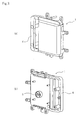
- Fig. 2 shows ODU 1: Fig 2(a) is a front view of ODU 1 and Fig. 2(b) is a rear view of ODU 1.
- Fig. 3(a) is a perspective view showing the front side of ODU 1 and Fig. 3(b) is a perspective view showing the rear side of ODU 1.
- the enclosure of ODU 1 shown in these drawings is made up of cover 1A and case 1B.
- the enclosure contains the transmission section and the reception section.
- ODU 1 also has handle 6 that allows the user to easily carry ODU 1 itself and to easily set the transmission and reception directions. Handle 6 may be integrated with case 1B. If the enclosure and handle 6 are integrated, the number of parts of ODU 1 can be decreased.
- the enclosure is made of a nonferrous metal. Although the enclosure may be produced by cutting a material, if the enclosure is quantitatively produced, it is formed by a die cast process.
- the material of the enclosure is a nonferrous metal. Examples of the material of the enclosure include aluminum, an aluminum alloy, and a zinc alloy. Since these nonferrous metals are light and can be easily machined and especially easily produced by a die cast process, they are suitable for the enclosure of ODU 1. When the enclosure of ODU 1 is formed by the die cast process, it can be easily quantitatively produced and its cost can be reduced.
- powder particles are uniformly sprayed at a high speed on the surface of the enclosure of the ODU instead of the surface being coated with paint such that a concave and convex pattern is successively formed on the entire surface of a nonferrous metal.
- the concave and convex pattern is the impact mark of the powder particles.
- a concave and convex pattern is formed on the surface of a nonferrous metal that forms handle 6 in the same manner as the enclosure. If handle 6 and the enclosure are integratedly formed, they could be effectively treated at once.
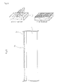
- Fig. 4 shows the state in which a concave and convex pattern is formed as described above.
- Examples of the material of the powder particles include stainless steel, glass beads, and aluminum oxide (alumina).
- the powder particles may be sprayed by an impeller type spray device or an air nozzle type shot peening device.
- the nonferrous metal that forms the enclosure of ODU 1 is an aluminum alloy and the powder particles that are sprayed thereto is powder particles of stainless steel, physical treatments for a surface layer of an aluminum alloy will be described.
- Fig. 5 is a sectional view schematically showing the outer surface and inside of a nonferrous metal on which a concave and convex pattern is formed in such a manner. As shown in the drawing, concave and convex pattern 2a is formed on the outer surface of nonferrous metal 2 and the outer surface is re-melted and modified into oxide layer 2b.
- the nonferrous metal that makes up the enclosure of the ODU is an aluminum alloy
- an oxide film mainly containing aluminum oxide (Al 2 O 3 ) is formed on the surface of the aluminum alloy.
- Al 2 O 3 aluminum oxide
- Such an oxide itself has a high resistance to corrosion.
- the oxide film formed on the surface due to the heat that is generated when the powder particles impact a surface is thicker than an oxide film that forms naturally on the surface.
- the outer surface layer of the aluminum alloy is microscopically formed due to quick heating and quick cooling.
- the metal composition of the surface layer of the aluminum alloy is more microscopically formed than the inside of the aluminum alloy, the resistance of the enclosure of ODU 1 to corrosion is improved.
- the oxide film formed on the surface of the base material is harder than the base material itself, it is expected that the abrasion resistance and scratch resistance of the resultant enclosure will be improved.
- spraying of powder particles that are made of stainless steel causes a concave and convex pattern of an impact mark to be successively formed on the entire surface of the enclosure.
- the surface roughness Ra average roughness along center line
- the average diameter ⁇ of the concaves of the surface roughness in this range is around several hundred ⁇ m.
- a metal oxide will be formed on the surface of a nonferrous metal having a relatively lower melting point (for example, 1000 °C or less) in the same manner as an aluminum alloy and such a nonferrous metal can be used for the material of the enclosure.
- the metal composition of the modified surface of a nonferrous metal that makes up enclosure 2 is more microscopically formed than the metal composition of the inside of the nonferrous metal and the oxide film formed in the treatment is thicker than the oxide film that forms naturally.
- the resistance to corrosion and durability of nonferrous metal 2 are improved compared with those of a nonferrous metal that has not been treated (refer to Fig. 6 and Fig. 7 ). Consequently, enclosure 2 that contains the transmission and reception circuits of ODU 1 installed outdoors where the environment in which the ODU1 is installed is very severe, has excellent properties for dealing with harsh environments.
- Fig. 6 shows the states of the surface of the enclosure before and 192 hours after a corrosive gas test was conducted.
- the specifications of the corrosive gas test comply with IEC 61587-1 standard.
- a plane to which has been impacted by powder particles and a plane which has not been impacted by powder particles were formed on the surface of the enclosure of ODU 1.
- the environmental temperature was 40 °C and the environmental humidity was 80 %RH.
- the plane which was impacted by powder particles was hardly discolored compared with the plane which was not impacted by powder particles 192 hours after the corrosive gas test was conducted (refer to Fig. 6(b) ).
- Fig. 7 shows the states of the surface of the enclosure before and 120 hours after a saline spray test was conducted.
- the specifications of the saline spray test comply with IEC 60068-2-11 standard.
- a plane to which has been impacted by powder particles and a plane which has not been impacted by powder particles were formed on the surface of the enclosure of ODU 1.
- Saline having a concentration of 5 % was sprayed to the surface of the enclosure at a temperature of 35 °C successively for 120 hours.
- the plane to which powder particles had been impacted was hardly discolored compared with the plane which was not impacted by powder particles (refer to Fig. 7(b) ).
- the corrosive gas test and saline spray test confirmed that the present invention improves the resistance to corrosion and durability of the enclosure of ODU 1.
- the surface of the enclosure has such excellent corrosion resistance properties and durability, it does not require expensive coating with paint. Since it is not necessary to coat the surface with paint that uses an organic solvent, an enclosure can be provided that addresses environmental concerns.
- the enclosure can have a surface roughness Ra which makes it difficult for fingerprints to adhere to the surface.
- a metal flow mark appears on the surface of the enclosure when it is removed from the die (refer to Fig. 8(a) ).
- This die cast product itself does not have a good aesthetic appearance.
- the metal flow mark disappears from the surface of the die cast product.
- a microscopic concave and convex pattern of an impact mark is uniformly formed on the surface of the enclosure (refer to Fig. 8(b) and Fig. 8(c)).
- FIG. 8(a) is a photo showing the surface of the enclosure that is a die cast product in which such a metal flow mark appears
- Fig. 8(b) is a photo showing the surface of the enclosure on which a microscopic concave and convex pattern that is an impact mark is uniformly formed (same magnification as that shown in Fig. 8(a)).
- Fig. 8(c) is a photo showing an enlarged view (magnification 50 x) of a surrounded portion of Fig. 8(b) .
- the enclosure of an outdoor radio communication device that contains a reception section and a transmission section will be protected against harsh environments without it being necessary to coat the surface of the enclosure with paint.
- Fig. 9 is a block diagram showing an example of a radio communication system having a radio communication outdoor device (ODU) according to the present invention.
- Fig. 10 is a block diagram showing an example of circuits contains in the outdoor device shown in Fig. 9 .
- a station 11 (B station 21) has IDU 12 (22) that inputs and outputs a base band signal of one channel and modulates and demodulates the base band signal; ODU 13 (23) that is a radio transmitter and receiver; one coaxial cable 15 (25) that interfaces between IDU 12 (22) and ODU 13 (23); and antenna 14 (24) that is connected to ODU 13 (23) and that transmits and receives a radio signal to and from an opposite station.
- ODU 13 (23) of A station 11 (B station 21) has multiplexer circuit 31, transmission and reception circuit 32, and control circuit 33.
- Fig. 10 shows transmission and reception circuit 32 in which a transmission circuit and a reception circuit are integrated, these circuits may be independently provided.
- Multiplexer circuit 31 of ODU 13 (23) has a function that demultiplexes a multiplexed signal that is input from the IDU side through coaxial cable 15 (25), supplies a DC power to each circuit, and outputs a control signal to control circuit 33.
- Multiplexer circuit 31 also has a function that separates and extracts a modulation wave from an input signal and outputs the extracted modulation wave to transmission and reception circuit 32 and outputs a demodulation intermediate frequency signal that is input from transmission and reception circuit 32 to the IDU.
- Transmission and reception circuit 32 of ODU 13 (23) has a function that converts the modulation wave that is input from multiplexer circuit 31 into a radio frequency signal and transmits the radio frequency signal from antenna 14 (24), and a function that converts a radio frequency signal received by antenna 14 (24) into a demodulation intermediate frequency signal and outputs the demodulation intermediate frequency signal to multiplexer circuit 31.
- Control circuit 33 of ODU 13 (23) has a function that controls communication between the IDU and ODU and a function that monitors the control operation of ODU 13 (23) itself.
- a multiplexed signal that is input from IDU 12 (22) to ODU 13 (23) is separated into DC power, control signal, and modulation wave by multiplexer circuit 31 and then the modulation wave is output to transmission and reception circuit 32.
- the modulation wave that is input to transmission and reception circuit 32 is converted into a radio frequency signal (RF signal) by transmission and reception circuit 32 and then transmitted to the opposite station through antenna 14 (24).
- RF signal radio frequency signal
- an RF signal received from the opposite station by antenna 14 (24) is converted into a demodulation intermediate frequency signal by transmission and reception circuit 32 and then output to IDU 12 (22) through multiplexer circuit 31 and coaxial cable 15 (25).
- Fig. 7 denotes that one base station has an IDU and an ODU that are independent from each other. However, it should be appreciated that the present invention is applied to the case in which the IDU and ODU are integrated.
- Precision electronic parts such as multiplexer circuit 31, transmission and reception circuit 32, and control circuit 33 that perform the foregoing operations are contains in the enclosure of ODU 1 shown in Fig. 1 to Fig. 3 .
- the enclosure of ODU 1 according to the present invention has an outer surface that will be protected against harsh environments without it being necessary to coat the surface of the enclosure with paint. Thus, the enclosure of ODU 1 can securely protect the foregoing electronic circuits in a severe outdoor environment.
- the present invention was described using the outdoor radio communication unit (ODU), it should be appreciated that the present invention can be applied to an enclosure for a cable communication device rather than a radio communication device.
- ODU outdoor radio communication unit
Landscapes
- Engineering & Computer Science (AREA)
- Chemical & Material Sciences (AREA)
- Mechanical Engineering (AREA)
- Microelectronics & Electronic Packaging (AREA)
- Chemical Kinetics & Catalysis (AREA)
- Materials Engineering (AREA)
- Metallurgy (AREA)
- Organic Chemistry (AREA)
- Casings For Electric Apparatus (AREA)
- Other Surface Treatments For Metallic Materials (AREA)
- Powder Metallurgy (AREA)
Applications Claiming Priority (2)
| Application Number | Priority Date | Filing Date | Title |
|---|---|---|---|
| JP2010144879 | 2010-06-25 | ||
| PCT/JP2011/064219 WO2011162281A1 (ja) | 2010-06-25 | 2011-06-22 | 通信装置および、通信装置の筐体の製造方法 |
Publications (1)
| Publication Number | Publication Date |
|---|---|
| EP2587902A1 true EP2587902A1 (de) | 2013-05-01 |
Family
ID=45371458
Family Applications (1)
| Application Number | Title | Priority Date | Filing Date |
|---|---|---|---|
| EP11798163.9A Withdrawn EP2587902A1 (de) | 2010-06-25 | 2011-06-22 | Kommunikationsvorrichtung und produktionsverfahren für ein kommunikationsvorrichtungsgehäuse |
Country Status (5)
| Country | Link |
|---|---|
| US (1) | US20130070402A1 (de) |
| EP (1) | EP2587902A1 (de) |
| JP (1) | JPWO2011162281A1 (de) |
| CN (1) | CN102960080A (de) |
| WO (1) | WO2011162281A1 (de) |
Families Citing this family (6)
| Publication number | Priority date | Publication date | Assignee | Title |
|---|---|---|---|---|
| BR112013006739A2 (pt) * | 2010-09-29 | 2016-06-14 | Nec Corp | aparelho de comunicação instalado no exterior |
| JP6201758B2 (ja) | 2012-02-10 | 2017-09-27 | 日本電気株式会社 | 基地局システム |
| EP3734845B1 (de) * | 2014-02-18 | 2022-03-02 | NEC Corporation | Drahtloskommunikationsvorrichtung und struktur zur montage von kommunikationsausrüstung |
| CN105025676A (zh) * | 2015-05-27 | 2015-11-04 | 深圳市迈乐星云科技有限公司 | 一种可降低体感温度的设备外壳与设备 |
| CN105818509B (zh) * | 2016-03-17 | 2017-09-05 | 浙江兆奕科技有限公司 | 玻璃微珠薄膜及使用该薄膜的外壳和该外壳的制作工艺 |
| KR20220098957A (ko) * | 2021-01-05 | 2022-07-12 | 삼성전기주식회사 | 칩 안테나 및 이의 제조 방법 |
Family Cites Families (21)
| Publication number | Priority date | Publication date | Assignee | Title |
|---|---|---|---|---|
| JPS63209452A (ja) * | 1987-02-24 | 1988-08-31 | Toshiba Corp | ダイカスト回転子 |
| JPH04254557A (ja) * | 1991-02-04 | 1992-09-09 | Nippon Telegr & Teleph Corp <Ntt> | マグネシウムまたはマグネシウム合金の表面処理方法 |
| JP3212433B2 (ja) * | 1993-12-28 | 2001-09-25 | 株式会社不二機販 | 金属成品の摺動部の摩耗防止方法 |
| JP3256777B2 (ja) * | 1996-04-26 | 2002-02-12 | デイエツクスアンテナ株式会社 | 電子機器用ケ−スのカバ−開閉機構 |
| US5980659A (en) * | 1996-07-15 | 1999-11-09 | Kabushiki Kaisha Toyota Chuo Kenkyusho | Surface-treated metallic part and processing method thereof |
| JPH10190491A (ja) * | 1996-12-20 | 1998-07-21 | Fujitsu General Ltd | 衛星放送受信用コンバータ |
| JP2001001265A (ja) * | 1999-06-18 | 2001-01-09 | Suzuki Motor Corp | アルミニウム合金部材及び該アルミニウム合金部材の表面処理方法、並びに、シリンダブロック及び該シリンダブロックの表面処理方法 |
| JP4529260B2 (ja) * | 1999-09-27 | 2010-08-25 | 日立金属株式会社 | R−Fe−B系永久磁石およびその製造方法 |
| US6735450B1 (en) * | 2000-11-16 | 2004-05-11 | Symbol Technologies, Inc. | Method and apparatus for wireless outdoor environment communications networks |
| JP4462043B2 (ja) | 2005-01-14 | 2010-05-12 | 日本電気株式会社 | マイクロ波無線通信システム |
| JP2006320907A (ja) * | 2005-05-17 | 2006-11-30 | Muneharu Kutsuna | 粉体および被膜を用いたマイクロレーザピーニング処理およびマイクロレーザピーニング処理部品 |
| JP2007152402A (ja) * | 2005-12-06 | 2007-06-21 | Nissan Motor Co Ltd | アルミダイカスト部品及びアルミダイカスト部品の製造方法 |
| JP4658094B2 (ja) * | 2006-07-28 | 2011-03-23 | アート金属工業株式会社 | 内燃機関用ピストンの表面改質方法及び内燃機関用ピストン |
| CN101517106A (zh) * | 2006-09-26 | 2009-08-26 | 日本电气株式会社 | 精密合金 |
| JP5245830B2 (ja) * | 2006-09-26 | 2013-07-24 | 日本電気株式会社 | 精密合金 |
| JP4912129B2 (ja) * | 2006-12-05 | 2012-04-11 | 日東工業株式会社 | 電気機器キャビネット用ルーバー |
| US20090314824A1 (en) * | 2007-01-26 | 2009-12-24 | Kazuo Sawaguchi | Metal surface treatment method |
| JP2009072798A (ja) * | 2007-09-19 | 2009-04-09 | Rtm 株式会社 | 金型 |
| JP2009191327A (ja) * | 2008-02-15 | 2009-08-27 | Honda Motor Co Ltd | アルミニウム合金基材の強化方法 |
| JP3150048U (ja) * | 2008-12-10 | 2009-04-30 | 株式会社不二機販 | ステンレス,チタン又はチタン合金から成る高耐食性金属部品 |
| JP5614087B2 (ja) * | 2010-04-30 | 2014-10-29 | 株式会社ノーリツ | 電装筐体の取付方法および電装筐体装置 |
-
2011
- 2011-06-22 EP EP11798163.9A patent/EP2587902A1/de not_active Withdrawn
- 2011-06-22 CN CN2011800307940A patent/CN102960080A/zh active Pending
- 2011-06-22 WO PCT/JP2011/064219 patent/WO2011162281A1/ja not_active Ceased
- 2011-06-22 JP JP2012521494A patent/JPWO2011162281A1/ja active Pending
- 2011-06-22 US US13/699,441 patent/US20130070402A1/en not_active Abandoned
Non-Patent Citations (1)
| Title |
|---|
| See references of WO2011162281A1 * |
Also Published As
| Publication number | Publication date |
|---|---|
| US20130070402A1 (en) | 2013-03-21 |
| JPWO2011162281A1 (ja) | 2013-08-22 |
| CN102960080A (zh) | 2013-03-06 |
| WO2011162281A1 (ja) | 2011-12-29 |
Similar Documents
| Publication | Publication Date | Title |
|---|---|---|
| EP2587902A1 (de) | Kommunikationsvorrichtung und produktionsverfahren für ein kommunikationsvorrichtungsgehäuse | |
| GB2408430A (en) | Cellular communications systems | |
| CA2464816C (en) | Wireless communication inside shielded envelope | |
| US20190036209A1 (en) | Low profile antenna | |
| KR101229058B1 (ko) | 휴대폰 전자파 차단 및 방열용 필름 | |
| WO2005018131A3 (en) | Systems and methods for modifying antenna radiation patterns of peripheral base stations of a terrestrial network to allow reduced interference | |
| EP1507703A4 (de) | System und verfahren zur verbesserung der nutzlastkapazität, tragfähigkeit und adaptiven flexibilität von an einem luftfahrzeug montierten externen lagern | |
| WO2005011176A3 (en) | Method and apparatus for wireless communication in a high velocity environment | |
| KR20210075993A (ko) | 전개 가능한 경화된 하우징 장치 | |
| US20090322937A1 (en) | Sealed camera assembly and heat removal system therefor | |
| CN103879100A (zh) | 一种屏蔽窗膜及制备方法 | |
| WO2001045294A3 (en) | Self-aligning wireless interface system and method | |
| US9166278B2 (en) | Communication apparatus | |
| US20200274224A1 (en) | Antenna hardware disposed on a substrate to provide enhanced wireless connectivity | |
| KR101281328B1 (ko) | 전자파 차폐 시트, 그 제조 방법 및 상기를 포함하는휴대폰 | |
| US20020060745A1 (en) | Outdoor dome | |
| WO2023243645A1 (ja) | 積層体 | |
| Ahiagbe et al. | Methods to Evaluate and Mitigate the Interference from Maritime ESIM to Other Services in 27.5-29.5 GHz Band. | |
| US20170047652A1 (en) | System and method for protecting a user of a mobile electronic device from radiation | |
| CN106450670A (zh) | 一种座圈处的天线安装及防护结构 | |
| US20250276202A1 (en) | Smart Respirator Mask Air Foil | |
| CN103200806A (zh) | 移动网络信号补偿放大装置 | |
| WO2002063716A8 (en) | Split pole mounting of unprotected microwave radio with parabolic antenna | |
| CN103199936A (zh) | 移动网络信号补偿放大装置的生产方法 | |
| CN208691224U (zh) | 室外信号接收器 |
Legal Events
| Date | Code | Title | Description |
|---|---|---|---|
| PUAI | Public reference made under article 153(3) epc to a published international application that has entered the european phase |
Free format text: ORIGINAL CODE: 0009012 |
|
| 17P | Request for examination filed |
Effective date: 20121204 |
|
| AK | Designated contracting states |
Kind code of ref document: A1 Designated state(s): AL AT BE BG CH CY CZ DE DK EE ES FI FR GB GR HR HU IE IS IT LI LT LU LV MC MK MT NL NO PL PT RO RS SE SI SK SM TR |
|
| DAX | Request for extension of the european patent (deleted) | ||
| STAA | Information on the status of an ep patent application or granted ep patent |
Free format text: STATUS: THE APPLICATION HAS BEEN WITHDRAWN |
|
| 18W | Application withdrawn |
Effective date: 20170816 |