EP2585389B1 - Vacuum waste collection system and method of operating such a system - Google Patents
Vacuum waste collection system and method of operating such a system Download PDFInfo
- Publication number
- EP2585389B1 EP2585389B1 EP10766359.3A EP10766359A EP2585389B1 EP 2585389 B1 EP2585389 B1 EP 2585389B1 EP 10766359 A EP10766359 A EP 10766359A EP 2585389 B1 EP2585389 B1 EP 2585389B1
- Authority
- EP
- European Patent Office
- Prior art keywords
- branch
- waste
- intersection
- branches
- waste collection
- Prior art date
- Legal status (The legal status is an assumption and is not a legal conclusion. Google has not performed a legal analysis and makes no representation as to the accuracy of the status listed.)
- Active
Links
Images


Classifications
-
- B—PERFORMING OPERATIONS; TRANSPORTING
- B65—CONVEYING; PACKING; STORING; HANDLING THIN OR FILAMENTARY MATERIAL
- B65G—TRANSPORT OR STORAGE DEVICES, e.g. CONVEYORS FOR LOADING OR TIPPING, SHOP CONVEYOR SYSTEMS OR PNEUMATIC TUBE CONVEYORS
- B65G51/00—Conveying articles through pipes or tubes by fluid flow or pressure; Conveying articles over a flat surface, e.g. the base of a trough, by jets located in the surface
-
- B—PERFORMING OPERATIONS; TRANSPORTING
- B65—CONVEYING; PACKING; STORING; HANDLING THIN OR FILAMENTARY MATERIAL
- B65F—GATHERING OR REMOVAL OF DOMESTIC OR LIKE REFUSE
- B65F5/00—Gathering or removal of refuse otherwise than by receptacles or vehicles
- B65F5/005—Gathering or removal of refuse otherwise than by receptacles or vehicles by pneumatic means, e.g. by suction
-
- B—PERFORMING OPERATIONS; TRANSPORTING
- B65—CONVEYING; PACKING; STORING; HANDLING THIN OR FILAMENTARY MATERIAL
- B65G—TRANSPORT OR STORAGE DEVICES, e.g. CONVEYORS FOR LOADING OR TIPPING, SHOP CONVEYOR SYSTEMS OR PNEUMATIC TUBE CONVEYORS
- B65G51/00—Conveying articles through pipes or tubes by fluid flow or pressure; Conveying articles over a flat surface, e.g. the base of a trough, by jets located in the surface
- B65G51/02—Directly conveying the articles, e.g. slips, sheets, stockings, containers or workpieces, by flowing gases
-
- B—PERFORMING OPERATIONS; TRANSPORTING
- B65—CONVEYING; PACKING; STORING; HANDLING THIN OR FILAMENTARY MATERIAL
- B65G—TRANSPORT OR STORAGE DEVICES, e.g. CONVEYORS FOR LOADING OR TIPPING, SHOP CONVEYOR SYSTEMS OR PNEUMATIC TUBE CONVEYORS
- B65G53/00—Conveying materials in bulk through troughs, pipes or tubes by floating the materials or by flow of gas, liquid or foam
- B65G53/04—Conveying materials in bulk pneumatically through pipes or tubes; Air slides
- B65G53/24—Gas suction systems
-
- B—PERFORMING OPERATIONS; TRANSPORTING
- B65—CONVEYING; PACKING; STORING; HANDLING THIN OR FILAMENTARY MATERIAL
- B65G—TRANSPORT OR STORAGE DEVICES, e.g. CONVEYORS FOR LOADING OR TIPPING, SHOP CONVEYOR SYSTEMS OR PNEUMATIC TUBE CONVEYORS
- B65G53/00—Conveying materials in bulk through troughs, pipes or tubes by floating the materials or by flow of gas, liquid or foam
- B65G53/34—Details
- B65G53/40—Feeding or discharging devices
-
- B—PERFORMING OPERATIONS; TRANSPORTING
- B65—CONVEYING; PACKING; STORING; HANDLING THIN OR FILAMENTARY MATERIAL
- B65G—TRANSPORT OR STORAGE DEVICES, e.g. CONVEYORS FOR LOADING OR TIPPING, SHOP CONVEYOR SYSTEMS OR PNEUMATIC TUBE CONVEYORS
- B65G53/00—Conveying materials in bulk through troughs, pipes or tubes by floating the materials or by flow of gas, liquid or foam
- B65G53/34—Details
- B65G53/52—Adaptations of pipes or tubes
- B65G53/56—Switches
-
- B—PERFORMING OPERATIONS; TRANSPORTING
- B65—CONVEYING; PACKING; STORING; HANDLING THIN OR FILAMENTARY MATERIAL
- B65G—TRANSPORT OR STORAGE DEVICES, e.g. CONVEYORS FOR LOADING OR TIPPING, SHOP CONVEYOR SYSTEMS OR PNEUMATIC TUBE CONVEYORS
- B65G53/00—Conveying materials in bulk through troughs, pipes or tubes by floating the materials or by flow of gas, liquid or foam
- B65G53/34—Details
- B65G53/66—Use of indicator or control devices, e.g. for controlling gas pressure, for controlling proportions of material and gas, for indicating or preventing jamming of material
-
- B—PERFORMING OPERATIONS; TRANSPORTING
- B65—CONVEYING; PACKING; STORING; HANDLING THIN OR FILAMENTARY MATERIAL
- B65G—TRANSPORT OR STORAGE DEVICES, e.g. CONVEYORS FOR LOADING OR TIPPING, SHOP CONVEYOR SYSTEMS OR PNEUMATIC TUBE CONVEYORS
- B65G2201/00—Indexing codes relating to handling devices, e.g. conveyors, characterised by the type of product or load being conveyed or handled
- B65G2201/02—Articles
- B65G2201/0235—Containers
- B65G2201/0238—Bags
-
- B—PERFORMING OPERATIONS; TRANSPORTING
- B65—CONVEYING; PACKING; STORING; HANDLING THIN OR FILAMENTARY MATERIAL
- B65G—TRANSPORT OR STORAGE DEVICES, e.g. CONVEYORS FOR LOADING OR TIPPING, SHOP CONVEYOR SYSTEMS OR PNEUMATIC TUBE CONVEYORS
- B65G2812/00—Indexing codes relating to the kind or type of conveyors
- B65G2812/16—Pneumatic conveyors
Definitions
- the present invention generally relates to a method of operating a vacuum waste collection system, a vacuum waste collection system, a control system as well as to the use of a computer program product for controlling operation of a vacuum waste collection system.
- Waste collection systems operating at sub-atmospheric or vacuum pressure for transport of waste by means of suction of air have been in use for many years and are well known to present an efficient, clean and convenient solution to the waste disposal problem.
- Such systems for suction transport of waste hereinafter simply referred to as vacuum waste collection systems, have worked remarkably well in smaller and medium-sized residential and office building areas.
- vacuum waste collection systems have been placed into service in larger and more dense residential and office building areas and/or areas with multi-story buildings of the high-rise type, the demands on the systems have increased considerably.
- a so-called predefined structured emptying order is used by the system by which waste chutes and transport pipes are emptied in a given order, normally starting with chutes close to the central waste collection point and working towards more remote chutes to avoid blockage in the main pipes.
- each waste chute is provided with a discrete level sensor for indicating the existence of waste being piled up to a predetermined level in the waste chute.
- the level sensor sends a level-indication signal to the control system.
- the control system gives higher priority to waste chutes with level indications, and empties such waste chutes on a "first-come first-serve" basis. In this way, the control system may change the predefined structured emptying order normally used by the system and direct the collection of waste to waste chutes with level indications.
- level-controlled emptying has turned out to be effective at certain load conditions in smaller systems, leading to improved system performance.
- level-controlled emptying tends to have an opposite effect, leading to frequent jumps between different branches of the system and thus inefficient use of the available waste collection resources.
- level-controlled emptying is also inflexible in that once the level sensors have been arranged in the waste chutes, it is difficult to flexibly adapt the predefined levels so as to change the time margins of the vacuum waste collection system and optimize the operation of the system.
- the predefined level used in conventional level-controlled emptying may be too high to prevent overloading of waste chutes at high load in the system, whereas at low load in the system, the predefined level may be too low for optimal utilization of the resources.
- Another disadvantage is that the "first-come first-serve" principle does not consider the consequences of the order in which the waste chutes are emptied. For example, there is always the risk of overloading of a waste chute in a critical area, which is not first in the emptying queue.
- selection of a hop to a next branch in a vacuum waste collection system having a multi-branch transport pipe system can be automated by means of an efficient next-hop selection procedure. For each of a number of possible next-hop candidates, representations of future waste chute load levels in a plurality of branches within the system are predicted, and a system consequence value is determined based on these predicted load level representations. Once the system consequence values for the next-hop candidates have been determined, a hop to a next branch is selected among those candidates that have the most favorable system consequence values.
- WO-A-2009/080885 discloses a vacuum waste collection system according to the preamble of claim 9.
- Yet another object of the invention is to provide the use of a computer program product for controlling operation of a vacuum waste collection system, when the computer program product is running on a computer operatively connected to the system.
- the invention relates to a vacuum waste collection system having a transport pipe system for transport of waste to a central waste collection point.
- the transport pipe system includes one or more transport pipes having a number of branches and associated intersections, each branch having an air inlet valve at the end of the branch.
- the vacuum waste collection system has furthermore waste detectors arranged in the vicinity of the intersections to detect waste in the transport pipe system.
- a method of operating a vacuum waste collection system is provided according to claim 1.
- a basic idea is to successively select a number of branches in a sequence for emptying and transport of waste, wherein the intersection of each next branch in the sequence is at the same or shorter transport distance to the central waste collection point compared to the intersection of the previous branch in the sequence, and collectively transport accumulated waste from the selected branches towards the central waste collection point by successively operating the air inlet valves of the corresponding branches.
- accumulated waste is transported towards the central waste collection point by causing the corresponding air inlet valve to be open until it is detected by one of the waste detectors that the waste has been transported past an intersection to the next branch, and then changing to the next branch.
- accumulated waste is transported to the central waste collection point.
- waste detectors in the transport pipe system it is possible to ensure, for each branch except the last, that the accumulated waste is transported past an intersection to the next branch so that no or only insignificant amounts of remaining waste are left in the transport pipe system upstream relative to the intersection to the next branch. In this way, the risk for blockage in the transport pipe system is avoided or at least minimized.
- the so-called post-suction time is significantly reduced compared to a situation when the waste of each branch is individually transported all the way to central collection point.
- waste in a branch only needs to be transported past the intersection to the next branch, and then the collection procedure can continue with the next branch.
- a branch having longer physical length, or longer so-called equivalent length estimated based on pressure drop in the branch is preferably selected before a branch having shorter physical length or shorter equivalent length.
- a vacuum waste collection system comprises waste detectors arranged in the vicinity of the intersections to detect waste in the transport pipe system, and means for successively selecting a number of branches in a sequence for emptying and transport of waste, wherein the intersection of each next branch in the sequence is at the same or shorter transport distance to the central waste collection point compared to the intersection of the previous branch in the sequence.
- the system also comprises means for controlling transport of waste from the selected branches towards the central waste collection point by successively operating the air inlet valves of the corresponding branches to enable collective transport of accumulated refuse towards the central waste collection point.
- the controlling means is configured to operate based on input from the waste detectors such that, for each selected branch except the last branch, accumulated waste is transported towards the central collection point by controlling the corresponding air inlet valve to be open until it is detected by one of the waste detectors that the waste has been transported past an intersection to the next branch, and then changing to the next branch, and such that, for the last branch, accumulated waste is transported to the central waste collection point by controlling the corresponding air inlet valve to be open until the accumulated waste has reached the central waste collection point.
- a control system for controlling operation of a vacuum waste collection system according to claim 16.
- the control system comprises means for successively selecting a number of branches in a sequence for emptying waste into the transport pipe system and transporting waste towards the central waste collection point, wherein the intersection of each next branch in the sequence is at the same or shorter transport distance to the central waste collection point compared to the intersection of the previous branch in the sequence.
- the control system also comprises means for determining when to change to the next branch by monitoring the waste detectors in the transport pipe system and performing a controlled change to the next branch when it is detected that waste has been transported past an intersection to the next branch.
- a computer program product for controlling, when running on a computer, operation of a vacuum waste collection system according to claim 21.
- the computer program product comprises program means for successively selecting a number of branches in a sequence for emptying waste into the transport pipe system and transporting waste towards the central waste collection point, wherein the intersection of each next branch in the sequence is at the same or shorter transport distance to the central waste collection point compared to the intersection of the previous branch in the sequence.
- the computer program product also comprises program means for determining when to change to a next branch based on input data from the waste detectors and performing a controlled change to the next branch when it is detected that waste has been transported past an intersection to the next branch.
- 'waste' not only includes what traditionally is denoted as 'household waste' or 'household garbage' but also includes all fractions within the field of waste disposal such as, but not limited to paper, clothes, laundry, packages and organic waste.
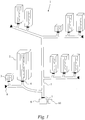
- Fig. 1 is a schematic drawing illustrating an example of a vacuum waste collection system.
- the vacuum waste collection system 1 is installed in a residential and/or business area having a number of buildings.
- Each building 2 is installed with a waste chute 3, or equivalent.
- the waste chutes are vertical chutes extending vertically through the buildings, and each chute normally has several insertion openings with corresponding access ports (not shown).
- Each waste chute is equipped with an openable and closable discharge valve 4, preferably positioned in the basement of the building. When opened the discharge valve 4 establishes communication between the waste chute 3 and an underground transport pipe system 5 for discharging the waste gathered upon the valve into the transport pipe. When closed the discharge valve 4 normally blocks the lower end of the waste chute to provide a seal between the chute and the transport pipe.
- the vacuum waste collection system normally includes a number of transport pipes which form an underground transport pipe system 5 in which waste is transported to a central waste collection point 6 by means of suction of air.
- the central waste collection point may include a central waste collection station and/or a docking point to a mobile waste collection facility.
- the transport pipe system is illustrated as having a main pipe with a number of branches and associated intersections. It should though be understood that the invention is not limited to the particular example of Fig. 1 , and that other configurations of the transport pipe system are feasible as well. For example, there may be several main branches, i.e. branches that are directly connected to the central collection point.
- Each branch in the system has an air inlet valve 8 at the end of the branch.
- the transport pipe system or appropriate parts thereof is exposed to sub-atmospheric pressure or vacuum pressure, and when the air inlet valve 8 of a particular branch is opened the air needed for transporting the waste gathered in the branch transport pipe 5 enters the system and transports the waste to the central collection point 6.
- Sectioning valves may be used to seal different sections of the transport pipe system from each other to ensure sufficient pressure in individual sections for effective suction transport.
- the vacuum waste collection system comprises a control system 10 for controlling emptying and collection/transport of waste in the system.
- the control system 10 is generally configured to control the emptying of waste from the waste chutes into the transport pipe system and the suction transport of waste from different branches of the transport pipe system to the central collection point by controlling the discharge valves, air inlet valves, sectioning valves and main valve of the system according to accepted control technology.
- the invention is not concerned with the specific design of the discharge valves, air inlet valves, sectioning valves and main valves, which are all well known in the art and may be of any conventional type used in vacuum waste collection systems.
- the central waste collection point may include a central waste collection station and/or a docking point to a mobile waste collection unit such as a vacuum truck.
- the central waste collection station may be any conventional station known to the art. Typically, once the waste has been transported to the central station, the waste is compacted at the central station and stored in one or more containers or tanks.
- any conventional mobile collection unit including a conventional vacuum truck may be used.
- the system has a docking point that enables connection to a vacuum truck that may have its own vacuum source onboard to apply primary or secondary vacuum air flow.
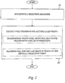
- a basic idea is to successively select a number of branches (S1) in a sequence for emptying and transport of waste, wherein the intersection of each next branch in the sequence is at the same or shorter transport distance to the central waste collection point compared to the intersection of the previous branch in the sequence, and collectively transport (S2) accumulated waste from the selected branches towards the central waste collection point by successively operating the air inlet valves of the corresponding branches.
- the step (S2) of collectively transporting waste involves transporting, for each selected branch except the last branch, accumulated waste towards the central collection point by causing the corresponding air inlet valve to be open until it is detected by detector means in the transport pipe system that the waste has been transported past an intersection to the next branch, and then changing to the next branch.
- the step (S2) of collectively transporting waste involves transporting accumulated waste to the central waste collection point.
- vacuum waste collection system can be operated in a very energy-efficient manner, where a much larger portion of the air flow is seized for transport of waste compared to conventional collection procedures.
- This novel mode of operation makes it possible to reduce the overall collection time and energy consumption. In particular, the period of time when using maximum power of the exhauster can be reduced.
- the risk for blockage in the transport pipe system can be avoided or at least minimized by using detector means in the transport pipe system to ensure, for each branch except the last, that the accumulated waste is transported past the intersection to the next branch.
- the so-called post-suction time is significantly reduced compared to a situation when the waste of each branch is individually transported all the way to central collection point.
- waste in a branch only needs to be transported past the intersection to the next branch, and then the collection procedure can continue with the next branch.
- the step (S1) of successively selecting a number of branches in a sequence involves selecting, if an intersection is associated with two or more branches, a branch having longer physical length or longer so-called equivalent length estimated based on pressure drop in the branch before a branch having shorter physical length or shorter equivalent length.
- the equivalent length is normally estimated based on pressure drop in the branch or pipe, and thus not only considers actual length but also accounts for factors such as the number of bends, valves and other factors.
- the selected branches in the sequence may be all the branches of a main transport pipe within the transport pipe system or a sub-set of the branches of a main transport pipe.
- the sub-set may be e.g. only those branches that have waste chutes with relatively high levels of waste or an otherwise limited set of considered branches.
- the branches are selected according to a so-called " downstream" order, where the intersection of a next branch is normally located at the same transport distance or more downstream compared to the intersection of a previous branch.
- the sequence starts with a branch associated with the intersection having the longest transport distance, or longest equivalent length estimated based on pressure drop, to the central waste collection point.
- the intersection having the longest transport distance or equivalent length to the central waste collection point is associated with two or more branches, the sequence normally starts with the branch having the longest physical length or longest equivalent length estimated based on pressure drop in the branch.
- the sequence may start with the longest branch or the branch having the biggest pressure drop considering not only actual length but accounting also for factors such as the number of bends, valves and other factors that increase the so-called equivalent length.
- the air inlet valves of the branches are successively operated to be open one at a time.
- the procedure of successively operating the air inlet valves includes causing, for at least one branch, an air inlet valve of a previous branch to also be open during a period of time.
- an " additional" air inlet valve of a previous branch may be opened to assist in or take over the transport of accumulated waste during a period of time.
- the step (S1) of successively selecting a number of branches may involve consulting a table-based map of the transport pipe system to find the next branch.
- a table-based map may be defined, e.g. by a table associating each branch with an intersection and indicating, for each intersection, a next intersection being located at the same or shorter transport distance to the central waste collection point.
- the table is configured for indicating, for each branch, the physical length of the branch or the equivalent length estimated based on pressure drop in the branch, and if the identified intersection is associated with two or more branches, a branch having longer physical length or longer so-called equivalent length in the branch is normally selected before a branch having shorter physical length or shorter equivalent length.
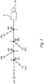
- FIG. 3 is a schematic drawing illustrating an example of a main pipe having a number of branches and being connected to a central waste collection point 6.
- a main transport pipe having a number of branches and associated intersections is illustrated.
- the main transport pipe is connected to the central collection point 6.
- Each branch has a number of waste chutes (indicated by a line perpendicular to the branch pipe), and also has an air inlet valve (AV) at the end of the branch.
- Waste detectors (WD) are arranged in the vicinity of the intersections ( 1 , 2 , 3 , 4 ) to detect waste in the transport pipe system.
- the control system 10 of the vacuum waste collection system is configured for successively selecting a number of branches in a sequence for emptying and transport of waste, wherein the intersection of each next branch in the sequence is at the same or shorter transport distance to the central waste collection point compared to the intersection of the previous branch in the sequence.
- waste may be collectively transported through the transport pipe from the selected branches downstream towards the central waste collection point.
- control system 10 is configured to select, if an intersection is associated with two or more branches, a branch having longer physical length or longer so-called equivalent length estimated based on pressure drop in the branch before a branch having shorter physical length or shorter equivalent length.
- AV5 the sequence starts with the branch of AV5, and then continues with the branch of AV4, the branch of AV3, the branch of AV2 and finally the branch of AV1.
- AV air inlet valve
- this sequence (AV5, AV4, AV3, AV2, AV1) is a so-called reverse or inverse sequence, starting with a branch associated with the intersection having the longest transport distance (or longest equivalent length) to the central waste collection point. It should be understood that it would also be feasible to start the collection sequence with AV4, and continue with AV5, and then AV3, AV2, and AV1.
- the control system 10 is normally configured to start, if the intersection having the longest transport distance or equivalent length to the central waste collection point is associated with two or more branches, the sequence with the branch having the longest physical length or longest equivalent length estimated based on pressure drop in the branch.
- the branch of AV5 is considered to have the longest physical length and/or equivalent length, and therefore the sequence starts with AV5.
- the control system 10 is configured for controlling the transport of waste based on input from the waste detectors WD.
- control system 10 is configured to operate based on input from the waste detectors such that, for each selected branch except the last branch, accumulated waste is transported towards the central waste collection point 6 by controlling the corresponding air inlet valve (AV) to be open until it is detected by one of the waste detectors (WD) that the waste has been transported past an intersection to the next branch, and then changing to the next branch, and such that, for the last branch, accumulated waste is transported to the central waste collection point by controlling the corresponding air inlet valve to be open until the accumulated waste has reached the central waste collection point.
- AV air inlet valve
- the discharge valves of the waste chutes of branch AV5 are opened and waste from the waste chutes are emptied into the branch pipe, and once the last discharge valve in this particular branch is closed, AV5 is opened and the waste is transported by suction of air towards the central waste collection point 6. Once the waste detector arranged in the vicinity of intersection 4 detects that the waste has been transported past intersection 4 , the next branch AV4 is selected.
- the discharge valves of the waste chutes of branch AV4 are opened and waste from the waste chutes are emptied into the branch pipe, and once the last discharge valve in this particular branch is closed, AV4 is opened and the waste is transported by suction of air towards the central collection point 6. Once the waste detector arranged in the vicinity of intersection 3 detects that the accumulated waste (from branch AV5 and branch AV4) has been transported past intersection 3 , the next branch AV3 is selected.
- the discharge valves of the waste chutes of branch AV3 are opened and waste from the waste chutes are emptied into the branch pipe, and once the last discharge valve in this particular branch is closed, AV3 is opened and the waste is transported by suction of air towards the central collection point 6.
- the waste detector arranged in the vicinity of intersection 2 detects that the accumulated waste (from branch AV5, branch AV4 and branch AV3) has been transported past intersection 2 , the next branch AV2 is selected.
- the discharge valves of the waste chutes of branch AV2 are opened and waste from the waste chutes are emptied into the branch pipe, and once the last discharge valve in this particular branch is closed, AV2 is opened and the waste is transported by suction of air towards the central collection point 6.
- the waste detector arranged in the vicinity of intersection 1 detects that the accumulated waste (from branch AV5, branch AV4, branch AV3 and branch AV2) has been transported past intersection 1 , the last branch AV1 is selected.
- the discharge valves of the waste chutes are opened and waste is emptied into the branch pipe, and once the last discharge valve in this particular branch is closed, AV1 is opened and the waste from this branch is transported together with the accumulated waste from (at least some of) branches AV5 to AV2 into the central waste collection point 6. It may be the case that at least some of the accumulated waste from the previous branches has already reached the central collection point.
- control system 10 is configured for determining when to change to a next branch by monitoring the waste detectors in the transport pipe system and performing a controlled change to a next branch when it is detected that waste has been transported past an intersection to a next branch.
- control system 10 is configured to start with a branch associated with the intersection having the longest transport distance (or equivalent length) to the central waste collection point. If several branches are associated to the most " remotely" located intersection, the collection sequence may start with the longest branch or the branch having the biggest pressure drop considering not only actual length but also factors such as the number of bends.
- control system 10 is configured to control the air inlet valves of the different branches to be open one at a time.
- control system 10 may alternatively control, for at least one branch, an air inlet valve of a previous branch to also be open during a period of time.
- the " additional" air inlet valve of a previous branch may be opened to assist in or take over the transport of accumulated waste during a period of time.
- a table-based map of the transport pipe system is built and consulted by the control system 10 to find the next branch.
- a table-based map may be defined, e.g. by a table associating each branch (and corresponding AV) with an intersection and indicating, for each intersection, the next intersection (located at the same or shorter transport distance to the central waste collection point).
- the next intersection is identified in the table-based map and then a next branch associated with the identified intersection can be determined.
- a table-based map of the transport pipe system may be defined by the example below.
- AV Brain
- Associated intersection AV1 1 AV2 2 AV3 3 AV4 4 AV5 4 Intersection Next intersection 1 Collection point 2 1 3 2 4 3
- intersection 4 It is determined that the collection sequence should start with AV4 or AV5 since these branches are associated with the most remotely located intersection 4 .
- AV5 is selected first.
- AV5 is associated with intersection 4 .
- AV4 is also associated with intersection 4 , and is therefore the next AV/branch to process.
- the next intersection is intersection 3 , which is associated with AV3.
- the next intersection is intersection 2 , which is associated with AV2.
- intersection 1 which is associated with AV1.
- the above table-based map is a relatively simple example, and a more detailed example including information about distances and/or equivalent lengths in the transport pipe system will be given later on.
- a sequence of branches/air inlet valves can be determined by consulting the table-based map.
- the use of a table-based map has turned out to be particularly useful in large systems with many branches and intersections, where a table-based map can be helpful in automating the successive selection of branches.
- the operator enters the information about branches/air inlet valves and intersections into the table at set-up of the system control.
- the control system 10 may then consult the table to determine the next branch in the collection sequence.
- Fig. 4 is a schematic diagram illustrating a structural view of a limited part of an exemplary vacuum waste collection system.
- a waste chute 3 is installed in a building in a conventional manner and is equipped with an openable and closable discharge valve 4.
- the discharge valve 4 is preferably positioned in the basement of the building and is used for establishing communication between the waste chute 3 and a branch pipe of an underground transport pipe system 5.
- an air inlet valve 8 is arranged.
- the air inlet valve 8 and the discharge valve 4 are controlled by the control system, which sends appropriate control signals in order to control the opening and closing of the valves.
- Fig. 4 also illustrates an intersection with another branch, and a waste detector 9 arranged in the vicinity of the intersection.
- the waste detector 9 may be any suitable type of detector capable of detecting the presence of waste in the transport pipe including for example ultrasonic, optic, magnetic and radio-type detectors. It is also possible to utilize a so-called color sensor (RX sensor) that is normally used for detecting the color of waste items such as bags and the classified waste type thereof.
- the waste detector 9 is preferably configured for generating signal information representative of the presence of waste. The signal information is preferably sent to the control system for use in controlling the transport of waste towards the central collection point.
- the waste chute 3 may also have an optional level indicator system, for example in the form of a level sensor for measuring or otherwise indicating the level of waste in the waste chute 3.
- the level sensor may be any type of level sensor including ultrasonic, optic, magnetic, radio-type sensors, and color sensors.
- the level sensor is normally positioned in the chute wall or in the vicinity thereof, and configured to generate signal information representative of the level of waste in the waste chute 3. The signal information is preferably sent to the control system for use in controlling the emptying of waste.
- Fig. 5 is a schematic diagram illustrating an example of the detector output level of a waste detector situated in the vicinity of a branch intersection in the transport pipe system.
- a detector output level that is equal to 0 means that no waste or waste is currently detected, whereas a detector output level equal to 1 means that the detector has detected waste or waste in the transport pipe at the intersection.
- the period of time during which the AV is open is referred to as the post suction time.
- the invention proposes to keep the air inlet valve open until it is detected that the waste has been transported past an intersection to a next branch, and then changing to the next branch.
- AV air inlet valve
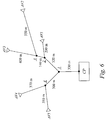
- Fig. 6 is a schematic diagram illustrating a logical view of an example of a vacuum waste collection system.
- An example of a table-based map of the transport pipe system of Fig. 6 can be defined as: Intersection Next intersection Distance to next intersection (m) 1 Collection point 330 2 1 320 3 2 140 4 1 300 AV Associated intersection Distance to associated intersection (m) Equivalent length (m) AV1 2 200 210 AV2 3 550 570 AV3 3 400 415 AV4 4 370 370 AV5 4 350 380
- the table also indicates, for each AV/branch, the physical length of the branch (i.e. the actual distance from the AV to the associated intersection) or equivalent length estimated based on pressure drop in the branch.
- the control system 10 is configured to consult the table-based map to find the next branch. When all branches of a given intersection have been processed, the next intersection is identified in the table-based map and then a next branch associated with the identified intersection can be determined. In this example, if the identified intersection is associated with two or more branches, a branch having longer physical length or longer so-called equivalent length estimated based on pressure drop in the branch is selected before a branch having shorter physical length or shorter equivalent length.
- intersection 3 has the longest transport distance (and/or equivalent length) to the central collection point (CP).
- Two branches (AV2 and AV3) are associated with this intersection.
- AV2 is the longest branch of the two, and therefore it is decided to start the collection procedure with AV2.
- AV2 is kept open until waste from branch AV2 has been transported just past the intersection (intersection 3) to the next branch as detected by waste detector means (not shown in Fig. 6 ).
- AV3 is also associated with intersection 3 , and is therefore the next AV/branch to process.
- AV3 is kept open until waste of branch AV3 and the previously accumulated waste from branch AV2 has been transported just past the intersection (intersection 2 ) to the next branch as detected by waste detector means.
- AV1 is associated with intersection 2, and is the next AV/branch to process.
- AV1 is kept open until waste of branch AV1 and the previously accumulated waste from branches AV2 and AV3 has been transported just past the intersection (intersection 1) to the next branch as detected by waste detector means.
- intersection 1 has a branch to another intersection 4 , which in turn has two further branches with corresponding air inlet valves AV4 and AV5.
- These two branches AV4 and AV5 may be considered independently of the other branches in a separate sequence if desired.
- AV4 is selected first and kept open until waste from this branch has been transported past the intersection (intersection 4 ) to the next branch as detected by waste detector means.
- the air flow will also transport the waste previously accumulated at intersection 1 all the way (or at least closer) to the collection point.
- AV5 is also associated with intersection 4 , which is the next AV/branch to process. Since AV5 is the final AV/branch, AV5 is opened and waste from branch AV5 is transported together with (i.e. in the same air flow) the waste previously accumulated at intersection 4 all the way to the central collection point.
- the overall AV sequence is thus defined as: AV2, AV3, AV1, AV4, AV5.
- AV2, AV3, AV1, AV4, AV5. it should be understood that as an option it may be possible to start with AV3, followed by AV2, since both these branches are connected to the same intersection (i.e. intersection 3 ). This option will anyway allow successive collective transport of waste towards the central collection point.
- both physical length and equivalent length indicate that AV2 should be selected before AV3.
- AV5 may be selected before AV4 since these branches are connected to the same intersection (i.e. intersection 4 ) and the branch of AV5 has a longer equivalent length than the branch of AV4.
- Fig. 7 is a schematic diagram illustrating a logical view of another example of a vacuum waste collection system having a number of main transport pipes.
- Each main pipe is directly connected to the collection point (CP).
- Waste detectors (not shown in Fig. 7 ) are arranged at the branch intersections.
- an example of a collection sequence could be: AV1, AV2; AV3, AV4, AV5; AV6, AV7, AV8, AV9.
- This can be compared to an example of a normal conventional collection sequence: AV2, AV1; AV5, AV4, AV3; AV9, AV8, AV7, AV6.
- Fig. 8 is a schematic diagram illustrating a logical view of yet another example of a vacuum waste collection system.
- a number of branches, AV1 to AV5 have the same intersection.
- the invention may be applicable to provide a more energy-efficient collection procedure. Instead of transporting the waste of a selected branch all the way to the central collection point, which would require a rather long post suction time, the invention proposes to keep the air inlet valve of the selected branch open until it is detected by a waste detector (WD) that the waste has been transported past the common intersection, and then changing to the next branch.
- WD waste detector
- This type of design/solution for a system or system part with many branches having a common intersection may be useful when the waste input flow is relatively small, thus reducing the risk for blockage at the common intersection. It may also be possible to adapt the dimensions of the main transport pipe from the intersection down to the central collection point and/or mechanically design the intersection to facilitate the waste flow and minimize the risk for waste blockage.
- the above actions/steps/procedures for controlling the operation of the vacuum waste collection can for example be performed by a computer, by executing program elements such as functions, procedures or equivalents.
- program elements may be written in a functional programming language, an object oriented programming language or any other suitable programming language and arranged as a computer program for execution by processor hardware.
- Conventional processor technologies including CPU (Central Processing Unit) technologies, DSP (Digital Signal Processor) technologies, ASIC (Application Specific Integrated Circuit) technologies, but also PLC (Programmable Logic Controller) technologies, may be used for implementation.
- the waste collection system is controlled by a computer-implemented control system, which has functions for monitoring and controlling the waste collection system.
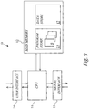
- Fig. 9 is a schematic drawing of an example of a computer-implemented control system.
- the control system 10 basically comprises a computer or processor system in which one or more computer programs are being executed to perform the functions for monitoring and controlling the waste collection system.
- the computer-based control system 10 includes a CPU 11 or equivalent, a main memory 12, a conventional signal interface 13 and a conventional user interface 14.
- the main memory 12 has a program store 15 for computer programs 16 and a data store 17 for data.
- the control system is connected to the other components of the waste collection system through conventional communication links and the control system utilizes the signal interface 13 for receiving signal information from the waste collection system and for sending control signals to discharge valves, air inlet valves, sectioning valves and the main valve of the waste collection system.
- the signal interface 13 is used for receiving information from waste detectors in the transport pipe system, and optionally also from level sensors of the waste chutes.
- This information is then processed by the computer program(s) running on the computer system, and the above-described procedure(s) is thereby executed, resulting in appropriate control signals being sent to the relevant discharge valves, air inlet valves and main valve for effectuating controlled emptying and collection of waste.
- the computer program(s) comprises program means 16 for successively selecting a number of branches in a sequence for emptying waste into the transport pipe system and transporting waste towards the central waste collection point, wherein the intersection of each next branch in the sequence is at the same or shorter transport distance to the central waste collection point compared to the intersection of the previous branch in the sequence.
- the computer program product also comprises program means 16 for determining when to change to a next branch based on input data from detector means in the transport pipe system and performing a controlled change to a next branch when it is detected that waste has been transported past an intersection to a next branch.
- the program means 16 for successively selecting a number of branches in a sequence is configured to select, if an intersection is associated with two or more branches, a branch having longer physical length or longer so-called equivalent length estimated based on pressure drop in the branch before a branch having shorter physical length or shorter equivalent length.
- the computer program is realized as a computer program product, which is normally carried on a computer-readable medium.
- the embodiments described above are to be understood as a few illustrative examples of the present invention. It will be understood by those skilled in the art that various modifications, combinations and changes may be made to the embodiments without departing from the scope of the present invention as defined by the appended claims.
Landscapes
- Engineering & Computer Science (AREA)
- Mechanical Engineering (AREA)
- Physics & Mathematics (AREA)
- Fluid Mechanics (AREA)
- Refuse Collection And Transfer (AREA)
- Air Transport Of Granular Materials (AREA)
Priority Applications (1)
| Application Number | Priority Date | Filing Date | Title |
|---|---|---|---|
| PT107663593T PT2585389T (pt) | 2010-06-23 | 2010-06-23 | Sistema de recolha de resíduos por vácuo e método de funcionamento desse sistema |
Applications Claiming Priority (1)
| Application Number | Priority Date | Filing Date | Title |
|---|---|---|---|
| PCT/SE2010/050715 WO2011162653A1 (en) | 2010-06-23 | 2010-06-23 | Energy-efficient and reliable operation of a vacuum waste collection system |
Publications (2)
| Publication Number | Publication Date |
|---|---|
| EP2585389A1 EP2585389A1 (en) | 2013-05-01 |
| EP2585389B1 true EP2585389B1 (en) | 2017-11-22 |
Family
ID=43646487
Family Applications (1)
| Application Number | Title | Priority Date | Filing Date |
|---|---|---|---|
| EP10766359.3A Active EP2585389B1 (en) | 2010-06-23 | 2010-06-23 | Vacuum waste collection system and method of operating such a system |
Country Status (13)
| Country | Link |
|---|---|
| US (1) | US9073706B2 (OSRAM) |
| EP (1) | EP2585389B1 (OSRAM) |
| KR (2) | KR20130111250A (OSRAM) |
| CN (1) | CN103189285B (OSRAM) |
| AU (1) | AU2010356142B2 (OSRAM) |
| BR (1) | BR112012032940A2 (OSRAM) |
| CA (1) | CA2803507C (OSRAM) |
| DK (1) | DK2585389T3 (OSRAM) |
| ES (1) | ES2657699T3 (OSRAM) |
| NO (1) | NO2585389T3 (OSRAM) |
| PT (1) | PT2585389T (OSRAM) |
| SG (1) | SG186328A1 (OSRAM) |
| WO (1) | WO2011162653A1 (OSRAM) |
Families Citing this family (13)
| Publication number | Priority date | Publication date | Assignee | Title |
|---|---|---|---|---|
| JP2012512794A (ja) | 2008-12-18 | 2012-06-07 | プレミアム パテンツ エスディーエヌ. ビーエイチディー | 固体廃棄物を押し進める方法及びシステム |
| FI122333B (fi) * | 2010-06-03 | 2011-12-15 | Maricap Oy | Menetelmä materiaalinsiirtojärjestelmässä, materiaalinsiirtojärjestelmä ja materiaalinsiirtojärjestelmän alipainelähde |
| EP2433710A1 (en) * | 2010-09-22 | 2012-03-28 | Averda IP B.V. | Apparatus and method for processing bagged refuse |
| FI125741B (fi) * | 2012-07-02 | 2016-01-29 | Maricap Oy | Menetelmä ja laitteisto materiaalin käsittelemiseksi pneumaattisessa materiaalinkäsittelyjärjestelmässä |
| FI124837B (fi) * | 2013-07-30 | 2015-02-13 | Maricap Oy | Menetelmä ja laitteisto jätemateriaalin syöttämiseksi ja käsittelemiseksi |
| FI125194B (fi) * | 2013-07-30 | 2015-06-30 | Maricap Oy | Menetelmä ja laitteisto jätemateriaalin syöttämiseksi ja käsittelemiseksi |
| CN108501970B (zh) * | 2018-04-09 | 2019-08-23 | 武汉理工大学 | 一种真空管道磁悬浮列车污染物排放系统 |
| FI130019B (fi) * | 2018-10-22 | 2022-12-30 | Maricap Oy | Menetelmä materiaalin käsittelemiseksi materiaalinsiirtojärjestelmässä, erotinlaitejärjestely ja materiaalinsiirtojärjestelmä |
| FI20197011A1 (fi) * | 2019-01-25 | 2020-07-26 | Maricap Oy | Menetelmä ja laitteisto materiaalin syöttämiseksi ja siirtämiseksi |
| US11999577B2 (en) | 2019-11-18 | 2024-06-04 | George Archambault | Methods and systems for managing airflow in conduits and pneumatic tubes |
| US11565892B2 (en) * | 2020-07-08 | 2023-01-31 | Trans-Vac Systems LLC | Methods and systems for operation of a vacuum transport system |
| CN112660666B (zh) * | 2020-12-03 | 2024-07-02 | 华晟(青岛)智能装备科技有限公司 | 一种用于污衣被服气力输送系统的分离器 |
| KR20240126267A (ko) | 2023-02-13 | 2024-08-20 | 주식회사 한솔이앤씨 | 침출수 자동 집수 컨테이너 |
Family Cites Families (12)
| Publication number | Priority date | Publication date | Assignee | Title |
|---|---|---|---|---|
| US3788338A (en) * | 1971-06-29 | 1974-01-29 | B Burns | Vacuum sewage conveying with vacuum operated valve |
| DE2637962C3 (de) * | 1976-08-24 | 1980-07-10 | Electrolux Gmbh, 2000 Hamburg | Verfahren zum Abführen der Abwässer von einer Vielzahl von Hausanschlüssen mittels Unterdruck |
| SE515514C2 (sv) * | 1999-02-05 | 2001-08-20 | Centralsug Ab | Metoder för tömning av ett avfallslagringsutrymme respektive ett avfallsinkastschakt samt dylikt avfallsinkastschakt |
| SE514550C2 (sv) | 1999-07-16 | 2001-03-12 | Centralsug Ab | Adaptiv prediktionsbaserad styrning av ett vakuumarbetande avfallsuppsamlingssystem |
| SE514563C2 (sv) * | 1999-07-16 | 2001-03-12 | Centralsug Ab | En metod för avfallsuppsamlingssystem |
| US6565284B2 (en) * | 2000-12-08 | 2003-05-20 | Stephen V. Gearhart | Infiltration control system and method |
| US6698442B1 (en) * | 2002-08-07 | 2004-03-02 | E. Wynn Berry, Jr. | Separated sanitary effluent sewer system |
| AU2003230489A1 (en) | 2003-04-24 | 2004-11-19 | Envac Centralsug Ab | Automated next-hop algorithm for a multi-branch refuse collection system |
| US7249607B2 (en) * | 2004-04-23 | 2007-07-31 | Landfill Service Corporation | Landfill conduit servicing systems and methods for servicing landfill conduits |
| KR101321735B1 (ko) * | 2006-06-09 | 2013-10-29 | 엔박 에이비 | 쓰레기 관리 |
| EP2022731B1 (en) | 2007-08-09 | 2010-01-27 | Ros Roca, S.A. | Method for controlled disposal of refuse |
| FI20085145A7 (fi) * | 2007-12-21 | 2009-06-22 | Maricap Oy | Menetelmä ja laitteisto pneumaattisessa materiaalinsiirtojärjestelmässä |
-
2010
- 2010-06-23 NO NO10766359A patent/NO2585389T3/no unknown
- 2010-06-23 SG SG2012091690A patent/SG186328A1/en unknown
- 2010-06-23 KR KR1020127034203A patent/KR20130111250A/ko not_active Ceased
- 2010-06-23 EP EP10766359.3A patent/EP2585389B1/en active Active
- 2010-06-23 ES ES10766359.3T patent/ES2657699T3/es active Active
- 2010-06-23 PT PT107663593T patent/PT2585389T/pt unknown
- 2010-06-23 AU AU2010356142A patent/AU2010356142B2/en not_active Ceased
- 2010-06-23 CA CA2803507A patent/CA2803507C/en active Active
- 2010-06-23 US US13/805,261 patent/US9073706B2/en active Active
- 2010-06-23 KR KR1020187005044A patent/KR101893783B1/ko active Active
- 2010-06-23 BR BR112012032940A patent/BR112012032940A2/pt not_active Application Discontinuation
- 2010-06-23 DK DK10766359.3T patent/DK2585389T3/en active
- 2010-06-23 WO PCT/SE2010/050715 patent/WO2011162653A1/en not_active Ceased
- 2010-06-23 CN CN201080068682.XA patent/CN103189285B/zh active Active
Also Published As
| Publication number | Publication date |
|---|---|
| WO2011162653A1 (en) | 2011-12-29 |
| AU2010356142B2 (en) | 2014-11-20 |
| PT2585389T (pt) | 2018-01-03 |
| US20130089380A1 (en) | 2013-04-11 |
| BR112012032940A2 (pt) | 2016-11-22 |
| US20130243536A9 (en) | 2013-09-19 |
| AU2010356142A1 (en) | 2013-01-10 |
| EP2585389A1 (en) | 2013-05-01 |
| SG186328A1 (en) | 2013-01-30 |
| KR20180023029A (ko) | 2018-03-06 |
| CA2803507C (en) | 2017-03-14 |
| NO2585389T3 (OSRAM) | 2018-04-21 |
| CN103189285A (zh) | 2013-07-03 |
| KR20130111250A (ko) | 2013-10-10 |
| DK2585389T3 (en) | 2018-02-05 |
| CN103189285B (zh) | 2016-03-30 |
| US9073706B2 (en) | 2015-07-07 |
| KR101893783B1 (ko) | 2018-08-31 |
| HK1181730A1 (zh) | 2013-11-15 |
| CA2803507A1 (en) | 2011-12-29 |
| ES2657699T3 (es) | 2018-03-06 |
Similar Documents
| Publication | Publication Date | Title |
|---|---|---|
| EP2585389B1 (en) | Vacuum waste collection system and method of operating such a system | |
| CN104271471B (zh) | 控制气力输送系统操作的方法 | |
| EP1212246B1 (en) | A system and method for refuse collection | |
| CN102892691B (zh) | 废料排空控制 | |
| CN101778783B (zh) | 垃圾的受控处理方法 | |
| CN1747881B (zh) | 用于多个分支垃圾收集系统的自动化下一步传输算法 | |
| HK1181730B (en) | Vacuum waste collection system and method of operating such a system | |
| HK1203916B (en) | Method of controlling operation of a pneumatic conveying system | |
| HK1174888B (en) | Waste emptying control | |
| HK1086240B (en) | Automated next-hop algorithm for a multi-branch refuse collection system |
Legal Events
| Date | Code | Title | Description |
|---|---|---|---|
| PUAI | Public reference made under article 153(3) epc to a published international application that has entered the european phase |
Free format text: ORIGINAL CODE: 0009012 |
|
| 17P | Request for examination filed |
Effective date: 20130123 |
|
| AK | Designated contracting states |
Kind code of ref document: A1 Designated state(s): AL AT BE BG CH CY CZ DE DK EE ES FI FR GB GR HR HU IE IS IT LI LT LU LV MC MK MT NL NO PL PT RO SE SI SK SM TR |
|
| DAX | Request for extension of the european patent (deleted) | ||
| RAP3 | Party data changed (applicant data changed or rights of an application transferred) |
Owner name: ENVAC AB |
|
| 17Q | First examination report despatched |
Effective date: 20160314 |
|
| GRAP | Despatch of communication of intention to grant a patent |
Free format text: ORIGINAL CODE: EPIDOSNIGR1 |
|
| INTG | Intention to grant announced |
Effective date: 20170630 |
|
| RIN1 | Information on inventor provided before grant (corrected) |
Inventor name: FORESTIER, NIKLAS Inventor name: ARRABAL, DAVID, GONZALEZ |
|
| GRAS | Grant fee paid |
Free format text: ORIGINAL CODE: EPIDOSNIGR3 |
|
| GRAA | (expected) grant |
Free format text: ORIGINAL CODE: 0009210 |
|
| AK | Designated contracting states |
Kind code of ref document: B1 Designated state(s): AL AT BE BG CH CY CZ DE DK EE ES FI FR GB GR HR HU IE IS IT LI LT LU LV MC MK MT NL NO PL PT RO SE SI SK SM TR |
|
| REG | Reference to a national code |
Ref country code: GB Ref legal event code: FG4D |
|
| REG | Reference to a national code |
Ref country code: CH Ref legal event code: EP |
|
| REG | Reference to a national code |
Ref country code: IE Ref legal event code: FG4D |
|
| REG | Reference to a national code |
Ref country code: AT Ref legal event code: REF Ref document number: 948167 Country of ref document: AT Kind code of ref document: T Effective date: 20171215 |
|
| REG | Reference to a national code |
Ref country code: DE Ref legal event code: R096 Ref document number: 602010046909 Country of ref document: DE |
|
| REG | Reference to a national code |
Ref country code: PT Ref legal event code: SC4A Ref document number: 2585389 Country of ref document: PT Date of ref document: 20180103 Kind code of ref document: T Free format text: AVAILABILITY OF NATIONAL TRANSLATION Effective date: 20171221 |
|
| REG | Reference to a national code |
Ref country code: NL Ref legal event code: FP |
|
| REG | Reference to a national code |
Ref country code: DK Ref legal event code: T3 Effective date: 20180202 |
|
| REG | Reference to a national code |
Ref country code: NO Ref legal event code: T2 Effective date: 20171122 |
|
| REG | Reference to a national code |
Ref country code: ES Ref legal event code: FG2A Ref document number: 2657699 Country of ref document: ES Kind code of ref document: T3 Effective date: 20180306 |
|
| REG | Reference to a national code |
Ref country code: SE Ref legal event code: TRGR |
|
| REG | Reference to a national code |
Ref country code: LT Ref legal event code: MG4D |
|
| REG | Reference to a national code |
Ref country code: AT Ref legal event code: MK05 Ref document number: 948167 Country of ref document: AT Kind code of ref document: T Effective date: 20171122 |
|
| PG25 | Lapsed in a contracting state [announced via postgrant information from national office to epo] |
Ref country code: LT Free format text: LAPSE BECAUSE OF FAILURE TO SUBMIT A TRANSLATION OF THE DESCRIPTION OR TO PAY THE FEE WITHIN THE PRESCRIBED TIME-LIMIT Effective date: 20171122 |
|
| PG25 | Lapsed in a contracting state [announced via postgrant information from national office to epo] |
Ref country code: BG Free format text: LAPSE BECAUSE OF FAILURE TO SUBMIT A TRANSLATION OF THE DESCRIPTION OR TO PAY THE FEE WITHIN THE PRESCRIBED TIME-LIMIT Effective date: 20180222 Ref country code: GR Free format text: LAPSE BECAUSE OF FAILURE TO SUBMIT A TRANSLATION OF THE DESCRIPTION OR TO PAY THE FEE WITHIN THE PRESCRIBED TIME-LIMIT Effective date: 20180223 Ref country code: HR Free format text: LAPSE BECAUSE OF FAILURE TO SUBMIT A TRANSLATION OF THE DESCRIPTION OR TO PAY THE FEE WITHIN THE PRESCRIBED TIME-LIMIT Effective date: 20171122 Ref country code: LV Free format text: LAPSE BECAUSE OF FAILURE TO SUBMIT A TRANSLATION OF THE DESCRIPTION OR TO PAY THE FEE WITHIN THE PRESCRIBED TIME-LIMIT Effective date: 20171122 Ref country code: AT Free format text: LAPSE BECAUSE OF FAILURE TO SUBMIT A TRANSLATION OF THE DESCRIPTION OR TO PAY THE FEE WITHIN THE PRESCRIBED TIME-LIMIT Effective date: 20171122 |
|
| REG | Reference to a national code |
Ref country code: FR Ref legal event code: PLFP Year of fee payment: 9 |
|
| PG25 | Lapsed in a contracting state [announced via postgrant information from national office to epo] |
Ref country code: CZ Free format text: LAPSE BECAUSE OF FAILURE TO SUBMIT A TRANSLATION OF THE DESCRIPTION OR TO PAY THE FEE WITHIN THE PRESCRIBED TIME-LIMIT Effective date: 20171122 Ref country code: EE Free format text: LAPSE BECAUSE OF FAILURE TO SUBMIT A TRANSLATION OF THE DESCRIPTION OR TO PAY THE FEE WITHIN THE PRESCRIBED TIME-LIMIT Effective date: 20171122 Ref country code: CY Free format text: LAPSE BECAUSE OF FAILURE TO SUBMIT A TRANSLATION OF THE DESCRIPTION OR TO PAY THE FEE WITHIN THE PRESCRIBED TIME-LIMIT Effective date: 20171122 Ref country code: SK Free format text: LAPSE BECAUSE OF FAILURE TO SUBMIT A TRANSLATION OF THE DESCRIPTION OR TO PAY THE FEE WITHIN THE PRESCRIBED TIME-LIMIT Effective date: 20171122 |
|
| REG | Reference to a national code |
Ref country code: DE Ref legal event code: R097 Ref document number: 602010046909 Country of ref document: DE |
|
| PG25 | Lapsed in a contracting state [announced via postgrant information from national office to epo] |
Ref country code: SM Free format text: LAPSE BECAUSE OF FAILURE TO SUBMIT A TRANSLATION OF THE DESCRIPTION OR TO PAY THE FEE WITHIN THE PRESCRIBED TIME-LIMIT Effective date: 20171122 Ref country code: RO Free format text: LAPSE BECAUSE OF FAILURE TO SUBMIT A TRANSLATION OF THE DESCRIPTION OR TO PAY THE FEE WITHIN THE PRESCRIBED TIME-LIMIT Effective date: 20171122 Ref country code: PL Free format text: LAPSE BECAUSE OF FAILURE TO SUBMIT A TRANSLATION OF THE DESCRIPTION OR TO PAY THE FEE WITHIN THE PRESCRIBED TIME-LIMIT Effective date: 20171122 |
|
| PLBE | No opposition filed within time limit |
Free format text: ORIGINAL CODE: 0009261 |
|
| STAA | Information on the status of an ep patent application or granted ep patent |
Free format text: STATUS: NO OPPOSITION FILED WITHIN TIME LIMIT |
|
| 26N | No opposition filed |
Effective date: 20180823 |
|
| PG25 | Lapsed in a contracting state [announced via postgrant information from national office to epo] |
Ref country code: SI Free format text: LAPSE BECAUSE OF FAILURE TO SUBMIT A TRANSLATION OF THE DESCRIPTION OR TO PAY THE FEE WITHIN THE PRESCRIBED TIME-LIMIT Effective date: 20171122 |
|
| REG | Reference to a national code |
Ref country code: CH Ref legal event code: PL |
|
| REG | Reference to a national code |
Ref country code: BE Ref legal event code: MM Effective date: 20180630 |
|
| REG | Reference to a national code |
Ref country code: IE Ref legal event code: MM4A |
|
| PG25 | Lapsed in a contracting state [announced via postgrant information from national office to epo] |
Ref country code: LU Free format text: LAPSE BECAUSE OF NON-PAYMENT OF DUE FEES Effective date: 20180623 Ref country code: MC Free format text: LAPSE BECAUSE OF FAILURE TO SUBMIT A TRANSLATION OF THE DESCRIPTION OR TO PAY THE FEE WITHIN THE PRESCRIBED TIME-LIMIT Effective date: 20171122 |
|
| PG25 | Lapsed in a contracting state [announced via postgrant information from national office to epo] |
Ref country code: IE Free format text: LAPSE BECAUSE OF NON-PAYMENT OF DUE FEES Effective date: 20180623 Ref country code: LI Free format text: LAPSE BECAUSE OF NON-PAYMENT OF DUE FEES Effective date: 20180630 Ref country code: CH Free format text: LAPSE BECAUSE OF NON-PAYMENT OF DUE FEES Effective date: 20180630 |
|
| PG25 | Lapsed in a contracting state [announced via postgrant information from national office to epo] |
Ref country code: BE Free format text: LAPSE BECAUSE OF NON-PAYMENT OF DUE FEES Effective date: 20180630 |
|
| PG25 | Lapsed in a contracting state [announced via postgrant information from national office to epo] |
Ref country code: MT Free format text: LAPSE BECAUSE OF NON-PAYMENT OF DUE FEES Effective date: 20180623 |
|
| PG25 | Lapsed in a contracting state [announced via postgrant information from national office to epo] |
Ref country code: TR Free format text: LAPSE BECAUSE OF FAILURE TO SUBMIT A TRANSLATION OF THE DESCRIPTION OR TO PAY THE FEE WITHIN THE PRESCRIBED TIME-LIMIT Effective date: 20171122 |
|
| PG25 | Lapsed in a contracting state [announced via postgrant information from national office to epo] |
Ref country code: HU Free format text: LAPSE BECAUSE OF FAILURE TO SUBMIT A TRANSLATION OF THE DESCRIPTION OR TO PAY THE FEE WITHIN THE PRESCRIBED TIME-LIMIT; INVALID AB INITIO Effective date: 20100623 |
|
| PG25 | Lapsed in a contracting state [announced via postgrant information from national office to epo] |
Ref country code: MK Free format text: LAPSE BECAUSE OF NON-PAYMENT OF DUE FEES Effective date: 20171122 |
|
| PG25 | Lapsed in a contracting state [announced via postgrant information from national office to epo] |
Ref country code: AL Free format text: LAPSE BECAUSE OF FAILURE TO SUBMIT A TRANSLATION OF THE DESCRIPTION OR TO PAY THE FEE WITHIN THE PRESCRIBED TIME-LIMIT Effective date: 20171122 Ref country code: IS Free format text: LAPSE BECAUSE OF FAILURE TO SUBMIT A TRANSLATION OF THE DESCRIPTION OR TO PAY THE FEE WITHIN THE PRESCRIBED TIME-LIMIT Effective date: 20180322 |
|
| PGFP | Annual fee paid to national office [announced via postgrant information from national office to epo] |
Ref country code: DE Payment date: 20200416 Year of fee payment: 11 |
|
| PGFP | Annual fee paid to national office [announced via postgrant information from national office to epo] |
Ref country code: IT Payment date: 20210525 Year of fee payment: 12 |
|
| REG | Reference to a national code |
Ref country code: DE Ref legal event code: R119 Ref document number: 602010046909 Country of ref document: DE |
|
| PG25 | Lapsed in a contracting state [announced via postgrant information from national office to epo] |
Ref country code: DE Free format text: LAPSE BECAUSE OF NON-PAYMENT OF DUE FEES Effective date: 20220101 |
|
| PGFP | Annual fee paid to national office [announced via postgrant information from national office to epo] |
Ref country code: NL Payment date: 20220520 Year of fee payment: 13 |
|
| PGFP | Annual fee paid to national office [announced via postgrant information from national office to epo] |
Ref country code: PT Payment date: 20220519 Year of fee payment: 13 |
|
| PG25 | Lapsed in a contracting state [announced via postgrant information from national office to epo] |
Ref country code: IT Free format text: LAPSE BECAUSE OF NON-PAYMENT OF DUE FEES Effective date: 20220623 |
|
| PG25 | Lapsed in a contracting state [announced via postgrant information from national office to epo] |
Ref country code: PT Free format text: LAPSE BECAUSE OF NON-PAYMENT OF DUE FEES Effective date: 20231226 |
|
| REG | Reference to a national code |
Ref country code: NL Ref legal event code: MM Effective date: 20230701 |
|
| PG25 | Lapsed in a contracting state [announced via postgrant information from national office to epo] |
Ref country code: NL Free format text: LAPSE BECAUSE OF NON-PAYMENT OF DUE FEES Effective date: 20230701 |
|
| PGFP | Annual fee paid to national office [announced via postgrant information from national office to epo] |
Ref country code: GB Payment date: 20240516 Year of fee payment: 15 |
|
| PGFP | Annual fee paid to national office [announced via postgrant information from national office to epo] |
Ref country code: DK Payment date: 20240516 Year of fee payment: 15 |
|
| PGFP | Annual fee paid to national office [announced via postgrant information from national office to epo] |
Ref country code: NO Payment date: 20240521 Year of fee payment: 15 Ref country code: FR Payment date: 20240516 Year of fee payment: 15 Ref country code: FI Payment date: 20240516 Year of fee payment: 15 |
|
| PGFP | Annual fee paid to national office [announced via postgrant information from national office to epo] |
Ref country code: ES Payment date: 20250801 Year of fee payment: 16 |
|
| PGFP | Annual fee paid to national office [announced via postgrant information from national office to epo] |
Ref country code: SE Payment date: 20250731 Year of fee payment: 16 |