EP2584283A1 - Verfahren und Vorrichtung zur Hangsicherung mit zusätzlicher Anordnung von Photovoltaikelementen zur Energiegewinnung - Google Patents
Verfahren und Vorrichtung zur Hangsicherung mit zusätzlicher Anordnung von Photovoltaikelementen zur Energiegewinnung Download PDFInfo
- Publication number
- EP2584283A1 EP2584283A1 EP11190770.5A EP11190770A EP2584283A1 EP 2584283 A1 EP2584283 A1 EP 2584283A1 EP 11190770 A EP11190770 A EP 11190770A EP 2584283 A1 EP2584283 A1 EP 2584283A1
- Authority
- EP
- European Patent Office
- Prior art keywords
- photovoltaic module
- ball
- sleeve
- adapter
- slope
- Prior art date
- Legal status (The legal status is an assumption and is not a legal conclusion. Google has not performed a legal analysis and makes no representation as to the accuracy of the status listed.)
- Granted
Links
- 238000000034 method Methods 0.000 title claims abstract description 12
- 230000006641 stabilisation Effects 0.000 title claims description 6
- 239000002689 soil Substances 0.000 claims description 6
- 238000011105 stabilization Methods 0.000 claims description 5
- 238000005553 drilling Methods 0.000 claims description 3
- 238000004519 manufacturing process Methods 0.000 claims description 2
- 239000004568 cement Substances 0.000 claims 2
- 230000003014 reinforcing effect Effects 0.000 abstract 1
- 238000002347 injection Methods 0.000 description 5
- 239000007924 injection Substances 0.000 description 5
- 238000010276 construction Methods 0.000 description 3
- 238000004873 anchoring Methods 0.000 description 2
- 239000004746 geotextile Substances 0.000 description 2
- 239000004570 mortar (masonry) Substances 0.000 description 2
- 239000000243 solution Substances 0.000 description 2
- 235000017060 Arachis glabrata Nutrition 0.000 description 1
- 241001553178 Arachis glabrata Species 0.000 description 1
- 235000010777 Arachis hypogaea Nutrition 0.000 description 1
- 235000018262 Arachis monticola Nutrition 0.000 description 1
- RRLHMJHRFMHVNM-BQVXCWBNSA-N [(2s,3r,6r)-6-[5-[5-hydroxy-3-(4-hydroxyphenyl)-4-oxochromen-7-yl]oxypentoxy]-2-methyl-3,6-dihydro-2h-pyran-3-yl] acetate Chemical compound C1=C[C@@H](OC(C)=O)[C@H](C)O[C@H]1OCCCCCOC1=CC(O)=C2C(=O)C(C=3C=CC(O)=CC=3)=COC2=C1 RRLHMJHRFMHVNM-BQVXCWBNSA-N 0.000 description 1
- 239000011083 cement mortar Substances 0.000 description 1
- 238000009826 distribution Methods 0.000 description 1
- 238000003306 harvesting Methods 0.000 description 1
- 235000020232 peanut Nutrition 0.000 description 1
- 238000010248 power generation Methods 0.000 description 1
- 239000002243 precursor Substances 0.000 description 1
- 238000003825 pressing Methods 0.000 description 1
- 238000011084 recovery Methods 0.000 description 1
- 230000002787 reinforcement Effects 0.000 description 1
- 239000011378 shotcrete Substances 0.000 description 1
Images

Classifications
-
- F—MECHANICAL ENGINEERING; LIGHTING; HEATING; WEAPONS; BLASTING
- F24—HEATING; RANGES; VENTILATING
- F24S—SOLAR HEAT COLLECTORS; SOLAR HEAT SYSTEMS
- F24S25/00—Arrangement of stationary mountings or supports for solar heat collector modules
- F24S25/60—Fixation means, e.g. fasteners, specially adapted for supporting solar heat collector modules
- F24S25/61—Fixation means, e.g. fasteners, specially adapted for supporting solar heat collector modules for fixing to the ground or to building structures
- F24S25/617—Elements driven into the ground, e.g. anchor-piles; Foundations for supporting elements; Connectors for connecting supporting structures to the ground or to flat horizontal surfaces
-
- F—MECHANICAL ENGINEERING; LIGHTING; HEATING; WEAPONS; BLASTING
- F24—HEATING; RANGES; VENTILATING
- F24S—SOLAR HEAT COLLECTORS; SOLAR HEAT SYSTEMS
- F24S30/00—Arrangements for moving or orienting solar heat collector modules
- F24S30/40—Arrangements for moving or orienting solar heat collector modules for rotary movement
- F24S30/48—Arrangements for moving or orienting solar heat collector modules for rotary movement with three or more rotation axes or with multiple degrees of freedom
-
- Y—GENERAL TAGGING OF NEW TECHNOLOGICAL DEVELOPMENTS; GENERAL TAGGING OF CROSS-SECTIONAL TECHNOLOGIES SPANNING OVER SEVERAL SECTIONS OF THE IPC; TECHNICAL SUBJECTS COVERED BY FORMER USPC CROSS-REFERENCE ART COLLECTIONS [XRACs] AND DIGESTS
- Y02—TECHNOLOGIES OR APPLICATIONS FOR MITIGATION OR ADAPTATION AGAINST CLIMATE CHANGE
- Y02E—REDUCTION OF GREENHOUSE GAS [GHG] EMISSIONS, RELATED TO ENERGY GENERATION, TRANSMISSION OR DISTRIBUTION
- Y02E10/00—Energy generation through renewable energy sources
- Y02E10/40—Solar thermal energy, e.g. solar towers
- Y02E10/47—Mountings or tracking
Definitions
- the invention relates to a method and a device for slope protection with additional arrangement of photovoltaic elements for energy.
- ground anchor used which are often designed as injection anchors
- the length of the injection anchor used can be up to 30 m.
- cement mortar can already be pumped into the cavity of the rotating armature, whereby an injection of the hollow rod takes place analogously to the pipe precursor.
- the task is to combine a well-known slope protection or embankment attachment measure with an additional function of energy production and thus make the creation of large-scale slope fortifications by an economic use of these hillside areas more attractive.
- the method described for the attachment and simultaneous establishment of an energy recovery device should be carried out with little additional effort.
- ground anchors in the construction of solar collectors and their support devices for secure anchoring in the ground.
- German Utility Model Publication DE 20 2008 003 830 U1 Such a support means for solar collectors in which a plurality of ground anchors is used for attachment of the support means.
- the background to this is, among other things, the planar orientation of the solar collectors, which in particular represent a large area of attack for wind forces. For this reason, it is not sufficient to set up these support structures only on the ground, since the weight is insufficient to secure against the wind forces.
- Another publication is, for example, a modular support system for solar collectors in the publication DE 20 2006 019 031 U1 , where also a plurality of solar collectors are arranged on a carrying system and a plurality of ground anchors secures this construction on the ground.
- the Utility Model DE 20 2010 003 834 also discloses a free-field solar system on a stud structure, which stud structure is fixed in the ground via an anchoring body.
- the inventive method for slope stabilization and additional arrangement of photovoltaic modules provides Erdnägel for slope protection as described in the description to bring into the slope to be secured, to fix them via suitable security measures, for example, injection of mortar in the ground, in an next step, an adapter element on the free end of Erdnagels set up close to the ground, which receives a connecting body for receiving a solar module or even as an integral part of such a connecting element.
- the free ends of the pegs thus used as abutments are not to be seen here as holding masts in the sense of the prior art, but arranged as just outstanding from the embankment Erdnagelenden ending slightly above the ground.
- the alignment of the free ends of the pegs is not vertical as usual in the prior art but tend to be horizontal to inclined, with an alignment is approximately perpendicular to the slope of the slope as a rule.
- the inventive method therefore provides that a special connection of the connecting elements of adapter and connecting member and the solar module or the solar module supporting frame is provided.
- the inventive device for slope protection and simultaneous support of a solar module according to the invention consists of the peg, which should not primarily in its configuration to carry the solar module but primarily to secure the slope. It is therefore a peg that is significantly larger than the size would be required for a secure recording of a solar module.
- the adapter element at the free end of the peg can in this case only comprise an adapter sleeve, which in turn serves as a connecting element to a holding device for a frame system of a solar element.
- an adapter sleeve which at the same time also has connecting elements to the solar module or to the frame system of the solar module.
- This adapter sleeve provides that this can be placed by means of an internal thread on the external thread of the free end of the peg.
- This free peanut end enclosing adapter sleeve is in this design in a ball sleeve in which a ball is mounted in a fixed, which has a connection extension to the solar module and the frame system of the solar module.
- a suitable design in this case provides for a fixing punch, which is arranged on the inside in the adapter sleeve and allows a determination of the ball element in the ball sleeve for alignment of the holding extension on the ball element. In this way, the ball element can be fixed in a desired direction of inclination of the holding extension in the ball sleeve of the adapter sleeve.
- a spinous process is arranged on the ball element in the ball sleeve, which can engage in a corresponding receptacle on the solar element or on the frame system of the solar element.
- a spinous process is arranged on the ball element in the ball sleeve, which can engage in a corresponding receptacle on the solar element or on the frame system of the solar element.
- an approximately x-shaped holding frame element for receiving a solar module is provided that at the intersection of the x-arms a bore having as Dornaufillon for the retaining mandrel on the mounting ball.
- FIGS. 1 and 2 represent the adapter element for arranging a photovoltaic module at the free end of a ground anchor
- FIGS. 1 and 2 is this adapter in the form of a ball joint connection in two cut perspectives represents, namely in a 90 degree turned view.
- the figures show here the peg 1 or the free Erdnagelende, which serves as a point of attack for the ball joint connection protruding from the ground.
- a lock nut 2 which serves as a contact surface for the adapter sleeve 3 and thus limits their unscrewing depth on the ground anchor.
- the connection between the lock nut 2, adapter sleeve 3 and peg 1 is given here by internal thread in lock nut and adapter sleeve and the round thread 11 on the outer surface of the peg 1.
- the peg is designed as a hollow body, whereby it can receive the holding attachment 4 of a fixing ram 5, which is arranged in the adapter sleeve and has a rounded connection surface adapted to the radius of the connection ball 6 in the illustrated design.
- a mandrel 9 which is arranged out of the ball sleeve 8 outstanding rod-shaped.
- the alignment of this mandrel thus serves the alignment of the photovoltaic module itself, which is why this alignment of the mandrel on the previously described attachment of the ball by screwing the ball sleeve is reached.
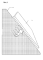
- FIG. 5 now shows schematically the arrangement of the photovoltaic module on the peg with intermediate adapter sleeve or ball joint connection. It can be seen here that the arrangement of the peg takes place in a steep slope, which is why special pegs are used in the form described here.
- the lock nut On the free Erdnagelende, which protrudes only slightly from the slope or from the slope is the lock nut, which serves as a bearing surface for the adapter sleeve, which in turn carries the corresponding ball sleeve with ball and connecting mandrel.
- the connecting mandrel now engages in the back of the photovoltaic module or in the frame system for receiving the photovoltaic module.
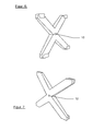
- FIGS. 6 and 7 Finally, from the front and rear view, a possible design of a frame system for receiving a photovoltaic module, as this would be well combined with the present ball joint connection.
- an x-shaped design of the frame system is provided so that the photovoltaic module is securely held between these x-shaped arms. It is thus a lightweight design that can be easily arranged on the central retaining mandrel.
- a mandrel receiver 10 is arranged, which is formed in the present design as a continuous bore through the x-shaped frame. It is thus possible to set in a first step, the adapter on the free end of the peg, align the mandrel according to the slope and the desired inclination of the photovoltaic module and now set up in the next step, the x-shaped frame on the retaining pin and here by means of appropriate Lock fasteners.
Landscapes
- Engineering & Computer Science (AREA)
- Physics & Mathematics (AREA)
- Life Sciences & Earth Sciences (AREA)
- Sustainable Development (AREA)
- Sustainable Energy (AREA)
- Thermal Sciences (AREA)
- Chemical & Material Sciences (AREA)
- Combustion & Propulsion (AREA)
- Mechanical Engineering (AREA)
- General Engineering & Computer Science (AREA)
- Piles And Underground Anchors (AREA)
- Photovoltaic Devices (AREA)
Abstract
Description
- Die Erfindung betrifft ein Verfahren sowie eine Vorrichtung zur Hangsicherung mit zusätzlicher Anordnung von Photovoltaikelementen zur Energiegewinnung.
- Es ist aus dem Stand der Technik bekannt, zur Hangsicherung oder Böschungssicherung im Bereich beispielsweise des Strassenbaus oder der Bahntrassen Hohlstabanker als Bodennägel zu verwenden beispielsweise im Zusammenwirken mit Geotextilien. Diese Befestigungen empfehlen sich insbesondere bei losen oder instablien Böden, wie diese beispielsweise bei Böschungs-Auffüllungen oder lockerem, aufgeworfenem Abraum vorliegen. Die Bodenvernagelung erfolgt hierbei in der Regel mit einem rhombenförmigen Raster, um eine effiziente Verteilung der Bewehrung zu erreichen.
- Das Einbringen der verwendeten Erdanker, die häufig als Injektionsanker ausgebildet sind, erfolgt in der Regel durch Bohrsysteme, die beispielsweise auf Raupenfahrwerken aufmontiert sind. Die Länge der verwendeten Injektionsanker kann hierbei bis zu 30 m betragen. Während des Bohrvorgangs kann hierbei bereits Zementmörtel in den Hohlraum des rotierenden Ankers eingepumpt werden, wodurch analog zum Rohrvorschnitt eine Injektion des Hohlstabes erfolgt.
- Als Abschluss nach Einbringung des Erdnagels wird häufig zur Stabilisierung der verwendeten beispielsweise Geotextilmatten oder Baustahlgewebe eine Ankerplatte auf dem aus dem Erdreich ragenden freien Ende des Erdnagels befestigt. Das freie Ende verbleibt hierbei herausragend aus der nun befestigten geneigten Böschung bzw. Hangfläche.
- Auf derartige Weise kommt es zur Absicherung und Befestigung von Böschungen und Hangflächen, die in der Regel großflächig angelegt und beispielsweise mit Spritzbeton oder auch mit Begrünungen zusätzlich stabilisiert werden können. Allerdings ist es hierbei nachteilig, dass diese großen stabilisierten Flächen keinerlei Nutzungsmöglichkeit erlauben und somit lediglich in ihrer Funktion als Befestigung oder auch als Lärmschutz dauerhaft angelegt werden.
- Hier setzt die Aufgabenstellung der vorliegenden Erfindung an. Die Aufgabenstellung ist es, eine bekannte Hangsicherung bzw. Böschungsbefestigungsmaßnahme mit einer zusätzlichen Funktion der Energiegewinnung zu kombinieren und somit das Anlegen großflächiger Hangbefestigungen durch eine wirtschaftliche Nutzung dieser Hangflächen attraktiver zu machen. Das beschriebene Verfahren zur Befestigung und gleichzeitiger Errichtung einer Energiegewinnungsvorrichtung soll hierbei bei geringem zusätzlichem Aufwand erfolgen.
- Gleichzeitig soll dies eine Ausrichtung der Energiegewinnungsmodule auf den verwendeten Erdnägeln ermöglichen. Dies ist auch Aufgabe der entsprechenden Vorrichtung zur Befestigung eines Energiegewinnungsmoduls auf einem freien Ende eines Erdnagels, wobei hier auch die sichere und leichte Befestigung des Energiemoduls auf dem freien Ende des Erdnagels erreicht werden soll.
- Aus dem Stand der Technik ist in diversen Publikationen bekannt, beim Aufbau von Solarkollektoren und deren Trageeinrichtungen zur sicheren Verankerung im Erdboden Erdanker zu verwenden. So offenbart beispielsweise die deutsche Gebrauchsmusterschrift
DE 20 2008 003 830 U1 eine derartige Trageeinrichtung für Solarkollektoren bei der eine Vielzahl von Erdankern zur Befestigung der Trageeinrichtung verwendet wird. - Hintergrund hierfür ist unter anderem die flächige Ausrichtung der Solarkollektoren, die insbesondere eine große Angriffsfläche für Windkräfte darstellen. Aus diesem Grund ist es nicht ausreichend, diese Tragekonstruktionen lediglich auf den Erdboden aufzustellen, da das Eigengewicht zur Sicherung gegen die Windkräfte nicht ausreicht.
- Eine andere Veröffentlichung ist beispielsweise ein modulares Tragesystem für Solarkollektoren in der Veröffentlichung
DE 20 2006 019 031 U1 , wo auch eine Vielzahl von Solarkollektoren auf einem Tragesystem angeordnet sind und eine Vielzahl von Erdankern diese Konstruktion auf dem Boden sichert. - Die Gebrauchsmusterschrift
DE 20 2010 003 834 offenbart ebenfalls ein Freilandsolarsystem auf einer Ständerkonstruktion, wobei diese Ständerkonstruktion über einen Verankerungskörper im Erdreich befestigt ist. - Schließlich ist in der
EP 2320156 A2 ein Haltemast offenbart, der als Erdanker in den Boden eingeschraubt wird. Es wird hierbei ein schraubenförmiger Anker vorgeschlagen, wobei dessen Einschraubtiefe in etwa das Doppelte der Länge betragen soll, die dieser Haltemast aus dem Erdreich herausragend angeordnet ist. - Auch dies ist lediglich eine Vorrichtung, die die sichere Befestigung eines Solarmoduls auf dem Erdboden sichern soll, allerdings in keiner Weise eine Sicherung des Erdboden selbst gegen Erdbewegungen bewirkt. Insbesondere handelt es sich bei allen in Stand der Technik aufgezeigten Lösungen um Anordnungen, die eine Anordnung der Tragekonstruktionen auf ebener Erde vorsehen und keine Lösungen für eine Anordnung auf Böschungen.
- Das erfindungsgemäße Verfahren zur Hangsicherung und zusätzlichen Anordnung von Photovoltaikmodulen sieht vor, Erdnägel zur Hangsicherung wie in der Beschreibung erläutert in den zu sichernden Hangbereich einzubringen, diese über geeignete Sicherungsmaßnahmen, beispielsweise Injizierung von Mörtel im Erdreich zu fixieren, in einem nächsten Schritt ein Adapterelement auf das freie Ende des Erdnagels bodennah aufzusetzen, welches einen Verbindungskörper zur Aufnahme eines Solarmoduls aufnimmt bzw. selbst als integralen Bestandteil ein derartiges Verbindungselement aufweist.
- Die so als Widerlager verwendeten freien Enden der Erdnägel sind hierbei nicht als Haltemasten in Sinne der Standes der Technik zu sehen, sondern als lediglich aus der Böschung herausragende Erdnagelenden geringfügig über dem Erdboden endend angeordnet. Die Ausrichtung der freien Enden der Erdnägel wird hierbei nicht wie im Stand der Technik üblich vertikal sondern tendenziell horizontal bis geneigt erfolgen, wobei eine Ausrichtung in etwa lotrecht auf der Neigung des Hanges als Regelfall vorliegt.
- Das erfindungsgemäße Verfahren sieht daher vor, dass eine spezielle Verbindung der Verbindungselemente von Adapter und Verbindungsglied sowie des Solarmoduls bzw. des das Solarmoduls tragenden Rahmens vorgesehen ist.
- Die erfindungsgemäße Vorrichtung zur Hangsicherung und gleichzeitigen Halterung eines Solarmoduls besteht erfindungsgemäß aus dem Erdnagel, der in seiner Konfiguration nicht primär das Tragen des Solarmoduls sondern primär die Sicherung des Hanges bewirken soll. Es handelt sich hierbei demnach um einen Erdnagel, der deutlich grösser dimensioniert ist als die für eine sichere Aufnahme eines Solarmoduls erforderlich wäre. Zudem ist es zweckmäßig, einen Erdnagel mit Injektion eines Mörtels zu verwenden, um so eine optimale Hangsicherung zu erreichen.
- Das Adapterelement am freien Ende des Erdnagels kann hierbei lediglich eine Adapterhülse umfassen, die wiederum als Verbindungselement zu einer Haltevorrichtung für ein Rahmensystem eines Solarelementes dient. Es ist allerdings zweckmäßig, eine Adapterhülse zu schaffen, die gleichzeitig auch Verbindungselemente zum Solarmodul bzw. zum Rahmensystem des Solarmoduls aufweist.
- Eine vorteilhafte Ausbildung dieser Adapterhülse sieht dabei vor, dass diese mittels eines Innengewindes auf das Außengewinde des freien Endes des Erdnagels aufgesetzt werden kann. Diese das freie Erdnagelende umschließende Adapterhülse geht in dieser Bauform in eine Kugelhülse über, in der eine Kugel fixierbar gelagert ist, die über einen Verbindungsfortsatz zum Solarmodul bzw. zum Rahmensystem des Solarmoduls verfügt.
- Eine zweckmäßige Bauform sieht hierbei einen Fixierungsstempel vor, der innenseitig in der Adapterhülse angeordnet ist und eine Feststellung des Kugelelements in der Kugelhülse zur Ausrichtung des Haltefortsatzes am Kugelelement ermöglicht. Auf diese Weise kann das Kugelelement in einer gewünschten Neigungsrichtung des Haltefortsatzes in der Kugelhülse der Adapterhülse fixiert werden.
- In einer zweckmäßigen Ausgestaltung der Adapterhülse ist an dem Kugelelement in der Kugelhülse ein Dornfortsatz angeordnet, der in eine entsprechende Aufnahme am Solarelement bzw. an Rahmensystem des Solarelementes eingreifen kann. Hierfür ist beispielsweise bei einer zweckmäßigen Bauform ein in etwa x-förmiges Halterahmenelement zur Aufnahme eines Solarmoduls vorgesehen, dass im Schnittpunkt der x-Arme eine Bohrung als Dornaufnehmer für den Haltedorn an der Befestigungskugel aufweist.
- Nachfolgend sei eine Ausführungsform der Erfindung anhand von Zeichnungen näher erläutert.
- Es zeigen
- Figur 1
- den erfindungsgemäßen Halteadapter zur Anordnung eines Photovoltaik-Moduls in geschnittener Darstellung,
- Figur 2
- den Adapter zur Aufnahme des PV-Moduls mit um 90 Grad gedrehter Kugelhülse im Schnitt,
- Figur 3
- eine Frontalansicht des Kugelgelenkanschlusses in Position 0 Grad,
- Figur 4
- eine Frontalansicht des Kugelgelenkanschlusses in Position 90 Grad,
- Figur 5
- eine perspektivische Gesamtansicht der Anordnung des Photovoltaikmoduls auf einem Erdnagel mit Verwendung der Adapterhülse,
- Figur 6
- eine perspektivische Frontalansicht des x-förmigen Halterahmens des Photovoltaikmoduls und
- Figur 7
- eine perspektivische Rückansicht des Halterahmens des Photovoltaikmoduls.
- Die
Figuren 1 - 4 stellen das Adapterelement zur Anordnung eines Photovoltaikmoduls am freien Ende eines Erdankers dar. InFigur 1 und 2 ist dieser Adapter in der Bauform als Kugelgelenkanschluss in zwei geschnittenen Perspektiven darstellt, nämlich in einer um 90 Grad gewendeten Ansicht. Die Figuren zeigen hierbei den Erdnagel 1 bzw. das freie Erdnagelende, welches aus dem Erdreich herausragende als Angriffspunkt für den Kugelgelenkanschluss dient. - Auf diesen Erdnagel 1 aufgesetzt ist als erstes Bauelement eine Kontermutter 2, die als Anlagefläche für die Adapterhülse 3 dient und somit deren Aufschraubtiefe auf den Erdanker beschränkt. Die Verbindung zwischen Kontermutter 2, Adapterhülse 3 und Erdnagel 1 ist hierbei über Innengewinde in Kontermutter und Adapterhülse sowie dem Rundgewinde 11 am Außenmantel des Erdnagels 1 gegeben.
- Es ist hierbei erkennbar, dass der Erdnagel als Hohlkörper ausgebildet ist, wodurch dieser den Haltevorsatz 4 eines Befestigungsstempels 5 aufnehmen kann, der in der Adapterhülse angeordnet ist und in der dargestellten Bauform eine gerundete Verbindungsfläche angepasst am Radius der Verbindungskugel 6 zu dieser aufweist.
- Mittels eines Feingewindes 7 ist auf der Adapterhülse vorderseitig eine weitere Hülse aufgeschraubt, nämlich die Kugelhülse 8, die eine Verbindungskugel 6 an der Adapterhülse fixiert. Diese Verbindungskugel liegt somit mit Ihrer Außenfläche an dem Stempel 5 an und wird durch das Aufschrauben der Kugelhülse an diesen Stempel 5 angedrückt, wodurch die Kugel 6 in der Adapterhülse 3 durch die Kugelhülse 8 fixiert werden kann. Das heißt, bei nicht ganz aufgeschraubter Kugelhülse 8 auf der Adapterhülse 3 ist die Kugel 6 in der Kugelhülse 8 noch frei beweglich, wird dann aber die Kugelhülse 8 weiter auf die Adapterhülse 3 aufgeschraubt, kommt es zu einem Andrücken der Kugelhülse 8 und somit zu einer kraftschlüssigen Befestigung der Kugel 6 in ihrer Position in der Kugelhülse 8.
- Hierfür ist die Zusammenschau der
Figuren 1 und 2 hilfreich, da erkennbar ist, dass die Kugelhülse 8 eine außenflächige seitliche Abflachung 12 aufweist, wie diese auch in denFiguren 3 und 4 in der Frontansicht erkennbar ist. Dies dient dem Angriff eines Werkzeugs zum Aufdrehen der Kugelhülse 8 auf die Adapterhülse 3 und somit zur Fixierung der Kugel 6 in der Kugelhülse 8. - Von der Kugel 6 ausgehend und mit dieser verbunden ist ein Dorn 9, der aus der Kugelhülse 8 herausragend stabförmig angeordnet ist. Dieser in etwa stabförmige Dorn dient als Verbindungskörper zum Photovoltaikmodul 13 bzw. zum Rahmensystem zur Aufnahme des Photovoltaikmoduls 13. Die Ausrichtung dieses Dorns dient somit der Ausrichtung des Photovoltaikmoduls selbst, weshalb diese Ausrichtung des Dorns über die zuvor beschriebene Befestigung der Kugel durch ein Anschrauben der Kugelhülse erreicht wird.
-
Figur 5 zeigt nun schematisch die Anordnung des Photovoltaikmoduls auf dem Erdnagel mit zwischengeschalteter Adapterhülse bzw. Kugelgelenkanschluss. Es ist hierbei erkennbar, dass die Anordnung des Erdnagels in einer steilen Hanglage erfolgt, weshalb hier spezielle Erdnägel in der beschriebenen Form verwendet werden. Auf dem freien Erdnagelende, welches nur geringfügig aus der Böschung bzw. aus dem hang herausragt ist die Kontermutter, die als Anlagefläche für die Adapterhülse dient, die wiederum die entsprechende Kugelhülse mit Kugel und Verbindungsdorn trägt. Der Verbindungsdorn greift nun rückseitig in das Photovoltaikmodul ein bzw. in das Rahmensystem zur Aufnahme des Photovoltaikmoduls. - Die
Figuren 6 und 7 schließlich zeigen aus Front- und Rückansicht eine mögliche Bauform eines Rahmensystems zur Aufnahme eines Photovoltaikmoduls, wie dieses mit der vorliegenden Kugelgelenkverbindung gut kombinierbar wäre. Es ist hierbei eine x-förmige Ausbildung des Rahmensystems vorgesehen, so dass das Photovoltaikmodul zwischen diesen x-förmigen Armen sicher gehalten wird. Es handelt sich somit um eine leichte Bauform, die ohne weiteres auf dem zentralen Haltedorn angeordnet werden kann. - In der Schnittachse der x-förmigen Arme ist ein Dornaufnehmer 10 angeordnet, der in der vorliegenden Bauform als durchgängige Bohrung durch den x-förmigen Rahmen ausgebildet ist. Es ist somit möglich, in einem ersten Schritt den Adapter auf das freie Ende des Erdnagels zu setzten, den Dorn entsprechend der Hangneigung und der gewünschten Neigung des Photovoltaikmoduls auszurichten und nun im nächsten Schritt den x-förmigen Rahmen auf den Haltedorn aufzusetzen und hier mittels geeigneter Befestigungsmittel zu arretieren.
Claims (10)
- Verfahren zur Hangsicherung mit zusätzlicher Anordnung von Photovoltaikelementen zur Energiegewinnung,
umfassend die Verfahrensschrittea) Einbringung einer Vielzahl von Erdnägeln in den zu sichernden Hangbereich,b) Aufsetzen einer Adapterhülse auf das geringfügig aus dem Hang herausragende freie Ende des eingebrachten Erdnagels,c) Ausrichten eines Verbindungskörpers an der Adapterhülse zum Photovoltaikmodul,d) Aufsetzen und Arretieren des Photovoltaikmoduls auf den Erdnagel. - Verfahren zur Hangsicherung mit zusätzlicher Anordnung von Photovoltaikelementen nach Anspruch 1,
dadurch gekennzeichnet, dass
als Erdanker ein selbstbohrendes Drill-Hohlstab-Ankersystem mit durchgehendem Außengewinde verwendet wird, welches ohne Verrohrung in das Erdreich eingebracht wird. - Verfahren zur Hangsicherung mit zusätzlicher Anordnung von Photovoltaikelementen nach Anspruch 1 oder 2,
dadurch gekennzeichnet, dass
während des Einbringens des Hohlstab-Ankersystems direkt Zementmörtel in das Ankersystem injiziert wird, welcher sich gleichmäßig im Rohrloch verteilt und somit eine hohe Verbunfestigkeit zwischen Hohlstabanker und den Bodenschichten bewirkt. - Vorrichtung zur Hangsicherung sowie zur Aufnahme von Photovoltaikmodulen,
dadurch gekennzeichnet, dass- die Vorrichtung aus einem Erdankersystem gebildet wird, welches zur Hangsicherung in das Erdreich eingebracht wird,- aus einem Adapterelement, welches auf das freie aus dem Erdreich ragende Ende des Ankersystems abschließend aufgeschraubt wird- sowie aus Verbindungsmitteln an dem Adapterkörper zu einem Photovoltaikmodul oder zu einem Halterahmen für ein Photovoltaikmodul. - Vorrichtung zur Hangsicherung nach Anspruch 4,
dadurch gekennzeichnet, dass
die Adapterhülse (3) mittels eines Innengewindes auf das Außengewinde des Erdnagels 1 aufgeschraubt wird. - Vorrichtung zur Hangsicherung nach Anspruch 4 oder 5.
dadurch gekennzeichnet, dass
die Adapterhülse eine Kugelgelenkverbindung zum Photovoltaikmodul aufweist, die mittels einer Kugelhülse (6) an der Adapterhülse (3) angeordnet ist. - Vorrichtung zur Hangsicherung nach einem der vorherigen Ansprüche 4-6,
dadurch gekennzeichnet, dass
in der Adapterhülse (3) und der Kugelhülse (6) ein Kugelkörper (7) fixierbar geführt ist, der ein Verbindungsdorn (8) zum Photovoltaikmodul bzw. zum das den Photovoltaikmodul tragenden Rahmen aufweist. - Adapterelement zur Anordnung eines Photovoltaikmoduls auf einem Erdanker,
gekennzeichnet durch- einen Verbindungsbereich zum Aufsetzen und Fixieren des Adapterelementes auf das freie Ende eines Erdankers,- eine Kugelhülse zum lösbaren Aufsetzen auf die Adapterhülse,- sowie ein Kugelkörper mit Verbindungselement zu einem Photovoltaikmodul, welcher fixierbar auf der Adapterhülse durch die Kugelhülse gehalten angeordnet ist. - Adapterelement zur Anordnung eines Photovoltaikmoduls auf einem Erdanker nach Anspruch 8,
dadurch gekennzeichnet, dass
der Kugelkörper (7) einen Verbindungsdorn (8) aufweist, der in eine entsprechende Aufnahme am Photovoltaikmodul oder an einem Rahmensystem für ein Photovoltaikmodul eingreift. - Adapterelement zur Anordnung eines Photovoltaikmoduls auf einem Erdanker nach dem vorherigen Anspruch,
dadurch gekennzeichnet, dass
die Kugelhülse (6) mittels eines Gewindes auf ein entsprechendes Gewinde der Adapterhülse (3) aufschraubbar ist, wobei ein in der Kugelhülse liegender Stempelkörper bei einer Heranführung der Kugelhülse an den in der Kugelhülse gelagerte Kugelkörper (7) angedrückt wird und diesen in einer gewünschten Position des Verbindungsdorn (8) fixiert.
Priority Applications (1)
| Application Number | Priority Date | Filing Date | Title |
|---|---|---|---|
| EP11190770.5A EP2584283B1 (de) | 2011-10-20 | 2011-11-25 | Verfahren und Vorrichtung zur Hangsicherung mit zusätzlicher Anordnung von Photovoltaikelementen zur Energiegewinnung |
Applications Claiming Priority (2)
| Application Number | Priority Date | Filing Date | Title |
|---|---|---|---|
| EP11185986 | 2011-10-20 | ||
| EP11190770.5A EP2584283B1 (de) | 2011-10-20 | 2011-11-25 | Verfahren und Vorrichtung zur Hangsicherung mit zusätzlicher Anordnung von Photovoltaikelementen zur Energiegewinnung |
Publications (2)
| Publication Number | Publication Date |
|---|---|
| EP2584283A1 true EP2584283A1 (de) | 2013-04-24 |
| EP2584283B1 EP2584283B1 (de) | 2018-02-28 |
Family
ID=45622954
Family Applications (1)
| Application Number | Title | Priority Date | Filing Date |
|---|---|---|---|
| EP11190770.5A Not-in-force EP2584283B1 (de) | 2011-10-20 | 2011-11-25 | Verfahren und Vorrichtung zur Hangsicherung mit zusätzlicher Anordnung von Photovoltaikelementen zur Energiegewinnung |
Country Status (1)
| Country | Link |
|---|---|
| EP (1) | EP2584283B1 (de) |
Cited By (2)
| Publication number | Priority date | Publication date | Assignee | Title |
|---|---|---|---|---|
| DE202021001230U1 (de) | 2021-04-01 | 2021-05-31 | Gosag Stahl- Und Anlagenbau Gmbh | Energiegewinnungsanlage |
| DE102021001702A1 (de) | 2021-04-01 | 2022-10-06 | Gosag Stahl- Und Anlagenbau Gmbh | Energiegewinnungsanlage |
Citations (9)
| Publication number | Priority date | Publication date | Assignee | Title |
|---|---|---|---|---|
| US20050103378A1 (en) * | 2003-03-24 | 2005-05-19 | Mingqiang Pu | Hinged solar collector for a light |
| DE202006019031U1 (de) | 2006-12-16 | 2007-02-15 | HAUSCHILD, Rüdiger | Modulares Tragsystem für Solarkollektoren |
| DE202008003830U1 (de) | 2007-06-20 | 2008-06-19 | Solarpower Gmbh | Trageinrichtung für Solarkollektoren |
| DE102008011869A1 (de) * | 2008-02-29 | 2009-09-10 | Peter Kellner | Schraubfundament |
| US20100139649A1 (en) * | 2009-02-13 | 2010-06-10 | Almy Charles B | Earth-Penetrating Expansion Anchor |
| DE202010003834U1 (de) | 2010-03-18 | 2010-07-01 | Naturhaus-Solar Gmbh | Freilandsolarmodul |
| US20100180883A1 (en) * | 2009-01-22 | 2010-07-22 | Kenneth Oosting | Actuated feedforward controlled solar tracking system |
| EP2320156A2 (de) | 2009-11-05 | 2011-05-11 | The Boeing Company | Solaranordnungsfundament und Installationsverfahren |
| DE102010005585A1 (de) * | 2010-01-22 | 2011-07-28 | Kellner, Peter, 36269 | Vorrichtung zur Befestigung eines Solarpaneels und/oder zur Befestigung einer Windkraftanlage |
-
2011
- 2011-11-25 EP EP11190770.5A patent/EP2584283B1/de not_active Not-in-force
Patent Citations (9)
| Publication number | Priority date | Publication date | Assignee | Title |
|---|---|---|---|---|
| US20050103378A1 (en) * | 2003-03-24 | 2005-05-19 | Mingqiang Pu | Hinged solar collector for a light |
| DE202006019031U1 (de) | 2006-12-16 | 2007-02-15 | HAUSCHILD, Rüdiger | Modulares Tragsystem für Solarkollektoren |
| DE202008003830U1 (de) | 2007-06-20 | 2008-06-19 | Solarpower Gmbh | Trageinrichtung für Solarkollektoren |
| DE102008011869A1 (de) * | 2008-02-29 | 2009-09-10 | Peter Kellner | Schraubfundament |
| US20100180883A1 (en) * | 2009-01-22 | 2010-07-22 | Kenneth Oosting | Actuated feedforward controlled solar tracking system |
| US20100139649A1 (en) * | 2009-02-13 | 2010-06-10 | Almy Charles B | Earth-Penetrating Expansion Anchor |
| EP2320156A2 (de) | 2009-11-05 | 2011-05-11 | The Boeing Company | Solaranordnungsfundament und Installationsverfahren |
| DE102010005585A1 (de) * | 2010-01-22 | 2011-07-28 | Kellner, Peter, 36269 | Vorrichtung zur Befestigung eines Solarpaneels und/oder zur Befestigung einer Windkraftanlage |
| DE202010003834U1 (de) | 2010-03-18 | 2010-07-01 | Naturhaus-Solar Gmbh | Freilandsolarmodul |
Cited By (3)
| Publication number | Priority date | Publication date | Assignee | Title |
|---|---|---|---|---|
| DE202021001230U1 (de) | 2021-04-01 | 2021-05-31 | Gosag Stahl- Und Anlagenbau Gmbh | Energiegewinnungsanlage |
| DE102021001702A1 (de) | 2021-04-01 | 2022-10-06 | Gosag Stahl- Und Anlagenbau Gmbh | Energiegewinnungsanlage |
| DE102021001702B4 (de) | 2021-04-01 | 2024-06-13 | Gosag Stahl- Und Anlagenbau Gmbh | Energiegewinnungsanlage |
Also Published As
| Publication number | Publication date |
|---|---|
| EP2584283B1 (de) | 2018-02-28 |
Similar Documents
| Publication | Publication Date | Title |
|---|---|---|
| DE102013210186B4 (de) | Aufständerungssystem für Solarpaneele | |
| EP0014426A1 (de) | Gebirgsanker | |
| DE102008011869A1 (de) | Schraubfundament | |
| DE102010036305A1 (de) | Vorrichtung zur Befestigung einer Tragkonstruktion auf einem Flachdach | |
| EP2715156A1 (de) | System zum befestigen einer dämmfassade und dafür vorgesehener befestiger | |
| CH698304B1 (de) | Drahtseilanker, insbesondere für Steinschlag- oder Lawinenschutzverbauungen. | |
| EP2584283B1 (de) | Verfahren und Vorrichtung zur Hangsicherung mit zusätzlicher Anordnung von Photovoltaikelementen zur Energiegewinnung | |
| EP2378563A2 (de) | Montagesystem für Solarmodule | |
| EP2439359A1 (de) | Verfahren zum Verstärken von betonierten Platten im Bereich von Stützelementen | |
| WO2012131542A1 (de) | Fundationsanordnung sowie verfahren zur erstellung einer fundation in einem untergrund | |
| WO2020051606A1 (de) | Bauwerk und verfahren zu dessen herstellung | |
| DE202018106685U1 (de) | Stützmauerelement und Stützmauer aus Stützmauerelementen | |
| DE102009056332A1 (de) | Verbindungselement für Stützen | |
| DE202009018841U1 (de) | Bohrfundament mit zylindrischem Grundkörper | |
| DE202021100079U1 (de) | Bausatz für die Konstruktion eines Bauwerks | |
| DE102021134573A1 (de) | Befestigungselement, insbesondere für Solarpanele | |
| EP1736606B1 (de) | Biegesteife oder gelenkige und steckbare Verbindung für Tragwerkselemente | |
| DE102012007935B4 (de) | Gerüstanker | |
| EP2662498B1 (de) | Fundamentsystem | |
| WO2009118170A4 (de) | Mechanische sperrvorrichtung | |
| DE102010009140B4 (de) | System zur Bodenverankerung von Aufbauten | |
| DE102016204528B4 (de) | Vorrichtung und System zur Verankerung von Aufbauten im Erdboden | |
| DE10024995C2 (de) | Spundwand mit die Spundbohlen haltenden Gurt | |
| CN113006102A (zh) | 一种岩土边坡生态防护结构及其施工方法 | |
| DE102014118543B4 (de) | Abgrenzungsanordnung |
Legal Events
| Date | Code | Title | Description |
|---|---|---|---|
| PUAI | Public reference made under article 153(3) epc to a published international application that has entered the european phase |
Free format text: ORIGINAL CODE: 0009012 |
|
| AK | Designated contracting states |
Kind code of ref document: A1 Designated state(s): AL AT BE BG CH CY CZ DE DK EE ES FI FR GB GR HR HU IE IS IT LI LT LU LV MC MK MT NL NO PL PT RO RS SE SI SK SM TR |
|
| AX | Request for extension of the european patent |
Extension state: BA ME |
|
| RAP1 | Party data changed (applicant data changed or rights of an application transferred) |
Owner name: THE SMALL CIRCLE COMPANY UG |
|
| RBV | Designated contracting states (corrected) |
Designated state(s): AL AT BE BG CH CY CZ DE DK EE ES FI FR GB GR HR HU IE IS IT LI LT LU LV MC MK MT NL NO PL PT RO RS SE SI SK SM TR |
|
| 17P | Request for examination filed |
Effective date: 20130924 |
|
| 17Q | First examination report despatched |
Effective date: 20151126 |
|
| GRAP | Despatch of communication of intention to grant a patent |
Free format text: ORIGINAL CODE: EPIDOSNIGR1 |
|
| GRAJ | Information related to disapproval of communication of intention to grant by the applicant or resumption of examination proceedings by the epo deleted |
Free format text: ORIGINAL CODE: EPIDOSDIGR1 |
|
| INTG | Intention to grant announced |
Effective date: 20170410 |
|
| INTC | Intention to grant announced (deleted) | ||
| GRAP | Despatch of communication of intention to grant a patent |
Free format text: ORIGINAL CODE: EPIDOSNIGR1 |
|
| INTG | Intention to grant announced |
Effective date: 20170817 |
|
| RAP1 | Party data changed (applicant data changed or rights of an application transferred) |
Owner name: THE SMALL CIRCLE COMPANY UG |
|
| GRAS | Grant fee paid |
Free format text: ORIGINAL CODE: EPIDOSNIGR3 |
|
| GRAJ | Information related to disapproval of communication of intention to grant by the applicant or resumption of examination proceedings by the epo deleted |
Free format text: ORIGINAL CODE: EPIDOSDIGR1 |
|
| GRAL | Information related to payment of fee for publishing/printing deleted |
Free format text: ORIGINAL CODE: EPIDOSDIGR3 |
|
| GRAR | Information related to intention to grant a patent recorded |
Free format text: ORIGINAL CODE: EPIDOSNIGR71 |
|
| INTC | Intention to grant announced (deleted) | ||
| GRAA | (expected) grant |
Free format text: ORIGINAL CODE: 0009210 |
|
| AK | Designated contracting states |
Kind code of ref document: B1 Designated state(s): AL AT BE BG CH CY CZ DE DK EE ES FI FR GB GR HR HU IE IS IT LI LT LU LV MC MK MT NL NO PL PT RO RS SE SI SK SM TR |
|
| INTG | Intention to grant announced |
Effective date: 20180122 |
|
| REG | Reference to a national code |
Ref country code: GB Ref legal event code: FG4D Free format text: NOT ENGLISH Ref country code: CH Ref legal event code: EP |
|
| REG | Reference to a national code |
Ref country code: AT Ref legal event code: REF Ref document number: 974587 Country of ref document: AT Kind code of ref document: T Effective date: 20180315 |
|
| REG | Reference to a national code |
Ref country code: IE Ref legal event code: FG4D Free format text: LANGUAGE OF EP DOCUMENT: GERMAN |
|
| REG | Reference to a national code |
Ref country code: DE Ref legal event code: R096 Ref document number: 502011013810 Country of ref document: DE |
|
| REG | Reference to a national code |
Ref country code: NL Ref legal event code: MP Effective date: 20180228 |
|
| REG | Reference to a national code |
Ref country code: LT Ref legal event code: MG4D |
|
| PG25 | Lapsed in a contracting state [announced via postgrant information from national office to epo] |
Ref country code: CY Free format text: LAPSE BECAUSE OF FAILURE TO SUBMIT A TRANSLATION OF THE DESCRIPTION OR TO PAY THE FEE WITHIN THE PRESCRIBED TIME-LIMIT Effective date: 20180228 Ref country code: LT Free format text: LAPSE BECAUSE OF FAILURE TO SUBMIT A TRANSLATION OF THE DESCRIPTION OR TO PAY THE FEE WITHIN THE PRESCRIBED TIME-LIMIT Effective date: 20180228 Ref country code: HR Free format text: LAPSE BECAUSE OF FAILURE TO SUBMIT A TRANSLATION OF THE DESCRIPTION OR TO PAY THE FEE WITHIN THE PRESCRIBED TIME-LIMIT Effective date: 20180228 Ref country code: NO Free format text: LAPSE BECAUSE OF FAILURE TO SUBMIT A TRANSLATION OF THE DESCRIPTION OR TO PAY THE FEE WITHIN THE PRESCRIBED TIME-LIMIT Effective date: 20180528 Ref country code: NL Free format text: LAPSE BECAUSE OF FAILURE TO SUBMIT A TRANSLATION OF THE DESCRIPTION OR TO PAY THE FEE WITHIN THE PRESCRIBED TIME-LIMIT Effective date: 20180228 Ref country code: ES Free format text: LAPSE BECAUSE OF FAILURE TO SUBMIT A TRANSLATION OF THE DESCRIPTION OR TO PAY THE FEE WITHIN THE PRESCRIBED TIME-LIMIT Effective date: 20180228 Ref country code: FI Free format text: LAPSE BECAUSE OF FAILURE TO SUBMIT A TRANSLATION OF THE DESCRIPTION OR TO PAY THE FEE WITHIN THE PRESCRIBED TIME-LIMIT Effective date: 20180228 |
|
| PG25 | Lapsed in a contracting state [announced via postgrant information from national office to epo] |
Ref country code: RS Free format text: LAPSE BECAUSE OF FAILURE TO SUBMIT A TRANSLATION OF THE DESCRIPTION OR TO PAY THE FEE WITHIN THE PRESCRIBED TIME-LIMIT Effective date: 20180228 Ref country code: SE Free format text: LAPSE BECAUSE OF FAILURE TO SUBMIT A TRANSLATION OF THE DESCRIPTION OR TO PAY THE FEE WITHIN THE PRESCRIBED TIME-LIMIT Effective date: 20180228 Ref country code: LV Free format text: LAPSE BECAUSE OF FAILURE TO SUBMIT A TRANSLATION OF THE DESCRIPTION OR TO PAY THE FEE WITHIN THE PRESCRIBED TIME-LIMIT Effective date: 20180228 Ref country code: GR Free format text: LAPSE BECAUSE OF FAILURE TO SUBMIT A TRANSLATION OF THE DESCRIPTION OR TO PAY THE FEE WITHIN THE PRESCRIBED TIME-LIMIT Effective date: 20180529 Ref country code: BG Free format text: LAPSE BECAUSE OF FAILURE TO SUBMIT A TRANSLATION OF THE DESCRIPTION OR TO PAY THE FEE WITHIN THE PRESCRIBED TIME-LIMIT Effective date: 20180528 |
|
| PG25 | Lapsed in a contracting state [announced via postgrant information from national office to epo] |
Ref country code: MT Free format text: LAPSE BECAUSE OF FAILURE TO SUBMIT A TRANSLATION OF THE DESCRIPTION OR TO PAY THE FEE WITHIN THE PRESCRIBED TIME-LIMIT Effective date: 20180228 |
|
| PG25 | Lapsed in a contracting state [announced via postgrant information from national office to epo] |
Ref country code: PL Free format text: LAPSE BECAUSE OF FAILURE TO SUBMIT A TRANSLATION OF THE DESCRIPTION OR TO PAY THE FEE WITHIN THE PRESCRIBED TIME-LIMIT Effective date: 20180228 Ref country code: AL Free format text: LAPSE BECAUSE OF FAILURE TO SUBMIT A TRANSLATION OF THE DESCRIPTION OR TO PAY THE FEE WITHIN THE PRESCRIBED TIME-LIMIT Effective date: 20180228 Ref country code: IT Free format text: LAPSE BECAUSE OF FAILURE TO SUBMIT A TRANSLATION OF THE DESCRIPTION OR TO PAY THE FEE WITHIN THE PRESCRIBED TIME-LIMIT Effective date: 20180228 Ref country code: EE Free format text: LAPSE BECAUSE OF FAILURE TO SUBMIT A TRANSLATION OF THE DESCRIPTION OR TO PAY THE FEE WITHIN THE PRESCRIBED TIME-LIMIT Effective date: 20180228 Ref country code: RO Free format text: LAPSE BECAUSE OF FAILURE TO SUBMIT A TRANSLATION OF THE DESCRIPTION OR TO PAY THE FEE WITHIN THE PRESCRIBED TIME-LIMIT Effective date: 20180228 |
|
| REG | Reference to a national code |
Ref country code: DE Ref legal event code: R097 Ref document number: 502011013810 Country of ref document: DE |
|
| PG25 | Lapsed in a contracting state [announced via postgrant information from national office to epo] |
Ref country code: SK Free format text: LAPSE BECAUSE OF FAILURE TO SUBMIT A TRANSLATION OF THE DESCRIPTION OR TO PAY THE FEE WITHIN THE PRESCRIBED TIME-LIMIT Effective date: 20180228 Ref country code: SM Free format text: LAPSE BECAUSE OF FAILURE TO SUBMIT A TRANSLATION OF THE DESCRIPTION OR TO PAY THE FEE WITHIN THE PRESCRIBED TIME-LIMIT Effective date: 20180228 Ref country code: CZ Free format text: LAPSE BECAUSE OF FAILURE TO SUBMIT A TRANSLATION OF THE DESCRIPTION OR TO PAY THE FEE WITHIN THE PRESCRIBED TIME-LIMIT Effective date: 20180228 Ref country code: DK Free format text: LAPSE BECAUSE OF FAILURE TO SUBMIT A TRANSLATION OF THE DESCRIPTION OR TO PAY THE FEE WITHIN THE PRESCRIBED TIME-LIMIT Effective date: 20180228 |
|
| RIC2 | Information provided on ipc code assigned after grant |
Ipc: F24J 2/54 20181130ALI20121217BHEP Ipc: F24J 2/52 20181130AFI20121217BHEP |
|
| PLBE | No opposition filed within time limit |
Free format text: ORIGINAL CODE: 0009261 |
|
| STAA | Information on the status of an ep patent application or granted ep patent |
Free format text: STATUS: NO OPPOSITION FILED WITHIN TIME LIMIT |
|
| REG | Reference to a national code |
Ref country code: CH Ref legal event code: PK Free format text: BERICHTIGUNGEN |
|
| REG | Reference to a national code |
Ref country code: CH Ref legal event code: PK Free format text: BERICHTIGUNGEN |
|
| 26N | No opposition filed |
Effective date: 20181129 |
|
| RIC2 | Information provided on ipc code assigned after grant |
Ipc: F24J 2/52 20060101AFI20121217BHEP Ipc: F24J 2/54 20060101ALI20121217BHEP |
|
| PG25 | Lapsed in a contracting state [announced via postgrant information from national office to epo] |
Ref country code: SI Free format text: LAPSE BECAUSE OF FAILURE TO SUBMIT A TRANSLATION OF THE DESCRIPTION OR TO PAY THE FEE WITHIN THE PRESCRIBED TIME-LIMIT Effective date: 20180228 |
|
| REG | Reference to a national code |
Ref country code: DE Ref legal event code: R119 Ref document number: 502011013810 Country of ref document: DE |
|
| REG | Reference to a national code |
Ref country code: CH Ref legal event code: PL |
|
| GBPC | Gb: european patent ceased through non-payment of renewal fee |
Effective date: 20181125 |
|
| PG25 | Lapsed in a contracting state [announced via postgrant information from national office to epo] |
Ref country code: LU Free format text: LAPSE BECAUSE OF NON-PAYMENT OF DUE FEES Effective date: 20181125 Ref country code: MC Free format text: LAPSE BECAUSE OF FAILURE TO SUBMIT A TRANSLATION OF THE DESCRIPTION OR TO PAY THE FEE WITHIN THE PRESCRIBED TIME-LIMIT Effective date: 20180228 |
|
| REG | Reference to a national code |
Ref country code: BE Ref legal event code: MM Effective date: 20181130 |
|
| REG | Reference to a national code |
Ref country code: IE Ref legal event code: MM4A |
|
| PG25 | Lapsed in a contracting state [announced via postgrant information from national office to epo] |
Ref country code: LI Free format text: LAPSE BECAUSE OF NON-PAYMENT OF DUE FEES Effective date: 20181130 Ref country code: CH Free format text: LAPSE BECAUSE OF NON-PAYMENT OF DUE FEES Effective date: 20181130 |
|
| PG25 | Lapsed in a contracting state [announced via postgrant information from national office to epo] |
Ref country code: DE Free format text: LAPSE BECAUSE OF NON-PAYMENT OF DUE FEES Effective date: 20190601 Ref country code: IE Free format text: LAPSE BECAUSE OF NON-PAYMENT OF DUE FEES Effective date: 20181125 Ref country code: FR Free format text: LAPSE BECAUSE OF NON-PAYMENT OF DUE FEES Effective date: 20181130 |
|
| PG25 | Lapsed in a contracting state [announced via postgrant information from national office to epo] |
Ref country code: BE Free format text: LAPSE BECAUSE OF NON-PAYMENT OF DUE FEES Effective date: 20181130 |
|
| PG25 | Lapsed in a contracting state [announced via postgrant information from national office to epo] |
Ref country code: GB Free format text: LAPSE BECAUSE OF NON-PAYMENT OF DUE FEES Effective date: 20181125 |
|
| REG | Reference to a national code |
Ref country code: AT Ref legal event code: MM01 Ref document number: 974587 Country of ref document: AT Kind code of ref document: T Effective date: 20181125 |
|
| PG25 | Lapsed in a contracting state [announced via postgrant information from national office to epo] |
Ref country code: AT Free format text: LAPSE BECAUSE OF NON-PAYMENT OF DUE FEES Effective date: 20181125 |
|
| PG25 | Lapsed in a contracting state [announced via postgrant information from national office to epo] |
Ref country code: TR Free format text: LAPSE BECAUSE OF FAILURE TO SUBMIT A TRANSLATION OF THE DESCRIPTION OR TO PAY THE FEE WITHIN THE PRESCRIBED TIME-LIMIT Effective date: 20180228 |
|
| PG25 | Lapsed in a contracting state [announced via postgrant information from national office to epo] |
Ref country code: PT Free format text: LAPSE BECAUSE OF FAILURE TO SUBMIT A TRANSLATION OF THE DESCRIPTION OR TO PAY THE FEE WITHIN THE PRESCRIBED TIME-LIMIT Effective date: 20180228 |
|
| PG25 | Lapsed in a contracting state [announced via postgrant information from national office to epo] |
Ref country code: MK Free format text: LAPSE BECAUSE OF NON-PAYMENT OF DUE FEES Effective date: 20180228 Ref country code: HU Free format text: LAPSE BECAUSE OF FAILURE TO SUBMIT A TRANSLATION OF THE DESCRIPTION OR TO PAY THE FEE WITHIN THE PRESCRIBED TIME-LIMIT; INVALID AB INITIO Effective date: 20111125 |
|
| PG25 | Lapsed in a contracting state [announced via postgrant information from national office to epo] |
Ref country code: IS Free format text: LAPSE BECAUSE OF FAILURE TO SUBMIT A TRANSLATION OF THE DESCRIPTION OR TO PAY THE FEE WITHIN THE PRESCRIBED TIME-LIMIT Effective date: 20180628 |