EP2320156A2 - Solaranordnungsfundament und Installationsverfahren - Google Patents
Solaranordnungsfundament und Installationsverfahren Download PDFInfo
- Publication number
- EP2320156A2 EP2320156A2 EP10176410A EP10176410A EP2320156A2 EP 2320156 A2 EP2320156 A2 EP 2320156A2 EP 10176410 A EP10176410 A EP 10176410A EP 10176410 A EP10176410 A EP 10176410A EP 2320156 A2 EP2320156 A2 EP 2320156A2
- Authority
- EP
- European Patent Office
- Prior art keywords
- helical anchor
- solar
- tracking mechanism
- solar array
- solar tracking
- Prior art date
- Legal status (The legal status is an assumption and is not a legal conclusion. Google has not performed a legal analysis and makes no representation as to the accuracy of the status listed.)
- Withdrawn
Links
- 238000009434 installation Methods 0.000 title claims abstract description 44
- 230000007246 mechanism Effects 0.000 claims abstract description 52
- 239000002689 soil Substances 0.000 claims abstract description 28
- 238000000034 method Methods 0.000 claims abstract description 22
- 238000003466 welding Methods 0.000 claims description 2
- 230000007613 environmental effect Effects 0.000 abstract description 5
- 239000000463 material Substances 0.000 description 10
- 238000003491 array Methods 0.000 description 5
- 230000001419 dependent effect Effects 0.000 description 4
- 238000004519 manufacturing process Methods 0.000 description 4
- 238000005516 engineering process Methods 0.000 description 3
- 230000009467 reduction Effects 0.000 description 3
- 229910000831 Steel Inorganic materials 0.000 description 2
- 238000004458 analytical method Methods 0.000 description 2
- 230000003466 anti-cipated effect Effects 0.000 description 2
- 230000008901 benefit Effects 0.000 description 2
- 238000004891 communication Methods 0.000 description 2
- 230000007423 decrease Effects 0.000 description 2
- 239000010959 steel Substances 0.000 description 2
- 229910000851 Alloy steel Inorganic materials 0.000 description 1
- 238000004873 anchoring Methods 0.000 description 1
- 230000008859 change Effects 0.000 description 1
- 239000004020 conductor Substances 0.000 description 1
- 230000003247 decreasing effect Effects 0.000 description 1
- 238000010586 diagram Methods 0.000 description 1
- 230000005611 electricity Effects 0.000 description 1
- 238000012986 modification Methods 0.000 description 1
- 230000004048 modification Effects 0.000 description 1
- 230000035515 penetration Effects 0.000 description 1
- 238000010248 power generation Methods 0.000 description 1
- 230000008569 process Effects 0.000 description 1
- 230000000135 prohibitive effect Effects 0.000 description 1
- 238000004856 soil analysis Methods 0.000 description 1
- 238000012916 structural analysis Methods 0.000 description 1
Images


Classifications
-
- F—MECHANICAL ENGINEERING; LIGHTING; HEATING; WEAPONS; BLASTING
- F24—HEATING; RANGES; VENTILATING
- F24S—SOLAR HEAT COLLECTORS; SOLAR HEAT SYSTEMS
- F24S25/00—Arrangement of stationary mountings or supports for solar heat collector modules
- F24S25/60—Fixation means, e.g. fasteners, specially adapted for supporting solar heat collector modules
- F24S25/61—Fixation means, e.g. fasteners, specially adapted for supporting solar heat collector modules for fixing to the ground or to building structures
- F24S25/617—Elements driven into the ground, e.g. anchor-piles; Foundations for supporting elements; Connectors for connecting supporting structures to the ground or to flat horizontal surfaces
-
- F—MECHANICAL ENGINEERING; LIGHTING; HEATING; WEAPONS; BLASTING
- F24—HEATING; RANGES; VENTILATING
- F24S—SOLAR HEAT COLLECTORS; SOLAR HEAT SYSTEMS
- F24S25/00—Arrangement of stationary mountings or supports for solar heat collector modules
- F24S25/10—Arrangement of stationary mountings or supports for solar heat collector modules extending in directions away from a supporting surface
-
- F—MECHANICAL ENGINEERING; LIGHTING; HEATING; WEAPONS; BLASTING
- F24—HEATING; RANGES; VENTILATING
- F24S—SOLAR HEAT COLLECTORS; SOLAR HEAT SYSTEMS
- F24S30/00—Arrangements for moving or orienting solar heat collector modules
- F24S30/40—Arrangements for moving or orienting solar heat collector modules for rotary movement
- F24S30/45—Arrangements for moving or orienting solar heat collector modules for rotary movement with two rotation axes
- F24S30/452—Vertical primary axis
-
- F—MECHANICAL ENGINEERING; LIGHTING; HEATING; WEAPONS; BLASTING
- F24—HEATING; RANGES; VENTILATING
- F24S—SOLAR HEAT COLLECTORS; SOLAR HEAT SYSTEMS
- F24S25/00—Arrangement of stationary mountings or supports for solar heat collector modules
- F24S2025/01—Special support components; Methods of use
- F24S2025/014—Methods for installing support elements
-
- Y—GENERAL TAGGING OF NEW TECHNOLOGICAL DEVELOPMENTS; GENERAL TAGGING OF CROSS-SECTIONAL TECHNOLOGIES SPANNING OVER SEVERAL SECTIONS OF THE IPC; TECHNICAL SUBJECTS COVERED BY FORMER USPC CROSS-REFERENCE ART COLLECTIONS [XRACs] AND DIGESTS
- Y02—TECHNOLOGIES OR APPLICATIONS FOR MITIGATION OR ADAPTATION AGAINST CLIMATE CHANGE
- Y02E—REDUCTION OF GREENHOUSE GAS [GHG] EMISSIONS, RELATED TO ENERGY GENERATION, TRANSMISSION OR DISTRIBUTION
- Y02E10/00—Energy generation through renewable energy sources
- Y02E10/40—Solar thermal energy, e.g. solar towers
- Y02E10/47—Mountings or tracking
Definitions
- a conventional solar power system may include, at a minimum, a solar array attached to a pole or mast that is secured to a foundation.
- a tracking mechanism used to move the solar array and track the movement of the sun may provide the interface between the solar array and the mast.
- the foundation is typically a concrete pier that is poured into a hole dug into the ground.
- the mast is then bolted to the foundation to secure the system in place.
- the electrical system is then connected from a local power source to the solar array, which includes separately grounding the electrical system to ground.
- a configuration of a helical anchor to be used for supporting a solar array is selected.
- the configuration may be selected according to soil conditions and other environmental factors associated with the installation location.
- the selected helical anchor is screwed into the ground to a depth that provides an underground portion that acts as a foundation, and an above-ground portion to which the solar array is to be attached.
- a solar tracking mechanism is attached to the solar array and to the top end of the helical anchor to connect the solar array to the helical anchor.
- a solar power system includes a solar array, a solar tracking mechanism, and a one-piece helical anchor.
- the solar tracking mechanism operates to reposition the solar array to track the movement of the sun.
- the helical anchor includes an above-ground portion that attaches to the solar tracking mechanism, and an underground portion that has at least one helical anchor blade to assist in screwing the anchor into the ground to provide a secure foundation for the solar array.
- a solar power system includes a solar array attached to a solar tracking mechanism.
- the solar tracking mechanism includes an azimuth drive that operates to rotate the solar array around an azimuth axis, and an elevation drive that operates to rotate the solar array around an elevation axis.
- the elevation drive is connected to a torque tube member attached to the solar array.
- the torque tube member is connected via a hinge pin to a stationary member that is attached to the azimuth drive.
- the torque tube member rotates around the hinge pin to raise and lower the solar array around the elevation axis.
- the solar tracking mechanism is further attached to an above-ground portion of a one-piece helical anchor.
- An underground portion of the anchor includes at least one helical anchor blade that assists in screwing the anchor into the ground to provide a secure foundation for the solar array.
- the helical anchor further acts as a ground rod connection that provides a direct electrical ground through the anchor directly to the surrounding earth.
- a solar power system utilizes a helical anchor as the foundation, the mast to which a solar array is attached, and even the electrical ground for the solar power electrical system components.
- the helical anchor eliminates the need to dig a hole, pour a foundation, and attach a mast to the foundation. Instead, a single helical anchor is screwed into the ground to provide both a foundation and an above-ground mast to which the solar array is attached.
- the system and installation method described herein reduces the amount of materials needed to install solar power systems, and significantly reduces the number of man-hours required to install the solar power systems. The reduction in materials and installation time substantially decreases the costs associated with installing solar power systems, which in turn increases the commercial practicality of solar power generation systems.
- FIGURE 1 shows a partial rear perspective view of a solar power system 100.
- the solar power system 100 includes a number of solar cells 102 attached to a framework 104 to create a solar array 106. It should be appreciated that although the solar array 106 shown in FIGURE 1 includes three columns of eight solar cells 102 each, any number of solar cells 102 in any configuration may be utilized with the concepts described herein.
- the solar array 106 is attached on the rear side to a torque tube 108.
- the torque tube 108 is used to structurally support the solar array 106, while providing an attachment location for a solar tracking mechanism 112.
- solar tracking mechanisms Conventionally, many solar power systems utilize solar tracking mechanisms to move the corresponding solar arrays in a manner that tracks the movement of the sun in order to increase the power production of the solar cells.
- Some solar power systems such as the solar power system 100 shown in FIGURE 1 , utilize a two-axis solar tracking mechanism to track the sun. According to this embodiment, an azimuth drive 114 rotates the solar array 106 around a vertical axis, or azimuth axis, while an elevation drive 116 rotates the solar array 106 up and down around an elevation axis.
- the solar tracking mechanism 112 connects the solar array 106 to a top end of a helical anchor 110.
- the helical anchor acts as the pole or mast of a conventional solar power system.
- the helical anchor 110 further provides the solar power system 100 with an underground foundation to support the above-ground components of the system.
- the azimuth drive 114 rotates the solar array 106 around the helical anchor 110 just as a conventional azimuth drive rotates a solar array around a corresponding mast.
- the elevation drive 116 of the solar tracking mechanism 112 utilizes a piston 118 to rotate a torque tube member 122 with respect to a stationary member 120 in order to alter the elevation of the solar array 106.
- the piston 118 is connected to the torque tube member 122 and moves linearly within a cylinder 120, which is connected to a stationary member 124 of the solar tracking mechanism 112.
- the elevation drive, as well as the azimuth drive may operate via pneumatic, electric, or hydraulic power, or may alternatively utilize any other type of mechanical, piezoelectric, or electro-mechanical actuator to rotate the torque tube member 122 in relation to the stationary member 124 without departing from the scope of this disclosure.
- Conventional solar power systems often utilize some type of connecting structure that is attached to the solar array 106 and is then attached to a rotating element such as a hinge.
- the hinge is then connected to the mast and solar tracking mechanism.
- the torque tube 108 and corresponding torque tube member 122 becomes one half of the hinge.
- the torque tube member 122 that is welded, bolted, or otherwise attached to the torque tube 108 is connected to the stationary member 124 of the elevation drive 116 via a hinge pin 126.
- the hinge pin 126 contains two bearings that support the solar array rotation and associated loads.
- the stationary member 124 includes or is fixedly attached to a flat member that connects the elevation drive 116 to the azimuth drive 114.
- control boxes 128 may be included to transfer power, communications, air, or other power system input and output between the solar array 106, solar tracking mechanism 112, and external power and control sources.
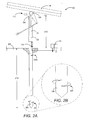
- FIGURE 2A a side view of the installed solar power system 100 is shown. It can be seen that the control box 128 is connected to an external supply box 202 that supplies power and/or other control signals to the solar tracking mechanism 112. According to one aspect of this disclosure, the solar power system components are grounded to the helical anchor 110 via the grounding connection 218. Because the helical anchor 110 is manufactured from a conductive material and is screwed directly into the ground 208, the helical anchor 110 provides a convenient ground for all electrical components of the system.
- the helical anchor 110 is a one-piece apparatus that includes an above-ground portion that supports the solar array 106 a height 210 between a top end 204 of the helical anchor 110 and the ground 208.
- An underground portion of the helical anchor 110 extends a depth 212 between a bottom end 206 of the helical anchor 110 and the surface of the ground 208. This underground portion of the helical anchor 110 replaces the traditional concrete foundation used in common solar power system installations.
- the helical anchor 110 is distinguished from any other type of anchoring system that utilizes an underground anchor and an above-ground structure that is then bolted to the underground anchor.
- the helical anchor 110 offers the benefit of requiring fewer parts to manufacture, stock, maintain, and transport, as well as saving installation time since no above ground structure is bolted to the below ground anchor at ground level.
- the height 210 is approximately one half of the depth 212. More specifically, according to one implementation, the helical anchor 110 is approximately 15 feet in length with an above-ground height 210 of 5 feet and an underground depth 212 of 10 feet. According to this implementation, the helical anchor 110 may be manufactured from a steel pipe, be between 6-9 inches in diameter, and have a wall thickness of between 0.25-0.30 inches. This helical anchor 110 could adequately support a rectangular solar array as shown in FIGURE 1 of approximately 8 feet by 18 feet, depending on the soil conditions and the corresponding configuration of the helical anchor 110. It should be understood that the precise characteristics of the helical anchor 110, including the height 210 and depth 212, is dependent at least upon the soil characteristics of the selected installation site, as will be described in greater detail below.
- the helical anchor 110 includes at least one helical anchor blade 220.
- the helical anchor blade 220 is a helical structure that wraps around at least the bottom end 206 of the helical anchor 110 to permit the helical anchor 110 to be screwed into the ground 208.
- the bottom end 206 may be tapered or pointed, as shown, to facilitate ground penetration.
- the helical anchor blade 220 may wrap around the helical anchor 110 any number of rotations, including a single rotation, or 360 degrees, as shown in FIGURES 2A and 2B .
- the helical anchor blade 220 may wrap multiple times around the helical anchor 110 such that a larger percentage of the underground portion of the helical anchor 110 is encompassed by helical anchor blade 220 turns.
- the characteristics of the helical anchor blade 220 and corresponding helical anchor 110 may be dependent on the particular soil conditions of the installation site given the anticipated loads on the helical anchor 110 being installed.
- one or more secondary helical anchor blades 220A may be welded or otherwise attached to the helical anchor 110 at a location along the shaft of the anchor that is spaced apart from the helical anchor blade 220 located at the bottom end 206.
- a secondary helical anchor blade 220A may be attached to the helical anchor 110 at a location that is approximately one foot below ground level, as shown in FIGURE 2A . Doing so further secures the helical anchor 110 to the ground 208 at a location proximate to the surface to absorb the excess loads and consequently, further reduce deflections of the above-ground portion of the helical anchor 110.
- the helical anchor blade 220 has a pitch 224 that is equivalent to the distance along the axis of the helical anchor 110 that is covered by one complete rotation of the helical anchor blade 220.
- the inside diameter 226 of the helical anchor blade 220 is substantially equivalent to the outside diameter of the helical anchor 110 around which the helical anchor blade 220 is wrapped.
- the helical anchor blade 220 may be welded or otherwise attached to the helical anchor 110 by any suitable means.
- the outside diameter 228 of the helical anchor blade 220 is the distance between the outermost edges of the helical anchor blade 220 on opposing sides of the helical anchor 110. The difference between the outside diameter 228 and the inside diameter 226 defines the width of the helical anchor blade 220.
- FIGURE 4B shows an alternative implementation in which the solar tracking mechanism 112, with the attached solar array 106, is secured to the helical anchor 110 without fasteners or welding.
- the solar tracking mechanism 112 has a tapered portion 410 that fits inside an open top end 204 of the helical anchor 110.
- the tapered portion 410 of the solar tracking mechanism 112 has a taper that corresponds to an inner tapered portion 412 of the open top end 204 so that it may be easily inserted into the open top end 204 of the helical anchor 110.
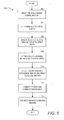
- the routine 500 begins at operation 502, where a helical anchor 110 configuration is selected. As described above, this configuration selection is going to depend in part upon the characteristics of the installation location, and particularly of the soil conditions at that location. The number of turns of the helical anchor blade 220, the pitch of the helical anchor blade 220, and the outside diameter 228 of the helical anchor blade 220 may all be factors that are dependent upon the soil characteristics.
- Known soil analysis techniques may be used to determine the characteristics of the soil at the installation location. Based on this analysis, any number of helical anchor features discussed above may be selected and utilized to predict the load bearing capacity of the selected helical anchor. This predicted load-bearing capacity may be compared with the predicted loads to be experienced by the helical anchor 110 at that location to determine if the selected anchor configuration is acceptable. If not, further engineering analysis may be performed utilizing various anchor characteristics until a configuration of the helical anchor 110 that meets all predicted load-bearing requirements has been selected.
- the helical anchor 110 configuration may also include material considerations. For example, depending on the environmental conditions to which the solar power system 100 will be exposed, the type of material used to manufacture the helical anchor 110 and corresponding helical anchor blade 220, the outside diameter of the helical anchor 110 and inside diameter 226 of the helical anchor blade 220, the thickness of the material, and the total length of the helical anchor 110 may change. To decrease the material and installation costs, the least robust helical anchor 110 configuration may be selected that will sustain safe operations of the solar power system 100 according to the environmental conditions at the specific installation location.
- the routine 500 continues from operation 502 to operation 504, where the installation depth 212 is determined.
- the depth 212 is dependent upon soil and environmental conditions at the installation site. If the solar power system 100 is to be subjected to large wind loads with relatively loose soil conditions, then the depth 212 would be greater than if the solar power system 100 is to be subjected to very light wind loads and compact soil. Structural analysis of the loads to carried by the helical anchor 110 can be used to select an acceptable installation depth 212.
- routine 500 continues to operation 506, where the selected helical anchor 110 is screwed into the ground 208 at the installation location to the proper installation depth 212.
- the solar tracking mechanism 112 is bolted or otherwise attached to the solar array 106 at operation 508.
- the routine 500 continues from operation 508 to operation 510, where the solar tracking mechanism 112, with the attached solar array 106, is attached to the helical anchor 110. As described above with respect to FIGURE 4A , this may occur by bolting the solar tracking mechanism 112 to a mast cap 402 attached to the top end 204 of the helical anchor 110.
- the solar tracking mechanism 112 may include a tapered portion 410 that is inserted into an open top end 204 of the helical anchor 110 until frictionally engaged and secured in place by the weight of the solar array 106.
- the power and communication wires are connected between the control box 128 and the external supply box 202, and to the applicable components of the solar power system 100.
- This operation may include the connection of any applicable air or hydraulic lines if utilized by the solar tracking mechanism 112 as described above.
- This operation may also include connecting the solar tracking mechanism 112 to a controller that provides the appropriate control signal input to the solar tracking mechanism in order to accurately track the movement of the sun.
- the controller may be within the control box 128, the external supply box 202, or may be a part of the solar tracking mechanism 112.
- the ground wires are connected to the grounding connection 218 of the helical anchor 110 to ground the electrical components of the solar power system at operation 514, and the routine 500 ends.
- the helical anchor 110 and corresponding method of installation provides a significant reduction in the amount of time and money required to install solar power systems.
- the helical anchor 110 described herein allows for a simplified installation that includes merely screwing the appropriate anchor in the ground. Not only does this process save installation time, but the reduction in the required materials also saves money in manufacturing, storing, maintaining, and transporting those materials to the installation sites. Reducing the time and costs associated with solar power systems and corresponding installations of these systems will advance the use of solar power as an alternative energy source as these systems become commercially viable for a larger number of energy applications.
Landscapes
- Engineering & Computer Science (AREA)
- Physics & Mathematics (AREA)
- Life Sciences & Earth Sciences (AREA)
- Sustainable Development (AREA)
- Sustainable Energy (AREA)
- Thermal Sciences (AREA)
- Chemical & Material Sciences (AREA)
- Combustion & Propulsion (AREA)
- Mechanical Engineering (AREA)
- General Engineering & Computer Science (AREA)
- Piles And Underground Anchors (AREA)
- Photovoltaic Devices (AREA)
Applications Claiming Priority (1)
| Application Number | Priority Date | Filing Date | Title |
|---|---|---|---|
| US12/613,252 US20110099923A1 (en) | 2009-11-05 | 2009-11-05 | Solar Array Foundation and Installation |
Publications (2)
| Publication Number | Publication Date |
|---|---|
| EP2320156A2 true EP2320156A2 (de) | 2011-05-11 |
| EP2320156A3 EP2320156A3 (de) | 2012-02-08 |
Family
ID=43589572
Family Applications (1)
| Application Number | Title | Priority Date | Filing Date |
|---|---|---|---|
| EP10176410A Withdrawn EP2320156A3 (de) | 2009-11-05 | 2010-09-13 | Solaranordnungsfundament und Installationsverfahren |
Country Status (4)
| Country | Link |
|---|---|
| US (1) | US20110099923A1 (de) |
| EP (1) | EP2320156A3 (de) |
| CN (1) | CN102130204A (de) |
| AU (1) | AU2010212351A1 (de) |
Cited By (4)
| Publication number | Priority date | Publication date | Assignee | Title |
|---|---|---|---|---|
| DE102011004662A1 (de) * | 2011-02-24 | 2012-08-30 | Siemens Aktiengesellschaft | Nachführsystem für eine Solaranlage |
| EP2584283A1 (de) | 2011-10-20 | 2013-04-24 | A&A Civil Engineering Consultants Ltd. | Verfahren und Vorrichtung zur Hangsicherung mit zusätzlicher Anordnung von Photovoltaikelementen zur Energiegewinnung |
| EP2857613A4 (de) * | 2012-05-31 | 2016-01-20 | Daikin Ind Ltd | Photovoltaiktafeleinheit, photovoltaisches stromerzeugungssystem und verfahren zur installation des photovoltaischen stromerzeugungssystems |
| EP2607819A3 (de) * | 2011-12-19 | 2017-06-28 | Artur Deger | Bewegungseinrichtung, Aufbau, Nachführvorrichtung, Solarsystem und Herstellverfahren |
Families Citing this family (23)
| Publication number | Priority date | Publication date | Assignee | Title |
|---|---|---|---|---|
| WO2008124642A2 (en) * | 2007-04-04 | 2008-10-16 | Thompson Technology Industries, Inc. | Adjustable tilt slar panel support system |
| US20160093756A9 (en) * | 2009-11-24 | 2016-03-31 | Charles Silver | Solar Photovoltaic Support and Tracking System with vertical adjustment capability |
| CA2777181C (en) | 2011-05-17 | 2015-02-17 | Wilbur L. Anderson, Inc. D/B/A Western Towers | A tilt tower assembly and a method of using the same, and a method to ship and assemble a tilt tower |
| FR2976058B1 (fr) * | 2011-05-30 | 2013-07-05 | Prestige Solaire | Systeme motorise d'entrainement en rotation pour un systeme de support suiveur pour capteur solaire |
| US20130098858A1 (en) * | 2011-09-27 | 2013-04-25 | Northern States Metals Company | Support system for solar panels with modified joists |
| US9466749B1 (en) | 2012-12-10 | 2016-10-11 | Nextracker Inc. | Balanced solar tracker clamp |
| US10008975B2 (en) | 2012-12-10 | 2018-06-26 | Nextracker Inc. | Clamp assembly for solar tracker |
| US9766319B2 (en) | 2012-12-10 | 2017-09-19 | Nextracker Inc. | Off-set drive assembly for solar tracker |
| CN104969464B (zh) | 2012-12-10 | 2018-09-21 | 耐克斯特拉克尔有限公司 | 水平平衡的太阳能跟踪器 |
| US8863450B2 (en) | 2013-03-11 | 2014-10-21 | Paula C. Anderson | Tilt tower and pipe auger anchor assembly |
| CN103266793B (zh) * | 2013-05-29 | 2015-04-01 | 苏州聚晟太阳能有限公司 | 单轴联动跟踪太阳能充电车棚 |
| US20180175782A1 (en) * | 2016-12-20 | 2018-06-21 | Sane Innovations, LLC. | Support Structure for Maximizing Solar-Panel Efficiency and Facilitating Solar-Panel Installation |
| US10119291B2 (en) * | 2017-02-17 | 2018-11-06 | James McKinion | Free-standing load support system |
| US12323087B2 (en) * | 2017-07-14 | 2025-06-03 | Watershed Geosynthetics Llc | Anchoring structure for ground mounting of solar photovoltaic system |
| CN116667750A (zh) * | 2017-11-21 | 2023-08-29 | 斯蒂芬·凯莱赫 | 接地安装组件 |
| US10697490B2 (en) | 2018-07-24 | 2020-06-30 | Ojjo, Inc. | Threaded truss foundations and related systems, methods, and machines |
| USD913780S1 (en) * | 2019-03-28 | 2021-03-23 | Ojjo, Inc. | Helical anchor |
| US11401675B2 (en) * | 2019-07-16 | 2022-08-02 | Ojjo, Inc. | Axially adjustable connectors for truss legs and related systems and methods |
| WO2022040194A1 (en) * | 2020-08-17 | 2022-02-24 | Nextracker Inc. | Multiple wall connection over piers |
| EP4417895B1 (de) | 2020-09-14 | 2025-11-05 | Nextracker Inc. | Dämpfermontage für sonnenfolger |
| US20220109395A1 (en) * | 2020-10-02 | 2022-04-07 | National Christmas Products Llc | System, apparatus, and method for providing a power source |
| US12222138B2 (en) | 2021-05-24 | 2025-02-11 | Helical Solar Solutions, LLC | Free-standing load support system |
| WO2025111182A1 (en) * | 2023-11-21 | 2025-05-30 | Nextracker Llc | In-situ solar tracker manufacturing |
Family Cites Families (23)
| Publication number | Priority date | Publication date | Assignee | Title |
|---|---|---|---|---|
| US4252107A (en) * | 1978-04-20 | 1981-02-24 | General Electric Company | Solar tracking concentrator |
| US4459972A (en) * | 1981-10-06 | 1984-07-17 | Veda Incorporated | Heliostat assembly |
| US4890599A (en) * | 1987-04-16 | 1990-01-02 | Eiden Glenn E | Solar panel mounting assembly |
| US5143556A (en) * | 1989-03-13 | 1992-09-01 | Matlin Ronald W | Support for photovoltaic arrays |
| WO1990012990A1 (en) * | 1989-04-25 | 1990-11-01 | Glasstech, Inc. | Photovoltaic panel support assembly |
| DE4036938A1 (de) * | 1990-11-20 | 1992-05-21 | Drescher Ruediger | Solarturmkraftwerk |
| WO1993012312A1 (en) * | 1991-12-12 | 1993-06-24 | Instant Foundations (Aust.) Pty. Ltd. | Ground anchors |
| US5285614A (en) * | 1992-07-16 | 1994-02-15 | Sherman Utility Structures, Inc. | Concrete pole splice |
| US5408788A (en) * | 1993-08-27 | 1995-04-25 | Hubbell Incorporated | Hollow hub helical earth anchor with improved earth penetrating spade/pilot point |
| US6199569B1 (en) * | 1996-04-10 | 2001-03-13 | Bobby L. Gibson | Compact umbrella anchor and method |
| US5819477A (en) * | 1996-09-16 | 1998-10-13 | Hurricane Straps Inc. | Apparatus and methods for securing a building |
| US6191355B1 (en) * | 1997-11-28 | 2001-02-20 | Hans P. Edelstein | Multi-sectional utility pole having slip-joint conical connections |
| US6050740A (en) * | 1998-07-20 | 2000-04-18 | Dixie Electrical Manufacturing Company | Combined lockdog and kelly bar adapter |
| DE19836370C2 (de) * | 1998-08-11 | 2002-07-18 | Klaus Krinner | Verfahren zur Herstellung von Befestigungsvorrichtungen für Stäbe, Pfosten,Masten oder dergleichen im Erdreich und nach diesem Verfahren hergestellte Befestigungsvorrichtungen |
| US6814525B1 (en) * | 2000-11-14 | 2004-11-09 | Michael Whitsett | Piling apparatus and method of installation |
| US6662801B2 (en) * | 2001-10-02 | 2003-12-16 | Pinnacle West Capital Corporation | Celestial tracking apparatus and method of controlling wind stow therefor |
| JP3967933B2 (ja) * | 2002-02-19 | 2007-08-29 | 旭テック株式会社 | アンカ埋設方法 |
| DE102006022982B4 (de) * | 2006-04-12 | 2014-09-04 | Georg Kredler | Vorrichtung zur Montierung wenigstens eines Solarmoduls zur wenigstens einachsigen Nachführung |
| DE102008011869A1 (de) * | 2008-02-29 | 2009-09-10 | Peter Kellner | Schraubfundament |
| DE102008027452B4 (de) * | 2008-04-07 | 2016-02-25 | VISPIRON ENGINEERING GmbH | Aufständerungsvorrichtung für ein Solarmodul |
| US8136460B2 (en) * | 2008-06-09 | 2012-03-20 | Tait Towers, Inc. | Portable locking support and platform system |
| DE202009006970U1 (de) * | 2009-05-14 | 2009-08-06 | Krinner Innovation Gmbh | Ausrichtbares Fundamentsystem für Solarpaneele |
| US20110041752A1 (en) * | 2009-08-19 | 2011-02-24 | Lacivita Anthony | Anchorman marine mooring and docking system |
-
2009
- 2009-11-05 US US12/613,252 patent/US20110099923A1/en not_active Abandoned
-
2010
- 2010-08-13 AU AU2010212351A patent/AU2010212351A1/en not_active Abandoned
- 2010-09-13 EP EP10176410A patent/EP2320156A3/de not_active Withdrawn
- 2010-11-05 CN CN2010105429265A patent/CN102130204A/zh active Pending
Non-Patent Citations (1)
| Title |
|---|
| None |
Cited By (4)
| Publication number | Priority date | Publication date | Assignee | Title |
|---|---|---|---|---|
| DE102011004662A1 (de) * | 2011-02-24 | 2012-08-30 | Siemens Aktiengesellschaft | Nachführsystem für eine Solaranlage |
| EP2584283A1 (de) | 2011-10-20 | 2013-04-24 | A&A Civil Engineering Consultants Ltd. | Verfahren und Vorrichtung zur Hangsicherung mit zusätzlicher Anordnung von Photovoltaikelementen zur Energiegewinnung |
| EP2607819A3 (de) * | 2011-12-19 | 2017-06-28 | Artur Deger | Bewegungseinrichtung, Aufbau, Nachführvorrichtung, Solarsystem und Herstellverfahren |
| EP2857613A4 (de) * | 2012-05-31 | 2016-01-20 | Daikin Ind Ltd | Photovoltaiktafeleinheit, photovoltaisches stromerzeugungssystem und verfahren zur installation des photovoltaischen stromerzeugungssystems |
Also Published As
| Publication number | Publication date |
|---|---|
| AU2010212351A1 (en) | 2011-05-19 |
| US20110099923A1 (en) | 2011-05-05 |
| EP2320156A3 (de) | 2012-02-08 |
| CN102130204A (zh) | 2011-07-20 |
Similar Documents
| Publication | Publication Date | Title |
|---|---|---|
| EP2320156A2 (de) | Solaranordnungsfundament und Installationsverfahren | |
| EP1741928B1 (de) | System und Verfahren zum Installieren einer Offshore-Windkraftanlage | |
| JP2021510793A (ja) | 風力および太陽光発電のためのマルチ風力タービンおよびソーラーを支持する風に対向して自己整列する浮体式プラットフォーム、ならびにその構築方法 | |
| EP3130796B1 (de) | Windturbinenanordnungssystem und zugehöriges verfahren | |
| JP5437029B2 (ja) | 太陽光発電装置の設置構造 | |
| EP3178996B1 (de) | Pfahl für eine offshore-monopile gründung | |
| KR101318111B1 (ko) | 파력 저감형 다열 파일 하이브리드 해상풍력 지지구조물 및 그 시공 방법 | |
| WO2014144327A2 (en) | Ground mounting assembly | |
| CA3057491A1 (en) | Wind turbine foundation and method of constructing a wind turbine foundation | |
| KR20200057954A (ko) | 부분적 리파워링을 위해 기초부를 보강한 풍력발전 구조물 및 그 시공방법 | |
| US20160265514A1 (en) | Support device and methods for improving and constructing a support device | |
| JP2014125808A (ja) | 太陽光発電ユニットおよび太陽光発電システム | |
| JP2003206852A (ja) | 洋上風力発電用支持装置 | |
| GB2505192A (en) | A pile sleeve connection for a monopole foundation | |
| KR101383159B1 (ko) | 암반 설치용 중력식 해상풍력 기초 슬래브 | |
| CN102628277B (zh) | 无过渡段单桩式海上风机基础结构 | |
| JP2013067948A (ja) | 太陽電池モジュール又は太陽電池アレイ用架台の基礎構造 | |
| CN220746998U (zh) | 单桩式海上光伏支承结构 | |
| WO2020198579A2 (en) | Roll-formed solar canopy structures and foundation structures and methods | |
| US20250369654A1 (en) | Hydroformed cylindrical piles | |
| CN208233312U (zh) | 一种海上测风塔 | |
| US20260092422A1 (en) | Screw pile with an anti-tip panel | |
| CN207017250U (zh) | 一种农光互补光伏管桩 | |
| CN218787021U (zh) | 一种立柱及定日镜 | |
| CN220318543U (zh) | 一种用于异形基坑侧壁的辅助支撑结构 |
Legal Events
| Date | Code | Title | Description |
|---|---|---|---|
| PUAI | Public reference made under article 153(3) epc to a published international application that has entered the european phase |
Free format text: ORIGINAL CODE: 0009012 |
|
| 17P | Request for examination filed |
Effective date: 20100913 |
|
| AK | Designated contracting states |
Kind code of ref document: A2 Designated state(s): AL AT BE BG CH CY CZ DE DK EE ES FI FR GB GR HR HU IE IS IT LI LT LU LV MC MK MT NL NO PL PT RO SE SI SK SM TR |
|
| AX | Request for extension of the european patent |
Extension state: BA ME RS |
|
| PUAL | Search report despatched |
Free format text: ORIGINAL CODE: 0009013 |
|
| AK | Designated contracting states |
Kind code of ref document: A3 Designated state(s): AL AT BE BG CH CY CZ DE DK EE ES FI FR GB GR HR HU IE IS IT LI LT LU LV MC MK MT NL NO PL PT RO SE SI SK SM TR |
|
| AX | Request for extension of the european patent |
Extension state: BA ME RS |
|
| RIC1 | Information provided on ipc code assigned before grant |
Ipc: F24J 2/54 20060101ALI20120105BHEP Ipc: F24J 2/52 20060101AFI20120105BHEP |
|
| STAA | Information on the status of an ep patent application or granted ep patent |
Free format text: STATUS: THE APPLICATION IS DEEMED TO BE WITHDRAWN |
|
| 18D | Application deemed to be withdrawn |
Effective date: 20120809 |