EP2582526B1 - Druckkopfmodul - Google Patents
Druckkopfmodul Download PDFInfo
- Publication number
- EP2582526B1 EP2582526B1 EP10734031.7A EP10734031A EP2582526B1 EP 2582526 B1 EP2582526 B1 EP 2582526B1 EP 10734031 A EP10734031 A EP 10734031A EP 2582526 B1 EP2582526 B1 EP 2582526B1
- Authority
- EP
- European Patent Office
- Prior art keywords
- head module
- bearing
- housing
- transverse direction
- Prior art date
- Legal status (The legal status is an assumption and is not a legal conclusion. Google has not performed a legal analysis and makes no representation as to the accuracy of the status listed.)
- Active
Links
Images
Classifications
-
- B—PERFORMING OPERATIONS; TRANSPORTING
- B41—PRINTING; LINING MACHINES; TYPEWRITERS; STAMPS
- B41J—TYPEWRITERS; SELECTIVE PRINTING MECHANISMS, i.e. MECHANISMS PRINTING OTHERWISE THAN FROM A FORME; CORRECTION OF TYPOGRAPHICAL ERRORS
- B41J25/00—Actions or mechanisms not otherwise provided for
- B41J25/34—Bodily-changeable print heads or carriages
-
- B—PERFORMING OPERATIONS; TRANSPORTING
- B41—PRINTING; LINING MACHINES; TYPEWRITERS; STAMPS
- B41J—TYPEWRITERS; SELECTIVE PRINTING MECHANISMS, i.e. MECHANISMS PRINTING OTHERWISE THAN FROM A FORME; CORRECTION OF TYPOGRAPHICAL ERRORS
- B41J2/00—Typewriters or selective printing mechanisms characterised by the printing or marking process for which they are designed
- B41J2/485—Typewriters or selective printing mechanisms characterised by the printing or marking process for which they are designed characterised by the process of building-up characters or image elements applicable to two or more kinds of printing or marking processes
- B41J2/505—Typewriters or selective printing mechanisms characterised by the printing or marking process for which they are designed characterised by the process of building-up characters or image elements applicable to two or more kinds of printing or marking processes from an assembly of identical printing elements
- B41J2/515—Typewriters or selective printing mechanisms characterised by the printing or marking process for which they are designed characterised by the process of building-up characters or image elements applicable to two or more kinds of printing or marking processes from an assembly of identical printing elements line printer type
Definitions
- the invention relates to a printhead module for a single-pass inkjet printer, which comprises a housing and a number of printheads arranged on the housing along a transverse direction to a running direction.
- a single pass ink jet printer While in a conventional ink jet printer, the printheads mounted on a carriage transversely spray line by line ink droplets on the discontinuously transported medium, in a single pass ink jet printer the printheads in printhead modules of the initially mentioned type are mounted transversely across the entire width of the media.
- the print medium can be moved continuously in the direction of travel. While printing speeds of up to 2 m per minute are achieved with a conventional inkjet printer, printing speeds of more than 50 m per minute can be achieved with a single-pass inkjet printer.
- a single-pass inkjet printer has multiple printhead modules mounted one behind the other in the direction of travel.
- the printhead modules in each case a basic color, in particular cyan, magenta and yellow and optionally black, assigned. For special print jobs, printhead modules with a special color may be added.
- a single-pass inkjet printer is particularly suitable for industrial use, where quantity must be printed and it therefore depends on a high throughput. Similarly, a single-pass inkjet printer is suitable for printing large-area objects due to the high printing speeds. A single-pass inkjet printer is therefore particularly suitable for industrial applications in the furniture or ceramic industry, where floor coverings, such as laminates or ceramic tiles, worktops, moldings or the like are to be provided with a decor. There are a variety of inks used, the For example, resistant to a later protective coating, etc. are.
- the single-pass inkjet printer is used even for small lot sizes, where the production of a pressure roller is not worthwhile.
- a single-pass inkjet printer also makes it possible to customize the decors, as well as impossible decors that can not be achieved with rollers.
- the single-pass ink jet printer is not limited to a constant repetition of a print pattern or repeat, as is the case with roller printing.
- a printhead module for a single-pass inkjet printer can reach dimensions of more than one-half to over one meter in the transverse direction and in the height.
- the individual print heads combined in the print bar of a printhead module can have widths of up to several 10 cm. It is possible to achieve resolutions up to 600 x 600 dpi (dots per inch). Per printhead this several thousand nozzles are included. By using large printhead modules or by arranging several printhead modules, print widths of up to several meters can be achieved.
- a printhead module of the type mentioned above wherein a housing attached to the Ge vonteil is provided to a gravity-oriented suspension, and wherein the individual arranged on the housing printheads are positionally aligned to at least one reference position.
- the invention is based on the consideration that a hanging attachment of the printhead modules in principle allows easier installation and removal in the vertical direction.
- a suspended printhead module can be easily removed from a fixed printing position, in particular dug, and placed in an accessible cleaning or removal position above or below the printing position.
- a hanging arrangement of the printhead module allows for self-alignment due to the gravitational force applied to the center of gravity. When inserting the hanging printhead module this is already a rough positioning for later fixed device printing position given.
- the suspended fastening allows, in particular, without complex mechanical auxiliary constructions, a self-adjustment of the printhead module into the device-fixed printing position without the need for manual readjustment.
- the structure of any mechanical guide elements is simplified by the automatic positioning of the hanging printhead module by gravity against complex forced guides.
- the mechanical elements provided for this purpose are in particular designed such that only a lowering or raising of the print head module leads to the achievement of the predetermined printing position. By lowering or raising the printhead module this leaves the printing position and can be reversibly returned to this in a simple manner.
- the printhead module may contain, in addition to the printheads, at the same time control electronics and optionally an ink tank.
- control electronics and optionally an ink tank.
- the invention is by no means limited to such comparatively large embodiments.
- the hanger part is preferably designed so that it is used in conjunction with the single-pass inkjet printer as a fixed or floating bearing for determining the final position.
- the hanger part can in particular also be designed such that it can be lifted out of the hanger in the vertical direction. This allows in the final printing position then a stationary attachment of the printhead module. Accordingly, with the suspended insertion, the center of gravity of the printhead module is below the bearing point of the hanger or the hanging part. In the device-fixed printing position reached, however, the center of gravity of the printhead module is arranged above a then resulting lower bearing with a vertical mounting.
- the hanger part is designed as a suspended in a hanger hanging suspension piece.
- a pendulum mounting the printhead module allows, for example via a printer-side lifting-lowering device, the necessary degrees of freedom that are necessary to align the printhead module between its free hanging position and the device fixed printing position.
- the oscillating arrangement can in principle be given by a suitable mechanical suspension.
- cutting or pan bearing are also conceivable as a hanging connection via a flexible connection part, such as a rope element or the like.
- the suspension piece in the latter case, the rope element itself dar.
- the hanging part for example, spherical, conical or shaped like a nipple.
- the suspension of the printhead module is used as a bearing for determining the printing position.
- the suspended parts are designed such that the hinged printhead module can be suspended parallel to the transverse direction and arranged to oscillate about a polar angle.
- aligning the printhead module parallel to the transverse direction an important pre-positioning is achieved.
- the vertical orientation of a transversely extending printhead module to the direction of travel of the print medium is essential to the achievable print quality. Deviation from the vertical angle to the running direction leads to an offset of the individual pressure points in relation to the desired position of the image point in the transverse direction.
- the hanger for the printhead module is for this purpose, for example, designed as a floating bearing, which allows a shift in the transverse direction, but does not allow a degree of freedom in the direction of travel.
- a bearing with the hanger part suitable for this purpose can be designed in particular as a push guide in the transverse direction.
- the suspension piece is preferably formed as a cone piece, which can be suspended in a transversely extending prism or wedge sink or the like.
- the opening angle of the cone is in particular smaller than that of the prism or wedge recess. If the pan is open in particular on one side in the transverse direction, the printhead module can be suspended and removed in a simple manner.
- At least two offset in the transverse direction hanging parts are provided. In this way, the desired parallel alignment of the printhead module to the transverse direction upon hooking is inevitably achieved.
- catching means are arranged on the housing for coarse positioning in relation to a designated printing position.
- these catching means serve for the coarse positioning of the incoming, in particular sinking printhead module.
- a particular pendulum suspended printhead module will align its center of gravity when inserted by gravity.
- the catching means are then designed so that they are able to detect any device-fixed positioning elements during movement of the print head module, in particular when lowering, and to pre-position the latter with respect to the final printing position.
- the catch means are formed by a catch wedge or by a wedge shaft. If, for example, a wedge shaft mounted on the housing of the printhead module is provided, then it can cooperate with a device-fixed catch wedge. When moving gradually, in particular lowering the printhead module in the printing position of the wedge shaft first takes the device fixed wedge tip and then the entire wedge, whereby the print head module in its still possible degrees of freedom, for example, a displacement in the transverse direction or a pendulum motion to the polar angle, further limited. As a result of the catching means, the printhead module is forcibly directed to the later specified printing position. Conversely, a catch wedge mounted on the housing of the printhead module can interact in the same way with a wedge shaft mounted on the device.
- the catch wedge or the wedge shaft is formed into a substantial vertical thrust guide with a corresponding counterpart.
- a thrust guide By such a thrust guide, a further movement of the print head module in the vertical direction is possible with simultaneous prepositioning in the transverse direction.
- a catch angle oriented parallel to the direction of rotation or a groove recess aligned parallel to the direction of rotation is provided as catching means.
- About the aligned in the direction of catch catching the polar angle is increasingly determined during the movement of the print head module in the printing position.
- Nutseke the printhead module is set in the transverse direction.
- At least two offset in the transverse direction bearing pieces are arranged on the housing, which are each designed for a self-aligning positioning in an open bearing.
- the self-aligning bearings in the vertical direction need not be complicated in construction. It is only necessary that the two bearing elements realizing the bearing automatically find each other during gradual introduction of the printhead module, whereby finally the final position is determined.
- Suitable bearing pieces are designed to cooperate with, for example, a ladle, cutting or tip bearing.
- the bearing pieces can be designed in particular conical, conical, angular, pointed or spherical.
- the bearing pieces are height-adjustable mounted on the housing. In this way, production-related dimensional tolerances can be compensated or the print heads can be adjusted to the printing position in height.
- one of the bearing pieces is designed for positioning in a fixed and the other of the bearing pieces for positioning in a movable bearing in the transverse direction.
- an extension of the print head module in the transverse direction can be intercepted via the floating bearing.
- each of the fixed bearing is designed as a ball journal bearing and given the floating bearing by a prismatic slide in the transverse direction.
- the bearing pieces are preferably each formed as a ball stud.
- the fixed bearing is then advantageously equipped for a punctiform pivot bearing with a conical socket into which the ball end of the pin is received and positioned during vertical insertion of the printhead module.
- the prismatic slide guide is also designed as a ball-and-socket bearing, wherein, however, the socket is designed with a prismatic cross-section along the transverse direction.
- the prism guide then sets the parallel position of the printhead module to the transverse direction. In the transverse direction itself, a linear offset is still possible as a degree of freedom.
- a stop piece is arranged on the abutment surface on the printhead module for abutment.
- Such a stop piece is aimed in particular the inclination of the printhead module to the polar angle, if the hanger does not restrict a degree of freedom in the direction of travel entirely. This is particularly the case when the printhead module is formed into a standing fixture in the final printing position with the hanging pieces dug out of the hanger.
- the stop piece comprises a transversely extending ball pin.
- a device fixed stop surface which positions the ball pin in the running direction final.
- a ball pin allows, together with an example spherical stop surface regardless of the vertical height a defined stop.
- the respective printhead module is then precisely defined, for example, by the two open bearings, namely a ball and socket bearing as a fixed bearing and a prismatic slide as a floating bearing, and by the stop piece ajar to the stop surface.
- the stop piece By ajar stop piece in particular the inclination or polar angle is set.
- the corresponding guide takes over the stop piece in interaction with the device-fixed vertical stop surface.
- Another essential aspect of the invention is the positional adjustment of the print heads to at least one reference position.
- these are always identically aligned upon reaching the final print position of the printhead module except for unavoidable dimensional tolerances.
- each printhead module always has the same positional orientation of its respective printheads with respect to at least one reference position.
- a simple replacement of the printhead modules is achieved.
- the position of the printheads of the replaced and the newly installed printhead module are identical with regard to the device side.
- the print heads are mounted displaceably in the print head module, for example, in the transverse direction and in the direction of travel.
- the printhead module is brought to a similar position to the later printing position before delivery for positional adjustment.
- the individual print heads are adjusted for example by light microscopy in the micrometer range to a reference position position.
- the printheads are each positionally aligned to the bearing pieces, such as the ball stud.
- the printhead modules are introduced before delivery in the corresponding workpiece according to the later printing position.
- This tool has the same bearings as the later single pass inkjet printer. Since the print head module is exactly positioned in the tool via the two transversely offset bearing pieces as well as by the suspension, the print heads can in particular be parallelized and aligned in the transverse and in the direction of travel. The height of the print heads, for example, can then be made via the height-adjustable bearing pieces.
- the housing further preferably comprises a number of air slots, wherein an air supply is provided in the housing interior.
- an air supply is provided in the housing interior.
- the document WO 2 005 108 094 shows a suspension printhead.
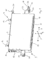
- Fig. 1 shows a printhead module 1 with a housing 3, at the top two suspension parts 4 are arranged.
- the hanger parts 4 enable the single-pass inkjet printer to have a hanging insertion of the printhead module 1 in order to achieve a later device-fixed printing position.
- Fig. 1 For orientation are in Fig. 1 the running direction 7 of a corresponding pressure medium, the transverse direction 8 perpendicular thereto and the vertical direction 9 are drawn. In the device-fixed printing position, the printing medium moves in the direction 7 under the printhead module 1 away.
- each printhead 10 comprises a number of nozzles held in a respective frame.
- the printhead module 1 further includes a number of ports 12 for supplying power, control signals, and ink. Inside the housing 3, the control electronics for driving the print heads 10 and an ink tank are housed.
- the housing 3 comprises a number of louvers 15 and an air inlet 16.
- About the air inlet 16 is introduced from the outside compressed air, which in particular on the louvers 15 again passes to the outside. This way will Keep dust or other contamination away from the printhead module 1.
- the hanging parts 4 are each formed as suspension pieces 19, which allow a pendulum suspension in a corresponding pan bearing.
- the suspension pieces 19 are each formed as conical pieces 20.
- the conical pieces 20 have a smaller angle of inclination than the pan of the corresponding bearing. Due to the offset in the transverse direction arrangement of the two conical pieces 20 takes place when attaching the printhead module 1 already its orientation parallel to the transverse direction 8.
- the two conical pieces 20 then allow in the corresponding pan bearing oscillation of the printhead module 1 by a polar angle. In other words, the printhead module 1 will align by gravity after hanging substantially in the vertical direction.
- the provided hanger parts 4 also allow the adjustment of an angle of inclination or polar angle in order to adjust the pressure bar with the printing heads 10 parallel to the path of the printing medium.
- the web of the printing medium may be formed, for example, as a curved arc, which allows a tighter management of the pressure medium.
- bearing pieces 23, 24 are mounted.
- each bearing pieces 23, 24 each have a height-adjustable ball studs 27, 28 is attached.
- each catching means 30 are mounted on the two bearing pieces 23, 24, wherein only the in Fig. 1 right catch 30 is located.
- the catching means 30 comprises a wedge shaft 32, which is open in the vertical direction 9 and has a groove groove 33 extending in the transverse direction 7 on its underside.
- a lifting-lowering device of a single-pass inkjet printer printhead module 1 reach the catch means 30 gradually in position with a corresponding Counterpart to the printer.
- This counterpart is in each case designed as a catch wedge oriented in the direction of travel 7.
- This catching wedge is first grasped by the groove groove 33 and slides into the vertical wedge shaft 32.
- Fang wedge of the single-pass inkjet printer and wedge shaft 32 each form a vertical slide guide in both bearing pieces 23, 24.
- the printhead module 1 Upon further lowering, the printhead module 1 aligns in the polar angle and in the transverse direction, since the catching means 30 gradually slide completely onto the device-fixed catching wedge. The catch means 30 thus cause a coarse positioning of the print head module 1 in its lowering relative to the final print position to be reached.
- one of the ball and socket bearings comprises a device-resistant pan with a countersink.
- the other of the two bearings comprises a prismatic recess extending in the transverse direction 8.
- the ball of the ball pin 27 forms, for example, with the conical countersink a three-dimensional fixed pivot point.
- the ball of the opposite ball pin 28 defines the position of the bearing piece 24 in the vertical direction 9 and 7 in the direction. In the transverse direction 8 a shift is possible due to the prismatic sink, whereby longitudinal extensions of the print head module 1 are collected.
- a stop piece 35 is provided on the upper side of the housing 3, which comprises a ball pin 37. This ball pin 37 comes laterally at a lowering of the printhead module 1 to a biased, spherical stop surface of the single-pass ink jet printer. This ensures that when digging the conical pieces 20 in the reached printing position of the inclination angle of the printhead module 1 is exactly defined.
- the printhead module 1 is limited by the provided three bearings in all degrees of freedom and thus accurately positioned.
- the stopper 35 is not mandatory.
- the hanger can be designed as a cutting edge bearing, which defines a pivot point exactly.
- the hanger in the printing position does not need to be excavated.
- the respective print heads 10 are aligned with respect to the balls of the ball studs 27, 28 in the direction 7 and in the transverse direction 8. At a later device fixed printing position, the print heads 10 are adjusted by height adjustment of the ball studs 27, 28 in the vertical direction 9.
- the position adjustment in the transverse direction 8 and in the running direction 7 of the push buttons 10 is effected by a longitudinally displaceable mounting in the housing 3.
- the position adjustment itself is made by light microscopy.
- the printhead module 1 shown is used with its bearings in a suitable tool that forms an identical storage of the later printing position.
Description
- Die Erfindung betrifft ein Druckkopfmodul für einen Single-Pass-Tintenstrahldrucker, welches ein Gehäuse sowie eine Anzahl von entlang einer zu einer Laufrichtung senkrechten Querrichtung am Gehäuse angeordneten Druckköpfen umfasst.
- Während bei einem herkömmlichen Tintenstrahldrucker die auf einem Schlitten montierten Druckköpfe in Querrichtung zeilenweise Tintentropfen auf das in Laufrichtung diskontinuierlich transportierte Medium sprühen, sind bei einem Single-Pass-Tintenstrahldrucker die Druckköpfe in Druckkopfmodulen der eingangs genannten Art in Querrichtung über die gesamte Breite des Mediums montiert. Das Druckmedium kann kontinuierlich in Laufrichtung bewegt werden. Während bei einem konventionellen Tintenstrahldrucker Druckgeschwindigkeiten bis zu 2 m pro Minute erreicht werden, lassen sich mit einem Single-Pass-Tintenstrahldrucker Druckgeschwindigkeiten bis über 50 m pro Minute erzielen. Zum Farbdruck sind bei einem Single-Pass-Tintenstrahldrucker mehrere Druckkopfmodule in Laufrichtung hintereinander montiert. Den Druckkopfmodulen ist dabei jeweils eine Grundfarbe, insbesondere Cyan, Magenta und Gelb sowie gegebenenfalls Schwarz, zugeordnet. Für besondere Druckeinsätze können Druckkopfmodule mit einer Spezialfarbe hinzugefügt sein.
- Ein Single-Pass-Tintenstrahldrucker eignet sich insbesondere für den industriellen Einsatz, bei dem Mengenware bedruckt werden muss und es somit auf einen hohen Durchsatz ankommt. Ebenso eignet sich ein Single-Pass-Tintenstrahtdrucker aufgrund der hohen Druckgeschwindigkeiten zum Bedrucken großflächiger Objekte. Ein Single-Pass-Tintenstrahldrucker eignet sich daher insbesondere für Industrieanwendungen der Möbel- oder Keramikindustrie, wo Bodenbeläge, wie Laminate oder Keramikfliesen, Arbeitsplatten, Profilleisten oder dergleichen mit einem Dekor zu versehen sind. Dabei kommen verschiedenste Tinten zum Einsatz, die beispielsweise widerstandsfähig gegenüber einem späteren Schutzüberzug etc. sind.
- Gegenüber herkömmlichen Druckverfahren, wie beispielsweise Tiefdruck oder dergleichen, kommt der Single-Pass-Tintenstrahldrucker gerade auch bei kleinen Losgrößen zum Einsatz, wo sich die Herstellung einer Druckwalze nicht lohnt. Ein Single-Pass-Tintenstrahldrucker ermöglicht demgegenüber auch eine Individualisierung der Dekors sowie unmögliche Dekors, die mit Walzen nicht erzielbar sind. Der Single-Pass-Tintenstrahldrucker ist nicht auf eine beständige Wiederholung eines Druckmusters oder Rapports beschränkt, wie dies bei einem Walzendruck der Fall ist.
- Ein Druckkopfmodul für einen Single-Pass-Tintenstrahldrucker kann in Querrichtung und in der Höhe durchaus Abmessungen von mehr als einem halben bis über einen Meter hinaus erreichen. Die im Druckbalken eines Druckkopfmoduls zusammengefassten einzelnen Druckköpfe können Breiten bis zu einigen 10 cm aufweisen. Dabei sind Auflösungen bis zu 600 x 600 dpi (dots per inch) möglich. Pro Druckkopf sind hierbei mehrere tausend Düsen enthalten. Durch große Druckkopfmodule oder durch nebeneinander Anordnen mehrerer Druckkopfmodule können Druckbreiten bis zu einigen Metern erzielt werden.
- Mit dem menschlichen Auge sind in einem Druckbild Lageabweichungen von wenigen Mikrometern sichtbar. Bei den oben genannten Auflösungen liegen die einzelnen Düsen eines Druckkopfes nur einige 10 µm auseinander. Die Größe eines Bildpunkts bewegt sich selbst im Bereich von 10 µm. Es wird ersichtlich, dass bei einem Single-Pass-Tintenstrahldrucker mit mehreren in Laufrichtung hintereinander angeordneten Druckkopfmodulen eine Justierung der Druckköpfe im Mikrometer-Bereich notwendig wird, um ein qualitativ hochwertiges Druckbild zu erzeugen. Die Justierung eines Druckkopfmoduls in einem Single-Pass-Tintenstrahldrucker ist daher aufwändig. Die Lage der Druckköpfe muss beispielsweise lichtmikroskopisch erfasst und manuell aufwändig eingestellt werden. So ist der Aufbau eines Single-Pass-Tintenstrahldruckers verhältnismäßig langwierig. Auch für jeden Austausch eines Druckkopfmoduls muss eine Justierung durchgeführt werden. Dies führt zu einer unnötigen Verlängerung der Stillstandzeiten.
- Es ist Aufgabe der Erfindung, ein Druckkopfmodul für einen Single-Pass-Tinten-strahldrucker anzugeben, welches möglichst rasch und einfach ausgetauscht werden kann. Auch soll der Aufbau eines Single-Pass-Tintenstrahldruckers mit einem derartigen Druckkopfmodul möglichst rasch vorgenommen werden können.
- Die genannte Aufgabe wird erfindungsgemäß durch ein Druckkopfmodul der eingangs genannten Art gelöst, wobei ein am Gehäuse befestigtes Gehängeteil zu einer schwerkraftausgerichteten Aufhängung vorgesehen ist, und wobei die einzelnen am Gehäuse angeordneten Druckköpfe zu mindestens einer Referenzposition lagejustiert sind.
- Die Erfindung geht dabei von der Überlegung aus, dass eine hängende Befestigung der Druckkopfmodule grundsätzlich einen erleichterten Einbau und Ausbau in vertikaler Richtung ermöglicht. Ein hängendes Druckkopfmodul kann beispielsweise leicht aus einer gerätefesten Druckposition herausgenommen, insbesondere ausgehoben werden, und in eine zugängliche Reinigungs- oder Entnahmeposition ober- oder unterhalb der Druckposition gebracht werden. Zugleich erlaubt eine hängende Anordnung des Druckkopfmoduls eine Selbstausrichtung aufgrund der am Schwerpunkt angreifenden Schwerkraft. Beim Einsetzen des hängenden Druckkopfmoduls ist hierdurch bereits eine Grobpositionierung zur späteren gerätefesten Druckposition gegeben. Dadurch ermöglicht die hängende Befestigung insbesondere ohne aufwändige mechanische Hilfskonstruktionen eine Selbstjus-tierung des Druckkopfmoduls in die gerätefeste Druckposition, ohne dass eine manuelle Nachjustage notwendig wird. Der Aufbau etwaiger mechanischer Führungselemente ist durch die selbsttätige Positionierung des hängenden Druckkopfmoduls durch Schwerkraft gegenüber aufwändigen Zwangsführungen vereinfacht.
- Auf Seiten des Single-Pass-Tintenstrahldruckers können beispielsweise neben einem Gehänge für das Druckkopfmodul Lager oder Führungselemente vorgesehen sein, die beim Einbringen in einer vertikalen Richtung das Druckkopfmodul in die festgelegte, endgültige Druckposition bringen. Die hierfür vorgesehenen mechanischen Elemente sind insbesondere so ausgestaltet, dass allein ein Absenken oder Anheben des Druckkopfmoduls zum Erreichen der festgelegten Druckposition führt. Durch Absenken oder Anheben des Druckkopfmoduls verlässt dieses die Druckposition und kann in diese in einfacher Art und Weise reversibel wieder zurückgeführt werden.
- Das Druckkopfmodul kann insbesondere neben den Druckköpfen zugleich eine Steuerelektronik sowie gegebenenfalls einen Tintentank enthalten. Die Erfindung ist jedoch auf solche, vergleichsweise großen Ausgestaltungen keinesfalls eingeschränkt.
- Das Gehängeteil ist bevorzugt so ausgebildet, dass es im Zusammenspiel mit dem Single-Pass-Tintenstrahldrucker als ein Fest- oder Loslager zur Festlegung der Endposition verwendet ist. Das Gehängeteil kann insbesondere auch so ausgebildet sein, dass es in vertikaler Richtung dem Gehänge ausgehoben werden kann. Dies erlaubt in der endgültigen Druckposition eine dann stehende Befestigung des Druckkopfmoduls. Bei der hängenden Einführung befindet sich demnach der Schwerpunkt des Druckkopfmoduls unterhalb der Lagerstelle des Gehänges bzw. des Gehängeteils. In der erreichten gerätefesten Druckposition ist bei einer stehenden Befestigung hingegen der Schwerpunkt des Druckkopfmoduls oberhalb einer sich dann ergebenden unteren Lagerstelle angeordnet.
- Bevorzugt ist das Gehängeteil als ein in ein Gehänge pendelnd einhängbares Hängestück ausgebildet. Eine pendelnde Befestigung des Druckkopfmoduls erlaubt beispielsweise über eine druckerseitige Hub-Senk-Einrichtung die notwendigen Freiheitsgrade, die zur Ausrichtung des Druckkopfmoduls zwischen seiner freien Hängeposition und der gerätefesten Druckposition notwendig sind. Die pendelnde Anordnung kann grundsätzlich durch ein geeignetes mechanisches Gehänge gegeben sein. Dabei sind Schneiden- oder Pfannenlager ebenso vorstellbar wie eine hängende Anbindung über ein flexibles Verbindungsteil, wie ein Seilelement oder dergleichen. Das Hängestück stellt in letzterem Fall das Seilelement selbst dar. Ansonsten ist das Gehängeteil beispielsweise kugelig, kegelig oder nach Art eines Nippels ausgebildet.
- Bevorzugt wird die Aufhängung des Druckkopfmoduls als ein Lager zur Festlegung der Druckposition herangezogen. In einer vorteilhaften Ausführungsvariante sind dabei die Gehängeteile so ausgestaltet, dass das eingehängte Druckkopfmodul parallel zur Querrichtung einhängbar und um einen Polarwinkel pendelnd angeordnet ist. Durch die Ausrichtung des Druckkopfmoduls parallel zur Querrichtung wird eine wichtige Vorpositionierung erreicht. Die senkrechte Ausrichtung eines sich in Querrichtung erstreckenden Druckkopfmoduls zur Laufrichtung des Druckmediums ist wesentlich für die erreichbare Druckqualität. Wird von dem senkrechten Winkel zur Laufrichtung abgewichen, so führt dies zu einem Versatz der einzelnen Druckpunkte gegenüber der gewünschten Position des Bildpunktes in Querrichtung. Das Gehänge für das Druckkopfmodul ist hierzu beispielsweise als ein Loslager ausgebildet, welches eine Verschiebung in Querrichtung erlaubt, jedoch keinen Freiheitsgrad in Laufrichtung zulässt. Ein solches Lager mit dem hierzu geeigneten Gehängeteil kann insbesondere als eine Schubführung in Querrichtung ausgebildet sein.
- Bevorzugt ist hierzu das Hängestück als ein Kegelstück ausgebildet, welches in eine in Querrichtung verlaufende Prismen- oder Keilsenke oder dergleichen eingehängt werden kann. Um die Pendelbewegung zu ermöglichen, ist der Öffnungswinkel des Kegels insbesondere kleiner als der der Prismen- oder Keilsenke. Ist die Pfanne insbesondere auf einer Seite in Querrichtung geöffnet, so kann das Druckkopfmodul in einfacher Art und Weise eingehängt und entnommen werden.
- Vorteilhafterweise sind wenigstens zwei in Querrichtung versetzte Gehängeteile vorgesehen. Auf diese Weise wird die gewünschte parallele Ausrichtung des Druckkopfmoduls zur Querrichtung bei Einhängung zwangsläufig erreicht.
- In einer weiter bevorzugten Ausgestaltung sind am Gehäuse Fangmittel zu einer Grobpositionierung im Bezug zu einer vorgesehenen Druckposition angeordnet. In Zusammenspiel mit dem Single-Pass-Tintenstrahldrucker dienen diese Fangmittel zur Grobpositionierung des einlaufenden, insbesondere absinkenden Druckkopfmoduls. Ein insbesondere pendelnd aufgehängtes Druckkopfmodul wird beim Einführen durch die Schwerkraft seinen Schwerpunkt ausrichten. Die Fangmittel sind dann so ausgestaltet, dass sie in der Lage sind, etwaige gerätefeste Positionierungselemente bei Bewegung des Druckkopfmoduls, insbesondere bei einem Absenken, zu erfassen und letzteres gegenüber der endgültigen Druckposition vorzupositionieren.
- In einer vorteilhaften Ausgestaltung sind die Fangmittel durch einen Fangkeil oder durch einen Keilschacht gebildet. Ist beispielsweise ein am Gehäuse des Druckkopfmoduls montierter Keilschacht vorgesehen, so kann dieser mit einem gerätefesten Fangkeil zusammenwirken. Beim allmählichen Bewegen, insbesondere Absenken des Druckkopfmoduls in die Druckposition nimmt der Keilschacht zunächst die gerätefeste Keilspitze und anschließend den gesamten Keil auf, wodurch das Druckkopfmodul in seinen noch möglichen Freiheitsgraden, beispielsweise einen Versatz in Querrichtung oder eine Pendelbewegung um den Polarwinkel, weiter eingeschränkt wird. Durch die Fangmittel wird demnach das Druckkopfmodul gezielt auf die spätere festgelegte Druckposition zwangsgeführt. Umgekehrt kann ein am Gehäuse des Druckkopfmoduls montierter Fangkeil mit einem gerätefest montierten Keilschacht in gleicher Weise zusammenwirken.
- In einer besonders bevorzugten Ausgestaltung ist der Fangkeil oder der Keilschacht zu einer wesentlichen vertikalen Schubführung mit einem entsprechenden Gegenstück ausgebildet. Durch eine solche Schubführung ist bei gleichzeitiger Vorpositionierung in Querrichtung eine weitere Bewegung des Druckkopfmoduls in vertikaler Richtung möglich. Bevorzugt hierbei ist als Fangmittel ein parallel zur Laufrichtung ausgerichteter Fangwinkel oder eine parallel zur Laufrichtung ausgerichtete Nutsenke vorgesehen. Über den in Laufrichtung ausgerichteten Fangkeil wird der Polarwinkel bei der Bewegung des Druckkopfmoduls in die Druckposition zunehmend festgelegt. Über die in Laufrichtung ausgerichtete Nutsenke wird das Druckkopfmodul in Querrichtung festgelegt.
- Vorteilhafterweise sind am Gehäuse wenigstens zwei in Querrichtung versetzte Lagerstücke angeordnet, die jeweils zu einer selbstjustierenden Positionierung in einem offenen Lager ausgebildet sind. Insbesondere wenn Fangmittel vorgesehen sind, brauchen die in Vertikalrichtung selbstjustierenden Lager nicht kompliziert aufgebaut zu sein. Es ist lediglich notwendig, dass die das Lager realisierenden beiden Lagerelemente beim allmählichen Einbringen des Druckkopfmoduls selbsttätig zueinander finden, wodurch letzlich die endgültige Position festgelegt wird. Geeignete Lagerstücke sind zum Zusammenwirken mit beispielsweise einem Pfannen-, Schneiden- oder Spitzenlager ausgebildet. Die Lagerstücke können insofern insbesondere konisch, kegelig, kantig, spitz oder kugelig ausgeführt sein.
- In einer weiter bevorzugten Ausgestaltung sind die Lagerstücke höhenverstellbar am Gehäuse montiert. Auf diese Weise können fertigungsbedingte Maßtoleranzen ausgeglichen oder die Druckköpfe zur Druckposition in der Höhe justiert werden.
- In einer bevorzugten Ausgestaltung ist eines der Lagerstücke zur Positionierung in einem Fest- und das andere der Lagerstücke zur Positionierung in einem Loslager in Querrichtung ausgebildet. Über das Loslager kann beispielsweise eine Ausdehnung des Druckkopfmoduls in Querrichtung abgefangen werden. In einer zweckmäßigen Ausgestaltung ist jeweils das Festlager als ein Kugelzapfenlager ausgebildet und das Loslager durch eine Prismenschubführung in Querrichtung gegeben. Dazu sind die Lagerstücke bevorzugt jeweils als Kugelzapfen ausgebildet. Das Festlager ist dann vorteilhaft zu einer punktförmigen Drehlagerung mit einer Kegelpfanne ausgestattet, in die das Kugelende des Zapfens beim vertikalen Einbringen des Druckkopfmoduls aufgenommen und positioniert wird. Die Prismenschubführung ist insbesondere ebenfalls als ein Kugelzapfenlager ausgestaltet, wobei allerdings die Pfanne mit einem prismenförmigen Querschnitt entlang der Querrichtung ausgestaltet ist. Die Prismenschubführung legt dann die parallele Position des Druckkopfmoduls zur Querrichtung fest. In Querrichtung selbst ist als ein Freiheitsgrad noch ein Linearversatz möglich.
- Weiter bevorzugt ist am Druckkopfmodul ein Anschlagstück zum Anschlag an einer Anschlagfläche angeordnet. Ein solches Anschlagstück richtet insbesondere die Neigung des Druckkopfmoduls um den Polarwinkel aus, sofern das Gehänge einen Freiheitsgrad in Laufrichtung nicht gänzlich einschränkt. Dies ist insbesondere dann der Fall, wenn das Druckkopfmodul zu einer stehenden Befestigung in der endgültigen Druckposition ausgebildet ist, wobei die Hängestücke aus dem Gehänge ausgehoben sind.
- Besonders vorteilhaft umfasst das Anschlagstück einen sich in Querrichtung erstreckenden Kugelzapfen. Bei einer Bewegung des hängenden Druckkopfmoduls in die Druckposition gelangt der Kugelzapfen allmählich in Kontakt mit einer gerätefesten Anschlagfläche, die den Kugelzapfen in Laufrichtung endgültig positioniert. Ein Kugelzapfen erlaubt zusammen mit einer beispielsweise balligen Anschlagfläche unabhängig von der vertikalen Höhe einen definierten Anschlag. In der endgültigen Druckposition ist das jeweilige Druckkopfmodul dann beispielsweise durch die beiden offenen Lager, nämlich einem Kugelzapfenlager als Festlager und einer Prismenschubführung als Loslager, sowie durch das der Anschlagfläche angelehnte Anschlagstück, exakt festgelegt. Durch das angelehnte Anschlagstück ist dabei insbesondere der Neigungs- oder Polarwinkel festgelegt. Die entsprechende Führung übernimmt das Anschlagstück im Zusammenspiel mit der gerätefesten vertikalen Anschlagfläche.
- Ein weiterer wesentlicher Aspekt der Erfindung ist die Lagejustierung der Druckköpfe zu mindestens einer Referenzposition. Durch die Festlegung der Lage der Druckköpfe zu mindestens einer Referenzposition sind diese bei Erreichen der endgültigen Druckposition des Druckkopfmoduls bis auf nicht vermeidbare Maßtoleranzen stets identisch ausgerichtet. Mit anderen Worten weist jedes Druckkopfmodul bezüglich mindestens einer Referenzposition stets dieselbe Lageausrichtung ihrer jeweiligen Druckköpfe auf. Hierdurch wird ein einfacher Austausch der Druckkopfmodule erreicht. Die Lage der Druckköpfe des ausgetauschten und des neu eingesetzten Druckkopfmoduls sind bezüglich der Geräteseite identisch.
- Durch diese Maßnahme entfällt ein aufwändiges Neujustieren eines eingesetzten Druckkopfmoduls. Die Druckköpfe sind nach dem einfachen Einsetzen des Druckkopfmoduls bereits bis auf Maßtoleranzen justiert. Lediglich bei einem Neuaufbau des Single-Pass-Tintenstrahldruckers müssen aufgrund von Fertigungstoleranzen oder dergleichen zunächst die Druckkopfmodule geräteseitig in den jeweiligen Lagerstellen ausgerichtet werden. Durch die identische Vorpositionierung der Druckköpfe aller Druckkopfmodule gestaltet sich aber auch dies im Vergleich zur bisherigen aufwändigen Ausrichtung vor Ort einfach.
- Zum Zwecke der Lagejustierung der Druckköpfe sind diese im Druckkopfmodul beispielsweise in Quer- und in Laufrichtung verschiebbar montiert. In einem geeigneten Werkzeug wird zur Lagejustierung das Druckkopfmodul vor seiner Auslieferung in eine mit der späteren Druckposition vergleichbare Montageposition gebracht. Anschließend werden die einzelnen Druckköpfe beispielsweise lichtmikroskopisch im Mikrometerbereich zu einer Referenzpositionlage justiert.
- Bevorzugt sind die Druckköpfe jeweils zu den Lagerstücken, beispielsweise den Kugelzapfen, lagejustiert. Dazu werden die Druckkopfmodule vor Auslieferung in das entsprechende Werkstück entsprechend der späteren Druckposition eingebracht. Dieses Werkzeug weist die identischen Lager wie der spätere Single-Pass-Tintenstrahldrucker auf. Da das Druckkopfmodul über die zwei in Querrichtung versetzten Lagerstücke sowie durch die Aufhängung auch im Werkzeug exakt positioniert ist, können die Druckköpfe insbesondere parallelisiert sowie in Quer- und in Laufrichtung ausgerichtet werden. Die Höhe der Druckköpfe kann beispielsweise dann über die höhenverstellbaren Lagerstücke vorgenommen werden.
- Um das Druckkopfmodul, insbesondere eine gegebenenfalls umfasste Steuerelektronik sowie die Druckköpfe als solche staubfrei zu halten, umfasst das Gehäuse weiter bevorzugt eine Anzahl von Luftschlitzen, wobei eine Luftzuführung in den Gehäuseinnenraum vorgesehen ist. Auf diese Weise kann im Innenraum des Druckkopfmoduls ein Überdruck erzeugt werden, wobei überschüssige Luft über die Luftschlitze wieder nach außen tritt. Staub und Verschmutzungen werden auf diese Weise vom Druckkopfmodul ferngehalten.
- Das Dokument
WO 2 005 108 094 zeigt einen aufhängbaren Druckköpf. - Ausführungsbeispiele der Erfindung werden anhand einer Zeichnung näher erläutert. Dabei zeigt:
- Fig. 1
- ein Druckkopfmodul mit einem Gehänge zu einer vertikalen Schubeinführung.
-
Fig. 1 zeigt ein Druckkopfmodul 1 mit einem Gehäuse 3, an dessen Oberseite zwei Gehängeteile 4 angeordnet sind. Die Gehängeteile 4 ermöglichen am Single-Pass-Tintenstrahldrucker eine hängende Einführung des Druckkopfmoduls 1 zum Erreichen einer späteren gerätefesten Druckposition. - Zur Orientierung sind in
Fig. 1 die Laufrichtung 7 eines entsprechenden Druckmediums, die hierzu senkrechte Querrichtung 8 und die Vertikalrichtung 9 eingezeichnet. In der gerätefesten Druckposition bewegt sich das Druckmedium in Laufrichtung 7 unter das Druckkopfmodul 1 hinweg. - In Querrichtung 8 sind auf der Unterseite des Druckkopfmoduls 1 eine Anzahl von Druckköpfen 10 montiert. Die Druckköpfe 10 sind dabei so montiert, dass sich über die Breite ein einziger, zusammenhängender Druckbereich ergibt. Dazu sind die Druckköpfe 10 gegeneinander in Laufrichtung versetzt und sich in Querrichtung überlappend angeordnet. Dabei ist Bezug genommen darauf, dass jeder Druckkopf 10 eine Anzahl von Düsen umfasst, die in einem jeweiligen Rahmen gehalten sind.
- Das Druckkopfmodul 1 umfasst weiter eine Anzahl von Anschlüssen 12, die dem Zuführen von Strom, Steuersignalen sowie von Tinte dienen. Im Inneren des Gehäuses 3 sind die Steuerelektronik zum Ansteuern der Druckköpfe 10 sowie ein Tintentank untergebracht.
- Weiter umfasst das Gehäuse 3 eine Anzahl von Luftschlitzen 15 sowie einen Lufteinlass 16. Über den Lufteinlass 16 wird von außen Druckluft eingebracht, die insbesondere über die Luftschlitze 15 wieder nach außen tritt. Auf diese Weise wird Staub oder eine sonstige Verschmutzung von dem Druckkopfmodul 1 ferngehalten.
- Zu einer vertikalen Aufhängung des Druckkopfmoduls 1 sind zwei in Querrichtung 8 versetzte Gehängeteile 4 vorgesehen. Die Gehängeteile 4 sind dabei jeweils als Hängestücke 19 ausgebildet, die eine pendelnde Aufhängung in einem entsprechenden Pfannenlager ermöglichen. Die Hängestücke 19 sind hierbei jeweils als Kegelstücke 20 geformt. Die Kegelstücke 20 weisen einen geringeren Neigungswinkel auf als die Pfanne des entsprechenden Lagers. Durch die in Querrichtung versetzte Anordnung der beiden Kegelstücke 20 erfolgt beim Einhängen des Druckkopfmoduls 1 bereits dessen Ausrichtung parallel zur Querrichtung 8. Die beiden Kegelstücke 20 erlauben dann im entsprechenden Pfannenlager ein Pendeln des Druckkopfmoduls 1 um einen Polarwinkel. Mit anderen Worten wird sich das Druckkopfmodul 1 durch Schwerkraft nach Einhängung im Wesentlichen in Vertikalrichtung ausrichten.
- Andererseits erlauben die vorgesehenen Gehängeteile 4 auch die Einstellung eines Neigungswinkels bzw. Polarwinkels, um den Druckbalken mit den Druckköpfen 10 parallel zur Bahn des Druckmediums einzustellen. Die Bahn des Druckmediums kann beispielsweise als ein gewölbter Bogen ausgebildet sein, was eine straffere Führung des Druckmediums ermöglicht.
- Weiter sind am Gehäuse 3 beidseitig und somit in Querrichtung 8 versetzt angeordnete Lagerstücke 23, 24 montiert. An den Lagerstücken 23, 24 ist jeweils ein höhenverstellbarer Kugelzapfen 27, 28 befestigt. Zusätzlich sind an den beiden Lagerstücken 23, 24 jeweils Fangmittel 30 montiert, wobei lediglich das in
Fig. 1 rechte Fangmittel 30 eingezeichnet ist. Das Fangmittel 30 umfasst einen in Vertikalrichtung 9 offenen Keilschacht 32, der auf seiner Unterseite eine in Querrichtung 7 verlaufende Nutsenke 33 aufweist. - Beim Absenken des über die Gehängeteile 4 beispielsweise einer Hub-Senk-Einrichtung eines Single-Pass-Tintenstrahldruckers eingehängten Druckkopfmoduls 1 gelangen die Fangmittel 30 allmählich in Position mit einem entsprechenden Gegenstück am Drucker. Dieses Gegenstück ist jeweils als ein in Laufrichtung 7 ausgerichteter Fangkeil ausgebildet. Dieser Fangkeil wird zunächst von der Nutsenke 33 erfasst und gleitet in den vertikalen Keilschacht 32 hinein. Fangkeil des Single-Pass-Tintenstrahldruckers und Keilschacht 32 bilden jeweils bei beiden Lagerstücken 23, 24 eine vertikale Schubführung.
- Bei weiterem Absenken richtet sich das Druckkopfmodul 1 im Polarwinkel und in Querrichtung aus, da die Fangmittel 30 allmählich vollständig auf den gerätefesten Fangkeil aufgleiten. Die Fangmittel 30 bewirken somit eine Grobpositionierung des Druckkopfmoduls 1 bei dessen Absenken bezüglich der zu erreichenden endgültigen Druckposition.
- Nach Grobpositionierung justieren sich die beiden Kugelenden der Kugelzapfen 27, 28 in jeweils nach oben offenen Kugelzapfenlagern. Dazu umfasst eines der Kugelzapfenlager eine gerätefeste Pfanne mit einer Kegelsenke. Das andere der beiden Lager umfasst eine in Querrichtung 8 verlaufende Prismensenke. Die Kugel des Kugelzapfens 27 bildet beispielsweise mit der Kegelsenke einen dreidimensional festgelegten Drehpunkt. Die Kugel des gegenüberliegenden Kugelzapfens 28 legt die Position des Lagerstücks 24 in Vertikalrichtung 9 sowie in Laufrichtung 7 fest. In Querrichtung 8 ist aufgrund der Prismensenke eine Verschiebung möglich, wodurch Längsausdehnungen des Druckkopfmoduls 1 aufgefangen werden.
- In der endgültig erreichten Druckposition steht das Druckkopfmodul 1 in den entsprechenden Lagern der Lagerstücke 23 und 24. Die beiden Kegelstücke 20 sind aus den entsprechenden Pfannenlagern ausgehoben. In dieser ausgehobenen Position ist für die Oberseite des Druckkopfmoduls 1 in Laufrichtung 7 wieder ein Freiheitsgrad gegeben. Zur Festlegung des Neigungs- oder Polarwinkels ist auf der Oberseite des Gehäuses 3 ein Anschlagstück 35 vorgesehen, das einen Kugelzapfen 37 umfasst. Dieser Kugelzapfen 37 gerät seitlich bei einem Absenken des Druckkopfmoduls 1 an eine vorgespannte, ballige Anschlagfläche des Single-Pass-Tintenstrahldruckers. Hierdurch ist sichergestellt, dass bei einem Ausheben der Kegelstücke 20 in der erreichten Druckposition der Neigungswinkel des Druckkkopfmoduls 1 exakt festgelegt ist.
- In der erreichten gerätefesten Druckposition ist das Druckkopfmodul 1 durch die vorgesehenen drei Lager in allen Freiheitsgraden eingeschränkt und somit exakt positioniert.
- Das Anschlagstück 35 ist nicht zwingend erforderlich. Beispielsweise kann das Gehänge als ein Schneidenlager ausgelegt sein, welches einen Drehpunkt exakt definiert. Insbesondere braucht das Gehänge in der Druckposition auch nicht ausgehoben zu sein.
- Die jeweiligen Druckköpfe 10 sind gegenüber den Kugeln der Kugelzapfen 27, 28 in Laufrichtung 7 sowie in Querrichtung 8 lagejustiert. Zu einer späteren gerätefesten Druckposition sind die Druckköpfe 10 durch Höhenverstellung der Kugelzapfen 27, 28 auch in Vertikalrichtung 9 lagejustiert.
- Die Lagejustierung in Querrichtung 8 sowie in Laufrichtung 7 der Druckknöpfe 10 erfolgt durch eine längs verschiebbare Lagerung im Gehäuse 3. Die Lagejustierung selbst wird lichtmikroskopisch vorgenommen. Dazu wird das gezeigte Druckkopfmodul 1 mit seinen Lagerstellen in ein geeignetes Werkzeug eingesetzt, das eine der späteren Druckposition identische Lagerung bildet.
- Durch die Lagejustierung der Druckköpfe 10 ist ein einfacher Austausch von Druckkopfmodulen 1 ohne eine aufwändige manuelle Nachjustage vor Ort möglich.
-
- 1
- Druckkopfmodul
- 3
- Gehäuse
- 4
- Gehängeteil
- 7
- Laufrichtung
- 8
- Querrichtung
- 9
- Vertikalrichtung
- 10
- Druckköpfe
- 12
- Anschlüsse
- 15
- Luftschlitzen
- 16
- Lufteinlass
- 19
- Hängestück
- 20
- Kegelstück
- 23
- Lagerstück
- 24
- Lagerstück
- 27
- Kugelzapfen
- 28
- Kugelzapfen
- 30
- Fangmittel
- 32
- Keilschacht
- 33
- Nutsenke
- 35
- Anschlagstück
- 37
- Kugelzapfen
Claims (17)
- Druckkopfmodul (1) für einen Single-Pass-Tintenstrahldrucker, umfassend ein Gehäuse (3), ein am Gehäuse (3) befestigtes Gehängeteil (4) zu einer schwerkraftausgerichteten Aufhängung, und eine Anzahl von entlang einer zu einer Laufrichtung (7) senkrechten Querrichtung (8) am Gehäuse (3) angeordneten Druckköpfen (10), die zu mindestens einer Referenzposition lagejustiert sind.
- Druckkopfmodul (1) nach Anspruch 1,
wobei das Gehängeteil (4) als ein in ein Gehänge pendelnd einhängbares Hängestück (19) ausgebildet ist. - Druckkopfmodul (1) nach Anspruch 2,
wobei das Hängestück (19) als ein Kegelstück (20) ausgebildet ist. - Druckkopfmodul (1) nach einem der vorhergehenden Ansprüche,
wobei wenigstens zwei in Querrichtung (8) versetzte Gehängeteile (4) vorgesehen sind. - Druckkopfmodul (1) nach einem der vorhergehenden Ansprüche,
wobei am Gehäuse (3) Fangmittel (30) zu einer Grobpositionierung in Bezug zu einer vorgesehenen Druckposition angeordnet sind. - Druckkopfmodul (1) nach Anspruch 5,
wobei die Fangmittel (30) durch einen Fangkeil oder durch einen Keilschacht (32) gebildet sind. - Druckkopfmodul (1) nach Anspruch 6,
wobei der Fangkeil oder der Keilschacht (32) zu einer im Wesentlichen vertikalen Schubführung mit einem Gegenstück ausgebildet ist. - Druckkopfmodul (1) nach Anspruch 6 oder 7,
wobei als Fangmittel (30) ein parallel zur Laufrichtung (7) ausgerichteter Fangwinkel oder eine parallel zur Laufrichtung (7) ausgerichtete Nutsenke (33) vorgesehen ist. - Druckkopfmodul (1) nach einem der vorherigen Ansprüche,
wobei am Gehäuse (3) wenigstens zwei in Querrichtung (8) versetzte Lagerstücke (23,24) angeordnet sind, die jeweils zu einer selbstjustierenden Positionierung in einem offenen Lager ausgebildet sind. - Druckkopfmodul (1) nach Anspruch 9,
wobei die Lagerstücke (23,24) höhenverstellbar sind. - Druckkopfmodul (1) nach Anspruch 9 oder 10,
wobei eines der Lagerstücke (23,24) zur Positionierung in einem Fest- und das andere der Lagerstücke (23,24) zur Positionierung in einem Loslager in Querrichtung ausgebildet ist. - Druckkopfmodul (1) nach einem der Ansprüche 9 bis 11,
wobei die Lagerstücke (23,24) jeweils als Kugelzapfen (27,28) ausgebildet sind. - Druckkopfmodul (1) nach einem der vorhergehenden Ansprüche, welches ein Anschlagstück (35) zum Anschlag an einer Anschlagfläche umfasst.
- Druckkopfmodul (1) nach Anspruch 13,
wobei das Anschlagstück (35) einen sich in Querrichtung erstreckenden Kugelzapfen (37) umfasst. - Druckkopfmodul (1) nach einem der Ansprüche 9 bis 14,
wobei die Druckköpfe (10) jeweils zu den Lagerstücken (23,24) lagejustiert sind. - Druckkopfmodul (1) nach einem der vorhergehenden Ansprüche, wobei im Gehäuse (3) eine Steuerelektronik und/oder ein Tintenvorratstank untergebracht sind.
- Druckkopfmodul (1) nach einem der vorhergehenden Ansprüche, wobei das Gehäuse (3) eine Anzahl von Luftschlitzen (15) umfasst, und wobei eine Luftzuführung (16) in den Gehäuseinnenraum vorgesehen ist.
Priority Applications (1)
| Application Number | Priority Date | Filing Date | Title |
|---|---|---|---|
| PL10734031T PL2582526T3 (pl) | 2010-06-18 | 2010-06-18 | Moduł głowicy drukującej |
Applications Claiming Priority (1)
| Application Number | Priority Date | Filing Date | Title |
|---|---|---|---|
| PCT/EP2010/003681 WO2011157281A1 (de) | 2010-06-18 | 2010-06-18 | Druckkopfmodul |
Publications (2)
| Publication Number | Publication Date |
|---|---|
| EP2582526A1 EP2582526A1 (de) | 2013-04-24 |
| EP2582526B1 true EP2582526B1 (de) | 2014-11-12 |
Family
ID=43795157
Family Applications (1)
| Application Number | Title | Priority Date | Filing Date |
|---|---|---|---|
| EP10734031.7A Active EP2582526B1 (de) | 2010-06-18 | 2010-06-18 | Druckkopfmodul |
Country Status (10)
| Country | Link |
|---|---|
| US (1) | US8960858B2 (de) |
| EP (1) | EP2582526B1 (de) |
| CN (1) | CN102947101B (de) |
| CA (1) | CA2802898C (de) |
| DK (1) | DK2582526T3 (de) |
| ES (1) | ES2525810T3 (de) |
| PL (1) | PL2582526T3 (de) |
| PT (1) | PT2582526E (de) |
| RU (1) | RU2524896C1 (de) |
| WO (1) | WO2011157281A1 (de) |
Families Citing this family (6)
| Publication number | Priority date | Publication date | Assignee | Title |
|---|---|---|---|---|
| CN104066588B (zh) * | 2012-01-27 | 2016-02-24 | 惠普发展公司,有限责任合伙企业 | 打印头组件基准 |
| CN107000433B (zh) * | 2014-12-18 | 2019-04-23 | 帕达鲁玛喷墨解决方案有限两合公司 | 打印头模块 |
| CN109421370A (zh) * | 2017-08-21 | 2019-03-05 | 精工爱普生株式会社 | 液滴喷吐装置 |
| TWI615267B (zh) * | 2017-09-20 | 2018-02-21 | 東友科技股份有限公司 | 雙噴頭組件及其適用之三維列印裝置 |
| WO2020081597A1 (en) | 2018-10-15 | 2020-04-23 | Aharon Alon S | Magnetic puncture access and delivery systems and methods |
| EP3733420B1 (de) * | 2019-05-02 | 2023-03-29 | Artech GmbH design + production in plastic | Druckkopfmodul und testdrucksystem |
Family Cites Families (12)
| Publication number | Priority date | Publication date | Assignee | Title |
|---|---|---|---|---|
| JP2810701B2 (ja) | 1989-05-31 | 1998-10-15 | キヤノン株式会社 | インクジェット記録ヘッドおよびインクジェット記録装置 |
| EP0442713B1 (de) * | 1990-02-13 | 1995-05-17 | Canon Kabushiki Kaisha | Aufzeichnungsgerät mit Tintenstrahlaufzeichnungskopf |
| KR100438655B1 (ko) * | 2000-09-25 | 2004-07-07 | 주식회사 창대바이오 | 생체를 이용한 한방차 자동 판매 장치 및 그 방법 |
| JP3823994B2 (ja) * | 2004-01-22 | 2006-09-20 | セイコーエプソン株式会社 | ワイピング装置、これを備えた描画装置、電気光学装置の製造方法 |
| JP2005276148A (ja) * | 2004-03-25 | 2005-10-06 | Next Force Corp | サプリメント問診システムの提供及びサプリメント供給装置 |
| WO2005108094A1 (en) * | 2004-04-30 | 2005-11-17 | Dimatix, Inc. | Droplet ejection apparatus alignment |
| CN101189132A (zh) * | 2005-05-30 | 2008-05-28 | 爱克发印艺公司 | 具有有效冷却的印刷头穿梭件 |
| EP1890885B1 (de) * | 2005-05-30 | 2009-08-05 | Agfa Graphics Nv | Druckkopfmontageanordnung und verfahren zur montage eines druckkopfs auf einem trägerrahmen |
| TW200815198A (en) * | 2006-09-22 | 2008-04-01 | Microjet Technology Co Ltd | Printing apparatus |
| JPWO2008152903A1 (ja) | 2007-06-11 | 2010-08-26 | コニカミノルタホールディングス株式会社 | インクジェットヘッドユニットおよびインクジェット記録装置 |
| US8888247B2 (en) * | 2011-06-03 | 2014-11-18 | Ricoh Company, Ltd. | Image forming apparatus including recording head for ejecting liquid droplets |
| US9079439B2 (en) * | 2012-04-13 | 2015-07-14 | Hewlett-Packard Development Company, L.P. | Rotatable printhead assembly |
-
2010
- 2010-06-18 RU RU2012149672/12A patent/RU2524896C1/ru active
- 2010-06-18 DK DK10734031.7T patent/DK2582526T3/en active
- 2010-06-18 PL PL10734031T patent/PL2582526T3/pl unknown
- 2010-06-18 EP EP10734031.7A patent/EP2582526B1/de active Active
- 2010-06-18 PT PT107340317T patent/PT2582526E/pt unknown
- 2010-06-18 US US13/701,637 patent/US8960858B2/en active Active
- 2010-06-18 ES ES10734031.7T patent/ES2525810T3/es active Active
- 2010-06-18 CN CN201080067409.5A patent/CN102947101B/zh active Active
- 2010-06-18 CA CA2802898A patent/CA2802898C/en active Active
- 2010-06-18 WO PCT/EP2010/003681 patent/WO2011157281A1/de active Application Filing
Also Published As
| Publication number | Publication date |
|---|---|
| WO2011157281A1 (de) | 2011-12-22 |
| DK2582526T3 (en) | 2014-12-08 |
| PL2582526T3 (pl) | 2015-04-30 |
| US20130100209A1 (en) | 2013-04-25 |
| US8960858B2 (en) | 2015-02-24 |
| PT2582526E (pt) | 2015-01-14 |
| CN102947101B (zh) | 2016-03-16 |
| CA2802898A1 (en) | 2011-12-22 |
| CA2802898C (en) | 2016-08-16 |
| RU2012149672A (ru) | 2014-07-27 |
| EP2582526A1 (de) | 2013-04-24 |
| RU2524896C1 (ru) | 2014-08-10 |
| CN102947101A (zh) | 2013-02-27 |
| ES2525810T3 (es) | 2014-12-30 |
Similar Documents
| Publication | Publication Date | Title |
|---|---|---|
| EP2582527B1 (de) | Single-pass-tintenstrahldrucker | |
| EP2582526B1 (de) | Druckkopfmodul | |
| EP3233501B1 (de) | Druckkopfmodul | |
| EP3253581B1 (de) | Single-pass-tintenstrahldrucker | |
| EP2644392B1 (de) | System zum Bedrucken eines Objekts | |
| EP2832546B1 (de) | Druckmaschine mit Druckkopfsteuerung | |
| EP2872335B1 (de) | Druckkopfverstelleinrichtung | |
| DE102010060405B4 (de) | Vorrichtung zur Positionierung mindestens eines Druckriegels in Druckposition bei einem Tintendruckgerät | |
| DE102013207481A1 (de) | Luftlager-Substrat-Medientransport | |
| DE60304540T2 (de) | Führungsanordnung für Tintenstrahldrucker | |
| EP2065206A1 (de) | Vorrichtung zum Veredeln von Werkstücken | |
| EP3411240A1 (de) | Druckverfahren und druckvorrichtung | |
| DE102010060406B4 (de) | Vorrichtung und Verfahren zur Positionierung mindestens eines Druckriegels im Gehäuse einer Druckeinheit bei einem Tintendruckgerät | |
| DE102012103712B4 (de) | Vorrichtung und Verfahren zum seriellen Bedrucken von Druckmedien | |
| DE102013002254A1 (de) | Modularer Düsenstock mit Überwachungsmodul | |
| DE2618001C3 (de) | Baueinheit zur Führung eines Druckkopfes parallel zum Druckwiderlager in Buchungs- und Rechenmaschinen | |
| DE20012946U1 (de) | Tintenstrahldrucker, insbesondere zur Beschriftung von Versandstücken | |
| DE60206722T2 (de) | Druckwagenlagerung für einen Druckkopf | |
| EP3536601A1 (de) | Seitenführung, seitenführungsgruppe, frachtdeck, flugzeug | |
| EP2958752A1 (de) | Oberflächenbearbeitungsvorrichtung | |
| DE60206589T2 (de) | Ausrichtvorrichtung und Ausrichtverfahren für Tintenstrahldrucker | |
| AT525527B1 (de) | Anordnung von Druckköpfen und Verfahren zum Einstellen von Druckköpfen | |
| DE102005056542B4 (de) | Druckmaschine mit mindestens einem Druckkopf und einer Druckkopf-Positioniervorrichtung | |
| WO2021047994A1 (de) | Druckanordnung | |
| DE102016215113A1 (de) | Druckaggregat mit Abdeckeinrichtung und/oder und Reinigungsvorrichtung |
Legal Events
| Date | Code | Title | Description |
|---|---|---|---|
| PUAI | Public reference made under article 153(3) epc to a published international application that has entered the european phase |
Free format text: ORIGINAL CODE: 0009012 |
|
| 17P | Request for examination filed |
Effective date: 20121203 |
|
| AK | Designated contracting states |
Kind code of ref document: A1 Designated state(s): AL AT BE BG CH CY CZ DE DK EE ES FI FR GB GR HR HU IE IS IT LI LT LU LV MC MK MT NL NO PL PT RO SE SI SK SM TR |
|
| DAX | Request for extension of the european patent (deleted) | ||
| REG | Reference to a national code |
Ref country code: DE Ref legal event code: R079 Ref document number: 502010008247 Country of ref document: DE Free format text: PREVIOUS MAIN CLASS: B41J0025340000 Ipc: B41J0002515000 |
|
| GRAP | Despatch of communication of intention to grant a patent |
Free format text: ORIGINAL CODE: EPIDOSNIGR1 |
|
| RIC1 | Information provided on ipc code assigned before grant |
Ipc: B41J 2/515 20060101AFI20140716BHEP Ipc: B41J 25/34 20060101ALI20140716BHEP |
|
| INTG | Intention to grant announced |
Effective date: 20140729 |
|
| GRAS | Grant fee paid |
Free format text: ORIGINAL CODE: EPIDOSNIGR3 |
|
| GRAA | (expected) grant |
Free format text: ORIGINAL CODE: 0009210 |
|
| AK | Designated contracting states |
Kind code of ref document: B1 Designated state(s): AL AT BE BG CH CY CZ DE DK EE ES FI FR GB GR HR HU IE IS IT LI LT LU LV MC MK MT NL NO PL PT RO SE SI SK SM TR |
|
| REG | Reference to a national code |
Ref country code: GB Ref legal event code: FG4D Free format text: NOT ENGLISH |
|
| REG | Reference to a national code |
Ref country code: CH Ref legal event code: EP |
|
| REG | Reference to a national code |
Ref country code: AT Ref legal event code: REF Ref document number: 695490 Country of ref document: AT Kind code of ref document: T Effective date: 20141115 |
|
| REG | Reference to a national code |
Ref country code: IE Ref legal event code: FG4D Free format text: LANGUAGE OF EP DOCUMENT: GERMAN |
|
| REG | Reference to a national code |
Ref country code: DK Ref legal event code: T3 Effective date: 20141204 |
|
| REG | Reference to a national code |
Ref country code: DE Ref legal event code: R096 Ref document number: 502010008247 Country of ref document: DE Effective date: 20141224 |
|
| REG | Reference to a national code |
Ref country code: ES Ref legal event code: FG2A Ref document number: 2525810 Country of ref document: ES Kind code of ref document: T3 Effective date: 20141230 |
|
| REG | Reference to a national code |
Ref country code: CH Ref legal event code: NV Representative=s name: E. BLUM AND CO. AG PATENT- UND MARKENANWAELTE , CH Ref country code: NL Ref legal event code: T3 |
|
| REG | Reference to a national code |
Ref country code: PT Ref legal event code: SC4A Free format text: AVAILABILITY OF NATIONAL TRANSLATION Effective date: 20150102 |
|
| REG | Reference to a national code |
Ref country code: SE Ref legal event code: TRGR |
|
| PG25 | Lapsed in a contracting state [announced via postgrant information from national office to epo] |
Ref country code: IS Free format text: LAPSE BECAUSE OF FAILURE TO SUBMIT A TRANSLATION OF THE DESCRIPTION OR TO PAY THE FEE WITHIN THE PRESCRIBED TIME-LIMIT Effective date: 20150312 Ref country code: FI Free format text: LAPSE BECAUSE OF FAILURE TO SUBMIT A TRANSLATION OF THE DESCRIPTION OR TO PAY THE FEE WITHIN THE PRESCRIBED TIME-LIMIT Effective date: 20141112 Ref country code: NO Free format text: LAPSE BECAUSE OF FAILURE TO SUBMIT A TRANSLATION OF THE DESCRIPTION OR TO PAY THE FEE WITHIN THE PRESCRIBED TIME-LIMIT Effective date: 20150212 Ref country code: LT Free format text: LAPSE BECAUSE OF FAILURE TO SUBMIT A TRANSLATION OF THE DESCRIPTION OR TO PAY THE FEE WITHIN THE PRESCRIBED TIME-LIMIT Effective date: 20141112 |
|
| REG | Reference to a national code |
Ref country code: PL Ref legal event code: T3 |
|
| PG25 | Lapsed in a contracting state [announced via postgrant information from national office to epo] |
Ref country code: LV Free format text: LAPSE BECAUSE OF FAILURE TO SUBMIT A TRANSLATION OF THE DESCRIPTION OR TO PAY THE FEE WITHIN THE PRESCRIBED TIME-LIMIT Effective date: 20141112 Ref country code: HR Free format text: LAPSE BECAUSE OF FAILURE TO SUBMIT A TRANSLATION OF THE DESCRIPTION OR TO PAY THE FEE WITHIN THE PRESCRIBED TIME-LIMIT Effective date: 20141112 Ref country code: CY Free format text: LAPSE BECAUSE OF FAILURE TO SUBMIT A TRANSLATION OF THE DESCRIPTION OR TO PAY THE FEE WITHIN THE PRESCRIBED TIME-LIMIT Effective date: 20141112 Ref country code: GR Free format text: LAPSE BECAUSE OF FAILURE TO SUBMIT A TRANSLATION OF THE DESCRIPTION OR TO PAY THE FEE WITHIN THE PRESCRIBED TIME-LIMIT Effective date: 20150213 |
|
| PG25 | Lapsed in a contracting state [announced via postgrant information from national office to epo] |
Ref country code: RO Free format text: LAPSE BECAUSE OF FAILURE TO SUBMIT A TRANSLATION OF THE DESCRIPTION OR TO PAY THE FEE WITHIN THE PRESCRIBED TIME-LIMIT Effective date: 20141112 Ref country code: SK Free format text: LAPSE BECAUSE OF FAILURE TO SUBMIT A TRANSLATION OF THE DESCRIPTION OR TO PAY THE FEE WITHIN THE PRESCRIBED TIME-LIMIT Effective date: 20141112 Ref country code: EE Free format text: LAPSE BECAUSE OF FAILURE TO SUBMIT A TRANSLATION OF THE DESCRIPTION OR TO PAY THE FEE WITHIN THE PRESCRIBED TIME-LIMIT Effective date: 20141112 |
|
| REG | Reference to a national code |
Ref country code: DE Ref legal event code: R097 Ref document number: 502010008247 Country of ref document: DE |
|
| PLBE | No opposition filed within time limit |
Free format text: ORIGINAL CODE: 0009261 |
|
| STAA | Information on the status of an ep patent application or granted ep patent |
Free format text: STATUS: NO OPPOSITION FILED WITHIN TIME LIMIT |
|
| 26N | No opposition filed |
Effective date: 20150813 |
|
| PG25 | Lapsed in a contracting state [announced via postgrant information from national office to epo] |
Ref country code: MC Free format text: LAPSE BECAUSE OF FAILURE TO SUBMIT A TRANSLATION OF THE DESCRIPTION OR TO PAY THE FEE WITHIN THE PRESCRIBED TIME-LIMIT Effective date: 20141112 |
|
| PG25 | Lapsed in a contracting state [announced via postgrant information from national office to epo] |
Ref country code: SI Free format text: LAPSE BECAUSE OF FAILURE TO SUBMIT A TRANSLATION OF THE DESCRIPTION OR TO PAY THE FEE WITHIN THE PRESCRIBED TIME-LIMIT Effective date: 20141112 |
|
| REG | Reference to a national code |
Ref country code: IE Ref legal event code: MM4A |
|
| PG25 | Lapsed in a contracting state [announced via postgrant information from national office to epo] |
Ref country code: IE Free format text: LAPSE BECAUSE OF NON-PAYMENT OF DUE FEES Effective date: 20150618 |
|
| REG | Reference to a national code |
Ref country code: FR Ref legal event code: PLFP Year of fee payment: 7 |
|
| PG25 | Lapsed in a contracting state [announced via postgrant information from national office to epo] |
Ref country code: MT Free format text: LAPSE BECAUSE OF FAILURE TO SUBMIT A TRANSLATION OF THE DESCRIPTION OR TO PAY THE FEE WITHIN THE PRESCRIBED TIME-LIMIT Effective date: 20141112 |
|
| PG25 | Lapsed in a contracting state [announced via postgrant information from national office to epo] |
Ref country code: HU Free format text: LAPSE BECAUSE OF FAILURE TO SUBMIT A TRANSLATION OF THE DESCRIPTION OR TO PAY THE FEE WITHIN THE PRESCRIBED TIME-LIMIT; INVALID AB INITIO Effective date: 20100618 Ref country code: SM Free format text: LAPSE BECAUSE OF FAILURE TO SUBMIT A TRANSLATION OF THE DESCRIPTION OR TO PAY THE FEE WITHIN THE PRESCRIBED TIME-LIMIT Effective date: 20141112 Ref country code: BG Free format text: LAPSE BECAUSE OF FAILURE TO SUBMIT A TRANSLATION OF THE DESCRIPTION OR TO PAY THE FEE WITHIN THE PRESCRIBED TIME-LIMIT Effective date: 20141112 |
|
| REG | Reference to a national code |
Ref country code: FR Ref legal event code: PLFP Year of fee payment: 8 |
|
| REG | Reference to a national code |
Ref country code: FR Ref legal event code: PLFP Year of fee payment: 9 |
|
| PG25 | Lapsed in a contracting state [announced via postgrant information from national office to epo] |
Ref country code: MK Free format text: LAPSE BECAUSE OF FAILURE TO SUBMIT A TRANSLATION OF THE DESCRIPTION OR TO PAY THE FEE WITHIN THE PRESCRIBED TIME-LIMIT Effective date: 20141112 |
|
| PG25 | Lapsed in a contracting state [announced via postgrant information from national office to epo] |
Ref country code: AL Free format text: LAPSE BECAUSE OF FAILURE TO SUBMIT A TRANSLATION OF THE DESCRIPTION OR TO PAY THE FEE WITHIN THE PRESCRIBED TIME-LIMIT Effective date: 20141112 |
|
| PGFP | Annual fee paid to national office [announced via postgrant information from national office to epo] |
Ref country code: PT Payment date: 20190612 Year of fee payment: 10 Ref country code: CZ Payment date: 20190611 Year of fee payment: 10 Ref country code: PL Payment date: 20190604 Year of fee payment: 10 |
|
| PGFP | Annual fee paid to national office [announced via postgrant information from national office to epo] |
Ref country code: SI Payment date: 20190417 Year of fee payment: 10 |
|
| PG25 | Lapsed in a contracting state [announced via postgrant information from national office to epo] |
Ref country code: CZ Free format text: LAPSE BECAUSE OF NON-PAYMENT OF DUE FEES Effective date: 20200618 |
|
| PG25 | Lapsed in a contracting state [announced via postgrant information from national office to epo] |
Ref country code: PT Free format text: LAPSE BECAUSE OF NON-PAYMENT OF DUE FEES Effective date: 20210121 |
|
| PG25 | Lapsed in a contracting state [announced via postgrant information from national office to epo] |
Ref country code: TR Free format text: LAPSE BECAUSE OF NON-PAYMENT OF DUE FEES Effective date: 20200618 |
|
| PG25 | Lapsed in a contracting state [announced via postgrant information from national office to epo] |
Ref country code: PL Free format text: LAPSE BECAUSE OF NON-PAYMENT OF DUE FEES Effective date: 20200618 |
|
| PGFP | Annual fee paid to national office [announced via postgrant information from national office to epo] |
Ref country code: NL Payment date: 20230620 Year of fee payment: 14 Ref country code: FR Payment date: 20230621 Year of fee payment: 14 Ref country code: DK Payment date: 20230621 Year of fee payment: 14 Ref country code: DE Payment date: 20230628 Year of fee payment: 14 |
|
| PGFP | Annual fee paid to national office [announced via postgrant information from national office to epo] |
Ref country code: SE Payment date: 20230622 Year of fee payment: 14 Ref country code: LU Payment date: 20230619 Year of fee payment: 14 Ref country code: AT Payment date: 20230616 Year of fee payment: 14 |
|
| PGFP | Annual fee paid to national office [announced via postgrant information from national office to epo] |
Ref country code: BE Payment date: 20230619 Year of fee payment: 14 |
|
| PGFP | Annual fee paid to national office [announced via postgrant information from national office to epo] |
Ref country code: IT Payment date: 20230630 Year of fee payment: 14 Ref country code: GB Payment date: 20230622 Year of fee payment: 14 Ref country code: ES Payment date: 20230719 Year of fee payment: 14 Ref country code: CH Payment date: 20230702 Year of fee payment: 14 |