EP2582526B1 - Module de tête à jet d'encre - Google Patents
Module de tête à jet d'encre Download PDFInfo
- Publication number
- EP2582526B1 EP2582526B1 EP10734031.7A EP10734031A EP2582526B1 EP 2582526 B1 EP2582526 B1 EP 2582526B1 EP 10734031 A EP10734031 A EP 10734031A EP 2582526 B1 EP2582526 B1 EP 2582526B1
- Authority
- EP
- European Patent Office
- Prior art keywords
- head module
- bearing
- housing
- transverse direction
- Prior art date
- Legal status (The legal status is an assumption and is not a legal conclusion. Google has not performed a legal analysis and makes no representation as to the accuracy of the status listed.)
- Active
Links
Images
Classifications
-
- B—PERFORMING OPERATIONS; TRANSPORTING
- B41—PRINTING; LINING MACHINES; TYPEWRITERS; STAMPS
- B41J—TYPEWRITERS; SELECTIVE PRINTING MECHANISMS, i.e. MECHANISMS PRINTING OTHERWISE THAN FROM A FORME; CORRECTION OF TYPOGRAPHICAL ERRORS
- B41J25/00—Actions or mechanisms not otherwise provided for
- B41J25/34—Bodily-changeable print heads or carriages
-
- B—PERFORMING OPERATIONS; TRANSPORTING
- B41—PRINTING; LINING MACHINES; TYPEWRITERS; STAMPS
- B41J—TYPEWRITERS; SELECTIVE PRINTING MECHANISMS, i.e. MECHANISMS PRINTING OTHERWISE THAN FROM A FORME; CORRECTION OF TYPOGRAPHICAL ERRORS
- B41J2/00—Typewriters or selective printing mechanisms characterised by the printing or marking process for which they are designed
- B41J2/485—Typewriters or selective printing mechanisms characterised by the printing or marking process for which they are designed characterised by the process of building-up characters or image elements applicable to two or more kinds of printing or marking processes
- B41J2/505—Typewriters or selective printing mechanisms characterised by the printing or marking process for which they are designed characterised by the process of building-up characters or image elements applicable to two or more kinds of printing or marking processes from an assembly of identical printing elements
- B41J2/515—Typewriters or selective printing mechanisms characterised by the printing or marking process for which they are designed characterised by the process of building-up characters or image elements applicable to two or more kinds of printing or marking processes from an assembly of identical printing elements line printer type
Definitions
- the invention relates to a printhead module for a single-pass inkjet printer, which comprises a housing and a number of printheads arranged on the housing along a transverse direction to a running direction.
- a single pass ink jet printer While in a conventional ink jet printer, the printheads mounted on a carriage transversely spray line by line ink droplets on the discontinuously transported medium, in a single pass ink jet printer the printheads in printhead modules of the initially mentioned type are mounted transversely across the entire width of the media.
- the print medium can be moved continuously in the direction of travel. While printing speeds of up to 2 m per minute are achieved with a conventional inkjet printer, printing speeds of more than 50 m per minute can be achieved with a single-pass inkjet printer.
- a single-pass inkjet printer has multiple printhead modules mounted one behind the other in the direction of travel.
- the printhead modules in each case a basic color, in particular cyan, magenta and yellow and optionally black, assigned. For special print jobs, printhead modules with a special color may be added.
- a single-pass inkjet printer is particularly suitable for industrial use, where quantity must be printed and it therefore depends on a high throughput. Similarly, a single-pass inkjet printer is suitable for printing large-area objects due to the high printing speeds. A single-pass inkjet printer is therefore particularly suitable for industrial applications in the furniture or ceramic industry, where floor coverings, such as laminates or ceramic tiles, worktops, moldings or the like are to be provided with a decor. There are a variety of inks used, the For example, resistant to a later protective coating, etc. are.
- the single-pass inkjet printer is used even for small lot sizes, where the production of a pressure roller is not worthwhile.
- a single-pass inkjet printer also makes it possible to customize the decors, as well as impossible decors that can not be achieved with rollers.
- the single-pass ink jet printer is not limited to a constant repetition of a print pattern or repeat, as is the case with roller printing.
- a printhead module for a single-pass inkjet printer can reach dimensions of more than one-half to over one meter in the transverse direction and in the height.
- the individual print heads combined in the print bar of a printhead module can have widths of up to several 10 cm. It is possible to achieve resolutions up to 600 x 600 dpi (dots per inch). Per printhead this several thousand nozzles are included. By using large printhead modules or by arranging several printhead modules, print widths of up to several meters can be achieved.
- a printhead module of the type mentioned above wherein a housing attached to the Ge vonteil is provided to a gravity-oriented suspension, and wherein the individual arranged on the housing printheads are positionally aligned to at least one reference position.
- the invention is based on the consideration that a hanging attachment of the printhead modules in principle allows easier installation and removal in the vertical direction.
- a suspended printhead module can be easily removed from a fixed printing position, in particular dug, and placed in an accessible cleaning or removal position above or below the printing position.
- a hanging arrangement of the printhead module allows for self-alignment due to the gravitational force applied to the center of gravity. When inserting the hanging printhead module this is already a rough positioning for later fixed device printing position given.
- the suspended fastening allows, in particular, without complex mechanical auxiliary constructions, a self-adjustment of the printhead module into the device-fixed printing position without the need for manual readjustment.
- the structure of any mechanical guide elements is simplified by the automatic positioning of the hanging printhead module by gravity against complex forced guides.
- the mechanical elements provided for this purpose are in particular designed such that only a lowering or raising of the print head module leads to the achievement of the predetermined printing position. By lowering or raising the printhead module this leaves the printing position and can be reversibly returned to this in a simple manner.
- the printhead module may contain, in addition to the printheads, at the same time control electronics and optionally an ink tank.
- control electronics and optionally an ink tank.
- the invention is by no means limited to such comparatively large embodiments.
- the hanger part is preferably designed so that it is used in conjunction with the single-pass inkjet printer as a fixed or floating bearing for determining the final position.
- the hanger part can in particular also be designed such that it can be lifted out of the hanger in the vertical direction. This allows in the final printing position then a stationary attachment of the printhead module. Accordingly, with the suspended insertion, the center of gravity of the printhead module is below the bearing point of the hanger or the hanging part. In the device-fixed printing position reached, however, the center of gravity of the printhead module is arranged above a then resulting lower bearing with a vertical mounting.
- the hanger part is designed as a suspended in a hanger hanging suspension piece.
- a pendulum mounting the printhead module allows, for example via a printer-side lifting-lowering device, the necessary degrees of freedom that are necessary to align the printhead module between its free hanging position and the device fixed printing position.
- the oscillating arrangement can in principle be given by a suitable mechanical suspension.
- cutting or pan bearing are also conceivable as a hanging connection via a flexible connection part, such as a rope element or the like.
- the suspension piece in the latter case, the rope element itself dar.
- the hanging part for example, spherical, conical or shaped like a nipple.
- the suspension of the printhead module is used as a bearing for determining the printing position.
- the suspended parts are designed such that the hinged printhead module can be suspended parallel to the transverse direction and arranged to oscillate about a polar angle.
- aligning the printhead module parallel to the transverse direction an important pre-positioning is achieved.
- the vertical orientation of a transversely extending printhead module to the direction of travel of the print medium is essential to the achievable print quality. Deviation from the vertical angle to the running direction leads to an offset of the individual pressure points in relation to the desired position of the image point in the transverse direction.
- the hanger for the printhead module is for this purpose, for example, designed as a floating bearing, which allows a shift in the transverse direction, but does not allow a degree of freedom in the direction of travel.
- a bearing with the hanger part suitable for this purpose can be designed in particular as a push guide in the transverse direction.
- the suspension piece is preferably formed as a cone piece, which can be suspended in a transversely extending prism or wedge sink or the like.
- the opening angle of the cone is in particular smaller than that of the prism or wedge recess. If the pan is open in particular on one side in the transverse direction, the printhead module can be suspended and removed in a simple manner.
- At least two offset in the transverse direction hanging parts are provided. In this way, the desired parallel alignment of the printhead module to the transverse direction upon hooking is inevitably achieved.
- catching means are arranged on the housing for coarse positioning in relation to a designated printing position.
- these catching means serve for the coarse positioning of the incoming, in particular sinking printhead module.
- a particular pendulum suspended printhead module will align its center of gravity when inserted by gravity.
- the catching means are then designed so that they are able to detect any device-fixed positioning elements during movement of the print head module, in particular when lowering, and to pre-position the latter with respect to the final printing position.
- the catch means are formed by a catch wedge or by a wedge shaft. If, for example, a wedge shaft mounted on the housing of the printhead module is provided, then it can cooperate with a device-fixed catch wedge. When moving gradually, in particular lowering the printhead module in the printing position of the wedge shaft first takes the device fixed wedge tip and then the entire wedge, whereby the print head module in its still possible degrees of freedom, for example, a displacement in the transverse direction or a pendulum motion to the polar angle, further limited. As a result of the catching means, the printhead module is forcibly directed to the later specified printing position. Conversely, a catch wedge mounted on the housing of the printhead module can interact in the same way with a wedge shaft mounted on the device.
- the catch wedge or the wedge shaft is formed into a substantial vertical thrust guide with a corresponding counterpart.
- a thrust guide By such a thrust guide, a further movement of the print head module in the vertical direction is possible with simultaneous prepositioning in the transverse direction.
- a catch angle oriented parallel to the direction of rotation or a groove recess aligned parallel to the direction of rotation is provided as catching means.
- About the aligned in the direction of catch catching the polar angle is increasingly determined during the movement of the print head module in the printing position.
- Nutseke the printhead module is set in the transverse direction.
- At least two offset in the transverse direction bearing pieces are arranged on the housing, which are each designed for a self-aligning positioning in an open bearing.
- the self-aligning bearings in the vertical direction need not be complicated in construction. It is only necessary that the two bearing elements realizing the bearing automatically find each other during gradual introduction of the printhead module, whereby finally the final position is determined.
- Suitable bearing pieces are designed to cooperate with, for example, a ladle, cutting or tip bearing.
- the bearing pieces can be designed in particular conical, conical, angular, pointed or spherical.
- the bearing pieces are height-adjustable mounted on the housing. In this way, production-related dimensional tolerances can be compensated or the print heads can be adjusted to the printing position in height.
- one of the bearing pieces is designed for positioning in a fixed and the other of the bearing pieces for positioning in a movable bearing in the transverse direction.
- an extension of the print head module in the transverse direction can be intercepted via the floating bearing.
- each of the fixed bearing is designed as a ball journal bearing and given the floating bearing by a prismatic slide in the transverse direction.
- the bearing pieces are preferably each formed as a ball stud.
- the fixed bearing is then advantageously equipped for a punctiform pivot bearing with a conical socket into which the ball end of the pin is received and positioned during vertical insertion of the printhead module.
- the prismatic slide guide is also designed as a ball-and-socket bearing, wherein, however, the socket is designed with a prismatic cross-section along the transverse direction.
- the prism guide then sets the parallel position of the printhead module to the transverse direction. In the transverse direction itself, a linear offset is still possible as a degree of freedom.
- a stop piece is arranged on the abutment surface on the printhead module for abutment.
- Such a stop piece is aimed in particular the inclination of the printhead module to the polar angle, if the hanger does not restrict a degree of freedom in the direction of travel entirely. This is particularly the case when the printhead module is formed into a standing fixture in the final printing position with the hanging pieces dug out of the hanger.
- the stop piece comprises a transversely extending ball pin.
- a device fixed stop surface which positions the ball pin in the running direction final.
- a ball pin allows, together with an example spherical stop surface regardless of the vertical height a defined stop.
- the respective printhead module is then precisely defined, for example, by the two open bearings, namely a ball and socket bearing as a fixed bearing and a prismatic slide as a floating bearing, and by the stop piece ajar to the stop surface.
- the stop piece By ajar stop piece in particular the inclination or polar angle is set.
- the corresponding guide takes over the stop piece in interaction with the device-fixed vertical stop surface.
- Another essential aspect of the invention is the positional adjustment of the print heads to at least one reference position.
- these are always identically aligned upon reaching the final print position of the printhead module except for unavoidable dimensional tolerances.
- each printhead module always has the same positional orientation of its respective printheads with respect to at least one reference position.
- a simple replacement of the printhead modules is achieved.
- the position of the printheads of the replaced and the newly installed printhead module are identical with regard to the device side.
- the print heads are mounted displaceably in the print head module, for example, in the transverse direction and in the direction of travel.
- the printhead module is brought to a similar position to the later printing position before delivery for positional adjustment.
- the individual print heads are adjusted for example by light microscopy in the micrometer range to a reference position position.
- the printheads are each positionally aligned to the bearing pieces, such as the ball stud.
- the printhead modules are introduced before delivery in the corresponding workpiece according to the later printing position.
- This tool has the same bearings as the later single pass inkjet printer. Since the print head module is exactly positioned in the tool via the two transversely offset bearing pieces as well as by the suspension, the print heads can in particular be parallelized and aligned in the transverse and in the direction of travel. The height of the print heads, for example, can then be made via the height-adjustable bearing pieces.
- the housing further preferably comprises a number of air slots, wherein an air supply is provided in the housing interior.
- an air supply is provided in the housing interior.
- the document WO 2 005 108 094 shows a suspension printhead.
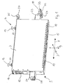
- Fig. 1 shows a printhead module 1 with a housing 3, at the top two suspension parts 4 are arranged.
- the hanger parts 4 enable the single-pass inkjet printer to have a hanging insertion of the printhead module 1 in order to achieve a later device-fixed printing position.
- Fig. 1 For orientation are in Fig. 1 the running direction 7 of a corresponding pressure medium, the transverse direction 8 perpendicular thereto and the vertical direction 9 are drawn. In the device-fixed printing position, the printing medium moves in the direction 7 under the printhead module 1 away.
- each printhead 10 comprises a number of nozzles held in a respective frame.
- the printhead module 1 further includes a number of ports 12 for supplying power, control signals, and ink. Inside the housing 3, the control electronics for driving the print heads 10 and an ink tank are housed.
- the housing 3 comprises a number of louvers 15 and an air inlet 16.
- About the air inlet 16 is introduced from the outside compressed air, which in particular on the louvers 15 again passes to the outside. This way will Keep dust or other contamination away from the printhead module 1.
- the hanging parts 4 are each formed as suspension pieces 19, which allow a pendulum suspension in a corresponding pan bearing.
- the suspension pieces 19 are each formed as conical pieces 20.
- the conical pieces 20 have a smaller angle of inclination than the pan of the corresponding bearing. Due to the offset in the transverse direction arrangement of the two conical pieces 20 takes place when attaching the printhead module 1 already its orientation parallel to the transverse direction 8.
- the two conical pieces 20 then allow in the corresponding pan bearing oscillation of the printhead module 1 by a polar angle. In other words, the printhead module 1 will align by gravity after hanging substantially in the vertical direction.
- the provided hanger parts 4 also allow the adjustment of an angle of inclination or polar angle in order to adjust the pressure bar with the printing heads 10 parallel to the path of the printing medium.
- the web of the printing medium may be formed, for example, as a curved arc, which allows a tighter management of the pressure medium.
- bearing pieces 23, 24 are mounted.
- each bearing pieces 23, 24 each have a height-adjustable ball studs 27, 28 is attached.
- each catching means 30 are mounted on the two bearing pieces 23, 24, wherein only the in Fig. 1 right catch 30 is located.
- the catching means 30 comprises a wedge shaft 32, which is open in the vertical direction 9 and has a groove groove 33 extending in the transverse direction 7 on its underside.
- a lifting-lowering device of a single-pass inkjet printer printhead module 1 reach the catch means 30 gradually in position with a corresponding Counterpart to the printer.
- This counterpart is in each case designed as a catch wedge oriented in the direction of travel 7.
- This catching wedge is first grasped by the groove groove 33 and slides into the vertical wedge shaft 32.
- Fang wedge of the single-pass inkjet printer and wedge shaft 32 each form a vertical slide guide in both bearing pieces 23, 24.
- the printhead module 1 Upon further lowering, the printhead module 1 aligns in the polar angle and in the transverse direction, since the catching means 30 gradually slide completely onto the device-fixed catching wedge. The catch means 30 thus cause a coarse positioning of the print head module 1 in its lowering relative to the final print position to be reached.
- one of the ball and socket bearings comprises a device-resistant pan with a countersink.
- the other of the two bearings comprises a prismatic recess extending in the transverse direction 8.
- the ball of the ball pin 27 forms, for example, with the conical countersink a three-dimensional fixed pivot point.
- the ball of the opposite ball pin 28 defines the position of the bearing piece 24 in the vertical direction 9 and 7 in the direction. In the transverse direction 8 a shift is possible due to the prismatic sink, whereby longitudinal extensions of the print head module 1 are collected.
- a stop piece 35 is provided on the upper side of the housing 3, which comprises a ball pin 37. This ball pin 37 comes laterally at a lowering of the printhead module 1 to a biased, spherical stop surface of the single-pass ink jet printer. This ensures that when digging the conical pieces 20 in the reached printing position of the inclination angle of the printhead module 1 is exactly defined.
- the printhead module 1 is limited by the provided three bearings in all degrees of freedom and thus accurately positioned.
- the stopper 35 is not mandatory.
- the hanger can be designed as a cutting edge bearing, which defines a pivot point exactly.
- the hanger in the printing position does not need to be excavated.
- the respective print heads 10 are aligned with respect to the balls of the ball studs 27, 28 in the direction 7 and in the transverse direction 8. At a later device fixed printing position, the print heads 10 are adjusted by height adjustment of the ball studs 27, 28 in the vertical direction 9.
- the position adjustment in the transverse direction 8 and in the running direction 7 of the push buttons 10 is effected by a longitudinally displaceable mounting in the housing 3.
- the position adjustment itself is made by light microscopy.
- the printhead module 1 shown is used with its bearings in a suitable tool that forms an identical storage of the later printing position.
Landscapes
- Ink Jet (AREA)
- Common Mechanisms (AREA)
- Particle Formation And Scattering Control In Inkjet Printers (AREA)
Claims (17)
- Module de tête d'impression (1) pour une imprimante à jet d'encre à une seule passe, comprenant un boîtier (3), une partie d'accrochage (4) fixée au boîtier (3) de manière à produire une suspension dans le sens de la force de gravité, et une pluralité de têtes d'impression (10) disposées sur le boîtier (3) le long d'une direction transversale (8) perpendiculaire à une direction d'avance (7), lesquelles sont ajustées en position par rapport à au moins une position de référence.
- Module de tête d'impression (1) selon la revendication 1,
dans lequel la partie d'accrochage (4) est réalisée sous forme de pièce de suspension (19) pouvant être suspendue de manière pendulaire à une pièce d'accrochage. - Module de tête d'impression (1) selon la revendication 2,
dans lequel la pièce de suspension (19) est réalisée sous forme de pièce conique (20). - Module de tête d'impression (1) selon l'une quelconque des revendications précédentes,
dans lequel il est prévu au moins deux parties d'accrochage (4) décalées dans la direction transversale (8). - Module de tête d'impression (1) selon l'une quelconque des revendications précédentes,
dans lequel des moyens de captage (30) sont disposés sur le boîtier (3) en vue d'un positionnement grossier par rapport à une position d'impression prévue. - Module de tête d'impression (1) selon la revendication 5,
dans lequel les moyens de captage (30) sont formés par une clavette de captage ou par une tige clavetée (32). - Module de tête d'impression (1) selon la revendication 6,
dans lequel la clavette de captage ou la tige clavetée (32) est réalisée de manière à former un guide de poussée essentiellement vertical avec une pièce conjuguée. - Module de tête d'impression (1) selon la revendication 6 ou 7,
dans lequel on prévoit en tant que moyen de captage (30) un coin de captage orienté parallèlement la direction d'avance (7) ou un renfoncement de rainure (33) orienté parallèlement à la direction d'avance (7). - Module de tête d'impression (1) selon l'une quelconque des revendications précédentes,
dans lequel au moins deux pièces de palier (23, 24) décalées dans la direction transversale (8) sont disposées sur le boîtier (3), lesquelles sont à chaque fois réalisées pour produire un positionnement avec auto-ajustage dans un palier ouvert. - Module de tête d'impression (1) selon la revendication 9,
dans lequel les pièces de palier (23, 24) sont réglables en hauteur. - Module de tête d'impression (1) selon la revendication 9 ou 10,
dans lequel l'une des pièces de palier (23, 24) est réalisée en vue d'un positionnement dans un palier fixe et l'autre des pièces de palier (23, 24) est réalisée en vue d'un positionnement dans un palier fou dans la direction transversale. - Module de tête d'impression (1) selon l'une quelconque des revendications 9 à 11,
dans lequel les pièces de palier (23, 24) sont à chaque fois réalisées sous forme de tourillons coniques (27, 28). - Module de tête d'impression (1) selon l'une quelconque des revendications précédentes, qui comprend une pièce de butée (35) pour buter contre une surface de butée.
- Module de tête d'impression (1) selon la revendication 13,
dans lequel la pièce de butée (35) comprend un tourillon conique (37) s'étendant dans la direction transversale. - Module de tête d'impression (1) selon l'une quelconque des revendications 9 à 14,
dans lequel les têtes d'impression (10) sont à chaque fois ajustées en position par rapport aux pièces de palier (23, 24). - Module de tête d'impression (1) selon l'une quelconque des revendications précédentes,
dans lequel une électronique de commande et/ou un réservoir d'encre sont montés dans le boîtier (3). - Module de tête d'impression (1) selon l'une quelconque des revendications précédentes,
dans lequel le boîtier (3) comprend une pluralité de fentes d'air (15), et dans lequel il est prévu une alimentation en air (16) dans l'espace interne du boîtier.
Priority Applications (1)
| Application Number | Priority Date | Filing Date | Title |
|---|---|---|---|
| PL10734031T PL2582526T3 (pl) | 2010-06-18 | 2010-06-18 | Moduł głowicy drukującej |
Applications Claiming Priority (1)
| Application Number | Priority Date | Filing Date | Title |
|---|---|---|---|
| PCT/EP2010/003681 WO2011157281A1 (fr) | 2010-06-18 | 2010-06-18 | Module de têtes d'impression |
Publications (2)
| Publication Number | Publication Date |
|---|---|
| EP2582526A1 EP2582526A1 (fr) | 2013-04-24 |
| EP2582526B1 true EP2582526B1 (fr) | 2014-11-12 |
Family
ID=43795157
Family Applications (1)
| Application Number | Title | Priority Date | Filing Date |
|---|---|---|---|
| EP10734031.7A Active EP2582526B1 (fr) | 2010-06-18 | 2010-06-18 | Module de tête à jet d'encre |
Country Status (10)
| Country | Link |
|---|---|
| US (1) | US8960858B2 (fr) |
| EP (1) | EP2582526B1 (fr) |
| CN (1) | CN102947101B (fr) |
| CA (1) | CA2802898C (fr) |
| DK (1) | DK2582526T3 (fr) |
| ES (1) | ES2525810T3 (fr) |
| PL (1) | PL2582526T3 (fr) |
| PT (1) | PT2582526E (fr) |
| RU (1) | RU2524896C1 (fr) |
| WO (1) | WO2011157281A1 (fr) |
Families Citing this family (6)
| Publication number | Priority date | Publication date | Assignee | Title |
|---|---|---|---|---|
| CN104066588B (zh) * | 2012-01-27 | 2016-02-24 | 惠普发展公司,有限责任合伙企业 | 打印头组件基准 |
| WO2016096026A1 (fr) | 2014-12-18 | 2016-06-23 | Padaluma Ink-Jet-Solutions Gmbh & Co. Kg | Module à têtes d'impression |
| CN109421370A (zh) * | 2017-08-21 | 2019-03-05 | 精工爱普生株式会社 | 液滴喷吐装置 |
| TWI615267B (zh) * | 2017-09-20 | 2018-02-21 | 東友科技股份有限公司 | 雙噴頭組件及其適用之三維列印裝置 |
| WO2020081597A1 (fr) | 2018-10-15 | 2020-04-23 | Aharon Alon S | Systèmes et procédés d'accès et de distribution par perforation magnétique |
| EP3733420B1 (fr) * | 2019-05-02 | 2023-03-29 | Artech GmbH design + production in plastic | Module de tête d'impression et système d'impression d'essai |
Family Cites Families (12)
| Publication number | Priority date | Publication date | Assignee | Title |
|---|---|---|---|---|
| JP2810701B2 (ja) * | 1989-05-31 | 1998-10-15 | キヤノン株式会社 | インクジェット記録ヘッドおよびインクジェット記録装置 |
| DE69109705T2 (de) * | 1990-02-13 | 1996-01-04 | Canon Kk | Aufzeichnungsgerät mit Tintenstrahlaufzeichnungskopf. |
| KR100438655B1 (ko) * | 2000-09-25 | 2004-07-07 | 주식회사 창대바이오 | 생체를 이용한 한방차 자동 판매 장치 및 그 방법 |
| JP3823994B2 (ja) * | 2004-01-22 | 2006-09-20 | セイコーエプソン株式会社 | ワイピング装置、これを備えた描画装置、電気光学装置の製造方法 |
| JP2005276148A (ja) * | 2004-03-25 | 2005-10-06 | Next Force Corp | サプリメント問診システムの提供及びサプリメント供給装置 |
| CN1984780B (zh) | 2004-04-30 | 2010-09-22 | 富士胶片戴麦提克斯公司 | 液滴喷射装置对准 |
| WO2006128859A1 (fr) * | 2005-05-30 | 2006-12-07 | Agfa Graphics Nv | Ensemble de montage de tete d’impression et procede de montage d’une tete d’impression sur un chassis de chariot |
| CN101184627B (zh) | 2005-05-30 | 2010-08-18 | 爱克发印艺公司 | 打印头安装组件及将打印头安装到支座框架上的方法 |
| TW200815198A (en) * | 2006-09-22 | 2008-04-01 | Microjet Technology Co Ltd | Printing apparatus |
| JPWO2008152903A1 (ja) | 2007-06-11 | 2010-08-26 | コニカミノルタホールディングス株式会社 | インクジェットヘッドユニットおよびインクジェット記録装置 |
| US8888247B2 (en) * | 2011-06-03 | 2014-11-18 | Ricoh Company, Ltd. | Image forming apparatus including recording head for ejecting liquid droplets |
| US9079439B2 (en) * | 2012-04-13 | 2015-07-14 | Hewlett-Packard Development Company, L.P. | Rotatable printhead assembly |
-
2010
- 2010-06-18 US US13/701,637 patent/US8960858B2/en active Active
- 2010-06-18 RU RU2012149672/12A patent/RU2524896C1/ru active
- 2010-06-18 CA CA2802898A patent/CA2802898C/fr active Active
- 2010-06-18 PT PT107340317T patent/PT2582526E/pt unknown
- 2010-06-18 EP EP10734031.7A patent/EP2582526B1/fr active Active
- 2010-06-18 ES ES10734031.7T patent/ES2525810T3/es active Active
- 2010-06-18 CN CN201080067409.5A patent/CN102947101B/zh active Active
- 2010-06-18 DK DK10734031.7T patent/DK2582526T3/en active
- 2010-06-18 PL PL10734031T patent/PL2582526T3/pl unknown
- 2010-06-18 WO PCT/EP2010/003681 patent/WO2011157281A1/fr active Application Filing
Also Published As
| Publication number | Publication date |
|---|---|
| WO2011157281A1 (fr) | 2011-12-22 |
| PT2582526E (pt) | 2015-01-14 |
| DK2582526T3 (en) | 2014-12-08 |
| US8960858B2 (en) | 2015-02-24 |
| RU2012149672A (ru) | 2014-07-27 |
| CN102947101A (zh) | 2013-02-27 |
| RU2524896C1 (ru) | 2014-08-10 |
| CA2802898A1 (fr) | 2011-12-22 |
| US20130100209A1 (en) | 2013-04-25 |
| ES2525810T3 (es) | 2014-12-30 |
| EP2582526A1 (fr) | 2013-04-24 |
| CN102947101B (zh) | 2016-03-16 |
| CA2802898C (fr) | 2016-08-16 |
| PL2582526T3 (pl) | 2015-04-30 |
Similar Documents
| Publication | Publication Date | Title |
|---|---|---|
| EP2582527B1 (fr) | Imprimant à passe unique | |
| EP2582526B1 (fr) | Module de tête à jet d'encre | |
| EP3233501B1 (fr) | Module de tête d'impression | |
| EP3253581B1 (fr) | Imprimante à jet d'encre monopasse | |
| EP2872335B1 (fr) | Dispositif de réglage pour tête d'impression | |
| EP2832546B1 (fr) | Imprimante dotée d'une commande de tête d'impression | |
| DE102010060405B4 (de) | Vorrichtung zur Positionierung mindestens eines Druckriegels in Druckposition bei einem Tintendruckgerät | |
| DE102013207481A1 (de) | Luftlager-Substrat-Medientransport | |
| DE2731704A1 (de) | Praezisionstisch fuer die ausfuehrung einer zweidimensionalen bewegung | |
| DE60304540T2 (de) | Führungsanordnung für Tintenstrahldrucker | |
| EP2065206A1 (fr) | Dispositif d'enrichissement de pièces usinées | |
| EP3411240A1 (fr) | Procédé et dispositif d'impression | |
| DE102010060406B4 (de) | Vorrichtung und Verfahren zur Positionierung mindestens eines Druckriegels im Gehäuse einer Druckeinheit bei einem Tintendruckgerät | |
| DE602005003003T2 (de) | Druckkopfwagen | |
| DE60021073T2 (de) | Tragprofil für Transferwagen | |
| DE102012103712B4 (de) | Vorrichtung und Verfahren zum seriellen Bedrucken von Druckmedien | |
| DE102013002254A1 (de) | Modularer Düsenstock mit Überwachungsmodul | |
| DE2618001C3 (de) | Baueinheit zur Führung eines Druckkopfes parallel zum Druckwiderlager in Buchungs- und Rechenmaschinen | |
| DE20012946U1 (de) | Tintenstrahldrucker, insbesondere zur Beschriftung von Versandstücken | |
| DE60206722T2 (de) | Druckwagenlagerung für einen Druckkopf | |
| DE60206589T2 (de) | Ausrichtvorrichtung und Ausrichtverfahren für Tintenstrahldrucker | |
| DE102005056542B4 (de) | Druckmaschine mit mindestens einem Druckkopf und einer Druckkopf-Positioniervorrichtung | |
| WO2021047994A1 (fr) | Ensemble d'impression | |
| DE102016215113A1 (de) | Druckaggregat mit Abdeckeinrichtung und/oder und Reinigungsvorrichtung | |
| WO2024064986A1 (fr) | Agencement de têtes d'impression et procédé de réglage de têtes d'impression |
Legal Events
| Date | Code | Title | Description |
|---|---|---|---|
| PUAI | Public reference made under article 153(3) epc to a published international application that has entered the european phase |
Free format text: ORIGINAL CODE: 0009012 |
|
| 17P | Request for examination filed |
Effective date: 20121203 |
|
| AK | Designated contracting states |
Kind code of ref document: A1 Designated state(s): AL AT BE BG CH CY CZ DE DK EE ES FI FR GB GR HR HU IE IS IT LI LT LU LV MC MK MT NL NO PL PT RO SE SI SK SM TR |
|
| DAX | Request for extension of the european patent (deleted) | ||
| REG | Reference to a national code |
Ref country code: DE Ref legal event code: R079 Ref document number: 502010008247 Country of ref document: DE Free format text: PREVIOUS MAIN CLASS: B41J0025340000 Ipc: B41J0002515000 |
|
| GRAP | Despatch of communication of intention to grant a patent |
Free format text: ORIGINAL CODE: EPIDOSNIGR1 |
|
| RIC1 | Information provided on ipc code assigned before grant |
Ipc: B41J 2/515 20060101AFI20140716BHEP Ipc: B41J 25/34 20060101ALI20140716BHEP |
|
| INTG | Intention to grant announced |
Effective date: 20140729 |
|
| GRAS | Grant fee paid |
Free format text: ORIGINAL CODE: EPIDOSNIGR3 |
|
| GRAA | (expected) grant |
Free format text: ORIGINAL CODE: 0009210 |
|
| AK | Designated contracting states |
Kind code of ref document: B1 Designated state(s): AL AT BE BG CH CY CZ DE DK EE ES FI FR GB GR HR HU IE IS IT LI LT LU LV MC MK MT NL NO PL PT RO SE SI SK SM TR |
|
| REG | Reference to a national code |
Ref country code: GB Ref legal event code: FG4D Free format text: NOT ENGLISH |
|
| REG | Reference to a national code |
Ref country code: CH Ref legal event code: EP |
|
| REG | Reference to a national code |
Ref country code: AT Ref legal event code: REF Ref document number: 695490 Country of ref document: AT Kind code of ref document: T Effective date: 20141115 |
|
| REG | Reference to a national code |
Ref country code: IE Ref legal event code: FG4D Free format text: LANGUAGE OF EP DOCUMENT: GERMAN |
|
| REG | Reference to a national code |
Ref country code: DK Ref legal event code: T3 Effective date: 20141204 |
|
| REG | Reference to a national code |
Ref country code: DE Ref legal event code: R096 Ref document number: 502010008247 Country of ref document: DE Effective date: 20141224 |
|
| REG | Reference to a national code |
Ref country code: ES Ref legal event code: FG2A Ref document number: 2525810 Country of ref document: ES Kind code of ref document: T3 Effective date: 20141230 |
|
| REG | Reference to a national code |
Ref country code: CH Ref legal event code: NV Representative=s name: E. BLUM AND CO. AG PATENT- UND MARKENANWAELTE , CH Ref country code: NL Ref legal event code: T3 |
|
| REG | Reference to a national code |
Ref country code: PT Ref legal event code: SC4A Free format text: AVAILABILITY OF NATIONAL TRANSLATION Effective date: 20150102 |
|
| REG | Reference to a national code |
Ref country code: SE Ref legal event code: TRGR |
|
| PG25 | Lapsed in a contracting state [announced via postgrant information from national office to epo] |
Ref country code: IS Free format text: LAPSE BECAUSE OF FAILURE TO SUBMIT A TRANSLATION OF THE DESCRIPTION OR TO PAY THE FEE WITHIN THE PRESCRIBED TIME-LIMIT Effective date: 20150312 Ref country code: FI Free format text: LAPSE BECAUSE OF FAILURE TO SUBMIT A TRANSLATION OF THE DESCRIPTION OR TO PAY THE FEE WITHIN THE PRESCRIBED TIME-LIMIT Effective date: 20141112 Ref country code: NO Free format text: LAPSE BECAUSE OF FAILURE TO SUBMIT A TRANSLATION OF THE DESCRIPTION OR TO PAY THE FEE WITHIN THE PRESCRIBED TIME-LIMIT Effective date: 20150212 Ref country code: LT Free format text: LAPSE BECAUSE OF FAILURE TO SUBMIT A TRANSLATION OF THE DESCRIPTION OR TO PAY THE FEE WITHIN THE PRESCRIBED TIME-LIMIT Effective date: 20141112 |
|
| REG | Reference to a national code |
Ref country code: PL Ref legal event code: T3 |
|
| PG25 | Lapsed in a contracting state [announced via postgrant information from national office to epo] |
Ref country code: LV Free format text: LAPSE BECAUSE OF FAILURE TO SUBMIT A TRANSLATION OF THE DESCRIPTION OR TO PAY THE FEE WITHIN THE PRESCRIBED TIME-LIMIT Effective date: 20141112 Ref country code: HR Free format text: LAPSE BECAUSE OF FAILURE TO SUBMIT A TRANSLATION OF THE DESCRIPTION OR TO PAY THE FEE WITHIN THE PRESCRIBED TIME-LIMIT Effective date: 20141112 Ref country code: CY Free format text: LAPSE BECAUSE OF FAILURE TO SUBMIT A TRANSLATION OF THE DESCRIPTION OR TO PAY THE FEE WITHIN THE PRESCRIBED TIME-LIMIT Effective date: 20141112 Ref country code: GR Free format text: LAPSE BECAUSE OF FAILURE TO SUBMIT A TRANSLATION OF THE DESCRIPTION OR TO PAY THE FEE WITHIN THE PRESCRIBED TIME-LIMIT Effective date: 20150213 |
|
| PG25 | Lapsed in a contracting state [announced via postgrant information from national office to epo] |
Ref country code: RO Free format text: LAPSE BECAUSE OF FAILURE TO SUBMIT A TRANSLATION OF THE DESCRIPTION OR TO PAY THE FEE WITHIN THE PRESCRIBED TIME-LIMIT Effective date: 20141112 Ref country code: SK Free format text: LAPSE BECAUSE OF FAILURE TO SUBMIT A TRANSLATION OF THE DESCRIPTION OR TO PAY THE FEE WITHIN THE PRESCRIBED TIME-LIMIT Effective date: 20141112 Ref country code: EE Free format text: LAPSE BECAUSE OF FAILURE TO SUBMIT A TRANSLATION OF THE DESCRIPTION OR TO PAY THE FEE WITHIN THE PRESCRIBED TIME-LIMIT Effective date: 20141112 |
|
| REG | Reference to a national code |
Ref country code: DE Ref legal event code: R097 Ref document number: 502010008247 Country of ref document: DE |
|
| PLBE | No opposition filed within time limit |
Free format text: ORIGINAL CODE: 0009261 |
|
| STAA | Information on the status of an ep patent application or granted ep patent |
Free format text: STATUS: NO OPPOSITION FILED WITHIN TIME LIMIT |
|
| 26N | No opposition filed |
Effective date: 20150813 |
|
| PG25 | Lapsed in a contracting state [announced via postgrant information from national office to epo] |
Ref country code: MC Free format text: LAPSE BECAUSE OF FAILURE TO SUBMIT A TRANSLATION OF THE DESCRIPTION OR TO PAY THE FEE WITHIN THE PRESCRIBED TIME-LIMIT Effective date: 20141112 |
|
| PG25 | Lapsed in a contracting state [announced via postgrant information from national office to epo] |
Ref country code: SI Free format text: LAPSE BECAUSE OF FAILURE TO SUBMIT A TRANSLATION OF THE DESCRIPTION OR TO PAY THE FEE WITHIN THE PRESCRIBED TIME-LIMIT Effective date: 20141112 |
|
| REG | Reference to a national code |
Ref country code: IE Ref legal event code: MM4A |
|
| PG25 | Lapsed in a contracting state [announced via postgrant information from national office to epo] |
Ref country code: IE Free format text: LAPSE BECAUSE OF NON-PAYMENT OF DUE FEES Effective date: 20150618 |
|
| REG | Reference to a national code |
Ref country code: FR Ref legal event code: PLFP Year of fee payment: 7 |
|
| PG25 | Lapsed in a contracting state [announced via postgrant information from national office to epo] |
Ref country code: MT Free format text: LAPSE BECAUSE OF FAILURE TO SUBMIT A TRANSLATION OF THE DESCRIPTION OR TO PAY THE FEE WITHIN THE PRESCRIBED TIME-LIMIT Effective date: 20141112 |
|
| PG25 | Lapsed in a contracting state [announced via postgrant information from national office to epo] |
Ref country code: HU Free format text: LAPSE BECAUSE OF FAILURE TO SUBMIT A TRANSLATION OF THE DESCRIPTION OR TO PAY THE FEE WITHIN THE PRESCRIBED TIME-LIMIT; INVALID AB INITIO Effective date: 20100618 Ref country code: SM Free format text: LAPSE BECAUSE OF FAILURE TO SUBMIT A TRANSLATION OF THE DESCRIPTION OR TO PAY THE FEE WITHIN THE PRESCRIBED TIME-LIMIT Effective date: 20141112 Ref country code: BG Free format text: LAPSE BECAUSE OF FAILURE TO SUBMIT A TRANSLATION OF THE DESCRIPTION OR TO PAY THE FEE WITHIN THE PRESCRIBED TIME-LIMIT Effective date: 20141112 |
|
| REG | Reference to a national code |
Ref country code: FR Ref legal event code: PLFP Year of fee payment: 8 |
|
| REG | Reference to a national code |
Ref country code: FR Ref legal event code: PLFP Year of fee payment: 9 |
|
| PG25 | Lapsed in a contracting state [announced via postgrant information from national office to epo] |
Ref country code: MK Free format text: LAPSE BECAUSE OF FAILURE TO SUBMIT A TRANSLATION OF THE DESCRIPTION OR TO PAY THE FEE WITHIN THE PRESCRIBED TIME-LIMIT Effective date: 20141112 |
|
| PG25 | Lapsed in a contracting state [announced via postgrant information from national office to epo] |
Ref country code: AL Free format text: LAPSE BECAUSE OF FAILURE TO SUBMIT A TRANSLATION OF THE DESCRIPTION OR TO PAY THE FEE WITHIN THE PRESCRIBED TIME-LIMIT Effective date: 20141112 |
|
| PGFP | Annual fee paid to national office [announced via postgrant information from national office to epo] |
Ref country code: PT Payment date: 20190612 Year of fee payment: 10 Ref country code: CZ Payment date: 20190611 Year of fee payment: 10 Ref country code: PL Payment date: 20190604 Year of fee payment: 10 |
|
| PGFP | Annual fee paid to national office [announced via postgrant information from national office to epo] |
Ref country code: SI Payment date: 20190417 Year of fee payment: 10 |
|
| PG25 | Lapsed in a contracting state [announced via postgrant information from national office to epo] |
Ref country code: CZ Free format text: LAPSE BECAUSE OF NON-PAYMENT OF DUE FEES Effective date: 20200618 |
|
| PG25 | Lapsed in a contracting state [announced via postgrant information from national office to epo] |
Ref country code: PT Free format text: LAPSE BECAUSE OF NON-PAYMENT OF DUE FEES Effective date: 20210121 |
|
| PG25 | Lapsed in a contracting state [announced via postgrant information from national office to epo] |
Ref country code: TR Free format text: LAPSE BECAUSE OF NON-PAYMENT OF DUE FEES Effective date: 20200618 |
|
| PG25 | Lapsed in a contracting state [announced via postgrant information from national office to epo] |
Ref country code: PL Free format text: LAPSE BECAUSE OF NON-PAYMENT OF DUE FEES Effective date: 20200618 |
|
| PGFP | Annual fee paid to national office [announced via postgrant information from national office to epo] |
Ref country code: NL Payment date: 20230620 Year of fee payment: 14 Ref country code: FR Payment date: 20230621 Year of fee payment: 14 Ref country code: DK Payment date: 20230621 Year of fee payment: 14 Ref country code: DE Payment date: 20230628 Year of fee payment: 14 |
|
| PGFP | Annual fee paid to national office [announced via postgrant information from national office to epo] |
Ref country code: SE Payment date: 20230622 Year of fee payment: 14 Ref country code: LU Payment date: 20230619 Year of fee payment: 14 Ref country code: AT Payment date: 20230616 Year of fee payment: 14 |
|
| PGFP | Annual fee paid to national office [announced via postgrant information from national office to epo] |
Ref country code: BE Payment date: 20230619 Year of fee payment: 14 |
|
| PGFP | Annual fee paid to national office [announced via postgrant information from national office to epo] |
Ref country code: IT Payment date: 20230630 Year of fee payment: 14 Ref country code: GB Payment date: 20230622 Year of fee payment: 14 Ref country code: ES Payment date: 20230719 Year of fee payment: 14 Ref country code: CH Payment date: 20230702 Year of fee payment: 14 |